EP1663819B1 - Modular link conveyor chain with rotatable article engaging assemblies - Google Patents
Modular link conveyor chain with rotatable article engaging assemblies Download PDFInfo
- Publication number
- EP1663819B1 EP1663819B1 EP04784143A EP04784143A EP1663819B1 EP 1663819 B1 EP1663819 B1 EP 1663819B1 EP 04784143 A EP04784143 A EP 04784143A EP 04784143 A EP04784143 A EP 04784143A EP 1663819 B1 EP1663819 B1 EP 1663819B1
- Authority
- EP
- European Patent Office
- Prior art keywords
- chain
- cap
- links
- connector
- article
- Prior art date
- Legal status (The legal status is an assumption and is not a legal conclusion. Google has not performed a legal analysis and makes no representation as to the accuracy of the status listed.)
- Not-in-force
Links
Images

Classifications
-
- B—PERFORMING OPERATIONS; TRANSPORTING
- B65—CONVEYING; PACKING; STORING; HANDLING THIN OR FILAMENTARY MATERIAL
- B65G—TRANSPORT OR STORAGE DEVICES, e.g. CONVEYORS FOR LOADING OR TIPPING, SHOP CONVEYOR SYSTEMS OR PNEUMATIC TUBE CONVEYORS
- B65G17/00—Conveyors having an endless traction element, e.g. a chain, transmitting movement to a continuous or substantially-continuous load-carrying surface or to a series of individual load-carriers; Endless-chain conveyors in which the chains form the load-carrying surface
- B65G17/24—Conveyors having an endless traction element, e.g. a chain, transmitting movement to a continuous or substantially-continuous load-carrying surface or to a series of individual load-carriers; Endless-chain conveyors in which the chains form the load-carrying surface comprising a series of rollers which are moved, e.g. over a supporting surface, by the traction element to effect conveyance of loads or load-carriers
-
- B—PERFORMING OPERATIONS; TRANSPORTING
- B65—CONVEYING; PACKING; STORING; HANDLING THIN OR FILAMENTARY MATERIAL
- B65G—TRANSPORT OR STORAGE DEVICES, e.g. CONVEYORS FOR LOADING OR TIPPING, SHOP CONVEYOR SYSTEMS OR PNEUMATIC TUBE CONVEYORS
- B65G17/00—Conveyors having an endless traction element, e.g. a chain, transmitting movement to a continuous or substantially-continuous load-carrying surface or to a series of individual load-carriers; Endless-chain conveyors in which the chains form the load-carrying surface
- B65G17/06—Conveyors having an endless traction element, e.g. a chain, transmitting movement to a continuous or substantially-continuous load-carrying surface or to a series of individual load-carriers; Endless-chain conveyors in which the chains form the load-carrying surface having a load-carrying surface formed by a series of interconnected, e.g. longitudinal, links, plates, or platforms
- B65G17/063—Conveyors having an endless traction element, e.g. a chain, transmitting movement to a continuous or substantially-continuous load-carrying surface or to a series of individual load-carriers; Endless-chain conveyors in which the chains form the load-carrying surface having a load-carrying surface formed by a series of interconnected, e.g. longitudinal, links, plates, or platforms the load carrying surface being formed by profiles, rods, bars, rollers or the like attached to more than one traction element
-
- B—PERFORMING OPERATIONS; TRANSPORTING
- B65—CONVEYING; PACKING; STORING; HANDLING THIN OR FILAMENTARY MATERIAL
- B65G—TRANSPORT OR STORAGE DEVICES, e.g. CONVEYORS FOR LOADING OR TIPPING, SHOP CONVEYOR SYSTEMS OR PNEUMATIC TUBE CONVEYORS
- B65G17/00—Conveyors having an endless traction element, e.g. a chain, transmitting movement to a continuous or substantially-continuous load-carrying surface or to a series of individual load-carriers; Endless-chain conveyors in which the chains form the load-carrying surface
- B65G17/30—Details; Auxiliary devices
- B65G17/32—Individual load-carriers
-
- B—PERFORMING OPERATIONS; TRANSPORTING
- B65—CONVEYING; PACKING; STORING; HANDLING THIN OR FILAMENTARY MATERIAL
- B65G—TRANSPORT OR STORAGE DEVICES, e.g. CONVEYORS FOR LOADING OR TIPPING, SHOP CONVEYOR SYSTEMS OR PNEUMATIC TUBE CONVEYORS
- B65G39/00—Rollers, e.g. drive rollers, or arrangements thereof incorporated in roller-ways or other types of mechanical conveyors
- B65G39/02—Adaptations of individual rollers and supports therefor
- B65G39/025—Adaptations of individual rollers and supports therefor having spherical roller elements
Definitions
- This invention relates to a conveyor chain especially adapted for use in situations where moving articles in both a conveying direction and a direction different from the conveying direction may be desirable.
- modular link conveyors in industry enjoys increasing popularity. Particularly for conveying food articles or consumer products, especially in packages or in semi-packaged form, the modular link conveyor represents the overwhelming choice of those in the industry looking for a long-lasting, low cost conveying solution. In the recent past, significant advances in the development of such have been made so as to provide more efficient handling of an even larger variety of food articles, packages and containers, as well as other types of articles and products.
- the spherical balls are recessed such that only a small amount of the surface is available for engaging the articles, which would otherwise tend to drag on the stationary link forming the vast majority of the conveying surface.
- the spherical balls may pop-out of the recesses under moderate shearing forces unless a separate cover is used. Losing even a single ball not only renders the links ineffective for use as intended, but also adds to the maintenance expense. The solution of providing a partial cover also complicates the overall assembly, adds to the manufacturing cost, and creates a protruding lip on which the articles may become caught during conveyance.
- an improved modular link chain for use in conveying articles or objects capable of achieving low backline pressure, such as in an accumulation mode, and also allowing for the easy, efficient, and smooth diversion of articles in a direction besides the conveying direction.
- the chain comprises a plurality of modular links forming a conveying surface, at least one article engaging assembly also forming part of the conveying surface and including a body supporting at least one rotatably mounted cap, and a transverse connector connecting the modular links and rotatably supporting the body.
- the article engaging assembly may rotate in the conveying direction to provide low backline pressure for the articles and may facilitate article movement in the different direction through engagement with the rotatably mounted cap.
- the article engaging assembly includes first and second rotatably mounted caps, each having a generally spherical outer surface.
- the body includes first and second generally opposed supports for receiving and supporting the first and second caps.
- Each support extends in a direction generally transverse to a longitudinal axis of the connector, and each cap includes a recess having a first portion adapted for receiving and holding an oversized portion of the corresponding support to capture the cap thereon.
- the recess includes a second portion adapted for receiving a generally circular seating protrusion forming part of the support, whereby the seating protrusion may provide a bearing surface for the cap.
- the seating protrusion may also include an outer surface having one or more indentations adapted for receiving a lubricant.
- the cap may include at least one relief area adapted for receiving a lubricant.
- the body includes a transverse channel for receiving the connector with sufficient clearance to permit free rotation, including when backline pressure is present.
- a plurality of article engaging assemblies may be rotatably supported by the transverse connector.
- each connector may rotatably support a plurality of article engaging assemblies.
- the first and second rows are spaced in the conveying direction, and spacers are supported by the connector associated with the first row of links such that the corresponding article engaging assemblies are laterally offset from the article engaging assemblies associated with the second row of links.
- the spacers may comprise rollers that project above a top edge of the modular links to prevent articles from catching on the top edge, including when backline pressure is present
- Each link may include an apex having a slot for receiving the transverse connector passing through an adjacent link.
- the slot permits side-flexing action to allow the chain to negotiate curves or bends, as well as longitudinal expansion and compression in the conveying direction.
- the chain may also be used as part of an overall conveyor system including a drive unit for driving the chain in an endless path along a support structure.
- the step of driving the chain in an endless path may also form part of a method of conveying.
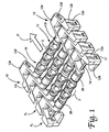
- FIG. 1 depicts an overall arrangement of a conveyor chain 10 constructed in accordance with one embodiment of the present invention and defining a conveying surface 11 for engaging and supporting articles.
- the chain 10 comprises or includes modular links in the form of side links 12 arranged in spaced apart rows, which thus partially create the conveying surface 11.
- the rows are interconnected by transverse connectors 14 carrying one or more article engaging assemblies 16.
- the construction and function of these assemblies 16 is outlined further in the following description.
- each may be identical, or optionally may include an outer depending arm 12a and an inwardly projecting transverse tab 12b (thus creating different right handed or left handed side links, depending on the particular positioning).
- the depending arm 12a and transverse tab 12b are designed to receive a conventional support structure, which may include a guide rail G (see Figures 4 and 5b ).
- Each guide rail G may comprise a wear strip W formed of a tribologically enhanced material to provide reduced friction contact with the links 12.
- the support structure formed with guide rails of this type is typically used to guide the chain 10 as it is driven in an endless path (such as by a pair of spaced sprockets adapted for engaging the links along a transition from a forward to a return run, or alternatively at an intermediate position).
- Links 12 of this sort are typically formed of Nylon 6-6, Acetal, or other inexpensive, lightweight, and durable materials using well-known forming techniques (including possibly co-molding of different materials).
- pairs of side links 12 form rows and are spaced in the direction in which the chain 10 is typically driven (referred to as the longitudinal direction or the conveying direction (note action arrow D), since it corresponds to the main direction in which articles are conveyed by the chain 10 during normal operation, as opposed to the transverse or lateral direction P; see Figure 5b ).
- the transverse connector 14 takes the form of a stainless steel rod passing through aligned holes (see Figure 2a ) formed in foot portions 12c of each generally V-shaped link (and, as described further below, through the article engaging assembly 16 itself).
- the links 12 of a second, adjacent (trailing) row R 2 are interdigitated with the first row R 1 , with the connector 14 passing through a slot 12d elongated in the conveying direction D and formed in the apex 12e of each link.
- this specific structural arrangement (which is considered entirely optional) allows for the chain 10 to side-flex to negotiate curves or bends, as well as to compress or expand in the longitudinal direction. If such enhanced functionality is not necessary for a particular application, the slots could, simply be replaced with plain holes for receiving the connector 14, which would this result in a non-side flexing, non-longitudinally compressible chain.
- the connector 14 is retained in place by a locking element or tab 17 removably inserted in a receiver 12f or slot formed in each side link 12.
- the tab 17 may include a recess 17a for engaging a necked or recessed portion 14a of the connector 14. This pattern of assembly may be repeated as necessary to form a chain 10 having a particular length in the conveying direction.
- a full description of this type of chain, or conveyor "belt" as it is sometimes called in the vernacular, is found in the commonly assigned '693 and '757 patents.
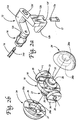
- each assembly 16 includes a body 18 or chassis with an internal channel 20 or bore adapted for receiving the connector 14 extending between and interconnecting the links 12.
- the channel 20 is cylindrical, having a longitudinal axis L extending generally transverse to the conveying direction D and a diameter just slightly larger than the diameter of corresponding connector 14 to create sufficient clearance for rotation. Consequently, each , body 18 is free to rotate independently about the connector 14 and in a direction generally corresponding to the conveying direction (see Figure 4 and note action arrows K) about an axis transverse thereto.
- the body 18 further includes at least one and preferably a pair of opposed, generally outwardly projecting supports.
- the supports may be in the form of generally cylindrical mounting posts or shafts 22 adapted for receiving and rotatably supporting a corresponding cap 24 forming a portion of the article conveying surface.
- Each shaft 22 may include an oversized portion 26 creating a circumferentially disposed, radially projecting lip for engaging a matching first portion 28a of a cavity or recess 28 in the cap 24 created by a neck 27.
- the recess 28 forms part of a internal hub for the cap 24 for receiving the support or shaft 22.
- the oversized portion 26 is preferably at the head end of the shaft 22 and is sized to engage the corresponding first internal portion 28a of the recess 28 and remain temporarily held or captured therein upon insertion by way of snap-fit engagement. This allows for the easy installation of the cap 24 on the shaft 22 using manual (finger) pressure and removal in a similar fashion (possibly with the additional use of a simple tool, such as a flathead screwdriver, to overcome any resistance created).
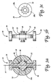
- the shaft 22 may also be stepped and include a seating protrusion 30 corresponding to a second portion 28b of the recess 28.
- this seating protrusion 30 may form a bearing surface 30a for engaging the corresponding or matching surface 24a of the cap 24 adjacent the hub. Whether engagement is present depends on the relative spacing created between these parts (which may vary due to tolerances, which are preferably tight to avoid creating a large space at this interface where debris may enter and accumulate).
- the portion of the body 18 adjacent the periphery of the cap 24 in the mounted position is also preferably circular in profile, with a diameter matching the corresponding dimension of the cap (see Figure 1 ).
- the width of the portion of the body 18 i.e., the portion sandwiched between the caps is preferably such that a complete sphere is defined.
- this portion of the body 18 may also help to engage and support the articles being conveyed.
- a sidewall of the seating protrusion 30 may also include an outer surface having one or more indentations 32 or dimples.
- these indentations 32 may be circumferentially spaced and are designed to receive a lubricant (e.g., silicone oil) applied externally during the assembly procedure.
- a lubricant e.g., silicone oil
- the lubricant pockets or “wells" thus created help to ensure that the desirable smooth and uninterrupted rotation of the cap 24 is maintained at all times.
- the indentations 32 also help to retain the lubricant in the interior of the cap 24 where it is needed most, and tend to reduce the frequency with which maintenance is required.
- the surface of the cap 24 adjacent to the hub may be provided with circumferentially spaced, radially extending relief areas (note phantom depiction of cutouts 34 in Figure 3c ) for performing a similar lubricant retention function.
- Each cap 24 in the illustrated embodiment is unitary with a generally spherical outer surface.
- the caps 24 may each be generally hemispherical in shape (see, e.g., Figure 3a ) but preferably are only partially spherical (i.e., a spherical "cap,” which is the region of a sphere lying above or below a given plane; sometimes also called a spherical "segment”).
- the generally spherical, hemispherical, or partially spherical cap 24 unlike a roller or recessed spherical ball includes a large, fully exposed outer surface area for engaging the articles positioned on the chain 10.
- the use of a spherical outer surface also tends to minimize the amount of "dead space" on the surface where an article could possibly stall.
- stalling is unlikely in view of the ability of the assemblies 16 to rotate independently of one another and thus assume a position where engagement with the cap 24 is established (see Figure 5b ).
- the caps 24 are preferably sized to project well above this edge, regardless of the orientation of the body 18 (also see Figure 5b ).
- the opposed sides of the body 18 are provided with shoulders 36, which although considered optional are preferred to allow adjacent bodies 18 to engage one another in an abutting relationship and prevent interference among the caps 24 of adjacent assemblies 16.
- the shoulders 36 may also engage a corresponding face of the side link 12 adjacent the foot portion 12c, as well as any other structures present on the connector 14 (such as a spacer, the function of which is outlined further in the following description).
- the shoulders 36 may be rounded or circular in profile, and are preferably of a reduced height relative to the apex or center of the cap 24 (which in the spherical cap coincide) and most preferably match with the top edge of the links 12.
- the resulting assembly (which has a generally I-shaped profile; see Figure 3b ) is considered symmetrical about a plane drawn through the body 18 and generally aligned with the transverse direction (see axis A in Figure 3a ).
- alternating connectors 14 may be provided with one or more spacers. These spacers, which are shown in the form of rollers 38, advantageously serve to stagger or laterally offset the assemblies 16 on alternating connectors 14 such that the chance of product stalling is significantly reduced or eliminated.
- rollers 38 it is preferable to use oversized ones such that the outer surface projects well above the top edge of the corresponding links 12 (e.g., at least 10% of the diameter of the roller; see Figure 4 ). This helps to prevent the articles from catching on the links 12, especially during movement in a direction different from the conveying direction (e.g., the transverse direction P).
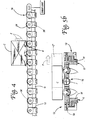
- a conveyor system including the chain 10 constructed as described above and mounted on a guide rail G is explained.
- the chain 10 is moved along an endless path as described above to convey an article, such as a carton C, from one location to another.
- the driving of the chain 10 may be accomplished by sprocket(s) associated with or forming part of a drive unit.
- the weight of the article typically keeps the assemblies 16 from rotating during conventional operation, which means that the article, or carton C in this instance, travels at the same linear speed as the chain 10 (e.g.,0,3 m/s (1 ft/s)).
- the chain 10 with the assemblies 16 mounted for independent rotation on the connectors 14 allows for the desired operation to occur with low backline pressure and/or without damaging a single article being held stationary.
- the assemblies 16 are free to counter-rotate (note action arrows K in Figure 4 , which presumes the chain 10 is being driven forward in the conveying direction D). This helps to prevent the articles, such as cartons C, from becoming damaged by the chain 10 or from damaging (crushing) one another as a result of excessive backline pressure (note full line carton C and abutting carton C' with counter-rotation of assemblies 16 noted).
- each body 18 to rotate independently also helps to ensure that a cap 24 (with its large exposed outer surface) is always in a ready position for engaging the article on the conveying surface 11. Even if this is not the case and momentary catching or engagement with a dead spot occurs, the body 18 (which is typically moving in the conveying direction D during the diversion of the article) immediately tends to rotate such that the desired engagement with the rotatable cap 24 may be established.
- this technique can also be used to align articles on the chain 10 in rows, instead of diverting them onto a separate structure.
- links could also be positioned between selected assemblies 16, especially when several are present on a single connector (e.g., ten assemblies with a link between numbers five and six).
- corresponding support structure(s) such as a guide or support rail, not shown
- a row of assemblies could be followed by a row of links, or several rows of assemblies could be followed by one or more rows of links.
- each cap 24 with a channel (not shown) that extends completely through the center or apex of the spherical outer surface.
- a recessed seating ring may be provided in the outer surface for engaging the lip formed by the oversized portion 26 of the shaft 22 to capture the cap 24 thereon.
Abstract
Description
- This invention relates to a conveyor chain especially adapted for use in situations where moving articles in both a conveying direction and a direction different from the conveying direction may be desirable.
- The use of modular link conveyors in industry enjoys increasing popularity. Particularly for conveying food articles or consumer products, especially in packages or in semi-packaged form, the modular link conveyor represents the overwhelming choice of those in the industry looking for a long-lasting, low cost conveying solution. In the recent past, significant advances in the development of such have been made so as to provide more efficient handling of an even larger variety of food articles, packages and containers, as well as other types of articles and products.
- One of the most popular types of modular link conveyor systems on the market today, if not the most popular, is manufactured and sold by the assignee of the present invention under THE DESIGNER SYSTEM and WHISPERTRAX trademarks, and illustrated and claimed in prior
U.S. Pat. No. 4,953,693, Sep. 4, 1990 andU.S. Pat. No. 5,031,757, issued Jul. 16, 1991 . Since the time of these early patents in the art, the significant advances have been fast in coming to provide an even more efficient operation and better handling and transporting of articles and products. - One such advance is the provision of rollers on the transverse connectors to allow for low back pressure operation, as shown in
U.S. Patent No. 3,669,241 to Chalich ,U.S. Patent No. 4,231,469 to Arscott ,U.S. Patent No. 5,330,045 to Hodlewsky , and countless others. The manifold past approaches all generally afford the desirable low back pressure necessary to prevent articles from becoming damaged, especially when the conveyor is operated in an accumulation mode. However, no provision is made for the efficient conveyance of articles in a direction different from the conveying direction (e.g., directly transverse to it), as may be necessary when diversion onto a transfer or takeaway conveyor is needed. Although forcibly moving lightweight or low-friction articles laterally across the chain is a possible solution, this increases the risk of damage, and really is not an option when the articles are large or heavy, such as filled cartons, or have high-friction surfaces, such as tires. - In an effort to overcome the limitations inherent in these types of conventional roller chains formed of modular links, others have more recently proposed forming chains of modular links having a plurality of recesses in the conveying surface, each for receiving a correspondingly sized and shaped rotatable element: A current, commercially popular approach is shown in
U.S. Patent No. 6,148,990 to Lapeyre et al. , which discloses the use of both barrel-shaped rollers and spherical balls as the rotatable elements mounted in correspondingly-shaped recesses formed in the conveying surface of the links. The claim ofU.S. 6,148,990 corresponds to the preamble of claim 1. - Despite the seemingly advanced nature of this approach, limitations still exist. With respect to the links including the recessed rollers, performance remains limited by the fact that the conveying ability is generally unidirectional. The embodiments with spherical balls seemingly provide for omnidirectional conveyance, but the recess creates a deep pocket where debris and dirt can accumulate and bacteria may propagate. This makes the arrangement not well-suited for use in environments where sanitation is the primary concern (such as the conveyance of articles comprising food products).
- Another limitation is that the spherical balls are recessed such that only a small amount of the surface is available for engaging the articles, which would otherwise tend to drag on the stationary link forming the vast majority of the conveying surface. Still another limitation is that the spherical balls may pop-out of the recesses under moderate shearing forces unless a separate cover is used. Losing even a single ball not only renders the links ineffective for use as intended, but also adds to the maintenance expense. The solution of providing a partial cover also complicates the overall assembly, adds to the manufacturing cost, and creates a protruding lip on which the articles may become caught during conveyance. Aside from the likelihood of damage, a caught article may also result in a deleterious jam, causing downtime and requiring costly manual intervention to clear. Since the entire surface of the spherical ball is exposed to the conveying surface during rotation, maintaining the proper lubrication in the corresponding recess to ensure smooth, reduced friction rolling contact may also be a limiting problem.
- Accordingly, a need is identified for an improved modular link chain for use in conveying articles or objects capable of achieving low backline pressure, such as in an accumulation mode, and also allowing for the easy, efficient, and smooth diversion of articles in a direction besides the conveying direction.
- This need is achieved by the chain of claim 1. The chain comprises a plurality of modular links forming a conveying surface, at least one article engaging assembly also forming part of the conveying surface and including a body supporting at least one rotatably mounted cap, and a transverse connector connecting the modular links and rotatably supporting the body. As a result of this arrangement, the article engaging assembly may rotate in the conveying direction to provide low backline pressure for the articles and may facilitate article movement in the different direction through engagement with the rotatably mounted cap.
- In one embodiment, the article engaging assembly includes first and second rotatably mounted caps, each having a generally spherical outer surface. The body includes first and second generally opposed supports for receiving and supporting the first and second caps. Each support extends in a direction generally transverse to a longitudinal axis of the connector, and each cap includes a recess having a first portion adapted for receiving and holding an oversized portion of the corresponding support to capture the cap thereon. The recess includes a second portion adapted for receiving a generally circular seating protrusion forming part of the support, whereby the seating protrusion may provide a bearing surface for the cap.
- The seating protrusion may also include an outer surface having one or more indentations adapted for receiving a lubricant. Alternatively or in addition to the indentation(s), the cap may include at least one relief area adapted for receiving a lubricant. Preferably, the body includes a transverse channel for receiving the connector with sufficient clearance to permit free rotation, including when backline pressure is present.
- A plurality of article engaging assemblies may be rotatably supported by the transverse connector. In cases where the plurality of links are arranged in first and second spaced apart rows, with each row of links including a transverse connector, each connector may rotatably support a plurality of article engaging assemblies. Preferably, the first and second rows are spaced in the conveying direction, and spacers are supported by the connector associated with the first row of links such that the corresponding article engaging assemblies are laterally offset from the article engaging assemblies associated with the second row of links. The spacers may comprise rollers that project above a top edge of the modular links to prevent articles from catching on the top edge, including when backline pressure is present
- Each link may include an apex having a slot for receiving the transverse connector passing through an adjacent link. The slot permits side-flexing action to allow the chain to negotiate curves or bends, as well as longitudinal expansion and compression in the conveying direction. The chain may also be used as part of an overall conveyor system including a drive unit for driving the chain in an endless path along a support structure.
- The step of driving the chain in an endless path may also form part of a method of conveying.
-
-
Figure 1 is an overall perspective view of a chain forming one possible embodiment of the disclosed invention; -
Figure 2a is a partially cutaway, partially exploded perspective view of a side link combined with a transverse connector and an article engaging assembly; -
Figure 2b is an enlarged exploded perspective view of an article engaging assembly including a body for positioning on the connector and a pair of caps, each rotatably mounted on the body and having a generally spherical outer surface; -
Figure 3a is an enlarged, fully cross-sectional side view of the completed article engaging assembly with two opposed support shafts carrying rotatable caps; -
Figure 3b is a side elevational view of the body forming part of the article engaging assembly ofFigures 2b and3a ; -
Figure 3c is an elevational end view of a cap for possible use in the article engaging assembly ofFigure 3b ; -
Figure 4 is a side view of the chain ofFigure 1 illustrating the manner in which conveying with low backline pressure is achieved using the chain driven in an endless path along a stationary support structure; -
Figure 5a is a top view of the chain ofFigure 4 , illustrating in particular the manner in which articles may accumulate without damage as a result of the low backline pressure, as well as the possible diversion of an article laterally to a transfer, takeaway conveyor, or the like; and -
Figure 5b is a partially cutaway end view showing the manner in which the caps may rotate to facilitate the diversion of articles from the chain in a direction different from the conveying direction in which the chain is driven. - Reference is now made to
Figure 1 , which depicts an overall arrangement of aconveyor chain 10 constructed in accordance with one embodiment of the present invention and defining a conveyingsurface 11 for engaging and supporting articles. In this particular embodiment, thechain 10 comprises or includes modular links in the form ofside links 12 arranged in spaced apart rows, which thus partially create theconveying surface 11. The rows are interconnected bytransverse connectors 14 carrying one or more articleengaging assemblies 16. The construction and function of theseassemblies 16 is outlined further in the following description. - With regard to the
side links 12, and as perhaps best understood with reference toFigure 2a , each may be identical, or optionally may include an outer dependingarm 12a and an inwardly projectingtransverse tab 12b (thus creating different right handed or left handed side links, depending on the particular positioning). When present, the dependingarm 12a andtransverse tab 12b are designed to receive a conventional support structure, which may include a guide rail G (seeFigures 4 and 5b ). Each guide rail G may comprise a wear strip W formed of a tribologically enhanced material to provide reduced friction contact with thelinks 12. Of course, the support structure formed with guide rails of this type is typically used to guide thechain 10 as it is driven in an endless path (such as by a pair of spaced sprockets adapted for engaging the links along a transition from a forward to a return run, or alternatively at an intermediate position).Links 12 of this sort are typically formed of Nylon 6-6, Acetal, or other inexpensive, lightweight, and durable materials using well-known forming techniques (including possibly co-molding of different materials). - Preferably, pairs of
side links 12 form rows and are spaced in the direction in which thechain 10 is typically driven (referred to as the longitudinal direction or the conveying direction (note action arrow D), since it corresponds to the main direction in which articles are conveyed by thechain 10 during normal operation, as opposed to the transverse or lateral direction P; seeFigure 5b ). To interconnect the pairs oflinks 12 forming a first (leading) row R1, thetransverse connector 14 takes the form of a stainless steel rod passing through aligned holes (seeFigure 2a ) formed infoot portions 12c of each generally V-shaped link (and, as described further below, through thearticle engaging assembly 16 itself). During construction of thechain 10, thelinks 12 of a second, adjacent (trailing) row R2 are interdigitated with the first row R1, with theconnector 14 passing through aslot 12d elongated in the conveying direction D and formed in the apex 12e of each link. As should be appreciated by those of skill in the art, this specific structural arrangement (which is considered entirely optional) allows for thechain 10 to side-flex to negotiate curves or bends, as well as to compress or expand in the longitudinal direction. If such enhanced functionality is not necessary for a particular application, the slots could, simply be replaced with plain holes for receiving theconnector 14, which would this result in a non-side flexing, non-longitudinally compressible chain. - To interconnect two rows of longitudinally spaced
links 12, theconnector 14 is retained in place by a locking element ortab 17 removably inserted in areceiver 12f or slot formed in eachside link 12. As shown inFigure 2a , thetab 17 may include arecess 17a for engaging a necked or recessedportion 14a of theconnector 14. This pattern of assembly may be repeated as necessary to form achain 10 having a particular length in the conveying direction. A full description of this type of chain, or conveyor "belt" as it is sometimes called in the vernacular, is found in the commonly assigned '693 and '757 patents. - Turning back to
Figure 1 and with reference also toFigure 2b , one or morearticle engaging assemblies 16 are positioned on or over theconnector 14 during the assembly of thechain 10. In the illustrated embodiment, as perhaps best shown inFigure 2b , eachassembly 16 includes abody 18 or chassis with aninternal channel 20 or bore adapted for receiving theconnector 14 extending between and interconnecting thelinks 12. Preferably, thechannel 20 is cylindrical, having a longitudinal axis L extending generally transverse to the conveying direction D and a diameter just slightly larger than the diameter of correspondingconnector 14 to create sufficient clearance for rotation. Consequently, each ,body 18 is free to rotate independently about theconnector 14 and in a direction generally corresponding to the conveying direction (seeFigure 4 and note action arrows K) about an axis transverse thereto. - The
body 18 further includes at least one and preferably a pair of opposed, generally outwardly projecting supports. The supports may be in the form of generally cylindrical mounting posts orshafts 22 adapted for receiving and rotatably supporting acorresponding cap 24 forming a portion of the article conveying surface. Eachshaft 22 may include anoversized portion 26 creating a circumferentially disposed, radially projecting lip for engaging a matchingfirst portion 28a of a cavity orrecess 28 in thecap 24 created by aneck 27. Therecess 28 forms part of a internal hub for thecap 24 for receiving the support orshaft 22. As perhaps best shown inFigure 2b , theoversized portion 26 is preferably at the head end of theshaft 22 and is sized to engage the corresponding firstinternal portion 28a of therecess 28 and remain temporarily held or captured therein upon insertion by way of snap-fit engagement. This allows for the easy installation of thecap 24 on theshaft 22 using manual (finger) pressure and removal in a similar fashion (possibly with the additional use of a simple tool, such as a flathead screwdriver, to overcome any resistance created). - In addition to having an oversized portion, the
shaft 22 may also be stepped and include aseating protrusion 30 corresponding to asecond portion 28b of therecess 28. As perhaps best shown inFigures 3a-3c , thisseating protrusion 30 may form abearing surface 30a for engaging the corresponding or matching surface 24a of thecap 24 adjacent the hub. Whether engagement is present depends on the relative spacing created between these parts (which may vary due to tolerances, which are preferably tight to avoid creating a large space at this interface where debris may enter and accumulate). - In this regard, the portion of the
body 18 adjacent the periphery of thecap 24 in the mounted position is also preferably circular in profile, with a diameter matching the corresponding dimension of the cap (seeFigure 1 ). When thecaps 24 are partially spherical, the width of the portion of the body 18 (i.e., the portion sandwiched between the caps) is preferably such that a complete sphere is defined. As should be appreciated, this portion of thebody 18 may also help to engage and support the articles being conveyed. - A sidewall of the
seating protrusion 30 may also include an outer surface having one ormore indentations 32 or dimples. When several are present, theseindentations 32 may be circumferentially spaced and are designed to receive a lubricant (e.g., silicone oil) applied externally during the assembly procedure. The lubricant pockets or "wells" thus created help to ensure that the desirable smooth and uninterrupted rotation of thecap 24 is maintained at all times. Theindentations 32 also help to retain the lubricant in the interior of thecap 24 where it is needed most, and tend to reduce the frequency with which maintenance is required. In addition or in place of the indentations, the surface of thecap 24 adjacent to the hub may be provided with circumferentially spaced, radially extending relief areas (note phantom depiction ofcutouts 34 inFigure 3c ) for performing a similar lubricant retention function. - Each
cap 24 in the illustrated embodiment is unitary with a generally spherical outer surface. Thecaps 24 may each be generally hemispherical in shape (see, e.g.,Figure 3a ) but preferably are only partially spherical (i.e., a spherical "cap," which is the region of a sphere lying above or below a given plane; sometimes also called a spherical "segment"). Regardless of the precise form used, the generally spherical, hemispherical, or partiallyspherical cap 24 unlike a roller or recessed spherical ball includes a large, fully exposed outer surface area for engaging the articles positioned on thechain 10. In contrast to a barrel-shaped roller, the use of a spherical outer surface also tends to minimize the amount of "dead space" on the surface where an article could possibly stall. However, in the normal course of use in conveying relatively large articles, such stalling is unlikely in view of the ability of theassemblies 16 to rotate independently of one another and thus assume a position where engagement with thecap 24 is established (seeFigure 5b ). To prevent articles being conveyed from catching on a top edge of the side links 12, thecaps 24 are preferably sized to project well above this edge, regardless of the orientation of the body 18 (also seeFigure 5b ). - The opposed sides of the
body 18 are provided withshoulders 36, which although considered optional are preferred to allowadjacent bodies 18 to engage one another in an abutting relationship and prevent interference among thecaps 24 ofadjacent assemblies 16. Theshoulders 36 may also engage a corresponding face of theside link 12 adjacent thefoot portion 12c, as well as any other structures present on the connector 14 (such as a spacer, the function of which is outlined further in the following description). If present, theshoulders 36 may be rounded or circular in profile, and are preferably of a reduced height relative to the apex or center of the cap 24 (which in the spherical cap coincide) and most preferably match with the top edge of thelinks 12. The resulting assembly (which has a generally I-shaped profile; seeFigure 3b ) is considered symmetrical about a plane drawn through thebody 18 and generally aligned with the transverse direction (see axis A inFigure 3a ). - When the
shoulders 36 are present, it should be appreciated that a small "dead" space S may exist between thecaps 24 of adjacent assemblies 16 (seeFigure 1 ). If the same number of assemblies are associated withadjacent connectors 14, the dead space S thus falls in the same imaginary longitudinal line along theentire chain 10. Although not a concern in situations where the articles have a large, smooth surface for contacting the conveyingsurface 11 thus formed, smaller articles or those with irregular contact surfaces could under some circumstances experience problems with stalling. - To avoid any potential problems, alternating
connectors 14 may be provided with one or more spacers. These spacers, which are shown in the form ofrollers 38, advantageously serve to stagger or laterally offset theassemblies 16 on alternatingconnectors 14 such that the chance of product stalling is significantly reduced or eliminated. Whenrollers 38 are used, it is preferable to use oversized ones such that the outer surface projects well above the top edge of the corresponding links 12 (e.g., at least 10% of the diameter of the roller; seeFigure 4 ). This helps to prevent the articles from catching on thelinks 12, especially during movement in a direction different from the conveying direction (e.g., the transverse direction P). - With continued reference now to
Figures 4 ,5a and5b , the operation of a conveyor system including thechain 10 constructed as described above and mounted on a guide rail G is explained. In the usual mode of operation, thechain 10 is moved along an endless path as described above to convey an article, such as a carton C, from one location to another. The driving of thechain 10 may be accomplished by sprocket(s) associated with or forming part of a drive unit. The weight of the article typically keeps theassemblies 16 from rotating during conventional operation, which means that the article, or carton C in this instance, travels at the same linear speed as the chain 10 (e.g.,0,3 m/s (1 ft/s)). - If an operation at a downstream location (such as a loading station, transfer, or takeaway point) is such that a backlog of articles or cartons results, or operation in an accumulation mode is desired (which may result from positioning a retractable gate E in the conveying path to create a series of articles; see
Figure 4 ), thechain 10 with theassemblies 16 mounted for independent rotation on theconnectors 14 allows for the desired operation to occur with low backline pressure and/or without damaging a single article being held stationary. Specifically, as thechain 10 is driven in either direction, theassemblies 16 are free to counter-rotate (note action arrows K inFigure 4 , which presumes thechain 10 is being driven forward in the conveying direction D). This helps to prevent the articles, such as cartons C, from becoming damaged by thechain 10 or from damaging (crushing) one another as a result of excessive backline pressure (note full line carton C and abutting carton C' with counter-rotation ofassemblies 16 noted). - In a mode of operation where it is desirable to divert one or more of the articles associated with the
chain 10 in any direction different from the conveying direction, such as a transverse direction or a partially transverse direction (note action arrow P inFigure 5a ) onto a takeaway conveyor or transfer T, this operation is greatly facilitated through the ability of thecaps 24 to freely and independently rotate about thecorresponding support shafts 22. Specifically, when an article, such as a carton C, is diverted from the conveying path in either direction using a diverter or like structure, thecaps 24 are free to rotate in the corresponding direction (seeFigure 5b and note action arrows J) to facilitate the movement of the article in any direction besides the conveying direction D. The free rotation of the caps 24 (facilitated by internal lubrication) combined with the substantial elimination of dead spots on the conveyingsurface 11 helps to ensure that the transition laterally across the chain 10 (note phantom depiction of carton C") is achieved in a smooth and efficient manner, without catching and without resultant damage to the article. The ability of eachbody 18 to rotate independently also helps to ensure that a cap 24 (with its large exposed outer surface) is always in a ready position for engaging the article on the conveyingsurface 11. Even if this is not the case and momentary catching or engagement with a dead spot occurs, the body 18 (which is typically moving in the conveying direction D during the diversion of the article) immediately tends to rotate such that the desired engagement with therotatable cap 24 may be established. As should be appreciated, this technique can also be used to align articles on thechain 10 in rows, instead of diverting them onto a separate structure. - Although the embodiment shown in the drawing figures includes only two or three
assemblies 16 perconnector 14, it should be appreciated that as few as one and more than three could be used. In addition to side links, links could also be positioned between selectedassemblies 16, especially when several are present on a single connector (e.g., ten assemblies with a link between numbers five and six). In the case where one or more intermediate links are present, corresponding support structure(s) (such as a guide or support rail, not shown) may be provided (see, e.g., the '693 patent). Likewise, a row of assemblies could be followed by a row of links, or several rows of assemblies could be followed by one or more rows of links. - Additionally, while the use of an internal recess for receiving the
oversized portion 26 of theshaft 22 is the preferred arrangement, it is also possible to provide eachcap 24 with a channel (not shown) that extends completely through the center or apex of the spherical outer surface. A recessed seating ring may be provided in the outer surface for engaging the lip formed by theoversized portion 26 of theshaft 22 to capture thecap 24 thereon. The downside of this approach is that the exposed portion of theshaft 22 may create an additional dead point on the conveying surface. - The foregoing description ofvarious embodiments of the present invention have been presented for purposes of illustration and description. The description is not intended to be exhaustive or to limit the invention to the precise forms disclosed. Obvious modifications or variations are possible in light of the above teachings. The embodiments described provide the best illustration of the principles of the invention and its practical applications to thereby enable one of ordinary skill in the art to utilize the invention in various embodiments and with various modifications as are suited to the particular use contemplated.
Claims (14)
- A chain (10) for intended use in moving one or more articles in at least a conveying direction (D) and also facilitating movement in a direction different from the conveying direction (D), comprising:a plurality of modular links (12);at least one article engaging assembly (16) which may rotate to provide low backline pressure for the articles and facilitates article movement in the different direction ; anda transverse connector (14) connecting the modular links (12);characterized in that the article engaging assembly (16) comprises a body (18) and at least one cap (24), wherein the body (18) is rotatably supported by the transverse connector (14) to provide low backline pressure for the articles and wherein the cap (24) is rotatably mounted on the body (18) to facilitate article movement in the different direction through engagement with the rotatably mounted cap (24).
- The chain (10) of claim 1, wherein the article engaging assembly (16) includes first and second rotatably mounted caps (24), each with a generally spherical outer surface.
- The chain (10) of claim 1 or 2, wherein the body (18) includes first and second generally opposed supports (22) for receiving and supporting the first and second caps (24), each support extending in a direction generally transverse to a longitudinal axis (L) of the connector (14).
- The chain (10) of claim 3, wherein each cap (24) includes a recess (28) having a first portion adapted for receiving and holding an oversized portion (26) of the corresponding support (22) to capture the cap (24) thereon.
- The chain (10) of claim 4, wherein the recess (12a) includes a second portion (28b) adapted for receiving a generally circular seating protrusion (30) forming part of the support, whereby the seating protrusion (30) forms a bearing surface (30a) for the cap (24).
- The chain (10) of claim 5, wherein the seating protrusion (30) includes an outer surface having one or more indentations (32) adapted for receiving a lubricant.
- The chain (10) of any of claims 1-6, wherein the cap (24) includes at least one relief area adapted for receiving a lubricant.
- The chain (10) of any of claims 1-6, wherein the body (18) includes a transverse channel for receiving the connector (14) with sufficient clearance to permit free rotation, including when backline pressure is present.
- The chain (10) of any of claims 1-6, wherein a plurality of article engaging assemblies (16) are rotatably supported by the transverse connector (14).
- The chain (10) of any of claims 1-6, wherein the plurality of links (12) are arranged in first and second spaced apart rows (R1, R2), each row of links (12) including a transverse connector (14) rotatably supporting a plurality of article engaging assemblies (16).
- The chain (10) of claim 10, wherein the first and second rows are spaced in the conveying direction (D), and further including spacers supported by the connector (14) associated with the first row (R1) of links (12) such that the corresponding article engaging assemblies (16) are laterally offset from the article engaging assemblies (16) associated with the second row (R2) of links (12).
- The chain (10) of claim 11, wherein the spacers comprise rollers (38) that project above a top edge of the modular links (12) to prevent articles from catching thereon, including when backline pressure is present.
- The chain (10) of any of claims 1-6, wherein each link (12) includes an apex (12e) having a slot (12d) for receiving the transverse connector (14) passing through an adjacent link, whereby the slot (12d) permits side-flexing action to allow the chain (10) to negotiate curves or bends, as well as longitudinal expansion and compression in the conveying direction (D).
- A conveyor system including the chain (10) of claim 1 and a drive unit for driving the chain (10) in an endless path along a support structure.
Applications Claiming Priority (2)
| Application Number | Priority Date | Filing Date | Title |
|---|---|---|---|
| US10/672,250 US6874617B1 (en) | 2003-09-26 | 2003-09-26 | Modular link conveyor chain with rotatable article engaging assemblies |
| PCT/US2004/030185 WO2005032984A1 (en) | 2003-09-26 | 2004-09-16 | Modular link conveyor chain with rotatable article engaging assemblies |
Publications (2)
| Publication Number | Publication Date |
|---|---|
| EP1663819A1 EP1663819A1 (en) | 2006-06-07 |
| EP1663819B1 true EP1663819B1 (en) | 2008-03-05 |
Family
ID=34376314
Family Applications (1)
| Application Number | Title | Priority Date | Filing Date |
|---|---|---|---|
| EP04784143A Not-in-force EP1663819B1 (en) | 2003-09-26 | 2004-09-16 | Modular link conveyor chain with rotatable article engaging assemblies |
Country Status (9)
| Country | Link |
|---|---|
| US (1) | US6874617B1 (en) |
| EP (1) | EP1663819B1 (en) |
| JP (1) | JP2007506631A (en) |
| AT (1) | ATE388105T1 (en) |
| CA (1) | CA2538572A1 (en) |
| DE (1) | DE602004012292T2 (en) |
| DK (1) | DK1663819T3 (en) |
| MX (1) | MXPA06003177A (en) |
| WO (1) | WO2005032984A1 (en) |
Families Citing this family (24)
| Publication number | Priority date | Publication date | Assignee | Title |
|---|---|---|---|---|
| DE60318187T2 (en) * | 2002-02-26 | 2008-12-04 | Span Tech Llc | STAINLESS CONVEYOR BELT OR BARREL-FREE CONVEYOR CHAIN |
| US6997306B2 (en) * | 2004-01-21 | 2006-02-14 | Laitram, L.L.C. | Conveyor belt modules with embedded rollers retained in the modules and associated method |
| MXPA06011653A (en) | 2004-04-29 | 2007-05-31 | Span Tech Llc | Matrix sorter system. |
| JP4067534B2 (en) * | 2005-04-22 | 2008-03-26 | 株式会社椿本チエイン | Conveyor chain |
| US20080026896A1 (en) * | 2006-07-26 | 2008-01-31 | Sean Curran | Bicycle chain with connected outer plates |
| MX2009009455A (en) * | 2007-03-06 | 2009-09-14 | Fenner Us Inc | Conveyor with attachments. |
| US7556136B2 (en) | 2007-10-11 | 2009-07-07 | Laitram, L.L.C. | Conveyor belt module with retained rollers |
| US7891481B2 (en) * | 2008-09-11 | 2011-02-22 | Laitram, L.L.C. | Conveyor belt for mounting oblique rollers on lateral rods |
| IT1394088B1 (en) * | 2009-05-08 | 2012-05-25 | Alit S R L | SHOE FOR SIDE CHAIN FOR CONVEYOR BELTS |
| CH701358A1 (en) | 2009-06-25 | 2010-12-31 | Wrh Walter Reist Holding Ag | Conveyor and supporting. |
| US8167119B2 (en) * | 2009-07-23 | 2012-05-01 | Laitram, L.L.C. | Low-pressure accumulation system |
| US8167118B2 (en) | 2009-09-10 | 2012-05-01 | Laitram, L.L.C. | Conveyors, belts, and modules with actuated rollers |
| US20120080290A1 (en) * | 2010-09-30 | 2012-04-05 | Laitram, L.L.C. | Conveyor, Belt, and Module Having Multi-Directional Wheels |
| ITPD20110142A1 (en) * | 2011-05-06 | 2012-11-07 | Alit S R L | SLIDING DEVICE PERFECTED FOR A SIDE CHAIN OF A CHAIN CONVEYOR BELT |
| US8474602B2 (en) | 2011-05-23 | 2013-07-02 | Laitram | Multi-piece conveyor belt rollers |
| US8496105B2 (en) | 2011-05-23 | 2013-07-30 | Laitram, L.L.C. | Roller-top belt with beam stiffness |
| US8646595B2 (en) | 2011-05-23 | 2014-02-11 | Laitram, L.L.C. | Snap-on conveyor belt rollers |
| US8881890B2 (en) | 2011-05-23 | 2014-11-11 | Laitram, L.L.C. | Conveyor belt module with fixed axles |
| ITPD20120267A1 (en) * | 2012-09-14 | 2014-03-15 | Alit S R L | PERFECTED JERSEY FOR SIDE CHAIN FOR CONVEYOR BELTS |
| MX2015004619A (en) | 2012-10-25 | 2016-01-12 | Solus Ind Innovations Llc | Device and method for controlling the wear of the rail of a conveyor. |
| CA2893134A1 (en) | 2012-11-29 | 2014-06-05 | Solus Industrial Innovations, Llc | Side-flexing conveyors |
| US9180335B1 (en) * | 2014-06-04 | 2015-11-10 | Yung-Cheng Wu | Exercise wheel |
| US10550881B2 (en) * | 2016-07-26 | 2020-02-04 | AMF automation Technologies, LLC | Axle and bearing for conveyor chain link |
| US10533634B2 (en) * | 2016-07-26 | 2020-01-14 | AMF automation Technologies, LLC | Axle and bearing for conveyor chain link |
Family Cites Families (29)
| Publication number | Priority date | Publication date | Assignee | Title |
|---|---|---|---|---|
| US992176A (en) * | 1910-06-21 | 1911-05-16 | Peter Erickson | Link for conveyer-chains. |
| US1123851A (en) * | 1914-04-09 | 1915-01-05 | William H Cooper | Roller. |
| US1327925A (en) * | 1918-05-11 | 1920-01-13 | Schneider Stanislawa | Chain |
| US3404984A (en) * | 1964-09-25 | 1968-10-08 | Dairy Technics Inc | Process of making a frozen bacterial concentrate |
| US3363735A (en) * | 1966-03-16 | 1968-01-16 | Lockheed Aircraft Corp | Roller |
| US3964588A (en) * | 1967-09-13 | 1976-06-22 | Kornylak Corporation | Conveyor having provision for discharging loads at an angle generally transverse to the line of travel or the conveyor |
| US3550756A (en) * | 1967-09-13 | 1970-12-29 | Kornylac Co | Conveyor having provision for discharging loads at an angle generally transverse to the line of travel on the conveyor |
| FR2122291B1 (en) * | 1971-01-18 | 1975-02-21 | France Etat | |
| US3679043A (en) * | 1971-04-13 | 1972-07-25 | Webb Co Jervis B | Roller transfer conveyor |
| BE793824A (en) * | 1972-01-11 | 1973-07-10 | Wagner Ab Fredr | SWITCHING MECHANISM FOR CARRIERS |
| US3804230A (en) * | 1973-02-08 | 1974-04-16 | Rexnord Inc | Conveyor transfer station |
| NL7404702A (en) * | 1973-04-09 | 1974-10-11 | ||
| US3934706A (en) * | 1974-06-24 | 1976-01-27 | Joseph Tice | Article combining live wall guide rail |
| US3976177A (en) * | 1975-02-25 | 1976-08-24 | Rexnord Inc. | Two-lobed conveyor balls |
| US4456116A (en) * | 1980-02-19 | 1984-06-26 | Jarman David J | Shear front feed system |
| US5330045A (en) * | 1981-06-02 | 1994-07-19 | Rexnord Corporation | Low backline pressure chain |
| DE3439966C2 (en) * | 1984-11-02 | 1986-09-18 | Dipl.-Ing. A. Lödige GmbH, 4790 Paderborn | Transport device for piece goods or the like |
| US4981203A (en) * | 1989-02-03 | 1991-01-01 | Kornylak Corporation | Multi directional conveyor wheel |
| DE9112272U1 (en) * | 1991-10-02 | 1991-12-12 | Hostert Fotomata Gmbh, 4006 Erkrath, De | |
| US5238099A (en) * | 1992-08-04 | 1993-08-24 | Premark Feg Corporation | Conveying system |
| US5404984A (en) | 1994-07-15 | 1995-04-11 | Hagman; Erland L. | Multi-directional roller |
| JPH08277026A (en) * | 1995-04-06 | 1996-10-22 | Toyo Kanetsu Kk | Chain for conveying article |
| US6041917A (en) * | 1996-06-10 | 2000-03-28 | Span Tech Llc | Modular link conveyor with interdigitating grid and open apex |
| US6029802A (en) * | 1997-04-14 | 2000-02-29 | Rexnord Marbett S.P.A. | Link in a chain for conveying products |
| US6044956A (en) * | 1998-07-01 | 2000-04-04 | Fki Industries, Inc. | Sortation conveyor system for high friction articles |
| US6148990A (en) * | 1998-11-02 | 2000-11-21 | The Laitram Corporation | Modular roller-top conveyor belt |
| US6364095B1 (en) * | 2000-04-13 | 2002-04-02 | Span Tech Llc | Modular conveyor system with side flexing belt having roller support |
| US6681922B2 (en) * | 2001-11-06 | 2004-01-27 | The Laitram Corporation | Split belt modules in modular conveyer belts |
| US20040173441A1 (en) * | 2003-03-03 | 2004-09-09 | Wieting Dean A. | Roller top conveyor chain assembly |
-
2003
- 2003-09-26 US US10/672,250 patent/US6874617B1/en not_active Expired - Lifetime
-
2004
- 2004-09-16 EP EP04784143A patent/EP1663819B1/en not_active Not-in-force
- 2004-09-16 CA CA002538572A patent/CA2538572A1/en not_active Abandoned
- 2004-09-16 JP JP2006528058A patent/JP2007506631A/en active Pending
- 2004-09-16 DK DK04784143T patent/DK1663819T3/en active
- 2004-09-16 AT AT04784143T patent/ATE388105T1/en not_active IP Right Cessation
- 2004-09-16 MX MXPA06003177A patent/MXPA06003177A/en active IP Right Grant
- 2004-09-16 WO PCT/US2004/030185 patent/WO2005032984A1/en active Application Filing
- 2004-09-16 DE DE602004012292T patent/DE602004012292T2/en not_active Expired - Fee Related
Also Published As
| Publication number | Publication date |
|---|---|
| DE602004012292T2 (en) | 2009-03-19 |
| WO2005032984A1 (en) | 2005-04-14 |
| US20050067259A1 (en) | 2005-03-31 |
| ATE388105T1 (en) | 2008-03-15 |
| EP1663819A1 (en) | 2006-06-07 |
| DE602004012292D1 (en) | 2008-04-17 |
| US6874617B1 (en) | 2005-04-05 |
| JP2007506631A (en) | 2007-03-22 |
| MXPA06003177A (en) | 2006-12-14 |
| DK1663819T3 (en) | 2008-07-07 |
| CA2538572A1 (en) | 2005-04-14 |
Similar Documents
| Publication | Publication Date | Title |
|---|---|---|
| EP1663819B1 (en) | Modular link conveyor chain with rotatable article engaging assemblies | |
| JP5379691B2 (en) | Conveyor belt with rollers supported between modules | |
| EP1868924B1 (en) | Belt conveyor with variable angled rollers | |
| US6148990A (en) | Modular roller-top conveyor belt | |
| EP2509895B1 (en) | Conveyor transfer system with floating transfer platform | |
| US20010045346A1 (en) | Modular roller-top conveyor belt with obliquely-arranged rollers | |
| US7942257B2 (en) | Roller-belt conveyor with infeed pull-away | |
| EP1487723A1 (en) | Rodless conveyor belt or chain | |
| EP1427654B1 (en) | Modular conveyor belt with non-circular hinge pin | |
| EP2877413B1 (en) | Modular conveyor belt with extended raised ribs | |
| EP2328823B1 (en) | Conveyor belt with oblique rollers mounted on lateral rods | |
| US7997404B2 (en) | Conveyor belt with intermodular supported spheres | |
| US7559421B1 (en) | Modular link conveyor chain with return run support arrangement | |
| US20060175181A1 (en) | Reduced friction roller support for modular link conveyor chain |
Legal Events
| Date | Code | Title | Description |
|---|---|---|---|
| PUAI | Public reference made under article 153(3) epc to a published international application that has entered the european phase |
Free format text: ORIGINAL CODE: 0009012 |
|
| 17P | Request for examination filed |
Effective date: 20060327 |
|
| AK | Designated contracting states |
Kind code of ref document: A1 Designated state(s): AT BE BG CH CY CZ DE DK EE ES FI FR GB GR HU IE IT LI LU MC NL PL PT RO SE SI SK TR |
|
| DAX | Request for extension of the european patent (deleted) | ||
| 17Q | First examination report despatched |
Effective date: 20061220 |
|
| GRAP | Despatch of communication of intention to grant a patent |
Free format text: ORIGINAL CODE: EPIDOSNIGR1 |
|
| GRAS | Grant fee paid |
Free format text: ORIGINAL CODE: EPIDOSNIGR3 |
|
| GRAA | (expected) grant |
Free format text: ORIGINAL CODE: 0009210 |
|
| AK | Designated contracting states |
Kind code of ref document: B1 Designated state(s): AT BE BG CH CY CZ DE DK EE ES FI FR GB GR HU IE IT LI LU MC NL PL PT RO SE SI SK TR |
|
| REG | Reference to a national code |
Ref country code: GB Ref legal event code: FG4D |
|
| REG | Reference to a national code |
Ref country code: CH Ref legal event code: EP |
|
| REG | Reference to a national code |
Ref country code: IE Ref legal event code: FG4D |
|
| REF | Corresponds to: |
Ref document number: 602004012292 Country of ref document: DE Date of ref document: 20080417 Kind code of ref document: P |
|
| REG | Reference to a national code |
Ref country code: DK Ref legal event code: T3 |
|
| PG25 | Lapsed in a contracting state [announced via postgrant information from national office to epo] |
Ref country code: FI Free format text: LAPSE BECAUSE OF FAILURE TO SUBMIT A TRANSLATION OF THE DESCRIPTION OR TO PAY THE FEE WITHIN THE PRESCRIBED TIME-LIMIT Effective date: 20080305 Ref country code: ES Free format text: LAPSE BECAUSE OF FAILURE TO SUBMIT A TRANSLATION OF THE DESCRIPTION OR TO PAY THE FEE WITHIN THE PRESCRIBED TIME-LIMIT Effective date: 20080616 |
|
| NLV1 | Nl: lapsed or annulled due to failure to fulfill the requirements of art. 29p and 29m of the patents act | ||
| PG25 | Lapsed in a contracting state [announced via postgrant information from national office to epo] |
Ref country code: BE Free format text: LAPSE BECAUSE OF FAILURE TO SUBMIT A TRANSLATION OF THE DESCRIPTION OR TO PAY THE FEE WITHIN THE PRESCRIBED TIME-LIMIT Effective date: 20080305 Ref country code: PL Free format text: LAPSE BECAUSE OF FAILURE TO SUBMIT A TRANSLATION OF THE DESCRIPTION OR TO PAY THE FEE WITHIN THE PRESCRIBED TIME-LIMIT Effective date: 20080305 Ref country code: SI Free format text: LAPSE BECAUSE OF FAILURE TO SUBMIT A TRANSLATION OF THE DESCRIPTION OR TO PAY THE FEE WITHIN THE PRESCRIBED TIME-LIMIT Effective date: 20080305 |
|
| ET | Fr: translation filed | ||
| PG25 | Lapsed in a contracting state [announced via postgrant information from national office to epo] |
Ref country code: NL Free format text: LAPSE BECAUSE OF FAILURE TO SUBMIT A TRANSLATION OF THE DESCRIPTION OR TO PAY THE FEE WITHIN THE PRESCRIBED TIME-LIMIT Effective date: 20080305 Ref country code: CZ Free format text: LAPSE BECAUSE OF FAILURE TO SUBMIT A TRANSLATION OF THE DESCRIPTION OR TO PAY THE FEE WITHIN THE PRESCRIBED TIME-LIMIT Effective date: 20080305 Ref country code: PT Free format text: LAPSE BECAUSE OF FAILURE TO SUBMIT A TRANSLATION OF THE DESCRIPTION OR TO PAY THE FEE WITHIN THE PRESCRIBED TIME-LIMIT Effective date: 20080805 Ref country code: SK Free format text: LAPSE BECAUSE OF FAILURE TO SUBMIT A TRANSLATION OF THE DESCRIPTION OR TO PAY THE FEE WITHIN THE PRESCRIBED TIME-LIMIT Effective date: 20080305 Ref country code: SE Free format text: LAPSE BECAUSE OF FAILURE TO SUBMIT A TRANSLATION OF THE DESCRIPTION OR TO PAY THE FEE WITHIN THE PRESCRIBED TIME-LIMIT Effective date: 20080605 |
|
| PGFP | Annual fee paid to national office [announced via postgrant information from national office to epo] |
Ref country code: DK Payment date: 20080813 Year of fee payment: 5 |
|
| PG25 | Lapsed in a contracting state [announced via postgrant information from national office to epo] |
Ref country code: RO Free format text: LAPSE BECAUSE OF FAILURE TO SUBMIT A TRANSLATION OF THE DESCRIPTION OR TO PAY THE FEE WITHIN THE PRESCRIBED TIME-LIMIT Effective date: 20080305 |
|
| PGFP | Annual fee paid to national office [announced via postgrant information from national office to epo] |
Ref country code: AT Payment date: 20080813 Year of fee payment: 5 Ref country code: FR Payment date: 20080811 Year of fee payment: 5 |
|
| PGFP | Annual fee paid to national office [announced via postgrant information from national office to epo] |
Ref country code: GB Payment date: 20080822 Year of fee payment: 5 |
|
| PLBE | No opposition filed within time limit |
Free format text: ORIGINAL CODE: 0009261 |
|
| STAA | Information on the status of an ep patent application or granted ep patent |
Free format text: STATUS: NO OPPOSITION FILED WITHIN TIME LIMIT |
|
| PGFP | Annual fee paid to national office [announced via postgrant information from national office to epo] |
Ref country code: DE Payment date: 20080829 Year of fee payment: 5 |
|
| 26N | No opposition filed |
Effective date: 20081208 |
|
| PG25 | Lapsed in a contracting state [announced via postgrant information from national office to epo] |
Ref country code: BG Free format text: LAPSE BECAUSE OF FAILURE TO SUBMIT A TRANSLATION OF THE DESCRIPTION OR TO PAY THE FEE WITHIN THE PRESCRIBED TIME-LIMIT Effective date: 20080605 Ref country code: MC Free format text: LAPSE BECAUSE OF NON-PAYMENT OF DUE FEES Effective date: 20080930 Ref country code: EE Free format text: LAPSE BECAUSE OF FAILURE TO SUBMIT A TRANSLATION OF THE DESCRIPTION OR TO PAY THE FEE WITHIN THE PRESCRIBED TIME-LIMIT Effective date: 20080305 |
|
| REG | Reference to a national code |
Ref country code: CH Ref legal event code: PL |
|
| PG25 | Lapsed in a contracting state [announced via postgrant information from national office to epo] |
Ref country code: IE Free format text: LAPSE BECAUSE OF NON-PAYMENT OF DUE FEES Effective date: 20080916 |
|
| PG25 | Lapsed in a contracting state [announced via postgrant information from national office to epo] |
Ref country code: IT Free format text: LAPSE BECAUSE OF FAILURE TO SUBMIT A TRANSLATION OF THE DESCRIPTION OR TO PAY THE FEE WITHIN THE PRESCRIBED TIME-LIMIT Effective date: 20080305 |
|
| PG25 | Lapsed in a contracting state [announced via postgrant information from national office to epo] |
Ref country code: CY Free format text: LAPSE BECAUSE OF FAILURE TO SUBMIT A TRANSLATION OF THE DESCRIPTION OR TO PAY THE FEE WITHIN THE PRESCRIBED TIME-LIMIT Effective date: 20080305 |
|
| PG25 | Lapsed in a contracting state [announced via postgrant information from national office to epo] |
Ref country code: LI Free format text: LAPSE BECAUSE OF NON-PAYMENT OF DUE FEES Effective date: 20080930 Ref country code: CH Free format text: LAPSE BECAUSE OF NON-PAYMENT OF DUE FEES Effective date: 20080930 |
|
| REG | Reference to a national code |
Ref country code: DK Ref legal event code: EBP |
|
| GBPC | Gb: european patent ceased through non-payment of renewal fee |
Effective date: 20090916 |
|
| REG | Reference to a national code |
Ref country code: FR Ref legal event code: ST Effective date: 20100531 |
|
| PG25 | Lapsed in a contracting state [announced via postgrant information from national office to epo] |
Ref country code: AT Free format text: LAPSE BECAUSE OF NON-PAYMENT OF DUE FEES Effective date: 20090916 |
|
| PG25 | Lapsed in a contracting state [announced via postgrant information from national office to epo] |
Ref country code: FR Free format text: LAPSE BECAUSE OF NON-PAYMENT OF DUE FEES Effective date: 20090930 Ref country code: DE Free format text: LAPSE BECAUSE OF NON-PAYMENT OF DUE FEES Effective date: 20100401 Ref country code: HU Free format text: LAPSE BECAUSE OF FAILURE TO SUBMIT A TRANSLATION OF THE DESCRIPTION OR TO PAY THE FEE WITHIN THE PRESCRIBED TIME-LIMIT Effective date: 20080906 Ref country code: LU Free format text: LAPSE BECAUSE OF NON-PAYMENT OF DUE FEES Effective date: 20080916 |
|
| PG25 | Lapsed in a contracting state [announced via postgrant information from national office to epo] |
Ref country code: TR Free format text: LAPSE BECAUSE OF FAILURE TO SUBMIT A TRANSLATION OF THE DESCRIPTION OR TO PAY THE FEE WITHIN THE PRESCRIBED TIME-LIMIT Effective date: 20080305 |
|
| PG25 | Lapsed in a contracting state [announced via postgrant information from national office to epo] |
Ref country code: GR Free format text: LAPSE BECAUSE OF FAILURE TO SUBMIT A TRANSLATION OF THE DESCRIPTION OR TO PAY THE FEE WITHIN THE PRESCRIBED TIME-LIMIT Effective date: 20080606 |
|
| PG25 | Lapsed in a contracting state [announced via postgrant information from national office to epo] |
Ref country code: GB Free format text: LAPSE BECAUSE OF NON-PAYMENT OF DUE FEES Effective date: 20090916 |
|
| PG25 | Lapsed in a contracting state [announced via postgrant information from national office to epo] |
Ref country code: DK Free format text: LAPSE BECAUSE OF NON-PAYMENT OF DUE FEES Effective date: 20090930 |