EP1663604B1 - Patty-forming apparatus - Google Patents
Patty-forming apparatus Download PDFInfo
- Publication number
- EP1663604B1 EP1663604B1 EP04784409.7A EP04784409A EP1663604B1 EP 1663604 B1 EP1663604 B1 EP 1663604B1 EP 04784409 A EP04784409 A EP 04784409A EP 1663604 B1 EP1663604 B1 EP 1663604B1
- Authority
- EP
- European Patent Office
- Prior art keywords
- air
- outlet
- opening
- plate
- inlet
- Prior art date
- Legal status (The legal status is an assumption and is not a legal conclusion. Google has not performed a legal analysis and makes no representation as to the accuracy of the status listed.)
- Expired - Lifetime
Links
Images


Classifications
-
- A—HUMAN NECESSITIES
- A22—BUTCHERING; MEAT TREATMENT; PROCESSING POULTRY OR FISH
- A22C—PROCESSING MEAT, POULTRY, OR FISH
- A22C7/00—Apparatus for pounding, forming, or pressing meat, sausage-meat, or meat products
- A22C7/0023—Pressing means
- A22C7/003—Meat-moulds
- A22C7/0076—Devices for making meat patties
- A22C7/0084—Devices for making meat patties comprising a reciprocating plate
-
- A—HUMAN NECESSITIES
- A22—BUTCHERING; MEAT TREATMENT; PROCESSING POULTRY OR FISH
- A22C—PROCESSING MEAT, POULTRY, OR FISH
- A22C7/00—Apparatus for pounding, forming, or pressing meat, sausage-meat, or meat products
- A22C7/0023—Pressing means
-
- A—HUMAN NECESSITIES
- A22—BUTCHERING; MEAT TREATMENT; PROCESSING POULTRY OR FISH
- A22C—PROCESSING MEAT, POULTRY, OR FISH
- A22C7/00—Apparatus for pounding, forming, or pressing meat, sausage-meat, or meat products
- A22C7/0023—Pressing means
- A22C7/003—Meat-moulds
-
- A—HUMAN NECESSITIES
- A22—BUTCHERING; MEAT TREATMENT; PROCESSING POULTRY OR FISH
- A22C—PROCESSING MEAT, POULTRY, OR FISH
- A22C7/00—Apparatus for pounding, forming, or pressing meat, sausage-meat, or meat products
- A22C7/0023—Pressing means
- A22C7/003—Meat-moulds
- A22C7/0038—Demoulding means
-
- A—HUMAN NECESSITIES
- A23—FOODS OR FOODSTUFFS; TREATMENT THEREOF, NOT COVERED BY OTHER CLASSES
- A23P—SHAPING OR WORKING OF FOODSTUFFS, NOT FULLY COVERED BY A SINGLE OTHER SUBCLASS
- A23P30/00—Shaping or working of foodstuffs characterised by the process or apparatus
- A23P30/10—Moulding
Definitions
- Food processors utilize high-speed molding machines, such as FORMAX F-6, F-12, F-19, F-26 or F-400 reciprocating mold plate forming machines, available from Formax, Inc. of Mokena, Illinois, U.SA., for supplying patties to the fast food industry.
- high-speed molding machines are also described for example in U.S. patents 3,887,964 ; 4,372,008 ; 4,356,595 ; 4,821,376 ; and 4,996,743 .
- the present inventors have recognized that needs exist for a forming machine having an even greater energy efficiency, an even greater durability and an even greater duration of maintenance free operation.
- the present inventors have recognized that needs exist for an enhanced controllability and ability to tune a patty-forming machine for particular food materials to be processed, for an enhanced effectiveness of a patty-forming machine in producing uniform patties, for an even greater output rate of patties from a patty-forming machine, for an enhanced convenience for cleaning and maintenance of a patty-forming machine, and for a smoother and quieter patty-forming machine operation.
- WO 99/62344 A discloses an improved food patty molding machine.
- this prior art reference does not disclose a ventilatoin system with an air damper for automatically closing an air inlet or outlet opening if power is interrupted.
- the present invention provides an improved cooling air system for a patty-forming apparatus having a machine base.
- the machine base includes an enclosing wall and contains equipment within the machine base that generates heat, such as electric motors, electrical and control equipment.
- the machine base includes an air inlet opening and an air outlet opening through the enclosing wall.
- At least one air fan is arranged to move outside air from the air inlet opening to the air outlet opening.
- a first air damper is arranged to close one of the air inlet opening or the air outlet opening. The first air damper is configured to automatically close if power is interrupted to the apparatus.
- the first air damper is arranged to close the air inlet opening, and a second air damper is arranged to close the air outlet opening.
- the second air damper is also configured to automatically close if power is interrupted to the apparatus.
- the dampers automatically close the air intake and/or outlet openings.
- the fan will be powered off. This effectively battens down the machine base and prevents wash water, spray and contaminants from entering the machine base. Also, the fact that the machine is pressurized during operation by the fans can prevent some contaminants from entering the machine base during operation.
- the high-speed food patty molding machine 20 illustrated in the figures comprises an exemplary embodiment of the invention.
- This application refers to US provisional application serial number 60/571,368, filed May 14, 2004 ; U.S. Application Serial No. 60/503,354, filed September 16, 2003 and U.S. Provisional Application Serial No. 60/515,585, filed October 29, 2003 .
- the molding machine 20 includes a machine base 21, preferably mounted upon a plurality of feet 22, rollers or wheels.
- the machine base 21 supports the operating mechanism for machine 20 and can contain hydraulic actuating systems, electrical actuating systems, and most of the machine controls.
- the base can be clad in 3/16 inch stainless steel panels or skin.
- the machine 20 includes a supply 24 for supplying moldable food material, such as ground beef, fish, or the like, to the processing mechanisms of the machine.
- supply means 24 comprises a large food material storage hopper 25 that opens into the intake of a food pump system 26.
- the food pump system 26 includes at least two food pumps 61, 62, described in detail hereinafter, that continuously, or intermittently under a pre-selected control scheme, pump food material, under pressure, into a valve manifold 27 flow-connected to a cyclically operated molding mechanism 28.
- a supply of ground beef or other moldable food material is deposited into hopper 25 from overhead.
- An automated refill device (not shown) can be used to refill the hopper when the supply of food product therein is depleted.
- the floor of hopper 25 at least partially closed by a conveyor belt 31 of a conveyor 30.
- the belt 31 includes a top surface 31 a for moving the food material longitudinally of the hopper 25 to a hopper forward end 25a.
- the food material is moved by supply means 24 into the intake of plunger pumps 61, 62 of pumping system 26.
- the pumps 61, 62 of system 26 operate in overlapping alteration to each other, and at any given time when machine 20 is in operation, at least one of the pumps is forcing food material under pressure into the intake of manifold 27.
- the manifold 27 comprises a path for feeding the food material, still under relatively high pressure, into the molding mechanism 28.
- Molding mechanism 28 operates on a cyclic basis, first sliding a multi-cavity mold plate 32 into a receiving position over manifold 27 ( Figure 9A ) and then away from the manifold to a discharge position ( Figure 9F ) aligned with a series of knock out cups 33.
- knock out cups plungers or cups 33 are driven downwardly as indicated by 33A in Figure 2 , discharging hamburgers or other molded patties from machine 20.
- the molded patties are deposited onto a conveyor 29 ( Figure 1A ), to be transported away from the apparatus 20.
- the food supply means 24 and associated hopper 25 are illustrated in Figures 2 - 6 .
- the conveyor belt 31 spans completely across the bottom of hopper 25, around an end of idler roller or pulley 35 and drive roller or pulley 36, the lower portion of the belt being engaged by a tensioning roller 37.
- the tensioning roller 37 may not be necessary, and can be eliminated.
- a drum motor (not visible) is provided within the drive roller 36 for rotating the drive roller.
- the belt 31 can include a longitudinal V-shaped rib on an inside surface thereof that fits within a V-shaped cross sectional notch provided on the rollers 35, 36 to maintain a lateral centering of the belt during operation.
- the forward end 25a of hopper 25 communicates with a vertical pump 38 having an outlet 39 at least partly open into a pump intake manifold chamber 41.
- a vertically oriented frame 42 extends above hopper 25 adjacent the right-hand side of the outlet 39.
- a motor housing 40 is mounted on top of the frame 42.
- a support plate 43 is affixed to the upper portion of frame 42 extending over the outlet 39 in hopper 25.
- the frame comprises four vertical tie rods 44a surrounded by spacers 44b ( Figure 5 ).
- the vertical pump 38 comprises two feed screw motors 45, 46 that drive feed screws 51, 52.
- the two electrical feed screw motors 45, 46 are mounted upon the support plate 43, within the motor housing 40.
- Motor 45 drives the feed screw 51 that extends partly through opening 39 in alignment with a pump plunger 66 of the pump 61.
- Motor 46 drives the feed screw 52 located at the opposite side of hopper 25 from feed screw 51, and aligned with another pump plunger 68 of the pump 62.
- the feed screw motor 45 When machine 20 is in operation, the feed screw motor 45 is energized whenever plunger 66 is withdrawn to the position shown in Figure 2 , so that feed screw 51 supplies meat from hopper 25 downwardly through outlet 39 into one side of the intake 41 of the food pumping system 26. Similarly, motor 46 actuates the feed screws 52 to feed meat to the other side of intake 41 whenever plunger 68 of the pump 62 is withdrawn. In each instance, the feed screw motors 45, 46 are timed to shut off shortly after the plunger is fully retracted, avoiding excessive agitation of the meat. As the supply of food material in the outlet 39 is depleted, the conveyor belt 31 continuously moves food forwardly in the hopper and into position to be engaged by the feed screws 51, 52. If the level of meat at the outlet 39 becomes excessive, conveyor 30 is stopped, as described above, until the supply at the hopper outlet is again depleted.
- the wall of the outlet 39 immediately below conveyor drive rollers 36 comprises a belt wiper plate 57 that continuously engages the surface of the conveyor belt 31 to prevent leakage of the food material 38 from the hopper at this point.
- the food pump system 26 of molding machine 20 is best illustrated in Figures 2 and 6 .
- Pump system 26 comprises the two reciprocating food pumps 61, 62 mounted within the machine base 21.
- the first food pump 61 includes a hydraulic cylinder 64.
- the piston (not shown) in cylinder 64 is connected to an elongated piston rod 67; the outer end of the elongated piston rod 67 is connected to the large plunger 66.
- the plunger 66 is aligned with a first pump cavity 69 formed by a pump cavity enclosure or pump housing 71.
- the forward wall 74 of pump cavity 69 has a relatively narrow slot 73 that communicates with the valve manifold 27 as described more fully hereinafter.
- the pump housing 71 and the valve manifold 27 are cast or otherwise formed as a one piece stainless steel part.
- the second food pump 62 is essentially similar in construction to pump 61 and comprises a hydraulic cylinder 84.
- Cylinder 84 has an elongated piston rod 87 connected to the large plunger 68 that is aligned with a second pump cavity 89 formed in housing 71.
- the forward wall 94 of pump cavity 89 includes a narrow elongated slot 93 communicating with manifold 27.
- the plungers 66, 68 and the pump cavities 69, 89 have corresponding round cross sections for ease of manufacturing and cleaning.
- An elongated proximity meter 75 is affixed to the first pump plunger 66 and extends parallel to piston rod 67 into alignment with a pair of proximity sensors 76 and 77.
- a similar proximity meter 95 is fixed to and projects from plunger 68, parallel to piston rod 87, in alignment with a pair of proximity sensors 96, 97.
- Proximity sensors 76, 77 and 96, 97 comprise a part of the control of the two pumps 61, 62, shown in Figure 6 .
- the meters 75, 95 and sensors 76, 77, 96, 97 monitor the plunger positions in small, precise increments, such as every 0.25 inches.
- the meters include teeth or other targets that are sensed by the sensors and counted by machine electronics, such as in the controller 23, or in intervening electronics and communicated to the controller 23.
- Two further proximity sensors 78, 79 responsive to targets on an inside facing surfaces of the meters 75, 95 respectively, are provided which communicate to the controller or to intervening electronics that communicate with the controller, the home position of the respective plunger which corresponds to a front end of each plunger being just inside, and sealed by a front ring seal 99 ( Fig. 2 ) to the pump housing 71.
- the home position of each plunger is used by the controller to calibrate or set the machine position control of the plungers 66, 68.
- the first pump 61 pumps the moldable food material into manifold 27 and the second pump 62 receives a supply of the moldable food material for a subsequent pumping operation.
- Pump 61 begins its pumping stroke, and compresses food product in pump cavity 69, forcing the moldable food material through slot 73 into manifold 27.
- pump 61 advances plunger 66 to compensate for the removal of food material through manifold 27.
- the pump can maintain a constant pressure on the food material in the cavity 69 during the molding cycle, or preferably can provide a pre-selected pressure profile over the molding cycle such as described in U. S. Patent 4,356, 595 , or as utilized in currently available FORMAX machines.
- the pressure applied through pump 61 is sensed by a pressure sensing switch 78 connected to a port of the cylinder 64.
- plunger 66 advances, the corresponding movement of proximity meter 75 signals the sensor 76, indicating that plunger 66 is near the end of its permitted range of travel.
- pump 62 is actuated to advance plunger 68 through pump cavity 89, compressing the food material in the second pump cavity in preparation for feeding the food material from the cavity into manifold 27.
- the pressure applied through pump 62 is sensed by a pressure sensing switch 79 connected to one port of cylinder 84.
- the input to manifold 27 is modified so that subsequent feeding of food product to the manifold is effected from the second pump cavity 89 with continuing advancement of plunger 68 of the second pump 62.
- pump 61 is actuated to withdraw plunger 66 from cavity 69.
- proximity sensor 96 signals the need to transfer pumping operations to pump 61.
- pump 61 begins its compression stroke
- manifold 27 is changed over for intake from pump 61
- pump 62 subsequently retracts plunger 68 back to the supply position to allow a refill of pump cavity 89.
- This overlapping alternating operation of the two pumps 61, 62 continues as long as molding machine 20 is in operation.
- valve manifold 27 shown in Figures 2 and 6 , holds a manifold valve cylinder or tube valve 101 fit into an opening 102 in housing 71 immediately beyond the pump cavity walls 74 and 94.
- valve cylinder 101 includes two longitudinally displaced intake slots 107 and 108 alignable with the outlet slots 73 and 93, respectively, in the pump cavity walls 74 and 94. Slots 107 and 108 are angularly displaced from each other to preclude simultaneous communication between the manifold and both pump cavities 69 and 89. Cylinder 101 also includes an elongated outlet slot 109. The valve cylinder outlet slot 109 is generally aligned with a slot 111 (see Figure 9A ) in housing 71 that constitutes a feed passage for molding mechanism 28.
- actuator cylinder 106 When the pump 61 is supplying food material under pressure to molding mechanism 28, actuator cylinder 106 has retracted piston rod 105 to the inner limit of its travel, angularly orienting the manifold valve cylinder 101. With cylinder 101 in this position, its intake slot 107 is aligned with the outlet slot 73 from pump cavity 69 so that food material is forced under pressure from cavity 69 through the interior of valve cylinder 101 and out of the valve cylinder outlet slot 109 through slot 111 to the molding mechanism 28. On the other hand, the second intake slot (not shown) of valve cylinder 101 is displaced from the outlet slot 93 for the second pump cavity 89. Consequently, the food material forced into the interior of valve cylinder 101 from pump cavity 69 cannot flow back into the other pump cavity 89.
- the plunger 68 retracts and the feed screws rotate.
- the plunger is then advanced into the chamber 89 to initially compress the food product before filling begins.
- the upper surface of the housing 71 that encloses the pump cavities 69 and 89 and the manifold 27 carries a support plate or wear plate 121 and a fill plate 121 a that forms a flat, smooth mold plate support surface.
- the mold support plate 121 and the fill plate 121 a may be fabricated as two plates as shown, or a single plate bolted to or otherwise fixedly mounted upon housing 71.
- the fill plate 121 a includes apertures or slots that form the upper portion of the manifold outlet passage 111.
- a multi fill orifice type fill plate 121 a is utilized.
- a simple slotted fill plate is also encompassed by the invention.
- Mold plate 32 is supported upon plates 121, 121a. Mold plate 32 includes a plurality of individual mold cavities 126 extending across the width of the mold plate and alignable with the manifold outlet passageway 111. Although a single row of cavities is shown, it is also encompassed by the invention to provide plural rows of cavities, stacked in aligned columns or in staggered columns.
- a cover plate 122 is disposed immediately above mold plate 32, closing off the top of each of the mold cavities 126.
- a mold cover casting or housing 123 is mounted upon cover plate 122. The spacing between cover plate 122 and support plate 121 is maintained equal to the thickness of mold plate 32 by support spacers 124 mounted upon support plate 121. Cover plate 122 rests upon spacers 124 when the molding mechanism is assembled for operation. Cover plate 122 and mold cover 123 are held in place by six mounting bolts, or nuts tightened on studs, 125.
- mold plate 32 is connected to drive rods 128 that extend alongside housing 71 and are connected at one end to a transverse bar 129.
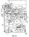
- the other end of each drive rod 128 is pivotally connected to a connecting link 131 via a coupling plate 131a and a pivot connection 131c, shown in Figure 29 .
- the pivot connection 131c can include a bearing (not visible in the figures) surrounding a pin 131d within an apertured end 131 e of the connecting link 131.
- the pin 131d includes a cap, or carries a threaded nut, on each opposite end to secure the crank arm to the coupling plate 131a.
- Each drive rod 128 is carried within a guide tube 132 that is fixed between a wall 134 and a front bearing housing 133.
- the connecting links 131 are each pivotally connected to a crank arm 142 via a pin 141 that is journalled by a bearing 141 a that is fit within an end portion of the connecting link 131.
- the pin crank arm 142 is fixed to, and rotates with, a circular guard plate 135.
- the pin 141 has a cap, or carries a threaded nut, on each opposite end that axially fixes the connecting link 131 to the crank arm 142 and the circular guard plate 135.
- the connecting link 131 also includes a threaded portion 131 b to finely adjust the connecting link length.
- crank arms 142 are each driven by a right angle gear box 136 via a "T" gear box 137 having one input that is driven by a precise position controlled motor 138 and two outputs to the gearboxes 136.
- the "T" gear box 137 and the right angle gear boxes 136 are configured such that the crank arms 142 rotate in opposite directions at the same rotary speed.
- the precise position controlled motor can be a 6-7.5 HP totally enclosed fan cooled servo motor.
- the servo motor is provided with two modules: a power amplifier that drives the servo motor, and a servo controller that communicates precise position information to the machine controller.
- the controller and the servo motor 138 are preferably configured such that the servo motor rotates in an opposite rotary direction every cycle, i.e., clockwise during one cycle, counterclockwise the next cycle, clockwise the next cycle, etc.
- a bearing housing 143 is supported on each gearbox 136 and includes a rotary bearing 143a therein to journal an output shaft 136a of the gear box 136.
- the output shaft 136a is fixed to the crank arm 142 by a clamp arrangement formed by legs of the crank arm 142 that surround the output shaft and have fasteners that draw the legs together to clamp the output shaft between the legs (not shown), and a longitudinal key (not shown) fit into a keyway 136b on the output shaft and a corresponding keyway in the crank arm 142 (not shown).
- a tie bar 139 is connected between the rods 128 to ensure a parallel reciprocation of the rods 128.
- the crank arms 142 rotate in opposite rotational directions, the outward centrifugal force caused by the rotation of the crank arms 142 and the eccentric weight of the attached links 131 cancels, and separation force is taken up by tension in the tie bar 139.
- One circular guard plate 135 is fastened on top of each crank arm 142.
- the pin 141 can act as a shear pin. If the mold plate should strike a hard obstruction, the shear pin can shear by force of the crank arm 142.
- the guard plate 135 prevents an end of the link 131 from dropping into the path of the crank arm 142.
- the drive mechanism of the mold plate is easily reconfigured to change stroke length of different mold plates. For example, 6, 7, 8, 9, 10 or 11 inch stroke lengths are practically achievable with the apparatus by changing parts, such as the parts 131, 135, 142.
- the molding mechanism 28 is assembled as shown in Figures 2 and 9A , with cover plate 122 tightly clamped onto spacers 124.
- knockout cups 33 are first withdrawn to the elevated position as shown in Figure 9F .
- the drive for mold plate 32 then slides the mold plate from the full extended position to the mold filling position illustrated in Figures 2 and 9A , with the mold cavities 126 aligned with passageway 111.
- the knockout mechanism remains in the elevated position, shown in Figure 9A , with knockout cups 33 clear of mold plate 32.
- mold plate 32 reaches its extended discharge position as shown in Figure 9F the knockout cups 33 are driven downward to discharge the patties from the mold cavities.
- the discharged patties may be picked up by the conveyor 29 or may be accumulated in a stacker. If desired, the discharged patties may be interleaved with paper, by an appropriate paper interleaving device.
- a paper interleaving device is disclosed in U.S. Patent 3,952,478 , or U.S. Serial No. 60/540,022, filed on January 27, 2004 .
- machine 20 may be used with a wide variety of secondary equipment, including steak folders, bird rollers, and other such equipment.
- the mold plate motion can be precisely controlled.
- the motion can have a fully programmable dwell, fill time, and advance and retract speeds.
- the preferred embodiment apparatus 20 of the present invention utilizes an exemplary frame 500 as illustrated in Figures 2 , 3 , 5-8 and 26 .
- the frame 500 includes a thick base plate 21a.
- the base plate 21 a comprises a stainless steel plate, 1 ⁇ 2 inch thick.
- Two rear anchors 506a, 506b and two forward anchors 508a, 508b are fastened to the base plate 21 a with fasteners and keys (not shown) a rectangular pattern.
- the base plate 21a and the anchors have recesses or keyways to receive the keys.
- Two rear struts 510a, 510b extend obliquely forward in parallel from the rear anchors 506a, 506b and are fastened thereto using fasteners and shims.
- Two forward struts 510a, 510b extend obliquely rearward in parallel from the front anchors 508a, 508b and are fastened thereto using fasteners and shims.
- each rear strut 510a, 510b comprises a rectangular tube column 510c having a plate flange 510d, 510e welded to each end thereof.
- the tube columns preferably have 3 inch by 2 inch by 1 ⁇ 4 inch thick cross sections.
- the bottom plate flange 510d is fastened to the respective anchor 506a, 506b using fasteners and shims.
- Each anchor includes a central stud threaded into the anchor and abutting the respective base plate and used for positioning and spacing the bottom flange 510d so that the shims may be installed before the strut is fastened to the anchor.
- the top plate flange 510e is fastened to a vertical backing plate 516 using fasteners and a key fit into keyways in the flange 510e and the backing plate 516.
- each of forward struts 512a, 512b comprises a rectangular tube column 512c having a plate flange 512d welded to each bottom end thereof and a block flange 512e welded to each top end thereof.
- the tube columns preferably have 3 inch by 2 inch by 1 ⁇ 4 inch thick cross sections.
- Each bottom plate flange 512d is fastened to a respective anchor 508a, 508b.
- the top block flanges 512e, 512e are fastened to a respective connection block 520a, 520b, by a tie rod 522a, 522b that is threaded into the respective block flange 512e.
- the connection blocks 520a, 520b are fastened to the manifold 27.
- the tie rods 522a, 522b are surrounded by respective surrounding sleeves or spacers 524a, 524b located between respective connection block 520a, 520b and the vertical backing plate 516.
- the tie rod 522a, 522b are tensioned by nuts 525a, 525b via tie backing blocks 526a, 526b.
- the spacers 524a, 524b are compressed between the connection blocks 520a, 520b and the backing plate 516 when the nuts 525a, 525b are tightened.
- the tie rods 522a, 522b are preferably 1 1 ⁇ 4 inch in diameter and the spacers are 2 3 ⁇ 4 inch in outside diameter.
- connection blocks 520a, 520b are supported by internal columns 530a, 530b that are fastened to the base plate 21 a ( Figures 2 and 13) and the block flanges 512e.
- the internal columns 530a, 530b are preferably square tubes having a 2 inch by 2 inch by 1 ⁇ 4 inch thick cross section.
- the vertical backing plate 516 is supported by a wall 532 provided within the machine base 21. The plate 516 is fastened to the wall 532.
- a pair of columns 531 a, 531 b supports the manifold 27 at a front of the machine ( Figures 2 , 8 ).
- the columns are formed by tie rods 531 c surrounded by tubular spacers 531 d.
- the tie rods 531 c are fastened to the anchors 508a, 508b using nuts 531 e.
- the upper end of the tie rod can be threaded into the manifold 27.
- the tubular spacer is compressed between the manifold 27 and the respective anchor 508 a, 508b when the nuts 531 e are tightened.
- tie rods As shown in Figures 3 and 6 , three more tie rods, with associated spacers or sleeves are used.
- Two top level tie rods 532a, 532b, surrounded by spacers or sleeves 536a, 536b, and located laterally outside the pump cavities 69, 89 are threaded into threaded bores in the pump housing 71.
- the tie rods 532a, 532b are tensioned with nuts 537a, 537b on a rear side of backing plate 516, via the backing blocks 526a, 526b.
- the tie rods when tensioned, compress the spacers or sleeves 525a, 525b, 536a, 536b and 542 tightly between the backing plate 516 and the pump housing 71 and the connection blocks 520a, 520b which are fastened to, or formed as part of the manifold housing 71.
- the tie rods 532a, 532b, 540 have a diameter of 1 1 ⁇ 4 inch and the spacers 536a, 536b and 542 have a 2 3 ⁇ 4 inch outside diameter.
- the hydraulic cylinders 64, 84 have front flanges 64a, 84a bolted to the backing plate 516 via two reinforcing washer plates 548a, 548b.
- a reaction force is created that tends to separate the backing plate 516 from the pump housing 71.
- the five tie rods oppose this reaction force by tension in the tie rods. Because the tie rods take up this reaction force, instead of the machine frame, the associated stress within the machine frame is reduced, or eliminated.
- the T gear box 137 is supported from a pedestal 568 on a support plate 570.
- the right angle gearboxes 136 are also supported from pedestals 569 fastened to the plate 570 ( Figure 29 ).
- the support plate 570 is fastened to a bottom of two vertically oriented, parallel, longitudinally arranged plates 571, 572.
- the plates 571, 572 are supported at a rear by being fastened to a crossbeam 574 that is supported by sidewalls of the machine base 21.
- the longitudinally arranged plates 571, 572 are laterally braced by a cross brace 577.
- the plates 571, 572 extend to the backing plate 516 and are fastened thereto by being fastened to the backing blocks 526a, 526b respectively by fasteners 573, locating pins 573a, and keys 573b fit into corresponding keyways in the blocks 526a, 526b and the plates 571, 572 ( Figure 26 ).
- the backing plate 516 has a thickness of 1 1 ⁇ 4 inches.
- the plates 571, 572 can have thicknesses of 3 ⁇ 4 inches and heights of 13 1 ⁇ 4 inches.
- the support plate 570 can have a thickness of 11 ⁇ 4 inches.
- the bearing housings 143 that are located above each right angle gear box 136, are connected by pre-stressed tie rods 580a, 580b to the backing plate 516.
- the tie rods 580a, 580b are threaded into tapped holes in the backing plate 516 and secured to each respective housing 143 by a nut 581.
- a vertical, rectangular opening 143d is provided through each bearing housing 143 to access the nuts 581 ( Figure 29 ).
- Each nut 581 is threaded onto an end of one rod 580a, 580b and tightened against the respective bearing housing 143.
- the tie rods 580a, 580b are surrounded by respective tubes 582a, 582b.
- the tubes 582a, 582b are compressed between a respective housing 143 and the backing plate 516 when the nuts 581 are tightened onto the tie rods 580a, 580b.
- the tie rods 580a, 580b, and the tubes 582a, 582b fix the bearing housings 143 with respect to the backing plate 516.
- the tie rod 580b and tube 582b are not shown in Figure 29 but are identically configured and attached in parallel fashion as the tie rod 580a, 582a.
- the tie rods have a diameter of 3 ⁇ 4 inches.
- the individual struts 510a, 510b, 512a, 512b are removable given the fact that they are fastened in place using fasteners and can be removed from the machine base 21 and replaced. This is particularly advantageous during assembly and replacement of other components, wherein the struts can be removed for access to other components within the machine base 21.
- All of the internal structural members can be composed of structural steel, except the base plate 21 a is preferably composed of stainless steel and the pump housing 71 and manifold 27 are preferably composed of stainless steel.
- the pump housing 71 and the valve manifold 27 can be a single cast stainless steel part. By forming these parts as a unitary part, significant assembly time is reduced, and the machine part count is reduced.
- the hopper 25 can be constructed as a unitary, one piece part comprised of a 0.09 inch thick welded and polished stainless steel part.
- a one piece hopper is advantageous to reduce leakage.
- the hopper 25 is supported at a rear by a hinge shaft 602 via a rear bracket 604 that is fastened to a rear wall 25d of the hopper 25.
- the bracket 604 is fixed to the hinge shaft 602 to rotate therewith.
- the fixing can be by a press fit engagement, a keyed arrangement between the bracket and the shaft, or by the bracket being fastened to the shaft with fasteners, or by another known non-rotation fixation method.
- the hinge shaft 602 is supported from the machine base 21 and journaled for rotation by a rear support 606 ( Figures 4 and16) and by a front support 608 ( Figure 5 ).
- the rear support 606 includes a roller bearing 612 that surrounds the hinge shaft 602 and provides for a reduced-friction rotation of the hinge shaft.
- the front support 608 comprises a sleeve bearing that provides for a reduced-friction rotation of the hinge shaft.
- the hopper 25 and feed screw frame 42 are fixed to the shaft 602 by a bracket 610 that includes two bosses 610a each with a bore 610b.
- the bracket 610 is fixed to rotate with the shaft 602 by use of a non-circular, hexagonal opening (not shown) in the bracket 610 that fits tightly over a correspondingly shaped end protrusion 611 b ( Figure 4 ) of the shaft 602.
- the bracket is then tightly clamped to the shaft by a bolt 609 and a washer 609b ( Figures 4 and 5 ), the bolt 609 engaged into a threaded bore in the protrusion 611 b.
- the bracket 610 is fixed to the frame 42 by the bosses 610a being fit within a gap along the spacers 44b of the front two spacers 44b and the associated tie rods 44a being inserted through the bosses 610a and spacers 44b and then tightened.
- the tie rods 44a are tightened via threaded inserts 613a to a horizontal plate 613 that forms part of the hopper assembly.
- crank lever 614 is provided that is keyed by a key 614a to the shaft 602.
- a large threaded lock nut or lock collar 615 is threaded tightly onto a threaded end of the shaft and locked with a set screw 615a.
- the crank lever 614 is pivotally connected at a distal end to an actuator, such as a hydraulic cylinder 616.
- the cylinder 616 is pivotally connected at an opposite end thereof to an anchor lug 618 fixed to the base plate 21a.
- the cylinder is signal-connected via a hydraulic/electronic interface to the machine controller. Expansion of the cylinder 616 causes the crank lever 614 to be turned counterclockwise ( Figure 16 ) by about 85 degrees to the position shown as 614aa.
- the shaft 602 is thus turned about 85 degrees, as is the hopper 25 to the position marked 25aa.
- the conveyor belt 31 is exposed for cleaning or removal.
- the plate 613 being a part of the hopper assembly, pivots with the hopper 25, as does the frame 42.
- the conveyor 30 includes a frame 619 having a hinge-side sidewall 620, an opposite-side sidewall 621, a plurality of lateral tie rods 622, a plurality of longitudinal ribs 623 supported on the tie rods 622, and two lateral tie rod beams 624, 625.
- the lateral tie rods 622 and the tie rod beams 624, 625 each have surrounding sleeves or spacers between the sidewalls 620, 621 and are fixed at opposite ends by nuts or the like to the sidewalls 620, 621.
- the conveyor frame 619 is simply supported on the machine base along the opposite-side sidewall 621.
- Two intermediate fixtures 636, 638 ( Figure 4 ) are welded or otherwise fixed to the wall 620 of the conveyor and surround the shaft 602.
- the intermediate fixtures 636, 638 are rotatable with respect to the shaft 602 about the axis of the shaft 602.
- the fixtures 636, 638 have cross pins 640, 642 respectively.
- the fixtures are in two pieces that are assembled around the shaft using fasteners (not shown).
- the conveyor can be cleaned or repaired as required.
- the surface area beneath the conveyor belt can be cleaned as well.
- the conveyor belt 31 can be removed and/or cleaned.
- the 85 degree hopper tilt and 13 degree conveyor tilt are advantageous, it is anticipated that other angular tilts such as 45 degrees - 90 degrees for the hopper and 10 degrees - 30 degrees for the conveyor may be advantageous as well.
- the location and size or shape of the pins 644, 646 can be adjusted to select the hopper and conveyor tilt amounts.
- the hopper 25 and conveyor 30 are pivoted by the actuator 616 via the machine controller, particularly by instructions give to the controller via the control panel 19.
- the hopper tilt system is configured such that apparatus can be easily factory converted from a right side operating apparatus to a left side operating apparatus, that is, the hopper assembly is factory reversible across the longitudinal centerline of the apparatus.
- the crank lever 614 comprises a lever arm 614b that is welded to a collar 614c that is secured to the shaft 602.
- the lever arm 614b can easily be switched for a right side operation by flipping over the lever arm and welding the lever arm the collar.
- the remaining shaft supports and brackets can be reused for mounting the system on the opposite side of the machine. Parts needing to be designed and manufactured can be reduced; given the bidirectional feature of the design.
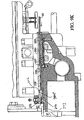
- the present invention also provides an improved cooling air system.
- the cooling air system includes two axial fans 702, 704 shown in Figure 16 and 29 that draw air in on a top side and discharge air downward into the machine base 21.
- the fans 702, 704 are mounted on elevated baffle plate 706 within a fan chamber 708.
- the baffle plate 706 provides openings beneath the fans 702, 704, for axial airflow into the machine base 21.
- the fan chamber includes a rectangular surrounding side wall 710 having a seal 712 around its upper lip.
- a cover 716 is provided over top side wall 710.
- the cover 716 is movable up-and-down.
- the cover 716 is shown in broken fashion to illustrate the movement of the cover 716. It is understood however that the cover 716 is one part and is either raised her lowered as one part.
- the elevated position of the cover 716 is indicated as 716a shown on the right side half of the cover 716 and the lowered position is indicated as 716b shown on the left side half of the cover.
- the pneumatic cylinders 722, eight are fastened at base ends to the baffle plate 706.
- the pneumatic cylinders include extendable rods 726 that are fastened to the cover 716.
- the cylinders 722 are configured such that when energized with pressurized air the cylinders extend rods 726 to elevate the cover 716 to the position indicated as 716a, held above the seal 712. Outside air can be admitted under the cover and up and over the seal 712 to the inlet of the fans 702, 704 as indicated by the arrows "A.”
- the cylinders 722 overcome the compression force of springs 730 within the cylinders 722 to elevate the cover 716 as shown in position 716a. If the cylinders 722 are de-energized, such as by loss of electrical power to the apparatus 20, the springs 730 urge the cover 716 downward onto the seal 712, as shown in position 716b, to close the inlet.
- the cylinders 722 are energized, and the cover 716 is elevated as shown in position 716a.
- the fans 702, 704 force air through the machine base 21.
- two air exit dampers 740, 742 are provided having shut off plates 744, 746.
- the shut off plates 744, 746 are positioned over air openings 750, 752 through the base plate 502.
- the plates 744, 746 are carried by rods 754, 756 via self aligning couplings 754a, 756a and are raised and lowered by cylinders 758, 760.
- the cylinders are supported by a bracket 764 from the machine base 21 or other stationary structure.
- cylinders 758, 760 are springs (not shown) that are configured to urge the plates 744, 746 downward from the elevated, open position indicated as 744a, 746a to the lowered, closed position indicated as 744b, 746b.
- cylinders 758, 750 are energized and pneumatic pressure elevates the plates 744, 746 to the position 744a, 746a, overcoming the urging of the springs within the cylinders 758, 760.
- the plates 744, 746 are lowered by the springs within the cylinders 758, 760 to close the air exit dampers 740, 742.
- the hopper tilt system, the control panel 23, and the cooling air system are configured such that apparatus can be easily factory converted from a right side operating apparatus to a left side operating apparatus, that is, factory reversible across the longitudinal centerline of the apparatus.
- the apparatus incorporates a hydraulic system such as described in U.S.
- Patent 3,887,964 or Re 30, 096 or as currently used on FORMAX F-26 machines.
- a lower pressure, higher volume hydraulic pump and a higher pressure, lower volume hydraulic pump are used.
- the lower pressure pump is useful for moving the hydraulic piston and the associated plunger a large distance such as from a retracted position to a position wherein the food product is initially compressed within the cylinder by the plunger.
- the higher pressure pump is useful to move the plunger an incremental distance each mold plate reciprocation cycle, to deliver food product under pressure into the mold cavities.
- One improvement in the present invention is the fact that the lower pressure pump 1410 and the higher pressure hydraulic pump 1414 are both driven by a common electric motor 1416, in series on the motor output shaft, wherein the pumps 1410, 1414 are located in the hydraulic fluid reservoir 1418, submerged below a hydraulic fluid fill line 1417. By being submerged, the pumps run quieter, cooler and more efficiently.
- the motor 1416 is preferably a 15 HP totally enclosed, fan cooled motor. As shown in Figure 29 the motor 1416 is supported on a platform 1416a that is supported in cantilever fashion from the reservoir 1418. The motor includes a rotary output shaft 1416b.
- the reservoir 1418 is preferably a stainless steel tank. A bottom 1419 of the reservoir is advantageously visible for inspection and cleaning and sanitizing.
- the reservoir 1418 can be elevated from the base 21 a on isolation mounts.
- the pumps 1410 and 1414 have pump shafts 1424a, 1424b connected by a coupling 1424c, shown dashed.
- the pump shaft 1424a is coupled to the motor output shaft 1416b by a mechanical coupling 1426.
- a motor mount 1430 surrounds the coupling 1426 as it is sealed to a wall 1418a of the reservoir 1418 by a ring seal (not shown) clamped between a backing ring (not shown) that is fastened through the wall 1418a to the motor mount 1430.
- the lower pressure pump 1410 is bolted to the backing ring in sealed fashion.
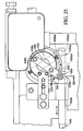
- a mold housing lift mechanism 800 is mounted inside the machine base 21 and extends upward to the housing 123.
- the lift mechanism includes two jacks 802, 804 shown in Figure 8 .
- the jacks are operatively connected to right angle drives 808, 810, which are operatively connected to a T type right angle drive 814, via drive shafts 818, 820 and respective couplings 823, 824, 826, 828, 830.
- the right angle drive 814 is driven into rotation by a hydraulic motor 836.
- the jack 802 is described below with the understanding that the jack 804 is identically configured and functions identically, in tandem, as the jack 802.
- the drive 808 turns a threaded rod or jackscrew 842 that drives a nut drive assembly 844 vertically.
- the jack screw 842 is journaled for rotation at a top end by a guide 845.
- the jack screw 842 and guide 845 can include a bearing therebetween for smooth journaled rotation of the jackscrew.
- the drive assembly 844 is operatively connected to a lift column 850 via a bracket 851 which is vertically driven with the drive nut assembly.
- the columns 850 of the jacks 802, 804, are fixed to the housing 123 by bolts 856, 858.
- the columns 850 are hollow and can also serve as wire and tube conduits.
- the bracket 851 is clamped onto a bottom of column 850.
- the bracket 851 rests on a drive nut 870 that is driven by the drive rod 842.
- a limit plate 862 is fastened to the drive nut 870 by spacers 867 and fasteners 866.
- a collar 874 is fastened to the bottom of the drive nut 870 with fasteners 875.
- the drive nut 870 has inside threads engaged to the outside threads of the drive rod 842.
- a secondary nut 882 is threaded onto the jackscrews 842 beneath the drive nut 870.
- Proximity target magnetic plate 892 is fastened to a mounting plate 894 which is fastened to the bracket 851 by fasteners 900.
- a proximity sensor 908 is mounted within the machine base 21 along the vertical path of the magnetic plate 892 and set at a maximum acceptable. The magnetic plate 892 sets an acceptable vertical range for a mold cover operating elevation. If the mold cover is elevated beyond this range, the sensor 908 will be below the magnetic plate 892 and will so signal the machine controller which will prevent operation of the machine.
- a further proximity target 904 is fastened to a lateral side of the bracket 851.
- Proximity sensor 910 is mounted at an elevated position within the machine base along the vertical path of the target 904 and signals a pre-determined raised maximum height of the mold cover casting for a mold plate change out procedure.
- the proximity sensor 910 signals the machine controller to stop the motor 836 at that point.
Landscapes
- Engineering & Computer Science (AREA)
- Life Sciences & Earth Sciences (AREA)
- Food Science & Technology (AREA)
- Wood Science & Technology (AREA)
- Zoology (AREA)
- Manufacturing & Machinery (AREA)
- Chemical & Material Sciences (AREA)
- Polymers & Plastics (AREA)
- Formation And Processing Of Food Products (AREA)
- Manufacturing And Processing Devices For Dough (AREA)
- Confectionery (AREA)
- Meat, Egg Or Seafood Products (AREA)
- Devices For Dispensing Beverages (AREA)
- Details Of Reciprocating Pumps (AREA)
- Basic Packing Technique (AREA)
- Lift Valve (AREA)
- Valve Housings (AREA)
- Processing Of Meat And Fish (AREA)
Description
- Use of pre-processed foods, both in homes and in restaurants, has created a demand for effective high-capacity automated food processing equipment. That demand is particularly evident with respect to hamburgers, molded steaks, fish cakes, and other molded food patties.
- Food processors utilize high-speed molding machines, such as FORMAX F-6, F-12, F-19, F-26 or F-400 reciprocating mold plate forming machines, available from Formax, Inc. of Mokena, Illinois, U.SA., for supplying patties to the fast food industry. Prior known high-speed molding machines are also described for example in
U.S. patents 3,887,964 ;4,372,008 ;4,356,595 ;4,821,376 ; and4,996,743 . - Although heretofore known FORMAX patty-molding machines have achieved commercial success and wide industry acceptance, the present inventors have recognized that needs exist for a forming machine having an even greater energy efficiency, an even greater durability and an even greater duration of maintenance free operation. The present inventors have recognized that needs exist for an enhanced controllability and ability to tune a patty-forming machine for particular food materials to be processed, for an enhanced effectiveness of a patty-forming machine in producing uniform patties, for an even greater output rate of patties from a patty-forming machine, for an enhanced convenience for cleaning and maintenance of a patty-forming machine, and for a smoother and quieter patty-forming machine operation.
- Further,
WO 99/62344 A - The present invention provides an improved cooling air system for a patty-forming apparatus having a machine base. The machine base includes an enclosing wall and contains equipment within the machine base that generates heat, such as electric motors, electrical and control equipment. The machine base includes an air inlet opening and an air outlet opening through the enclosing wall. At least one air fan is arranged to move outside air from the air inlet opening to the air outlet opening. A first air damper is arranged to close one of the air inlet opening or the air outlet opening. The first air damper is configured to automatically close if power is interrupted to the apparatus.
- According to a further enhancement of the invention, the first air damper is arranged to close the air inlet opening, and a second air damper is arranged to close the air outlet opening. The second air damper is also configured to automatically close if power is interrupted to the apparatus.
- Thus, when the machine is powered down for cleaning, the dampers automatically close the air intake and/or outlet openings. The fan will be powered off. This effectively battens down the machine base and prevents wash water, spray and contaminants from entering the machine base. Also, the fact that the machine is pressurized during operation by the fans can prevent some contaminants from entering the machine base during operation.
- Numerous omer advantages and features of the present invention will be become readily apparent from the following detailed description of the invention and the embodiments thereof, and from the accompanying drawings.
-
-
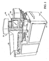
Figure 1 is a perspective view of a patty-forming machine of the present invention; -
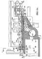
Figure 1A is an elevational view of the patty-forming machine ofFigure 1 ; -
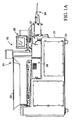
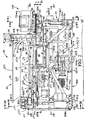
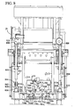
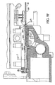
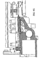
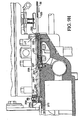
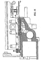
Figure 2 is a longitudinal sectional view of the patty-forming machine ofFigure 1 , with components and/or panels removed for clarity; -
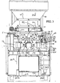
Figure 3 is a sectional view taken generally along line 3-3 ofFigure 2 , with components and/or panels removed for clarity; -
Figure 4 is a sectional view taken generally along line 4-4 ofFigure 2 , with components and/or panels removed for clarity; -
Figure 5 is a sectional view taken generally along line 5-5 ofFigure 2 , with components and/or panels removed for clarity; -
Figure 6 is a sectional view taken generally along line 6-6 ofFigure 2 , with components and/or panels removed for clarity; -
Figure 7 is a sectional view taken generally along line 7-7 ofFigure 2 , with components and/or panels removed for clarity; -
Figure 8 is a sectional view taken generally along line 8-8 ofFigure 2 , with components and/or panels removed for clarity; -
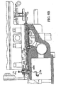
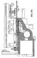
Figures 9A ,9F are enlarged fragmentary sectional views taken fromFigure 2 , showing the machine configuration as the mold plate is moved along its path of reciprocation; -
Figure 16 is a fragmentary sectional view taken generally along line 16-16 ofFigure 2 ; -
Figure 16A is a fragmentary sectional view taken generally along line 16A-16A ofFigure 16 ; -
Figure 26 is an enlarged, sectional view taken generally along line 26-26 ofFigure 2 ; -
Figure 29 is an enlarged, fragmentary sectional view taken from the left side ofFigure 2 ; -
Figure 30 is an enlarged, fragmentary sectional view taken from a front portion ofFigure 2 , with components and/or panels removed for clarity; -
Figure 31 is sectional view taken generally along line 31-31 ofFigure 30 ; - While this invention is susceptible of embodiment in many different forms, there are shown in the drawings, and will be described herein in detail, specific embodiments thereof with the understanding that the present disclosure is to be considered as an exemplification of the principles of the invention and is not intended to limit the invention to the specific embodiments illustrated.
- The high-speed food
patty molding machine 20 illustrated in the figures comprises an exemplary embodiment of the invention. This application refers toUS provisional application serial number 60/571,368, filed May 14, 2004 U.S. Application Serial No. 60/503,354, filed September 16, 2003 U.S. Provisional Application Serial No. 60/515,585, filed October 29, 2003 - The
molding machine 20 includes amachine base 21, preferably mounted upon a plurality offeet 22, rollers or wheels. Themachine base 21 supports the operating mechanism formachine 20 and can contain hydraulic actuating systems, electrical actuating systems, and most of the machine controls. The base can be clad in 3/16 inch stainless steel panels or skin. Themachine 20 includes asupply 24 for supplying moldable food material, such as ground beef, fish, or the like, to the processing mechanisms of the machine. - A
control panel 19, such as a touch screen control panel, is arranged on a forward end of theapparatus 20 and communicates with a machine controller (not shown). - As generally illustrated in
Figures 2 - 6 , supply means 24 comprises a large foodmaterial storage hopper 25 that opens into the intake of afood pump system 26. Thefood pump system 26 includes at least twofood pumps valve manifold 27 flow-connected to a cyclically operatedmolding mechanism 28. - In the operation of
machine 20, a supply of ground beef or other moldable food material is deposited intohopper 25 from overhead. An automated refill device (not shown) can be used to refill the hopper when the supply of food product therein is depleted. The floor ofhopper 25 at least partially closed by aconveyor belt 31 of aconveyor 30. Thebelt 31 includes atop surface 31 a for moving the food material longitudinally of thehopper 25 to a hopper forwardend 25a. - The food material is moved by supply means 24 into the intake of
plunger pumps pumping system 26. Thepumps system 26 operate in overlapping alteration to each other, and at any given time whenmachine 20 is in operation, at least one of the pumps is forcing food material under pressure into the intake ofmanifold 27. - The
manifold 27 comprises a path for feeding the food material, still under relatively high pressure, into themolding mechanism 28.Molding mechanism 28 operates on a cyclic basis, first sliding amulti-cavity mold plate 32 into a receiving position over manifold 27 (Figure 9A ) and then away from the manifold to a discharge position (Figure 9F ) aligned with a series of knock outcups 33. When themold plate 32 is at its discharge position, knock out cups plungers orcups 33 are driven downwardly as indicated by 33A inFigure 2 , discharging hamburgers or other molded patties frommachine 20. The molded patties are deposited onto a conveyor 29 (Figure 1A ), to be transported away from theapparatus 20. - The food supply means 24 and associated
hopper 25 are illustrated inFigures 2 - 6 . As seen, theconveyor belt 31 spans completely across the bottom ofhopper 25, around an end of idler roller orpulley 35 and drive roller orpulley 36, the lower portion of the belt being engaged by atensioning roller 37. In some cases the tensioningroller 37 may not be necessary, and can be eliminated. A drum motor (not visible) is provided within thedrive roller 36 for rotating the drive roller. - The
belt 31 can include a longitudinal V-shaped rib on an inside surface thereof that fits within a V-shaped cross sectional notch provided on therollers - The
forward end 25a ofhopper 25 communicates with avertical pump 38 having anoutlet 39 at least partly open into a pumpintake manifold chamber 41. A vertically orientedframe 42 extends abovehopper 25 adjacent the right-hand side of theoutlet 39. A motor housing 40 is mounted on top of theframe 42. Asupport plate 43 is affixed to the upper portion offrame 42 extending over theoutlet 39 inhopper 25. The frame comprises fourvertical tie rods 44a surrounded byspacers 44b (Figure 5 ). - As shown in
Figure 5 , thevertical pump 38 comprises twofeed screw motors feed screw motors support plate 43, within the motor housing 40.Motor 45 drives thefeed screw 51 that extends partly through opening 39 in alignment with apump plunger 66 of thepump 61.Motor 46 drives thefeed screw 52 located at the opposite side ofhopper 25 fromfeed screw 51, and aligned with anotherpump plunger 68 of thepump 62. - When
machine 20 is in operation, thefeed screw motor 45 is energized wheneverplunger 66 is withdrawn to the position shown inFigure 2 , so thatfeed screw 51 supplies meat fromhopper 25 downwardly throughoutlet 39 into one side of theintake 41 of thefood pumping system 26. Similarly,motor 46 actuates the feed screws 52 to feed meat to the other side ofintake 41 wheneverplunger 68 of thepump 62 is withdrawn. In each instance, thefeed screw motors outlet 39 is depleted, theconveyor belt 31 continuously moves food forwardly in the hopper and into position to be engaged by the feed screws 51, 52. If the level of meat at theoutlet 39 becomes excessive,conveyor 30 is stopped, as described above, until the supply at the hopper outlet is again depleted. - The wall of the
outlet 39 immediately belowconveyor drive rollers 36 comprises abelt wiper plate 57 that continuously engages the surface of theconveyor belt 31 to prevent leakage of thefood material 38 from the hopper at this point. - The
food pump system 26 of moldingmachine 20 is best illustrated inFigures 2 and6 .Pump system 26 comprises the two reciprocating food pumps 61, 62 mounted within themachine base 21. Thefirst food pump 61 includes ahydraulic cylinder 64. The piston (not shown) incylinder 64 is connected to anelongated piston rod 67; the outer end of theelongated piston rod 67 is connected to thelarge plunger 66. Theplunger 66 is aligned with afirst pump cavity 69 formed by a pump cavity enclosure or pumphousing 71. Theforward wall 74 ofpump cavity 69 has a relativelynarrow slot 73 that communicates with thevalve manifold 27 as described more fully hereinafter. - Preferably, the
pump housing 71 and thevalve manifold 27 are cast or otherwise formed as a one piece stainless steel part. - The
second food pump 62 is essentially similar in construction to pump 61 and comprises ahydraulic cylinder 84.Cylinder 84 has an elongatedpiston rod 87 connected to thelarge plunger 68 that is aligned with asecond pump cavity 89 formed inhousing 71. Theforward wall 94 ofpump cavity 89 includes a narrowelongated slot 93 communicating withmanifold 27. - Advantageously, the
plungers pump cavities - An elongated proximity meter 75 is affixed to the
first pump plunger 66 and extends parallel topiston rod 67 into alignment with a pair ofproximity sensors similar proximity meter 95 is fixed to and projects fromplunger 68, parallel topiston rod 87, in alignment with a pair ofproximity sensors Proximity sensors pumps Figure 6 . - The
meters 75, 95 andsensors controller 23, or in intervening electronics and communicated to thecontroller 23. - Two
further proximity sensors meters 75, 95 respectively, are provided which communicate to the controller or to intervening electronics that communicate with the controller, the home position of the respective plunger which corresponds to a front end of each plunger being just inside, and sealed by a front ring seal 99 (Fig. 2 ) to thepump housing 71. The home position of each plunger is used by the controller to calibrate or set the machine position control of theplungers - In operation, the
first pump 61 pumps the moldable food material intomanifold 27 and thesecond pump 62 receives a supply of the moldable food material for a subsequent pumping operation.Pump 61 begins its pumping stroke, and compresses food product inpump cavity 69, forcing the moldable food material throughslot 73 intomanifold 27. As operation of moldingmachine 20 continues, pump 61 advances plunger 66 to compensate for the removal of food material throughmanifold 27. The pump can maintain a constant pressure on the food material in thecavity 69 during the molding cycle, or preferably can provide a pre-selected pressure profile over the molding cycle such as described inU. S. Patent 4,356, 595 , or as utilized in currently available FORMAX machines. The pressure applied throughpump 61 is sensed by apressure sensing switch 78 connected to a port of thecylinder 64. - As
plunger 66 advances, the corresponding movement of proximity meter 75 signals thesensor 76, indicating thatplunger 66 is near the end of its permitted range of travel. When this occurs, pump 62 is actuated to advanceplunger 68 throughpump cavity 89, compressing the food material in the second pump cavity in preparation for feeding the food material from the cavity intomanifold 27. The pressure applied throughpump 62 is sensed by apressure sensing switch 79 connected to one port ofcylinder 84. - When the food in the
second pump cavity 89 is under adequate pressure, the input tomanifold 27 is modified so that subsequent feeding of food product to the manifold is effected from thesecond pump cavity 89 with continuing advancement ofplunger 68 of thesecond pump 62. After the manifold intake has been changed over, pump 61 is actuated to withdrawplunger 66 fromcavity 69. - Thereafter, when
plunger 68 is near the end of its pressure stroke intopump cavity 89,proximity sensor 96, signals the need to transfer pumping operations to pump 61. The changeover process described immediately above is reversed; pump 61 begins its compression stroke, manifold 27 is changed over for intake frompump 61, and pump 62 subsequently retractsplunger 68 back to the supply position to allow a refill ofpump cavity 89. This overlapping alternating operation of the twopumps machine 20 is in operation. - The
valve manifold 27, shown inFigures 2 and6 , holds a manifold valve cylinder ortube valve 101 fit into anopening 102 inhousing 71 immediately beyond thepump cavity walls - According to one embodiment,
valve cylinder 101 includes two longitudinally displacedintake slots 107 and 108 alignable with theoutlet slots pump cavity walls Slots 107 and 108 are angularly displaced from each other to preclude simultaneous communication between the manifold and both pumpcavities Cylinder 101 also includes anelongated outlet slot 109. The valvecylinder outlet slot 109 is generally aligned with a slot 111 (seeFigure 9A ) inhousing 71 that constitutes a feed passage formolding mechanism 28. - When the
pump 61 is supplying food material under pressure tomolding mechanism 28,actuator cylinder 106 has retractedpiston rod 105 to the inner limit of its travel, angularly orienting themanifold valve cylinder 101. Withcylinder 101 in this position, itsintake slot 107 is aligned with theoutlet slot 73 frompump cavity 69 so that food material is forced under pressure fromcavity 69 through the interior ofvalve cylinder 101 and out of the valvecylinder outlet slot 109 throughslot 111 to themolding mechanism 28. On the other hand, the second intake slot (not shown) ofvalve cylinder 101 is displaced from theoutlet slot 93 for thesecond pump cavity 89. Consequently, the food material forced into the interior ofvalve cylinder 101 frompump cavity 69 cannot flow back into theother pump cavity 89. - When reloading the pump box with product, the following occurs. For example, when reloading the
pump cavity 89 forplunger 68, theplunger 68 retracts and the feed screws rotate. The combination of the vacuum created by theplunger 68 withdrawing from the pumping chamber, and the turning screws, forces food product in front of theplunger 68. The plunger is then advanced into thechamber 89 to initially compress the food product before filling begins. As theplunger 68 advances to thepump chamber 89, there will be air inter-mixed with food product. This air must be removed before theplunger 68 starts its mold plate cavity-filling cycle. - As best illustrated in
Figure 9A , the upper surface of thehousing 71 that encloses thepump cavities plate 121 and afill plate 121 a that forms a flat, smooth mold plate support surface. Themold support plate 121 and thefill plate 121 a may be fabricated as two plates as shown, or a single plate bolted to or otherwise fixedly mounted uponhousing 71. Thefill plate 121 a includes apertures or slots that form the upper portion of themanifold outlet passage 111. In the apparatus illustrated, a multi fill orificetype fill plate 121 a is utilized. A simple slotted fill plate is also encompassed by the invention. -
Mold plate 32 is supported uponplates Mold plate 32 includes a plurality ofindividual mold cavities 126 extending across the width of the mold plate and alignable with themanifold outlet passageway 111. Although a single row of cavities is shown, it is also encompassed by the invention to provide plural rows of cavities, stacked in aligned columns or in staggered columns. Acover plate 122 is disposed immediately abovemold plate 32, closing off the top of each of themold cavities 126. A mold cover casting orhousing 123 is mounted uponcover plate 122. The spacing betweencover plate 122 andsupport plate 121 is maintained equal to the thickness ofmold plate 32 bysupport spacers 124 mounted uponsupport plate 121.Cover plate 122 rests uponspacers 124 when the molding mechanism is assembled for operation.Cover plate 122 andmold cover 123 are held in place by six mounting bolts, or nuts tightened on studs, 125. - As best illustrated in
Figures 3 and6 ,mold plate 32 is connected to driverods 128 that extend alongsidehousing 71 and are connected at one end to atransverse bar 129. The other end of eachdrive rod 128 is pivotally connected to a connectinglink 131 via a coupling plate 131a and a pivot connection 131c, shown inFigure 29 . The pivot connection 131c can include a bearing (not visible in the figures) surrounding apin 131d within an apertured end 131 e of the connectinglink 131. Thepin 131d includes a cap, or carries a threaded nut, on each opposite end to secure the crank arm to the coupling plate 131a. - Each
drive rod 128 is carried within aguide tube 132 that is fixed between awall 134 and afront bearing housing 133. The connectinglinks 131 are each pivotally connected to a crankarm 142 via apin 141 that is journalled by a bearing 141 a that is fit within an end portion of the connectinglink 131. The pin crankarm 142 is fixed to, and rotates with, acircular guard plate 135. Thepin 141 has a cap, or carries a threaded nut, on each opposite end that axially fixes the connectinglink 131 to thecrank arm 142 and thecircular guard plate 135. The connectinglink 131 also includes a threaded portion 131 b to finely adjust the connecting link length. - The crank
arms 142 are each driven by a rightangle gear box 136 via a "T"gear box 137 having one input that is driven by a precise position controlledmotor 138 and two outputs to thegearboxes 136. The "T"gear box 137 and the rightangle gear boxes 136 are configured such that the crankarms 142 rotate in opposite directions at the same rotary speed. - The precise position controlled motor can be a 6-7.5 HP totally enclosed fan cooled servo motor. The servo motor is provided with two modules: a power amplifier that drives the servo motor, and a servo controller that communicates precise position information to the machine controller.
- The controller and the
servo motor 138 are preferably configured such that the servo motor rotates in an opposite rotary direction every cycle, i.e., clockwise during one cycle, counterclockwise the next cycle, clockwise the next cycle, etc. - A bearing
housing 143 is supported on eachgearbox 136 and includes a rotary bearing 143a therein to journal an output shaft 136a of thegear box 136. The output shaft 136a is fixed to thecrank arm 142 by a clamp arrangement formed by legs of thecrank arm 142 that surround the output shaft and have fasteners that draw the legs together to clamp the output shaft between the legs (not shown), and a longitudinal key (not shown) fit into a keyway 136b on the output shaft and a corresponding keyway in the crank arm 142 (not shown). - A
tie bar 139 is connected between therods 128 to ensure a parallel reciprocation of therods 128. As the crankarms 142 rotate in opposite rotational directions, the outward centrifugal force caused by the rotation of thecrank arms 142 and the eccentric weight of the attachedlinks 131 cancels, and separation force is taken up by tension in thetie bar 139. - One
circular guard plate 135 is fastened on top of each crankarm 142. Thepin 141 can act as a shear pin. If the mold plate should strike a hard obstruction, the shear pin can shear by force of thecrank arm 142. Theguard plate 135 prevents an end of thelink 131 from dropping into the path of thecrank arm 142. - The drive mechanism of the mold plate is easily reconfigured to change stroke length of different mold plates. For example, 6, 7, 8, 9, 10 or 11 inch stroke lengths are practically achievable with the apparatus by changing parts, such as the
parts - During a molding operation, the
molding mechanism 28 is assembled as shown inFigures 2 and9A , withcover plate 122 tightly clamped ontospacers 124. - In each cycle of operation, knockout cups 33 are first withdrawn to the elevated position as shown in
Figure 9F . The drive formold plate 32 then slides the mold plate from the full extended position to the mold filling position illustrated inFigures 2 and9A , with themold cavities 126 aligned withpassageway 111. - During most of each cycle of operation of
mold plate 32, the knockout mechanism remains in the elevated position, shown inFigure 9A , withknockout cups 33 clear ofmold plate 32. Whenmold plate 32 reaches its extended discharge position as shown inFigure 9F the knockout cups 33 are driven downward to discharge the patties from the mold cavities. - The discharged patties may be picked up by the
conveyor 29 or may be accumulated in a stacker. If desired, the discharged patties may be interleaved with paper, by an appropriate paper interleaving device. Such a device is disclosed inU.S. Patent 3,952,478 , orU.S. Serial No. 60/540,022, filed on January 27, 2004 machine 20 may be used with a wide variety of secondary equipment, including steak folders, bird rollers, and other such equipment. - By using a servo motor to drive the mold plate, the mold plate motion can be precisely controlled. The motion can have a fully programmable dwell, fill time, and advance and retract speeds.
- The
preferred embodiment apparatus 20 of the present invention utilizes anexemplary frame 500 as illustrated inFigures 2 ,3 ,5-8 and26 . - The
frame 500 includes athick base plate 21a. Thebase plate 21 a comprises a stainless steel plate, ½ inch thick. Tworear anchors forward anchors base plate 21 a with fasteners and keys (not shown) a rectangular pattern. Thebase plate 21a and the anchors have recesses or keyways to receive the keys. - Two
rear struts rear anchors forward struts front anchors - As illustrated in
Figures 2 , 726, eachrear strut rectangular tube column 510c having aplate flange bottom plate flange 510d is fastened to therespective anchor bottom flange 510d so that the shims may be installed before the strut is fastened to the anchor. Thetop plate flange 510e is fastened to avertical backing plate 516 using fasteners and a key fit into keyways in theflange 510e and thebacking plate 516. - As illustrated in
Figures 2 , 75, each of forward struts 512a, 512b comprises arectangular tube column 512c having aplate flange 512d welded to each bottom end thereof and ablock flange 512e welded to each top end thereof. The tube columns preferably have 3 inch by 2 inch by ¼ inch thick cross sections. Eachbottom plate flange 512d is fastened to arespective anchor top block flanges respective connection block tie rod respective block flange 512e. The connection blocks 520a, 520b are fastened to themanifold 27. - The
tie rods spacers 524a, 524b located betweenrespective connection block vertical backing plate 516. Thetie rod tie backing blocks spacers 524a, 524b are compressed between theconnection blocks backing plate 516 when the nuts 525a, 525b are tightened. - The
tie rods - The connection blocks 520a, 520b are supported by
internal columns 530a, 530b that are fastened to thebase plate 21 a (Figures 2 and 13) and theblock flanges 512e. Theinternal columns 530a, 530b are preferably square tubes having a 2 inch by 2 inch by ¼ inch thick cross section. Thevertical backing plate 516 is supported by awall 532 provided within themachine base 21. Theplate 516 is fastened to thewall 532. - A pair of
columns 531 a, 531 b supports the manifold 27 at a front of the machine (Figures 2 ,8 ). The columns are formed by tie rods 531 c surrounded by tubular spacers 531 d. The tie rods 531 c are fastened to theanchors manifold 27. The tubular spacer is compressed between the manifold 27 and therespective anchor - As shown in
Figures 3 and6 , three more tie rods, with associated spacers or sleeves are used. Two toplevel tie rods sleeves pump cavities pump housing 71. Thetie rods backing plate 516, via thebacking blocks central tie rod 540 surrounded by a spacer orsleeve 542 and located laterally between thepump cavities pump housing 71 and is tensioned by anut 543 and washer pressed directly against thebacking plate 516. - The tie rods, when tensioned, compress the spacers or
sleeves backing plate 516 and thepump housing 71 and theconnection blocks manifold housing 71. - The
tie rods spacers - The
hydraulic cylinders front flanges 64a, 84a bolted to thebacking plate 516 via two reinforcingwasher plates hydraulic cylinders respective piston pump cavity backing plate 516 from thepump housing 71. The five tie rods oppose this reaction force by tension in the tie rods. Because the tie rods take up this reaction force, instead of the machine frame, the associated stress within the machine frame is reduced, or eliminated. - As shown in
Figures 3 and6 , theT gear box 137 is supported from apedestal 568 on asupport plate 570. Theright angle gearboxes 136 are also supported from pedestals 569 fastened to the plate 570 (Figure 29 ). Thesupport plate 570 is fastened to a bottom of two vertically oriented, parallel, longitudinally arrangedplates plates crossbeam 574 that is supported by sidewalls of themachine base 21. - The longitudinally arranged
plates cross brace 577. Theplates backing plate 516 and are fastened thereto by being fastened to thebacking blocks fasteners 573, locating pins 573a, and keys 573b fit into corresponding keyways in theblocks plates 571, 572 (Figure 26 ). - According to the preferred embodiment, the
backing plate 516 has a thickness of 1 ¼ inches. Theplates support plate 570 can have a thickness of 1¼ inches. - For additional rigidity, the bearing
housings 143 that are located above each rightangle gear box 136, are connected by pre-stressed tie rods 580a, 580b to thebacking plate 516. The tie rods 580a, 580b are threaded into tapped holes in thebacking plate 516 and secured to eachrespective housing 143 by a nut 581. A vertical, rectangular opening 143d is provided through each bearinghousing 143 to access the nuts 581 (Figure 29 ). Each nut 581 is threaded onto an end of one rod 580a, 580b and tightened against therespective bearing housing 143. The tie rods 580a, 580b are surrounded by respective tubes 582a, 582b. The tubes 582a, 582b are compressed between arespective housing 143 and thebacking plate 516 when the nuts 581 are tightened onto the tie rods 580a, 580b. The tie rods 580a, 580b, and the tubes 582a, 582b fix the bearinghousings 143 with respect to thebacking plate 516. The tie rod 580b and tube 582b are not shown inFigure 29 but are identically configured and attached in parallel fashion as the tie rod 580a, 582a. The tie rods have a diameter of ¾ inches. - According to one aspect of the invention, the
individual struts machine base 21 and replaced. This is particularly advantageous during assembly and replacement of other components, wherein the struts can be removed for access to other components within themachine base 21. - All of the internal structural members can be composed of structural steel, except the
base plate 21 a is preferably composed of stainless steel and thepump housing 71 andmanifold 27 are preferably composed of stainless steel. Thepump housing 71 and thevalve manifold 27 can be a single cast stainless steel part. By forming these parts as a unitary part, significant assembly time is reduced, and the machine part count is reduced. - The
hopper 25 can be constructed as a unitary, one piece part comprised of a 0.09 inch thick welded and polished stainless steel part. A one piece hopper is advantageous to reduce leakage. - As shown in
Figure 3 , thehopper 25 is supported at a rear by ahinge shaft 602 via arear bracket 604 that is fastened to arear wall 25d of thehopper 25. Thebracket 604 is fixed to thehinge shaft 602 to rotate therewith. The fixing can be by a press fit engagement, a keyed arrangement between the bracket and the shaft, or by the bracket being fastened to the shaft with fasteners, or by another known non-rotation fixation method. - As shown in
Figures 4 ,5 ,16 , 27 and29 , thehinge shaft 602 is supported from themachine base 21 and journaled for rotation by a rear support 606 (Figures 4 and16) and by a front support 608 (Figure 5 ). Therear support 606 includes aroller bearing 612 that surrounds thehinge shaft 602 and provides for a reduced-friction rotation of the hinge shaft. Thefront support 608 comprises a sleeve bearing that provides for a reduced-friction rotation of the hinge shaft. - As shown in
Figure 5 thehopper 25 and feedscrew frame 42 are fixed to theshaft 602 by abracket 610 that includes twobosses 610a each with abore 610b. Thebracket 610 is fixed to rotate with theshaft 602 by use of a non-circular, hexagonal opening (not shown) in thebracket 610 that fits tightly over a correspondingly shaped end protrusion 611 b (Figure 4 ) of theshaft 602. The bracket is then tightly clamped to the shaft by abolt 609 and a washer 609b (Figures 4 and5 ), thebolt 609 engaged into a threaded bore in the protrusion 611 b. Thebracket 610 is fixed to theframe 42 by thebosses 610a being fit within a gap along thespacers 44b of the front twospacers 44b and the associatedtie rods 44a being inserted through thebosses 610a andspacers 44b and then tightened. Thetie rods 44a are tightened via threadedinserts 613a to ahorizontal plate 613 that forms part of the hopper assembly. - At a rear of the apparatus, as shown in
Figures 16 and29 acrank lever 614 is provided that is keyed by a key 614a to theshaft 602. - A large threaded lock nut or lock collar 615 is threaded tightly onto a threaded end of the shaft and locked with a set screw 615a. The
crank lever 614 is pivotally connected at a distal end to an actuator, such as ahydraulic cylinder 616. Thecylinder 616 is pivotally connected at an opposite end thereof to ananchor lug 618 fixed to thebase plate 21a. The cylinder is signal-connected via a hydraulic/electronic interface to the machine controller. Expansion of thecylinder 616 causes thecrank lever 614 to be turned counterclockwise (Figure 16 ) by about 85 degrees to the position shown as 614aa. Theshaft 602 is thus turned about 85 degrees, as is thehopper 25 to the position marked 25aa. - By rotating the
hopper 25 to the position shown as 25aa, theconveyor belt 31 is exposed for cleaning or removal. Theplate 613, being a part of the hopper assembly, pivots with thehopper 25, as does theframe 42. - As a further aspect of the embodiment, as shown in
Figures 2 and4 , theconveyor 30 includes aframe 619 having a hinge-side sidewall 620, an opposite-side sidewall 621, a plurality oflateral tie rods 622, a plurality oflongitudinal ribs 623 supported on thetie rods 622, and two lateraltie rod beams lateral tie rods 622 and thetie rod beams sidewalls sidewalls conveyor frame 619 is simply supported on the machine base along the opposite-side sidewall 621. - Two
intermediate fixtures 636, 638 (Figure 4 ) are welded or otherwise fixed to thewall 620 of the conveyor and surround theshaft 602. Theintermediate fixtures shaft 602 about the axis of theshaft 602. Thefixtures cross pins 640, 642 respectively. The fixtures are in two pieces that are assembled around the shaft using fasteners (not shown). At thisposition 25a the conveyor can be cleaned or repaired as required. The surface area beneath the conveyor belt can be cleaned as well. Theconveyor belt 31 can be removed and/or cleaned. - Although the 85 degree hopper tilt and 13 degree conveyor tilt are advantageous, it is anticipated that other angular tilts such as 45 degrees - 90 degrees for the hopper and 10 degrees - 30 degrees for the conveyor may be advantageous as well. The location and size or shape of the
pins 644, 646 can be adjusted to select the hopper and conveyor tilt amounts. - The
hopper 25 andconveyor 30 are pivoted by theactuator 616 via the machine controller, particularly by instructions give to the controller via thecontrol panel 19. - The hopper tilt system is configured such that apparatus can be easily factory converted from a right side operating apparatus to a left side operating apparatus, that is, the hopper assembly is factory reversible across the longitudinal centerline of the apparatus. For example the
crank lever 614 comprises a lever arm 614b that is welded to a collar 614c that is secured to theshaft 602. In the factory, the lever arm 614b can easily be switched for a right side operation by flipping over the lever arm and welding the lever arm the collar. The remaining shaft supports and brackets can be reused for mounting the system on the opposite side of the machine. Parts needing to be designed and manufactured can be reduced; given the bidirectional feature of the design. - The present invention also provides an improved cooling air system. The cooling air system includes two
axial fans 702, 704 shown inFigure 16 and29 that draw air in on a top side and discharge air downward into themachine base 21. Thefans 702, 704 are mounted onelevated baffle plate 706 within a fan chamber 708. Thebaffle plate 706 provides openings beneath thefans 702, 704, for axial airflow into themachine base 21. The fan chamber includes a rectangularsurrounding side wall 710 having aseal 712 around its upper lip. - A
cover 716 is provided overtop side wall 710. Thecover 716 is movable up-and-down. InFigure 29 , thecover 716 is shown in broken fashion to illustrate the movement of thecover 716. It is understood however that thecover 716 is one part and is either raised her lowered as one part. The elevated position of thecover 716 is indicated as 716a shown on the right side half of thecover 716 and the lowered position is indicated as 716b shown on the left side half of the cover. - Plural
pneumatic cylinders 722, eight according to the preferred embodiment, are fastened at base ends to thebaffle plate 706. The pneumatic cylinders includeextendable rods 726 that are fastened to thecover 716. Thecylinders 722 are configured such that when energized with pressurized air the cylinders extendrods 726 to elevate thecover 716 to the position indicated as 716a, held above theseal 712. Outside air can be admitted under the cover and up and over theseal 712 to the inlet of thefans 702, 704 as indicated by the arrows "A." Thecylinders 722 overcome the compression force ofsprings 730 within thecylinders 722 to elevate thecover 716 as shown inposition 716a. If thecylinders 722 are de-energized, such as by loss of electrical power to theapparatus 20, thesprings 730 urge thecover 716 downward onto theseal 712, as shown inposition 716b, to close the inlet. - During operation, the
cylinders 722 are energized, and thecover 716 is elevated as shown inposition 716a. Thefans 702, 704 force air through themachine base 21. - Air passes through the machine and exits the
machine base 21 at a front of themachine base 21. As shown inFigures 7 and8 , twoair exit dampers plates plates air openings plates rods cylinders 758, 760. The cylinders are supported by abracket 764 from themachine base 21 or other stationary structure. - Within the
cylinders 758, 760 are springs (not shown) that are configured to urge theplates cylinders plates position cylinders 758, 760. - If power is interrupted to the
apparatus 20, theplates cylinders 758, 760 to close theair exit dampers - When the
apparatus 20 is washed and sanitized, power is normally shut off. Because power is interrupted, thecover 716 Is automatically closed and theair exit dampers machine base 21. - The hopper tilt system, the
control panel 23, and the cooling air system are configured such that apparatus can be easily factory converted from a right side operating apparatus to a left side operating apparatus, that is, factory reversible across the longitudinal centerline of the apparatus. - The apparatus incorporates a hydraulic system such as described in U.S.
- Patent
3,887,964 orRe 30, 096 - One improvement in the present invention is the fact that the
lower pressure pump 1410 and the higher pressurehydraulic pump 1414 are both driven by a commonelectric motor 1416, in series on the motor output shaft, wherein thepumps hydraulic fluid reservoir 1418, submerged below a hydraulicfluid fill line 1417. By being submerged, the pumps run quieter, cooler and more efficiently. - The
motor 1416 is preferably a 15 HP totally enclosed, fan cooled motor. As shown inFigure 29 themotor 1416 is supported on a platform 1416a that is supported in cantilever fashion from thereservoir 1418. The motor includes a rotary output shaft 1416b. - The
reservoir 1418 is preferably a stainless steel tank. Abottom 1419 of the reservoir is advantageously visible for inspection and cleaning and sanitizing. Thereservoir 1418 can be elevated from the base 21 a on isolation mounts. - As shown in
Figure 2 , thepumps Figure 29 the pump shaft 1424a is coupled to the motor output shaft 1416b by amechanical coupling 1426. A motor mount 1430 surrounds thecoupling 1426 as it is sealed to a wall 1418a of thereservoir 1418 by a ring seal (not shown) clamped between a backing ring (not shown) that is fastened through the wall 1418a to the motor mount 1430. Thelower pressure pump 1410 is bolted to the backing ring in sealed fashion. - During mold plate change or to clean the apparatus, it is necessary to lift the mold housing or
mold cover 123 from above themold plate 32. - A mold
housing lift mechanism 800 is mounted inside themachine base 21 and extends upward to thehousing 123. The lift mechanism includes twojacks 802, 804 shown inFigure 8 . The jacks are operatively connected to right angle drives 808, 810, which are operatively connected to a T type right angle drive 814, viadrive shafts respective couplings hydraulic motor 836. - The
jack 802 is described below with the understanding that the jack 804 is identically configured and functions identically, in tandem, as thejack 802. - As shown in
Figures 8 , and30-31 , thedrive 808 turns a threaded rod orjackscrew 842 that drives anut drive assembly 844 vertically. Thejack screw 842 is journaled for rotation at a top end by aguide 845. Thejack screw 842 and guide 845 can include a bearing therebetween for smooth journaled rotation of the jackscrew. Thedrive assembly 844 is operatively connected to alift column 850 via abracket 851 which is vertically driven with the drive nut assembly. Thecolumns 850 of thejacks 802, 804, are fixed to thehousing 123 bybolts 856, 858. Thecolumns 850 are hollow and can also serve as wire and tube conduits. - As shown in
Figures 30-31 , thebracket 851 is clamped onto a bottom ofcolumn 850. Thebracket 851 rests on adrive nut 870 that is driven by thedrive rod 842. A limit plate 862 is fastened to thedrive nut 870 by spacers 867 and fasteners 866. Acollar 874 is fastened to the bottom of thedrive nut 870 with fasteners 875. - The
drive nut 870 has inside threads engaged to the outside threads of thedrive rod 842. A secondary nut 882 is threaded onto thejackscrews 842 beneath thedrive nut 870. - Proximity target,
magnetic plate 892 is fastened to a mountingplate 894 which is fastened to thebracket 851 byfasteners 900. Aproximity sensor 908 is mounted within themachine base 21 along the vertical path of themagnetic plate 892 and set at a maximum acceptable. Themagnetic plate 892 sets an acceptable vertical range for a mold cover operating elevation. If the mold cover is elevated beyond this range, thesensor 908 will be below themagnetic plate 892 and will so signal the machine controller which will prevent operation of the machine. - A
further proximity target 904 is fastened to a lateral side of thebracket 851.Proximity sensor 910 is mounted at an elevated position within the machine base along the vertical path of thetarget 904 and signals a pre-determined raised maximum height of the mold cover casting for a mold plate change out procedure. Theproximity sensor 910 signals the machine controller to stop themotor 836 at that point.
Claims (10)
- Patty-forming apparatus (20) having a machine base (21) having an enclosing wall and containing equipment within said machine base (21) that generates heat, the patty-forming apparatus (20) comprising: an air inlet opening and an air outlet opening through said enclosing wall; an air fan arranged to move outside air from said air inlet opening to said air outlet opening; characterized by a first air damper arranged to close one of said air inlet opening or said air outlet opening, said first air damper configured to automatically close if power is interrupted to said apparatus.
- The patty forming apparatus (20) according to claim 1, wherein said first air damper is arranged to close said air inlet opening, and further comprising a second air damper arranged to close said air outlet opening, said second air damper configured to automatically close if power is interrupted to said apparatus.
- The patty forming apparatus (20) according to claim 2, wherein said inlet opening is located on a top side of said machine base (21), and said first damper comprises a cover and at least one inlet pneumatic cylinder that elevates said cover above said inlet opening when energized, allowing outside air to enter said inlet opening, and at least one inlet spring configured such that when said inlet pneumatic cylinder is de-energized, said inlet spring urges said cover onto said inlet opening to close said inlet opening.
- The patty forming apparatus (20) according to claim 3, wherein said outlet opening is located on a bottom of said machine base, and said second damper comprises a plate over said outlet opening and an outlet pneumatic cylinder operatively connected to said plate to elevate said plate above said outlet opening to open said outlet opening when said outlet pneumatic cylinder is energized, and an outlet spring arranged to urge said plate onto said outlet opening to close said outlet opening when said outlet pneumatic cylinder is de-energized.
- The patty forming apparatus (20) according to claim 1, wherein said inlet opening is located on a top side of said machine base (21), and said first damper comprises a cover and at least one inlet pneumatic cylinder that elevates said cover above said inlet opening when energized, allowing outside air to enter said inlet opening, and at least one inlet spring configured such that when said inlet pneumatic cylinder is de-energized, said inlet spring urges said cover onto said inlet opening to close said inlet opening.
- The patty forming apparatus (20) according to claim 1, wherein said outlet opening is located on a bottom of said machine base (21), and said first damper comprises a plate over said outlet opening and an outlet pneumatic cylinder operatively connected to said plate to elevate said plate above said outlet opening to open said outlet opening when said outlet pneumatic cylinder is energized, and an outlet spring arranged to urge said plate onto said outlet opening to close said outlet opening when said outlet pneumatic cylinder is de-energized.
- The patty-forming apparatus (20) according to claim 1, wherein said air inlet opening is formed through an upper portion of said enclosing wall and said air outlet is formed through a lower portion of said enclosing wall.
- The patty-forming apparatus (20) according to claim 1, wherein said first damper comprises a cover that is pneumatically powered to lift away from said air inlet opening to open said air inlet opening.
- The patty-forming apparatus (20) according to claim 1, wherein said second damper comprises a cover that is pneumatically powered to lift away from said air outlet opening to open said air outlet opening.
- The patty-forming apparatus (20) according to claim 1, wherein said first air damper is arranged to close said air inlet opening and further comprising a second air damper arranged to close said air outlet opening, said first air damper arranged outside of said enclosing wall and said second air damper arranged within said enclosing wall.
Priority Applications (4)
| Application Number | Priority Date | Filing Date | Title |
|---|---|---|---|
| DK10014156.3T DK2272372T3 (en) | 2003-09-16 | 2004-09-16 | Food Form Device |
| DK10014155.5T DK2338346T3 (en) | 2003-09-16 | 2004-09-16 | Food Form Device |
| EP10014156.3A EP2272372B1 (en) | 2003-09-16 | 2004-09-16 | Patty-forming apparatus |
| EP10014155.5A EP2338346B1 (en) | 2003-09-16 | 2004-09-16 | Patty-forming apparatus |
Applications Claiming Priority (4)
| Application Number | Priority Date | Filing Date | Title |
|---|---|---|---|
| US50335403P | 2003-09-16 | 2003-09-16 | |
| US51558503P | 2003-10-29 | 2003-10-29 | |
| US57136804P | 2004-05-14 | 2004-05-14 | |
| PCT/US2004/030540 WO2005027667A2 (en) | 2003-09-16 | 2004-09-16 | Patty-forming apparatus |
Related Child Applications (4)
| Application Number | Title | Priority Date | Filing Date |
|---|---|---|---|
| EP10014156.3A Division EP2272372B1 (en) | 2003-09-16 | 2004-09-16 | Patty-forming apparatus |
| EP10014155.5A Division EP2338346B1 (en) | 2003-09-16 | 2004-09-16 | Patty-forming apparatus |
| EP10014156.3 Division-Into | 2010-10-29 | ||
| EP10014155.5 Division-Into | 2010-10-29 |
Publications (3)
| Publication Number | Publication Date |
|---|---|
| EP1663604A2 EP1663604A2 (en) | 2006-06-07 |
| EP1663604A4 EP1663604A4 (en) | 2008-09-10 |
| EP1663604B1 true EP1663604B1 (en) | 2013-05-15 |
Family
ID=34381977
Family Applications (4)
| Application Number | Title | Priority Date | Filing Date |
|---|---|---|---|
| EP04784408A Withdrawn EP1663610A4 (en) | 2003-09-16 | 2004-09-16 | TUBE VALVE ARRANGEMENT FOR MOLDING MACHINE |
| EP10014156.3A Expired - Lifetime EP2272372B1 (en) | 2003-09-16 | 2004-09-16 | Patty-forming apparatus |
| EP04784409.7A Expired - Lifetime EP1663604B1 (en) | 2003-09-16 | 2004-09-16 | Patty-forming apparatus |
| EP10014155.5A Expired - Lifetime EP2338346B1 (en) | 2003-09-16 | 2004-09-16 | Patty-forming apparatus |
Family Applications Before (2)
| Application Number | Title | Priority Date | Filing Date |
|---|---|---|---|
| EP04784408A Withdrawn EP1663610A4 (en) | 2003-09-16 | 2004-09-16 | TUBE VALVE ARRANGEMENT FOR MOLDING MACHINE |
| EP10014156.3A Expired - Lifetime EP2272372B1 (en) | 2003-09-16 | 2004-09-16 | Patty-forming apparatus |
Family Applications After (1)
| Application Number | Title | Priority Date | Filing Date |
|---|---|---|---|
| EP10014155.5A Expired - Lifetime EP2338346B1 (en) | 2003-09-16 | 2004-09-16 | Patty-forming apparatus |
Country Status (7)
| Country | Link |
|---|---|
| US (3) | US7125245B2 (en) |
| EP (4) | EP1663610A4 (en) |
| CA (2) | CA2536939A1 (en) |
| DK (3) | DK2272372T3 (en) |
| ES (3) | ES2560284T3 (en) |
| NO (2) | NO20061690L (en) |
| WO (2) | WO2005027667A2 (en) |
Families Citing this family (38)
| Publication number | Priority date | Publication date | Assignee | Title |
|---|---|---|---|---|
| CA2550531C (en) * | 2003-09-16 | 2013-03-26 | Formax, Inc. | Drive systems for a reciprocating mold plate patty-forming machine |
| US7354264B2 (en) * | 2003-10-28 | 2008-04-08 | Patriot Universal Holdings, Llc. | Method and system for controlling product flow on a food product molding machine |
| CA2537064A1 (en) * | 2003-10-28 | 2005-05-19 | Formax, Inc. | Conveyor for food portion-producing machine |
| US7992490B2 (en) * | 2006-05-19 | 2011-08-09 | Stork Townsend Inc. | Automatic by-pass control system for meat injection machine and method of using same |
| US7591644B2 (en) * | 2006-09-15 | 2009-09-22 | Formax, Inc. | Counter-balanced mold plate for food patty molding machine |
| US7677880B2 (en) * | 2007-01-23 | 2010-03-16 | Formax, Inc. | Apparatus for forming hand-formed style patty using a patty-forming machine |
| US8011914B2 (en) * | 2007-01-23 | 2011-09-06 | Formax, Inc. | Food supply system for a food patty molding machine |
| US20080181997A1 (en) * | 2007-01-25 | 2008-07-31 | Mp Equipment Co., Inc. | Food product molding machine which does not use hydraulics |
| US7455517B2 (en) * | 2007-04-20 | 2008-11-25 | Formax, Inc. | Apparatus for proportioning meat product for packaging |
| US8110236B2 (en) * | 2008-02-18 | 2012-02-07 | JEM Sales, Inc. | Method and apparatus for forming unit portions of frozen food materials |
| US9022774B2 (en) * | 2008-02-18 | 2015-05-05 | James E. Mauer | Method and apparatus for forming unit portions of frozen food materials |
| US20090241472A1 (en) * | 2008-03-03 | 2009-10-01 | Lindee Scott A | Food Patty Combining and Loading System |
| US8701551B2 (en) | 2008-08-15 | 2014-04-22 | Formax, Inc. | Adjustable antilip system for a patty forming machine |
| US9282753B2 (en) * | 2008-08-18 | 2016-03-15 | Tomahawk Manufacturing, Inc. | Venting window |
| US8931240B2 (en) | 2008-10-27 | 2015-01-13 | Formax, Inc. | Shuttle system and method for moving food products into packaging |
| US20110072984A1 (en) * | 2009-09-30 | 2011-03-31 | Chen Cheng-Feng | Automatic bean curd maker |
| EP3704945B1 (en) | 2010-07-20 | 2026-03-18 | Formax, Inc. | Food product forming machine |
| US8801427B2 (en) | 2010-07-20 | 2014-08-12 | Formax, Inc. | Patty-forming apparatus with top feed and rotary pump |
| US8613615B2 (en) | 2010-07-20 | 2013-12-24 | Formax, Inc. | Patty-forming apparatus with bottom feed and rotary pump |
| WO2012120493A2 (en) * | 2011-03-04 | 2012-09-13 | Nissani Yniv | Cherry tomato cutting apparatus and method |
| NL2006841C2 (en) | 2011-05-24 | 2012-11-27 | Marel Townsend Further Proc Bv | FORMATION DEVICE, AND METHOD FOR FORMING A FOOD PRODUCT. |
| US20130156881A1 (en) * | 2011-11-29 | 2013-06-20 | Formax, Inc. An Illinois Corporation | Knockout Plunger for Patty-Forming Machine |
| US9109756B2 (en) | 2012-01-13 | 2015-08-18 | Formax, Inc. | Pump system for food machine |
| US9635866B2 (en) | 2012-02-03 | 2017-05-02 | Marel Townsend Further Processing B.V. | Moulding food products from a pumpable foodstuff mass |
| US20130337135A1 (en) * | 2012-06-13 | 2013-12-19 | Michael F. Vieira | Apparatuses for producing food products from fish and chicken shims and associated systems and methods |
| EP2703947B1 (en) * | 2012-08-27 | 2019-02-27 | Siemens Aktiengesellschaft | Operating device for a technical system |
| WO2015082254A1 (en) * | 2013-12-04 | 2015-06-11 | Gea Food Solutions Bakel B.V. | Feed channel with a customized exit |
| US20160255846A1 (en) | 2015-03-05 | 2016-09-08 | Provisur Technologies, Inc. | Patty-forming apparatus with bottom feed and bottom fill plunger |
| US10492502B2 (en) * | 2016-05-10 | 2019-12-03 | Tomahawk Manufacturing | Paper interleaver |
| DE102020115748A1 (en) | 2019-07-04 | 2021-01-07 | Textor Maschinenbau GmbH | Pressing device |
| EP3760049A1 (en) | 2019-07-04 | 2021-01-06 | Textor Maschinenbau GmbH | Pressing device and contact element for a pressing device |
| US11678674B1 (en) | 2019-09-04 | 2023-06-20 | Provisur Technologies, Inc. | Patty forming machine for forming heated food patties |
| CN111037814B (en) * | 2020-01-07 | 2021-08-03 | 吉林大学 | An intelligent high-efficiency vulcanizing press and its control method |
| US11166469B1 (en) * | 2020-05-08 | 2021-11-09 | Crunch Food, Inc. | System and method for preparing an edible multilayer food carrier |
| CN112732213B (en) * | 2021-01-21 | 2023-06-23 | 深圳技术大学 | An indoor design imaging processing device and method for data synchronization |
| TWM621313U (en) * | 2021-05-12 | 2021-12-21 | 安口食品機械股份有限公司 | Food mixture forming apparatus |
| WO2023018822A1 (en) * | 2021-08-11 | 2023-02-16 | Provisur Technologies, Inc. | Food product forming machine |
| US20250380711A1 (en) * | 2024-01-26 | 2025-12-18 | Tracy Brian Hare | Protein forming machine |
Family Cites Families (38)
| Publication number | Priority date | Publication date | Assignee | Title |
|---|---|---|---|---|
| US2734537A (en) * | 1956-02-14 | geisler | ||
| US30096A (en) | 1860-09-18 | Machine for hulling cotton-seed | ||
| US3478385A (en) * | 1967-02-24 | 1969-11-18 | John Joseph Kaplan | Method and apparatus for removing meat from animal carcasses |
| US3747160A (en) | 1971-09-08 | 1973-07-24 | Hollymatic Corp | Molding apparatus |
| USRE30096E (en) * | 1972-01-24 | 1979-09-18 | Formax, Inc. | Food patty molding machine |
| US3887964A (en) | 1972-01-24 | 1975-06-10 | Formax Inc | Food patty molding machine |
| US3952478A (en) | 1974-10-10 | 1976-04-27 | Formax, Inc. | Vacuum sheet applicator |
| US4062262A (en) * | 1975-09-23 | 1977-12-13 | Lemonaid Limited | Slicing machines |
| US4054967A (en) * | 1975-10-20 | 1977-10-25 | Formax, Inc. | Food patty molding machine |
| US4066064A (en) * | 1976-04-08 | 1978-01-03 | Mcgraw-Edison Company | Kitchen ventilator damper actuator and control |
| US4182003A (en) * | 1978-02-28 | 1980-01-08 | Formax, Inc. | Food patty molding machine |
| US4329828A (en) * | 1979-10-22 | 1982-05-18 | Hollymatic Corporation | Molding apparatus with sheet applicator |
| US4356595A (en) | 1980-11-07 | 1982-11-02 | Formax, Inc. | Method and apparatus for molding food patties |
| US4372008A (en) | 1981-04-23 | 1983-02-08 | Formax, Inc. | Food patty molding machine with multi-orifice fill passage and stripper plate |
| CA1213002A (en) * | 1983-02-16 | 1986-10-21 | Takao Nakanishi | Damper drive in heating appliance or the like |
| US4516291A (en) * | 1983-05-31 | 1985-05-14 | Goldberger Foods Inc. | Apparatus and process for forming meat patties |
| US4527970A (en) * | 1983-07-19 | 1985-07-09 | Co-Exx Pipe Company, Inc. | Apparatus for injection molding polymeric articles |
| DE3500697C1 (en) * | 1985-01-11 | 1986-02-13 | Nordischer Maschinenbau Rud. Baader GmbH + Co KG, 2400 Lübeck | Device for dispensing paste-like masses in portions, in particular sausage meat |
| US4697308A (en) | 1986-10-29 | 1987-10-06 | Formax, Inc. | Patty molding mechanism for whole fiber food product |
| US4821376A (en) * | 1988-06-02 | 1989-04-18 | Formax, Inc. | Seal-off for food patty molding machine with multi-orifice fill passage and stripper plate |
| US4872241A (en) | 1988-10-31 | 1989-10-10 | Formax, Inc. | Patty molding mechanism for fibrous food product |
| US5172682A (en) * | 1988-12-02 | 1992-12-22 | Welbilt Corporation | Commercial hot air impingement cooking apparatus |
| US4996743A (en) | 1990-01-29 | 1991-03-05 | Formax, Inc. | Mold plate drive linkage |
| DE9314838U1 (en) * | 1993-09-30 | 1993-12-23 | Dixie-Union Verpackungen GmbH, 87437 Kempten | Food processing and processing machine |
| US5553985A (en) * | 1994-08-19 | 1996-09-10 | Marlen Research Corporation | Quick clean-up dual piston pump |
| US5730650A (en) * | 1996-08-29 | 1998-03-24 | Progressive Technology Of Wisconsin, Inc. | Food patty molding machine |
| US5655436A (en) * | 1996-08-29 | 1997-08-12 | Progressive Technology Of Manitowoc, Inc. | Food patty molding machine |
| DE29714951U1 (en) * | 1997-08-21 | 1998-12-24 | Vemag Maschinen- Und Anlagenbau Gmbh, 27283 Verden | Locking device |
| US6156358A (en) * | 1998-03-24 | 2000-12-05 | Progressive Technology Of Wisconsin, Inc. | Control of food patty molding machine |
| DE69938967D1 (en) * | 1998-06-05 | 2008-08-07 | Formax Inc | EN |
| US6428303B2 (en) * | 1998-06-05 | 2002-08-06 | Formax, Inc. | Food patty molding machine |
| DE19959432B4 (en) | 1999-12-09 | 2004-02-26 | Osi International Foods Gmbh | Device for producing minced beef and / or pork slices |
| US6572360B1 (en) | 2000-04-28 | 2003-06-03 | Golden State Foods Corporation | Food patty molding apparatus |
| US6370796B1 (en) * | 2000-09-29 | 2002-04-16 | Sony Corporation | Heater block cooling system for wafer processing apparatus |
| US6517340B2 (en) | 2001-02-22 | 2003-02-11 | Formax, Inc. | Mold plate having multiple rows of cavities for food patty-molding apparatus |
| US6454559B1 (en) | 2001-02-22 | 2002-09-24 | Formax, Inc. | Food patty-molding apparatus having mold plate with multiple rows of cavities |
| US6592359B2 (en) | 2001-06-14 | 2003-07-15 | Osi Industries, Inc. | Multiple row meat patty forming apparatus |
| FR2827358B1 (en) * | 2001-07-11 | 2006-05-05 | Valeo Thermique Moteur Sa | IMPROVED SEAL CONTROL VALVE AND METHOD OF MANUFACTURING THE SAME |
-
2004
- 2004-09-16 ES ES10014155.5T patent/ES2560284T3/en not_active Expired - Lifetime
- 2004-09-16 DK DK10014156.3T patent/DK2272372T3/en active
- 2004-09-16 CA CA002536939A patent/CA2536939A1/en not_active Abandoned
- 2004-09-16 US US10/942,754 patent/US7125245B2/en not_active Expired - Fee Related
- 2004-09-16 WO PCT/US2004/030540 patent/WO2005027667A2/en not_active Ceased
- 2004-09-16 WO PCT/US2004/030539 patent/WO2005027666A2/en not_active Ceased
- 2004-09-16 DK DK10014155.5T patent/DK2338346T3/en active
- 2004-09-16 EP EP04784408A patent/EP1663610A4/en not_active Withdrawn
- 2004-09-16 EP EP10014156.3A patent/EP2272372B1/en not_active Expired - Lifetime
- 2004-09-16 DK DK04784409.7T patent/DK1663604T3/en active
- 2004-09-16 ES ES10014156.3T patent/ES2511990T3/en not_active Expired - Lifetime
- 2004-09-16 ES ES04784409T patent/ES2422780T3/en not_active Expired - Lifetime
- 2004-09-16 CA CA2536843A patent/CA2536843C/en not_active Expired - Fee Related
- 2004-09-16 EP EP04784409.7A patent/EP1663604B1/en not_active Expired - Lifetime
- 2004-09-16 US US10/942,627 patent/US7255554B2/en not_active Expired - Lifetime
- 2004-09-16 EP EP10014155.5A patent/EP2338346B1/en not_active Expired - Lifetime
-
2006
- 2006-04-12 NO NO20061690A patent/NO20061690L/en not_active Application Discontinuation
- 2006-04-12 NO NO20061691A patent/NO20061691L/en not_active Application Discontinuation
-
2007
- 2007-08-14 US US11/893,130 patent/US20080066627A1/en not_active Abandoned
Also Published As
| Publication number | Publication date |
|---|---|
| EP1663610A4 (en) | 2008-09-17 |
| CA2536843C (en) | 2013-06-25 |
| US20050074515A1 (en) | 2005-04-07 |
| NO20061690L (en) | 2006-06-15 |
| US7125245B2 (en) | 2006-10-24 |
| US7255554B2 (en) | 2007-08-14 |
| EP1663604A4 (en) | 2008-09-10 |
| EP2272372A3 (en) | 2013-04-24 |
| US20050092187A1 (en) | 2005-05-05 |
| WO2005027666A2 (en) | 2005-03-31 |
| EP1663610A2 (en) | 2006-06-07 |
| ES2560284T3 (en) | 2016-02-18 |
| CA2536843A1 (en) | 2005-03-31 |
| DK2272372T3 (en) | 2014-12-08 |
| EP2338346B1 (en) | 2015-11-11 |
| CA2536939A1 (en) | 2005-03-31 |
| EP1663604A2 (en) | 2006-06-07 |
| EP2272372A2 (en) | 2011-01-12 |
| ES2422780T3 (en) | 2013-09-13 |
| WO2005027667A3 (en) | 2005-12-29 |
| ES2511990T3 (en) | 2014-10-23 |
| WO2005027667A2 (en) | 2005-03-31 |
| NO20061691L (en) | 2006-06-15 |
| DK1663604T3 (en) | 2013-07-29 |
| DK2338346T3 (en) | 2016-01-25 |
| EP2272372B1 (en) | 2014-09-10 |
| EP2338346A3 (en) | 2013-05-01 |
| WO2005027666A3 (en) | 2006-02-16 |
| US20080066627A1 (en) | 2008-03-20 |
| EP2338346A2 (en) | 2011-06-29 |
Similar Documents
| Publication | Publication Date | Title |
|---|---|---|
| EP1663604B1 (en) | Patty-forming apparatus | |
| US7309228B2 (en) | Hydraulic pump system for a patty-forming apparatus | |
| US9955719B2 (en) | Patty-forming apparatus with top feed and rotary pump | |
| CA2812812C (en) | Patty-forming apparatus | |
| EP3704945B1 (en) | Food product forming machine | |
| US20050072634A1 (en) | Lubrication system for a patty-forming apparatus |
Legal Events
| Date | Code | Title | Description |
|---|---|---|---|
| PUAI | Public reference made under article 153(3) epc to a published international application that has entered the european phase |
Free format text: ORIGINAL CODE: 0009012 |
|
| 17P | Request for examination filed |
Effective date: 20060317 |
|
| AK | Designated contracting states |
Kind code of ref document: A2 Designated state(s): AT BE BG CH CY CZ DE DK EE ES FI FR GB GR HU IE IT LI LU MC NL PL PT RO SE SI SK TR |
|
| AX | Request for extension of the european patent |
Extension state: AL HR LT LV MK |
|
| DAX | Request for extension of the european patent (deleted) | ||
| A4 | Supplementary search report drawn up and despatched |
Effective date: 20080813 |
|
| RIC1 | Information provided on ipc code assigned before grant |
Ipc: B29C 45/00 20060101AFI20060118BHEP Ipc: A22C 7/00 20060101ALI20080807BHEP |
|
| 17Q | First examination report despatched |
Effective date: 20081127 |
|
| REG | Reference to a national code |
Ref country code: DE Ref legal event code: R079 Ref document number: 602004042129 Country of ref document: DE Free format text: PREVIOUS MAIN CLASS: B29C0045000000 Ipc: A23P0001100000 |
|
| GRAP | Despatch of communication of intention to grant a patent |
Free format text: ORIGINAL CODE: EPIDOSNIGR1 |
|
| RIC1 | Information provided on ipc code assigned before grant |
Ipc: A22C 7/00 20060101ALI20121106BHEP Ipc: A23P 1/10 20060101AFI20121106BHEP Ipc: B29C 45/00 20060101ALI20121106BHEP |
|
| GRAS | Grant fee paid |
Free format text: ORIGINAL CODE: EPIDOSNIGR3 |
|
| GRAA | (expected) grant |
Free format text: ORIGINAL CODE: 0009210 |
|
| AK | Designated contracting states |
Kind code of ref document: B1 Designated state(s): AT BE BG CH CY CZ DE DK EE ES FI FR GB GR HU IE IT LI LU MC NL PL PT RO SE SI SK TR |
|
| REG | Reference to a national code |
Ref country code: GB Ref legal event code: FG4D Ref country code: CH Ref legal event code: EP |
|
| REG | Reference to a national code |
Ref country code: AT Ref legal event code: REF Ref document number: 611651 Country of ref document: AT Kind code of ref document: T Effective date: 20130615 |
|
| REG | Reference to a national code |
Ref country code: IE Ref legal event code: FG4D |
|
| REG | Reference to a national code |
Ref country code: DE Ref legal event code: R096 Ref document number: 602004042129 Country of ref document: DE Effective date: 20130711 |
|
| REG | Reference to a national code |
Ref country code: DK Ref legal event code: T3 |
|
| REG | Reference to a national code |
Ref country code: ES Ref legal event code: FG2A Ref document number: 2422780 Country of ref document: ES Kind code of ref document: T3 Effective date: 20130913 |
|
| REG | Reference to a national code |
Ref country code: NL Ref legal event code: T3 |
|
| REG | Reference to a national code |
Ref country code: AT Ref legal event code: MK05 Ref document number: 611651 Country of ref document: AT Kind code of ref document: T Effective date: 20130515 |
|
| PG25 | Lapsed in a contracting state [announced via postgrant information from national office to epo] |
Ref country code: AT Free format text: LAPSE BECAUSE OF FAILURE TO SUBMIT A TRANSLATION OF THE DESCRIPTION OR TO PAY THE FEE WITHIN THE PRESCRIBED TIME-LIMIT Effective date: 20130515 Ref country code: SE Free format text: LAPSE BECAUSE OF FAILURE TO SUBMIT A TRANSLATION OF THE DESCRIPTION OR TO PAY THE FEE WITHIN THE PRESCRIBED TIME-LIMIT Effective date: 20130515 Ref country code: GR Free format text: LAPSE BECAUSE OF FAILURE TO SUBMIT A TRANSLATION OF THE DESCRIPTION OR TO PAY THE FEE WITHIN THE PRESCRIBED TIME-LIMIT Effective date: 20130816 Ref country code: PT Free format text: LAPSE BECAUSE OF FAILURE TO SUBMIT A TRANSLATION OF THE DESCRIPTION OR TO PAY THE FEE WITHIN THE PRESCRIBED TIME-LIMIT Effective date: 20130916 Ref country code: FI Free format text: LAPSE BECAUSE OF FAILURE TO SUBMIT A TRANSLATION OF THE DESCRIPTION OR TO PAY THE FEE WITHIN THE PRESCRIBED TIME-LIMIT Effective date: 20130515 Ref country code: SI Free format text: LAPSE BECAUSE OF FAILURE TO SUBMIT A TRANSLATION OF THE DESCRIPTION OR TO PAY THE FEE WITHIN THE PRESCRIBED TIME-LIMIT Effective date: 20130515 |
|
| PGFP | Annual fee paid to national office [announced via postgrant information from national office to epo] |
Ref country code: DK Payment date: 20130925 Year of fee payment: 10 Ref country code: ES Payment date: 20130926 Year of fee payment: 10 |
|
| PG25 | Lapsed in a contracting state [announced via postgrant information from national office to epo] |
Ref country code: PL Free format text: LAPSE BECAUSE OF FAILURE TO SUBMIT A TRANSLATION OF THE DESCRIPTION OR TO PAY THE FEE WITHIN THE PRESCRIBED TIME-LIMIT Effective date: 20130515 Ref country code: BG Free format text: LAPSE BECAUSE OF FAILURE TO SUBMIT A TRANSLATION OF THE DESCRIPTION OR TO PAY THE FEE WITHIN THE PRESCRIBED TIME-LIMIT Effective date: 20130815 |
|
| PGFP | Annual fee paid to national office [announced via postgrant information from national office to epo] |
Ref country code: IT Payment date: 20130923 Year of fee payment: 10 |
|
| PG25 | Lapsed in a contracting state [announced via postgrant information from national office to epo] |
Ref country code: CZ Free format text: LAPSE BECAUSE OF FAILURE TO SUBMIT A TRANSLATION OF THE DESCRIPTION OR TO PAY THE FEE WITHIN THE PRESCRIBED TIME-LIMIT Effective date: 20130515 Ref country code: BE Free format text: LAPSE BECAUSE OF FAILURE TO SUBMIT A TRANSLATION OF THE DESCRIPTION OR TO PAY THE FEE WITHIN THE PRESCRIBED TIME-LIMIT Effective date: 20130515 Ref country code: EE Free format text: LAPSE BECAUSE OF FAILURE TO SUBMIT A TRANSLATION OF THE DESCRIPTION OR TO PAY THE FEE WITHIN THE PRESCRIBED TIME-LIMIT Effective date: 20130515 Ref country code: SK Free format text: LAPSE BECAUSE OF FAILURE TO SUBMIT A TRANSLATION OF THE DESCRIPTION OR TO PAY THE FEE WITHIN THE PRESCRIBED TIME-LIMIT Effective date: 20130515 |
|
| PG25 | Lapsed in a contracting state [announced via postgrant information from national office to epo] |
Ref country code: RO Free format text: LAPSE BECAUSE OF FAILURE TO SUBMIT A TRANSLATION OF THE DESCRIPTION OR TO PAY THE FEE WITHIN THE PRESCRIBED TIME-LIMIT Effective date: 20130515 |
|
| PLBE | No opposition filed within time limit |
Free format text: ORIGINAL CODE: 0009261 |
|
| STAA | Information on the status of an ep patent application or granted ep patent |
Free format text: STATUS: NO OPPOSITION FILED WITHIN TIME LIMIT |
|
| 26N | No opposition filed |
Effective date: 20140218 |
|
| PG25 | Lapsed in a contracting state [announced via postgrant information from national office to epo] |
Ref country code: MC Free format text: LAPSE BECAUSE OF FAILURE TO SUBMIT A TRANSLATION OF THE DESCRIPTION OR TO PAY THE FEE WITHIN THE PRESCRIBED TIME-LIMIT Effective date: 20130515 |
|
| REG | Reference to a national code |
Ref country code: CH Ref legal event code: PL |
|
| REG | Reference to a national code |
Ref country code: DE Ref legal event code: R097 Ref document number: 602004042129 Country of ref document: DE Effective date: 20140218 |
|
| REG | Reference to a national code |
Ref country code: IE Ref legal event code: MM4A |
|
| PG25 | Lapsed in a contracting state [announced via postgrant information from national office to epo] |
Ref country code: CH Free format text: LAPSE BECAUSE OF NON-PAYMENT OF DUE FEES Effective date: 20130930 Ref country code: IE Free format text: LAPSE BECAUSE OF NON-PAYMENT OF DUE FEES Effective date: 20130916 Ref country code: LI Free format text: LAPSE BECAUSE OF NON-PAYMENT OF DUE FEES Effective date: 20130930 |
|
| REG | Reference to a national code |
Ref country code: DK Ref legal event code: EBP Effective date: 20140930 |
|
| PG25 | Lapsed in a contracting state [announced via postgrant information from national office to epo] |
Ref country code: TR Free format text: LAPSE BECAUSE OF FAILURE TO SUBMIT A TRANSLATION OF THE DESCRIPTION OR TO PAY THE FEE WITHIN THE PRESCRIBED TIME-LIMIT Effective date: 20130515 Ref country code: CY Free format text: LAPSE BECAUSE OF FAILURE TO SUBMIT A TRANSLATION OF THE DESCRIPTION OR TO PAY THE FEE WITHIN THE PRESCRIBED TIME-LIMIT Effective date: 20130515 |
|
| PG25 | Lapsed in a contracting state [announced via postgrant information from national office to epo] |
Ref country code: HU Free format text: LAPSE BECAUSE OF FAILURE TO SUBMIT A TRANSLATION OF THE DESCRIPTION OR TO PAY THE FEE WITHIN THE PRESCRIBED TIME-LIMIT; INVALID AB INITIO Effective date: 20040916 Ref country code: LU Free format text: LAPSE BECAUSE OF NON-PAYMENT OF DUE FEES Effective date: 20130916 |
|
| PG25 | Lapsed in a contracting state [announced via postgrant information from national office to epo] |
Ref country code: IT Free format text: LAPSE BECAUSE OF NON-PAYMENT OF DUE FEES Effective date: 20140916 |
|
| PG25 | Lapsed in a contracting state [announced via postgrant information from national office to epo] |
Ref country code: DK Free format text: LAPSE BECAUSE OF NON-PAYMENT OF DUE FEES Effective date: 20140930 |
|
| REG | Reference to a national code |
Ref country code: ES Ref legal event code: FD2A Effective date: 20160105 |
|
| PG25 | Lapsed in a contracting state [announced via postgrant information from national office to epo] |
Ref country code: ES Free format text: LAPSE BECAUSE OF NON-PAYMENT OF DUE FEES Effective date: 20140917 |
|
| REG | Reference to a national code |
Ref country code: FR Ref legal event code: PLFP Year of fee payment: 13 |
|
| PGFP | Annual fee paid to national office [announced via postgrant information from national office to epo] |
Ref country code: GB Payment date: 20160927 Year of fee payment: 13 |
|
| PGFP | Annual fee paid to national office [announced via postgrant information from national office to epo] |
Ref country code: FR Payment date: 20160926 Year of fee payment: 13 |
|
| GBPC | Gb: european patent ceased through non-payment of renewal fee |
Effective date: 20170916 |
|
| REG | Reference to a national code |
Ref country code: FR Ref legal event code: ST Effective date: 20180531 |
|
| PG25 | Lapsed in a contracting state [announced via postgrant information from national office to epo] |
Ref country code: GB Free format text: LAPSE BECAUSE OF NON-PAYMENT OF DUE FEES Effective date: 20170916 |
|
| PG25 | Lapsed in a contracting state [announced via postgrant information from national office to epo] |
Ref country code: FR Free format text: LAPSE BECAUSE OF NON-PAYMENT OF DUE FEES Effective date: 20171002 |
|
| P01 | Opt-out of the competence of the unified patent court (upc) registered |
Effective date: 20230425 |
|
| PGFP | Annual fee paid to national office [announced via postgrant information from national office to epo] |
Ref country code: NL Payment date: 20230926 Year of fee payment: 20 |
|
| PGFP | Annual fee paid to national office [announced via postgrant information from national office to epo] |
Ref country code: DE Payment date: 20230927 Year of fee payment: 20 |
|
| REG | Reference to a national code |
Ref country code: DE Ref legal event code: R071 Ref document number: 602004042129 Country of ref document: DE |
|
| REG | Reference to a national code |
Ref country code: NL Ref legal event code: MK Effective date: 20240915 |