EP1663405B1 - Self-retracting lifeline - Google Patents
Self-retracting lifeline Download PDFInfo
- Publication number
- EP1663405B1 EP1663405B1 EP04781848.9A EP04781848A EP1663405B1 EP 1663405 B1 EP1663405 B1 EP 1663405B1 EP 04781848 A EP04781848 A EP 04781848A EP 1663405 B1 EP1663405 B1 EP 1663405B1
- Authority
- EP
- European Patent Office
- Prior art keywords
- pawl
- plate
- spring
- inlet
- place
- Prior art date
- Legal status (The legal status is an assumption and is not a legal conclusion. Google has not performed a legal analysis and makes no representation as to the accuracy of the status listed.)
- Expired - Lifetime
Links
- 230000000712 assembly Effects 0.000 description 2
- 238000000429 assembly Methods 0.000 description 2
- 230000008901 benefit Effects 0.000 description 2
- 238000004519 manufacturing process Methods 0.000 description 2
- 230000001133 acceleration Effects 0.000 description 1
Images

Classifications
-
- A—HUMAN NECESSITIES
- A62—LIFE-SAVING; FIRE-FIGHTING
- A62B—DEVICES, APPARATUS OR METHODS FOR LIFE-SAVING
- A62B35/00—Safety belts or body harnesses; Similar equipment for limiting displacement of the human body, especially in case of sudden changes of motion
- A62B35/0093—Fall arrest reel devices
-
- A—HUMAN NECESSITIES
- A62—LIFE-SAVING; FIRE-FIGHTING
- A62B—DEVICES, APPARATUS OR METHODS FOR LIFE-SAVING
- A62B35/00—Safety belts or body harnesses; Similar equipment for limiting displacement of the human body, especially in case of sudden changes of motion
- A62B35/04—Safety belts or body harnesses; Similar equipment for limiting displacement of the human body, especially in case of sudden changes of motion incorporating energy absorbing means
-
- A—HUMAN NECESSITIES
- A62—LIFE-SAVING; FIRE-FIGHTING
- A62B—DEVICES, APPARATUS OR METHODS FOR LIFE-SAVING
- A62B1/00—Devices for lowering persons from buildings or the like
- A62B1/06—Devices for lowering persons from buildings or the like by making use of rope-lowering devices
- A62B1/08—Devices for lowering persons from buildings or the like by making use of rope-lowering devices with brake mechanisms for the winches or pulleys
- A62B1/10—Devices for lowering persons from buildings or the like by making use of rope-lowering devices with brake mechanisms for the winches or pulleys mechanically operated
-
- F—MECHANICAL ENGINEERING; LIGHTING; HEATING; WEAPONS; BLASTING
- F16—ENGINEERING ELEMENTS AND UNITS; GENERAL MEASURES FOR PRODUCING AND MAINTAINING EFFECTIVE FUNCTIONING OF MACHINES OR INSTALLATIONS; THERMAL INSULATION IN GENERAL
- F16D—COUPLINGS FOR TRANSMITTING ROTATION; CLUTCHES; BRAKES
- F16D41/00—Freewheels or freewheel clutches
- F16D41/12—Freewheels or freewheel clutches with hinged pawl co-operating with teeth, cogs, or the like
-
- F—MECHANICAL ENGINEERING; LIGHTING; HEATING; WEAPONS; BLASTING
- F16—ENGINEERING ELEMENTS AND UNITS; GENERAL MEASURES FOR PRODUCING AND MAINTAINING EFFECTIVE FUNCTIONING OF MACHINES OR INSTALLATIONS; THERMAL INSULATION IN GENERAL
- F16D—COUPLINGS FOR TRANSMITTING ROTATION; CLUTCHES; BRAKES
- F16D43/00—Automatic clutches
- F16D43/02—Automatic clutches actuated entirely mechanically
- F16D43/04—Automatic clutches actuated entirely mechanically controlled by angular speed
- F16D43/14—Automatic clutches actuated entirely mechanically controlled by angular speed with centrifugal masses actuating the clutching members directly in a direction which has at least a radial component; with centrifugal masses themselves being the clutching members
- F16D43/16—Automatic clutches actuated entirely mechanically controlled by angular speed with centrifugal masses actuating the clutching members directly in a direction which has at least a radial component; with centrifugal masses themselves being the clutching members with clutching members having interengaging parts
-
- F—MECHANICAL ENGINEERING; LIGHTING; HEATING; WEAPONS; BLASTING
- F16—ENGINEERING ELEMENTS AND UNITS; GENERAL MEASURES FOR PRODUCING AND MAINTAINING EFFECTIVE FUNCTIONING OF MACHINES OR INSTALLATIONS; THERMAL INSULATION IN GENERAL
- F16D—COUPLINGS FOR TRANSMITTING ROTATION; CLUTCHES; BRAKES
- F16D63/00—Brakes not otherwise provided for; Brakes combining more than one of the types of groups F16D49/00 - F16D61/00
- F16D63/006—Positive locking brakes
-
- Y—GENERAL TAGGING OF NEW TECHNOLOGICAL DEVELOPMENTS; GENERAL TAGGING OF CROSS-SECTIONAL TECHNOLOGIES SPANNING OVER SEVERAL SECTIONS OF THE IPC; TECHNICAL SUBJECTS COVERED BY FORMER USPC CROSS-REFERENCE ART COLLECTIONS [XRACs] AND DIGESTS
- Y10—TECHNICAL SUBJECTS COVERED BY FORMER USPC
- Y10T—TECHNICAL SUBJECTS COVERED BY FORMER US CLASSIFICATION
- Y10T29/00—Metal working
- Y10T29/49—Method of mechanical manufacture
- Y10T29/49826—Assembling or joining
- Y10T29/4984—Retaining clearance for motion between assembled parts
Definitions
- the present invention relates to a self-retracting lifeline for use with fall protection safety equipment.
- Self-retracting lifelines are well known in the art of fall protection safety equipment for use by workers performing tasks during which there is a risk a fall may occur.
- Self-retracting lifelines generally include a housing containing a drum around which a cable, rope, or webbing is wound.
- the drum is spring biased to pay out cable as tension pulling the cable is applied and to retract any of the cable that has been unwound from the drum as the tension on the cable is reduced or released.
- the housing also includes a brake assembly for stopping rotation of the drum when the cable suddenly unwinds from the drum at a rate greater than a predetermined maximum angular velocity.
- a self-retracting lifeline is typically connected to a support structure within the vicinity the worker is performing the task, and the end of the cable is typically connected to a safety harness worn by the worker.
- the cable is easily drawn out of the self-retracting lifeline housing as the worker moves away from the device, and the cable is automatically drawn back into the housing as the worker moves toward the device.
- the brake assembly within the device is automatically engaged by a centrifugal clutch assembly, which gradually and quickly stops the worker's fall by gradually and quickly stopping the rotation of the drum. As the rotation of the drum is stopped, additional cable is prevented from being paid out of the housing to stop the fall of the worker.
- US-A-3879016 and US-A-5070978 disclose known clutch assemblies for self-retracting lifelines.
- US-B-6523771 and US-A-4177962 disclose centrifuged clutch assemblies according to the preamble of claim 1.
- the present invention provides a centrifugal clutch assembly for use with a self-retracting lifeline having a brake hub with ratcheting teeth within a cavity of the brake hub and a plate with a first end and a second end, said first end and said second end each having a first portion and a second portion defining an inlet portion, comprising:
- the centrifugal clutch assembly may further comprise an expanded inlet portion extending from said inlet portion proximate the central portion of said plate and toward said second portion of said plate, said expanded inlet portion being configured and arranged to receive said spring.
- the invention also provides a brake assembly, comprising the centrifugal clutch assembly defined above and an enclosure defining boundaries of a confinement cavity; the pawl and the spring being contained within the boundaries of the confinement cavity by the enclosure absent interconnections, the enclosure keeping the pawl and the spring in place in a first direction and second direction, the first direction and the second direction being generally perpendicular to one another, wherein the enclosure is formed by a rim, a plate member, a brake hub, and the plate, the pawl and the spring being kept in place in the first direction by the rim and the plate member, the pawl being kept in place in the second direction by the first and second portions of the plate, and the spring being kept in place in the second direction by the pawl and the plate.
- a preferred embodiment self-retracting lifeline constructed according to the principles of the present invention is referenced by the numeral 100.
- the preferred embodiment self-retracting lifeline 100 includes a housing 101, which is preferably cylindrical in shape with a cavity 144.
- a tab 102 extends outwardly from the housing 101.
- Tab 102 includes an aperture 103 to enable the self-retracting lifeline 100 to be connected to a support structure (not shown) by a hook (not shown) or other suitable fasteners well known in the art.
- the bores 104 are spaced approximately evenly around the housing 101 and are configured and arranged to engage bolts 107.
- a back plate member 105 is configured and arranged to cover one end of the housing 101 and includes apertures 106, which are in alignment with the bores 104.
- the bolts 107 connect the back plate member 105 to the housing 101 by engaging apertures 106 and bores 104, respectively.
- a spring assembly 108 fits within the cavity 144 of the housing 101.
- the spring assembly 108 includes a spiral motor spring 109 with an inner end (not shown) and an outer end (not shown).
- a drum 111 which resembles a spool, includes a cylinder portion 113 and a rim 115 on each end of the cylinder portion 113.
- a bore 116 extends longitudinally through the center of the cylinder portion 113, and four bores 117 extend longitudinally through the cylinder portion 113 about the bore 116.
- the bores 117 form ribs 114 along the cylinder portion 113.
- the bores 117 are preferably countersunk on one side (not shown) and are configured and arranged to engage bolts 110 with heads 110a.
- the heads 110a fit within the countersunk portions of the bores 117 so as to not interfere with operation of the self-retracting lifeline 100.
- the rim 115 facing the housing 101 includes a boss (not shown), which extends outward around the bore 116.
- the boss includes a slot (not shown) therein.
- the drum 111 is also configured and arranged to fit within the cavity 144 of the housing 101.
- a brake assembly includes a brake hub 118 and a centrifugal clutch assembly 121.
- the brake hub 118 is generally ring-shaped to form a cavity 120. Proximate the perimeter of the brake hub 118 are apertures 119, which are in alignment with bores 104. Ratcheting catches or teeth 141 extend from the brake hub 118 into the cavity 120.
- the centrifugal clutch assembly 121 includes a plate 143, pawls 128, and springs 131.
- the plate 143 is generally an oval-shaped disk including a finger portion 145 and a hook portion 146 at each end.
- An aperture 122 proximate the center of the plate 143 is in alignment with bore 116, and apertures 125 are arranged about aperture 122 in alignment with bores 117.
- the aperture 122 and the apertures 125 form a central, generally circular, portion 147 of the plate 143.
- the finger portions 145 and the hook portions 146 extend from the central portion 147 of the plate 143 to form the generally oval-shaped disk. Between the finger portions 145 and the hook portions 146 are inlet portions 124, which include expanded inlet portions 123.
- the finger portions 145 extend outward proximate one side of each end, and the hook portions 146 extend outward and then inward toward the finger portions 145 proximate the opposite side of each end.
- the finger portions 145 extend outward to the end of the plate 143, but the hook portions 146 do not extend outward to the end of the plate 143.
- the hook portions 146 extend outward approximately half the distance of the finger portions 145 before they extend inward toward the finger portions 145.
- Each end is basically a mirror image of the other end so the finger portions 145 are diagonal from one another and the hook portions 146 are diagonal from one another.
- the inlet portions 124 and the expanded inlet portions 123 are notches in the plate 143 between the finger portions 145 and the hook portions 146.
- the inlet portions 124 are approximately 1/2 to 1/3 the width of the plate 143 and extend from proximate the middle of each end to proximate midway to the aperture 122.
- the expanded inlet portions 123 extend from the end of the inlet portions 124 proximate midway to the aperture 122 inward toward the hook portions 146.
- the inlet portions 124 and the expanded inlet portions 123 coordinate to define the shapes of the finger portions 145 and the hook portions 146 and to form notches within which the springs 131 and portions the pawls 128 are arranged.
- the pawls 128 each include a base portion 129, an intermediate portion 142, and an extension portion 130.
- the intermediate portion 142 is generally circular in shape, and the base portion 129 extends from one side and the extension portion 130 extends from another, generally opposite side of the intermediate portion 142.
- the base portion 129 is preferably curved to form an arc-shape. As shown in Figures 1 and 2 , the intermediate portion 142 and the base portion 129 resemble a mirror image of a comma.
- the extension portion 130 is generally rectangular and extends generally 90° from the base portion 129.
- the inlet portion 124 is configured and arranged to receive the intermediate portion 142, which may pivot therein.
- the extension portion 130 extends into the expanded inlet portion 123, and the base portion 129 extends outward from the inlet portion 124.
- the arc-shape of the base portion 129 coordinates with the finger portion 145 and the hook portion 146.
- the top of the arc-shape of the base portion 129 follows the line of the curvature of the end of the finger portion 145 (and the end of the plate 143), and the bottom of the arc-shape follows the curvature of the hook portion 146.
- the top of the arc-shape is like an extension of the finger portion 145, and the bottom of the arc-shape fits around the hook portion 146.
- Springs 131 are configured and arranged to fit within the expanded inlet portions 123 between the hook portions 146 and the extension portions 130.
- the spring 131 In a first position A, the spring 131 provides a constant force upon the extension portion 130 thereby pushing the extension portion 130 against the finger portion 145 and the base portion 129 against the hook portion 146.
- the force of the spring 130 In a second position B, the force of the spring 130 is overcome by the extension portion 130 to compress the spring 130 thereby pivoting the pawl 128 so that the extension portion 130 moves toward the hook portion 146 and the base portion 129 moves away from the hook portion 146.
- the first position A allows the pawl 130 to bypass the ratcheting teeth 141 of the brake hub 118 while the second position B allows the pawl 130 to engage the ratcheting teeth 141 of the brake hub 118.
- Positions A and B are shown in Figure 2 .
- a shaft 126 having a longitudinal bore 127 is configured and arranged to fit within aperture 122, bore 116, and into cavity 144 proximate the inner end of the spiral motor spring 109.
- the inner end of the spiral motor spring 109 is inserted into the slot of the boss in rim 115 and is operatively connected thereto, keeping the inner end stationary.
- the boss is larger in diameter than the shaft 126 and is preferably as thick as the spiral motor spring 109.
- the outer end of the spiral motor spring 109 is operatively connected to the inner surface of the housing 101 by means well known in the art.
- the spiral motor spring 109 coils more or less tightly in response to rotation of the drum 111 as the webbing is unwound from and wound about the drum 111.
- the spiral motor spring 109 maintains a continuous turning force on the drum 111 so that the webbing is continuously urged to be wound about the drum 111.
- a plate member 133 which is similarly configured and arranged as back plate member 105, covers the other end of the housing 101 and includes apertures 135, which are in alignment with the apertures 119 and bores 104.
- the plate member 133 also includes an aperture 134 in alignment with bore 127.
- a front plate member 136 may also be used and includes notches 138 in alignment with apertures 135 and an aperture 137 in alignment with aperture 134.
- the front plate member 136 may be a label.
- Bolts 139 operatively connect the front plate member 136, the plate member 133, the brake hub 118, and the housing 101 by engaging the notches 138, the apertures 135, the apertures 119, and the bores 104, respectively.
- Bolt 140 is inserted through apertures 137 and 134 to engage bore 127.
- a rectangular webbing guide 132 includes an elongate aperture 132a configured and arranged to allow webbing (not shown) to extend from the drum 111 out of the housing 101 through the aperture 132a.
- Raised portions 148 extend from each side of the webbing guide 132 and fit within a notch 149 in the housing 101. The webbing guide 132 is then held in place between the back plate member 105 and the plate member 133.
- the webbing (not shown) includes a first end, a second end, and an intermediate portion therebetween.
- the webbing serves as the lifeline of the self-retracting lifeline 100.
- the intermediate portion is wound onto and off of the cylinder portion 113 of the drum 111, and the rims 115 on either side of the cylinder portion 113 keep the webbing on the cylinder portion 113.
- the first end of the webbing is fixedly operatively connected by means well known in the art to the drum 111. For example, one such way is shown and described in U.S. Patent 5, 186,289 , which is incorporated by reference herein.
- the second end of the webbing extends through the housing 101 and is operatively connected to a fastening device (not shown) such as a snap hook.
- the self-retracting lifeline 100 is operatively connected to a support structure, and the webbing is operatively connected to a safety harness worn by a worker.
- the worker is free to move about the vicinity of the self-retracting lifeline 100, with only the length of the webbing restricting the distance of the worker's movement.
- webbing is paid out of the device as it is unwound from the drum 111.
- webbing is retracted into the device as it is wound about the drum 111.
- the sudden acceleration or high rate of speed at which the drum 111 turns to pay out webbing causes the pawls 128 to overcome the force of the springs 131.
- the centrifugal force causes the pawls 128 to pivot away from the central portion 147 of the plate 143.
- the intermediate portion 142 rotates within the inlet portion 124, causing the extension portion 130 to pivot and compress the spring 131 and the base portion 129 to pivot away from the plate 143 and engage at least one of the ratcheting teeth 141 of the brake hub 118.
- Engagement of the brake hub 118 by the pawls 128 activates the rest of the brake assembly.
- the brake hub 118 which is rotatably mounted to shaft 126 but does not normally rotate about shaft 126, begins to rotate with the pawls 128 and the drum 111. Once pawls 128 have engaged ratcheting teeth 141, they cannot be disengaged until the drum 111 begins to rotate backward to rewind the webbing onto the cylinder portion 113.
- the pawls include pins about which the pawls pivot and the pawls are fixedly attached to the springs, which are fixedly attached to another component.
- the present invention does not include pins on the pawls or fixedly attach the springs to any component.
- the pawls 128 and the springs 131 must only be placed within the appropriate spaces formed by the plate 143. As the self-retracting lifeline is being assembled, the pawls 128 and the springs 131 are simply dropped into place.
- the rim 115, the plate member 133, the brake hub 118, and the plate 143 form an enclosure that defines boundaries of a confinement cavity, wherein the pawls 128 and the springs 131 are held in place from movement in a first direction by a front stop (rim 115) and a back stop (plate member 133).
- the pawls 128 are held in place from movement in a second direction generally perpendicular to the first direction by the brake hub 118 and the plate 143 between the finger portions 145 and the hook portions 146.
- the springs are held in place from movement in the second direction by the hook portions 146 of the plate 143 and the extension portions 130 of the pawls 128.
- the pawls 128 and the springs 131 are held in place by the boundaries of the confinement cavity. Therefore, the pawls 128 and the springs 131 do not require any interconnections such as pins or other fixed attachments well known in the art.
- centrifugal clutch assembly 121 including the plate 143, the pawls 128, and the springs 131, of the present invention is not limited to use with the preferred embodiment self-retracting lifeline 100 and may be used with any other suitable self-retracting lifeline well known in the art.
- another such self-retracting lifeline with which the present invention may be used is U.S. Patent 5,186,289 , which has been incorporated by reference herein.
Landscapes
- Engineering & Computer Science (AREA)
- General Engineering & Computer Science (AREA)
- Mechanical Engineering (AREA)
- Health & Medical Sciences (AREA)
- General Health & Medical Sciences (AREA)
- Business, Economics & Management (AREA)
- Emergency Management (AREA)
- One-Way And Automatic Clutches, And Combinations Of Different Clutches (AREA)
Description
- This application claims the benefit of
U.S. Provisional Application No. 60/500,491, filed September 5, 2003 - The present invention relates to a self-retracting lifeline for use with fall protection safety equipment.
- Self-retracting lifelines are well known in the art of fall protection safety equipment for use by workers performing tasks during which there is a risk a fall may occur. Self-retracting lifelines generally include a housing containing a drum around which a cable, rope, or webbing is wound. The drum is spring biased to pay out cable as tension pulling the cable is applied and to retract any of the cable that has been unwound from the drum as the tension on the cable is reduced or released. The housing also includes a brake assembly for stopping rotation of the drum when the cable suddenly unwinds from the drum at a rate greater than a predetermined maximum angular velocity.
- A self-retracting lifeline is typically connected to a support structure within the vicinity the worker is performing the task, and the end of the cable is typically connected to a safety harness worn by the worker. The cable is easily drawn out of the self-retracting lifeline housing as the worker moves away from the device, and the cable is automatically drawn back into the housing as the worker moves toward the device. Should a fall occur, the brake assembly within the device is automatically engaged by a centrifugal clutch assembly, which gradually and quickly stops the worker's fall by gradually and quickly stopping the rotation of the drum. As the rotation of the drum is stopped, additional cable is prevented from being paid out of the housing to stop the fall of the worker.
-
US-A-3879016 andUS-A-5070978 disclose known clutch assemblies for self-retracting lifelines.US-B-6523771 andUS-A-4177962 disclose centrifuged clutch assemblies according to the preamble of claim 1. - The present invention provides a centrifugal clutch assembly for use with a self-retracting lifeline having a brake hub with ratcheting teeth within a cavity of the brake hub and a plate with a first end and a second end, said first end and said second end each having a first portion and a second portion defining an inlet portion, comprising:
- a) a pawl having a base portion, an intermediate portion, and an extension portion, said intermediate portion interconnecting said base portion and said extension portion; and
- b) a spring placing a biasing force upon said pawl, wherein said pawl is pivotable between a first position and a second position relative to the plate, said spring pushing said pawl toward the plate in the first position thereby bypassing the ratcheting teeth, said spring being compressed thereby allowing said pawl to pivot away from the plate in the second position thereby engaging the ratcheting teeth; said centrifugal clutch assembly being characterised by:
- c) said intermediate portion being configured and arranged to be placed within the inlet portion between the first portion and the second portion on each end of the plate, the inlet portion providing a cavity within which said intermediate portion of said pawl is kept in place by the first portion and the second portion, said pawl being pivotable within the cavity about the intermediate portion and proximate the first portion and the second portion, said base portion extending outward from said intermediate portion and away from said inlet portion, said extension portion extending outward from said intermediate portion and into said inlet portion; and
- d) the spring being configured and arranged to be placed within the inlet portion between the second portion and said extension portion of said pawl, the second portion and said extension portion keeping said spring in place within the inlet portion.
- The centrifugal clutch assembly may further comprise an expanded inlet portion extending from said inlet portion proximate the central portion of said plate and toward said second portion of said plate, said expanded inlet portion being configured and arranged to receive said spring.
- The invention also provides a brake assembly, comprising the centrifugal clutch assembly defined above and an enclosure defining boundaries of a confinement cavity; the pawl and the spring being contained within the boundaries of the confinement cavity by the enclosure absent interconnections, the enclosure keeping the pawl and the spring in place in a first direction and second direction, the first direction and the second direction being generally perpendicular to one another,
wherein the enclosure is formed by a rim, a plate member, a brake hub, and the plate, the pawl and the spring being kept in place in the first direction by the rim and the plate member, the pawl being kept in place in the second direction by the first and second portions of the plate, and the spring being kept in place in the second direction by the pawl and the plate. -
-
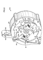
Figure 1 is an exploded perspective view of a self-retracting lifeline constructed according to the principles of the present invention; and -
Figure 2 is a top view of the self-retracting lifeline shown inFigure 1 with two plate members removed to show a centrifugal clutch assembly. - With reference to the drawings, a preferred embodiment self-retracting lifeline constructed according to the principles of the present invention is referenced by the
numeral 100. - As shown in
Figures 1 and2 , the preferred embodiment self-retractinglifeline 100 includes ahousing 101, which is preferably cylindrical in shape with acavity 144. Atab 102 extends outwardly from thehousing 101.Tab 102 includes anaperture 103 to enable the self-retractinglifeline 100 to be connected to a support structure (not shown) by a hook (not shown) or other suitable fasteners well known in the art. Within the cylindrical wall of thehousing 101, extending longitudinally therethrough, there are preferably fourbores 104. Thebores 104 are spaced approximately evenly around thehousing 101 and are configured and arranged to engagebolts 107. Aback plate member 105 is configured and arranged to cover one end of thehousing 101 and includesapertures 106, which are in alignment with thebores 104. Thebolts 107 connect theback plate member 105 to thehousing 101 byengaging apertures 106 and bores 104, respectively. Aspring assembly 108 fits within thecavity 144 of thehousing 101. Thespring assembly 108 includes aspiral motor spring 109 with an inner end (not shown) and an outer end (not shown). - A drum 111, which resembles a spool, includes a
cylinder portion 113 and arim 115 on each end of thecylinder portion 113. Abore 116 extends longitudinally through the center of thecylinder portion 113, and fourbores 117 extend longitudinally through thecylinder portion 113 about thebore 116. Thebores 117 form ribs 114 along thecylinder portion 113. Thebores 117 are preferably countersunk on one side (not shown) and are configured and arranged to engagebolts 110 withheads 110a. Theheads 110a fit within the countersunk portions of thebores 117 so as to not interfere with operation of the self-retractinglifeline 100. Therim 115 facing thehousing 101 includes a boss (not shown), which extends outward around thebore 116. The boss includes a slot (not shown) therein. The drum 111 is also configured and arranged to fit within thecavity 144 of thehousing 101. - A brake assembly includes a
brake hub 118 and acentrifugal clutch assembly 121. Thebrake hub 118 is generally ring-shaped to form acavity 120. Proximate the perimeter of thebrake hub 118 areapertures 119, which are in alignment withbores 104. Ratcheting catches orteeth 141 extend from thebrake hub 118 into thecavity 120. - The
centrifugal clutch assembly 121 includes aplate 143,pawls 128, andsprings 131. Theplate 143 is generally an oval-shaped disk including afinger portion 145 and ahook portion 146 at each end. Anaperture 122 proximate the center of theplate 143 is in alignment withbore 116, andapertures 125 are arranged aboutaperture 122 in alignment withbores 117. Theaperture 122 and theapertures 125 form a central, generally circular,portion 147 of theplate 143. Thefinger portions 145 and thehook portions 146 extend from thecentral portion 147 of theplate 143 to form the generally oval-shaped disk. Between thefinger portions 145 and thehook portions 146 are inletportions 124, which include expandedinlet portions 123. Thefinger portions 145 extend outward proximate one side of each end, and thehook portions 146 extend outward and then inward toward thefinger portions 145 proximate the opposite side of each end. Thefinger portions 145 extend outward to the end of theplate 143, but thehook portions 146 do not extend outward to the end of theplate 143. Thehook portions 146 extend outward approximately half the distance of thefinger portions 145 before they extend inward toward thefinger portions 145. Each end is basically a mirror image of the other end so thefinger portions 145 are diagonal from one another and thehook portions 146 are diagonal from one another. - The
inlet portions 124 and the expandedinlet portions 123 are notches in theplate 143 between thefinger portions 145 and thehook portions 146. Theinlet portions 124 are approximately 1/2 to 1/3 the width of theplate 143 and extend from proximate the middle of each end to proximate midway to theaperture 122. The expandedinlet portions 123 extend from the end of theinlet portions 124 proximate midway to theaperture 122 inward toward thehook portions 146. In other words, theinlet portions 124 and the expandedinlet portions 123 coordinate to define the shapes of thefinger portions 145 and thehook portions 146 and to form notches within which thesprings 131 and portions thepawls 128 are arranged. - The
pawls 128 each include abase portion 129, anintermediate portion 142, and anextension portion 130. Theintermediate portion 142 is generally circular in shape, and thebase portion 129 extends from one side and theextension portion 130 extends from another, generally opposite side of theintermediate portion 142. Thebase portion 129 is preferably curved to form an arc-shape. As shown inFigures 1 and2 , theintermediate portion 142 and thebase portion 129 resemble a mirror image of a comma. Theextension portion 130 is generally rectangular and extends generally 90° from thebase portion 129. - The
inlet portion 124 is configured and arranged to receive theintermediate portion 142, which may pivot therein. Theextension portion 130 extends into the expandedinlet portion 123, and thebase portion 129 extends outward from theinlet portion 124. The arc-shape of thebase portion 129 coordinates with thefinger portion 145 and thehook portion 146. The top of the arc-shape of thebase portion 129 follows the line of the curvature of the end of the finger portion 145 (and the end of the plate 143), and the bottom of the arc-shape follows the curvature of thehook portion 146. The top of the arc-shape is like an extension of thefinger portion 145, and the bottom of the arc-shape fits around thehook portion 146.Springs 131 are configured and arranged to fit within the expandedinlet portions 123 between thehook portions 146 and theextension portions 130. In a first position A, thespring 131 provides a constant force upon theextension portion 130 thereby pushing theextension portion 130 against thefinger portion 145 and thebase portion 129 against thehook portion 146. In a second position B, the force of thespring 130 is overcome by theextension portion 130 to compress thespring 130 thereby pivoting thepawl 128 so that theextension portion 130 moves toward thehook portion 146 and thebase portion 129 moves away from thehook portion 146. The first position A allows thepawl 130 to bypass the ratchetingteeth 141 of thebrake hub 118 while the second position B allows thepawl 130 to engage the ratchetingteeth 141 of thebrake hub 118. Positions A and B are shown inFigure 2 . - A
shaft 126 having alongitudinal bore 127 is configured and arranged to fit withinaperture 122, bore 116, and intocavity 144 proximate the inner end of thespiral motor spring 109. The inner end of thespiral motor spring 109 is inserted into the slot of the boss inrim 115 and is operatively connected thereto, keeping the inner end stationary. The boss is larger in diameter than theshaft 126 and is preferably as thick as thespiral motor spring 109. The outer end of thespiral motor spring 109 is operatively connected to the inner surface of thehousing 101 by means well known in the art. Thespiral motor spring 109 coils more or less tightly in response to rotation of the drum 111 as the webbing is unwound from and wound about the drum 111. Thespiral motor spring 109 maintains a continuous turning force on the drum 111 so that the webbing is continuously urged to be wound about the drum 111. - A
plate member 133, which is similarly configured and arranged asback plate member 105, covers the other end of thehousing 101 and includesapertures 135, which are in alignment with theapertures 119 and bores 104. Theplate member 133 also includes anaperture 134 in alignment withbore 127. Afront plate member 136 may also be used and includesnotches 138 in alignment withapertures 135 and an aperture 137 in alignment withaperture 134. Thefront plate member 136 may be a label.Bolts 139 operatively connect thefront plate member 136, theplate member 133, thebrake hub 118, and thehousing 101 by engaging thenotches 138, theapertures 135, theapertures 119, and thebores 104, respectively.Bolt 140 is inserted throughapertures 137 and 134 to engagebore 127. - A
rectangular webbing guide 132 includes anelongate aperture 132a configured and arranged to allow webbing (not shown) to extend from the drum 111 out of thehousing 101 through theaperture 132a. Raisedportions 148 extend from each side of thewebbing guide 132 and fit within anotch 149 in thehousing 101. Thewebbing guide 132 is then held in place between theback plate member 105 and theplate member 133. - The webbing (not shown) includes a first end, a second end, and an intermediate portion therebetween. Although the preferred embodiment utilizes webbing, it is recognized that cable, rope, or other suitable elongate member may be used. The webbing serves as the lifeline of the self-retracting
lifeline 100. The intermediate portion is wound onto and off of thecylinder portion 113 of the drum 111, and therims 115 on either side of thecylinder portion 113 keep the webbing on thecylinder portion 113. The first end of the webbing is fixedly operatively connected by means well known in the art to the drum 111. For example, one such way is shown and described inU.S. Patent 5, 186,289 , which is incorporated by reference herein. The second end of the webbing extends through thehousing 101 and is operatively connected to a fastening device (not shown) such as a snap hook. - In operation, the self-retracting
lifeline 100 is operatively connected to a support structure, and the webbing is operatively connected to a safety harness worn by a worker. The worker is free to move about the vicinity of the self-retractinglifeline 100, with only the length of the webbing restricting the distance of the worker's movement. As the worker moves further away from the self-retractinglifeline 100, webbing is paid out of the device as it is unwound from the drum 111. As the worker moves closer to the self-retractinglifeline 100, webbing is retracted into the device as it is wound about the drum 111. In the event a fall should occur, the sudden acceleration or high rate of speed at which the drum 111 turns to pay out webbing causes thepawls 128 to overcome the force of thesprings 131. The centrifugal force causes thepawls 128 to pivot away from thecentral portion 147 of theplate 143. Theintermediate portion 142 rotates within theinlet portion 124, causing theextension portion 130 to pivot and compress thespring 131 and thebase portion 129 to pivot away from theplate 143 and engage at least one of the ratchetingteeth 141 of thebrake hub 118. Engagement of thebrake hub 118 by thepawls 128 activates the rest of the brake assembly. Because thepawls 128 engage the ratchetingteeth 141 and can no longer rotate withincavity 120, thepawls 128 cause thebrake hub 118 to rotate. Thebrake hub 118, which is rotatably mounted toshaft 126 but does not normally rotate aboutshaft 126, begins to rotate with thepawls 128 and the drum 111. Oncepawls 128 have engaged ratchetingteeth 141, they cannot be disengaged until the drum 111 begins to rotate backward to rewind the webbing onto thecylinder portion 113. - One of the advantages of the present invention is the ease of manufacture and assembly of the self-retracting
lifeline 100. In prior art self-retracting lifelines, the pawls include pins about which the pawls pivot and the pawls are fixedly attached to the springs, which are fixedly attached to another component. The present invention does not include pins on the pawls or fixedly attach the springs to any component. Thepawls 128 and thesprings 131 must only be placed within the appropriate spaces formed by theplate 143. As the self-retracting lifeline is being assembled, thepawls 128 and thesprings 131 are simply dropped into place. - The
rim 115, theplate member 133, thebrake hub 118, and theplate 143 form an enclosure that defines boundaries of a confinement cavity, wherein thepawls 128 and thesprings 131 are held in place from movement in a first direction by a front stop (rim 115) and a back stop (plate member 133). Thepawls 128 are held in place from movement in a second direction generally perpendicular to the first direction by thebrake hub 118 and theplate 143 between thefinger portions 145 and thehook portions 146. The springs are held in place from movement in the second direction by thehook portions 146 of theplate 143 and theextension portions 130 of thepawls 128. Thepawls 128 and thesprings 131 are held in place by the boundaries of the confinement cavity. Therefore, thepawls 128 and thesprings 131 do not require any interconnections such as pins or other fixed attachments well known in the art. - It is recognized that the centrifugal
clutch assembly 121, including theplate 143, thepawls 128, and thesprings 131, of the present invention is not limited to use with the preferred embodiment self-retractinglifeline 100 and may be used with any other suitable self-retracting lifeline well known in the art. For example, another such self-retracting lifeline with which the present invention may be used isU.S. Patent 5,186,289 , which has been incorporated by reference herein. - The above specification, examples and data provide a complete description of the manufacture and use of the composition of the invention. Since many embodiments of the invention can be made without departing from the spirit and scope of the invention, the invention resides in the claims hereinafter appended.
Claims (3)
- A centrifugal clutch assembly for use with a self-retracting lifeline having a brake hub (118) with ratcheting teeth (141) within a cavity (120) of the brake hub (118) and a plate (143) with a first end and a second end, said first end and said second end each having a first portion (145) and a second portion (146) defining an inlet portion (124), comprising:a) a pawl (128) having a base portion (129), an intermediate portion (142), and an extension portion (130), said intermediate portion interconnecting said base portion and said extension portion; andb) a spring (131) placing a biasing force upon said pawl (128), wherein said pawl (128) is pivotable between a first position and a second position relative to the plate (143), said spring (131) pushing said pawl toward the plate (143) in the first position thereby bypassing the ratcheting teeth (141), said spring (131) being compressed thereby allowing said pawl to pivot away from the plate in the second position thereby engaging the ratcheting teeth (141); said centrifugal clutch assembly being characterised by:c) said intermediate portion (142) being configured and arranged to be placed within the inlet portion (124) between the first portion (145) and the second portion (146) on each end of the plate (143), the inlet portion providing a cavity within which said intermediate portion (142) of said pawl (128) is kept in place by the first portion and the second portion, said pawl (128) being pivotable within the cavity about the intermediate portion (142) and proximate the first portion (145) and the second portion (146), said base portion (129) extending outward from said intermediate portion (142) and away from said inlet portion (124), said extension portion (130) extending outward from said intermediate portion (142) and into said inlet portion (124); andd) the spring (131) being configured and arranged to be placed within the inlet portion (124) between the second portion (146) and said extension portion (130) of said pawl, the second portion and said extension portion keeping said spring in place within the inlet portion.
- The centrifugal clutch assembly of claim 1, further comprising an expanded inlet portion (123) extending from said inlet portion (124) proximate a central portion (147) of said plate (143) and toward said second portion (146) of said plate, said expanded inlet portion (123) being configured and arranged to receive said spring (131).
- A brake assembly comprising the centrifugal clutch assembly of claim 1 and an enclosure defining boundaries of a confinement cavity;
the pawl (128) and the spring (131) being contained within the boundaries of the confinement cavity by the enclosure absent interconnections, the enclosure keeping the pawl (128) and the spring (131) in place in a first direction and second direction, the first direction and the second direction being generally perpendicular to one another,
wherein the enclosure is formed by a rim (115), a plate member (133), a brake hub (118), and the plate (143), the pawl (128) and the spring (131) being kept in place in the first direction by the rim and the plate member, the pawl being kept in place in the second direction by the first and second portions (145, 146) of the plate (143), and the spring being kept in place in the second direction by the pawl and the plate.
Applications Claiming Priority (3)
| Application Number | Priority Date | Filing Date | Title |
|---|---|---|---|
| US50049103P | 2003-09-05 | 2003-09-05 | |
| US10/914,631 US7281620B2 (en) | 2003-09-05 | 2004-08-09 | Self-retracting lifeline |
| PCT/US2004/027243 WO2005025678A1 (en) | 2003-09-05 | 2004-08-23 | Self-retracting lifeline |
Publications (2)
| Publication Number | Publication Date |
|---|---|
| EP1663405A1 EP1663405A1 (en) | 2006-06-07 |
| EP1663405B1 true EP1663405B1 (en) | 2015-06-10 |
Family
ID=34228714
Family Applications (1)
| Application Number | Title | Priority Date | Filing Date |
|---|---|---|---|
| EP04781848.9A Expired - Lifetime EP1663405B1 (en) | 2003-09-05 | 2004-08-23 | Self-retracting lifeline |
Country Status (8)
| Country | Link |
|---|---|
| US (1) | US7281620B2 (en) |
| EP (1) | EP1663405B1 (en) |
| KR (1) | KR20060064684A (en) |
| AU (1) | AU2004271950B2 (en) |
| CA (1) | CA2535847C (en) |
| DK (1) | DK1663405T3 (en) |
| ES (1) | ES2540559T3 (en) |
| WO (1) | WO2005025678A1 (en) |
Cited By (1)
| Publication number | Priority date | Publication date | Assignee | Title |
|---|---|---|---|---|
| US20220305308A1 (en) * | 2021-03-26 | 2022-09-29 | Msa Technology, Llc | Two-Part Locking Polymer Hub for Cable Self-Retracting Device |
Families Citing this family (72)
| Publication number | Priority date | Publication date | Assignee | Title |
|---|---|---|---|---|
| US20080314685A1 (en) * | 2005-12-14 | 2008-12-25 | Verstegen Eugene Gijsbertus Ma | Devices and Methods For Safely Evacuating an Individual During an Emergency From a Tall Structure |
| US7946387B2 (en) * | 2006-01-03 | 2011-05-24 | D B Industries, Inc. | Self-retracting lifeline |
| US7870934B2 (en) | 2006-03-14 | 2011-01-18 | Mine Safety Appliances Company | Self-retracting lanyard and braking mechanism with pawl lockout |
| WO2008008225A2 (en) * | 2006-07-10 | 2008-01-17 | Sigma Industries, Llc | Retractable lifeline safety device |
| US20080041661A1 (en) | 2006-08-08 | 2008-02-21 | D B Industries, Inc. | Retractable horizontal lifeline assembly |
| US20080035423A1 (en) * | 2006-08-08 | 2008-02-14 | D B Industries, Inc. | Retractable horizontal lifeline assembly |
| GB2449134B (en) * | 2007-08-13 | 2009-08-12 | Checkmate Safety Llp | Fall arrest block |
| US20090078505A1 (en) * | 2007-09-20 | 2009-03-26 | D B Industries, Inc. | Safety device |
| US7780146B2 (en) * | 2007-09-28 | 2010-08-24 | D B Industries, Inc. | Retrieval assembly |
| BRPI0722115A2 (en) * | 2007-10-12 | 2015-10-13 | Latchways Plc | rotational energy absorber, safety device and fall arrest system |
| US8701833B2 (en) * | 2008-04-22 | 2014-04-22 | Gf Protection Inc. | Distance limiting self-retractable lifeline |
| AU2010205907B2 (en) * | 2009-01-19 | 2013-11-14 | Roofsafe-T-Systems Pty Limited | Self-retracting lifeline |
| GB2467953B (en) * | 2009-02-20 | 2013-07-17 | Latchways Plc | Fall arrest system safety device |
| US10688323B2 (en) * | 2009-03-09 | 2020-06-23 | D B Industries, Llc | Safety device with fall arrest and descending modes |
| US9764172B2 (en) * | 2009-03-09 | 2017-09-19 | D B Industries, Llc | Safety device with fall arrest and descending modes |
| NZ575464A (en) * | 2009-03-10 | 2010-07-30 | Holmes Solutions Ltd | Improvements in and relating to braking mechanisms |
| US8567562B2 (en) * | 2009-11-02 | 2013-10-29 | B D Industries, LLC | Brake assembly for a self-retracting lifeline assembly |
| DK2512966T3 (en) * | 2009-12-17 | 2018-05-22 | Reel Tech Pty Ltd | CONTROL OF HOSE WIND WELDING SPEED |
| USD656686S1 (en) | 2010-03-17 | 2012-03-27 | LynRus Aluminum Products, LLC | Auto-arresting safety device |
| US9199103B2 (en) | 2010-05-12 | 2015-12-01 | Msa Technology, Llc | Fall protection arrangement |
| US8430207B2 (en) | 2010-06-23 | 2013-04-30 | 3M Innovative Properties Company | Preassembled and pretorqued friction brake and method of making a safety device containing such a friction brake |
| US8256574B2 (en) | 2010-06-23 | 2012-09-04 | 3M Innovative Properties Company | Centrifugally-operated apparatus |
| US8430206B2 (en) | 2010-06-23 | 2013-04-30 | 3M Innovative Properties Company | Safety devices comprising a load-bearing composite polymeric housing and a load-bearing anchorage plate |
| WO2012068420A2 (en) * | 2010-11-17 | 2012-05-24 | Reliance Industries, Llc | Retractable fall arrester with component assembly and cantilevered main shaft |
| GB201118597D0 (en) * | 2011-10-27 | 2011-12-07 | Latchways Plc | Fall arrest system safety device |
| US9121462B2 (en) * | 2011-10-28 | 2015-09-01 | D B Industries, Llc | Self-retracting lifeline |
| SG2012086005A (en) * | 2012-11-22 | 2014-06-27 | Cal Comp Prec Singapore Ltd | Gear assembly and electronic device using the same |
| US10004927B2 (en) | 2012-12-02 | 2018-06-26 | Reliance Industries, Llc | Retractable lanyard lock mechanism |
| US9821178B2 (en) | 2013-02-08 | 2017-11-21 | D B Industries, Llc | Bracket assembly |
| GB201303153D0 (en) * | 2013-02-22 | 2013-04-10 | Capital Safety Group Northern Europ Ltd | Fall Arrest Device |
| JP5860001B2 (en) * | 2013-04-18 | 2016-02-16 | 藤井電工株式会社 | Lanyard and safety belt with the lanyard |
| NL2011756C2 (en) | 2013-08-05 | 2015-02-09 | Evacuator Internat Property B V | Device for evacuating individuals. |
| US20150307197A1 (en) * | 2014-04-28 | 2015-10-29 | Capewell Systems Llc | Multi-Use Emergency Descent Device |
| MX364898B (en) | 2014-08-18 | 2019-05-13 | Eddy Current Lp | Latching devices. |
| EP3183803B1 (en) | 2014-08-18 | 2021-04-14 | Eddy Current Limited Partnership | Tuning of a kinematic relationship between members |
| CA2957635A1 (en) | 2014-08-18 | 2016-02-25 | Eddy Current Limited Partnership | Tuning of a kinematic relationship between members |
| WO2016029059A2 (en) | 2014-08-20 | 2016-02-25 | Mcgowan John Lewis | Eddy current braking device for linear systems |
| US10556138B2 (en) * | 2014-10-02 | 2020-02-11 | Honeywell International Inc. | Sealed self-retracting lifeline |
| MX391252B (en) | 2014-12-04 | 2025-03-12 | Eddy Current Lp | ENERGY ABSORPTION DEVICE. |
| EP3227990B1 (en) | 2014-12-04 | 2023-10-11 | Eddy Current Limited Partnership | Eddy current brake configurations |
| JP6699906B2 (en) | 2014-12-04 | 2020-05-27 | エディ・カーレント・リミテッド・パートナーシップ | Transmission mechanism incorporating eddy current damping and method of transmitting eddy current drag |
| CN106999736B (en) | 2014-12-04 | 2021-06-08 | 涡流有限合伙公司 | How to Change Eddy Current Interactions |
| JP2018505634A (en) | 2014-12-04 | 2018-02-22 | エディ・カーレント・リミテッド・パートナーシップ | Latch activation between elements |
| TWI542799B (en) * | 2014-12-19 | 2016-07-21 | 台達電子工業股份有限公司 | Motor braking device |
| GB2535142B (en) * | 2015-01-28 | 2020-07-29 | Latchways Plc | Energy absorber and fall arrest system safety device |
| US20160236018A1 (en) * | 2015-02-15 | 2016-08-18 | Aerohook Technology Co., Ltd. | Easy to Assemble Anti-dropping Device |
| CN107614063A (en) * | 2015-06-03 | 2018-01-19 | 信实工业有限责任公司 | Sealed retractable fall capture stop |
| GB2539418B (en) * | 2015-06-15 | 2019-10-02 | Swisslogo Ag | Self-braking pulley |
| FR3042719B1 (en) * | 2015-10-26 | 2017-12-01 | Vertic | AUTOMATICALLY RECALLING ANTI-FALLING DEVICE AND METHOD OF OPERATION THEREOF |
| CN118566534A (en) | 2015-12-18 | 2024-08-30 | 涡流有限合伙公司 | Variable behavior control mechanism for power system |
| GB2556892B (en) * | 2016-11-23 | 2022-04-27 | Latchways Plc | Self-retracting lifeline fall arrest device |
| US10143867B2 (en) * | 2016-11-29 | 2018-12-04 | Aerohook Technology Co., Ltd. | Dual-suspensible anti-falling device |
| CN106865364B (en) * | 2017-02-23 | 2018-07-31 | 胡连湖 | Automatic hose reel |
| CN110869089A (en) | 2017-07-13 | 2020-03-06 | 3M创新有限公司 | Fall protection equipment including friction brakes |
| US20190338593A1 (en) * | 2017-07-17 | 2019-11-07 | Safeworks, Llc | Integrated climb assist and fall arrest systems and methods |
| US11633634B2 (en) * | 2018-04-06 | 2023-04-25 | Msa Technology, Llc | Cut-resistant leading edge fall arrest system and method |
| US11992712B2 (en) * | 2018-04-19 | 2024-05-28 | Honeywell International Inc. | Polarized deceleration brake for self retracting device |
| TWI673082B (en) * | 2018-09-11 | 2019-10-01 | 振鋒企業股份有限公司 | Fall arrester and its lifesaving seat |
| CN212090567U (en) | 2019-09-20 | 2020-12-08 | 中际联合(北京)科技股份有限公司 | Linkage operation assembly, anti-falling device and anti-falling system |
| EP4031254B1 (en) | 2019-09-20 | 2025-07-09 | Trublue LLC | Lock-off descent control systems and devices |
| CN110652665A (en) * | 2019-09-25 | 2020-01-07 | 苏州斯久德安全防护科技有限公司 | Speed difference automatic controller |
| CN110885008B (en) * | 2019-11-14 | 2022-06-10 | 金华捷科工具有限公司 | A buffer type speed difference fall arrester |
| EP4121176B1 (en) | 2020-03-18 | 2025-03-12 | Trublue LLC | Line dispensing devices |
| US11534634B2 (en) * | 2020-04-03 | 2022-12-27 | Honeywell International Inc. | Brake assembly for fall arrest system |
| WO2022003500A1 (en) * | 2020-07-02 | 2022-01-06 | 3M Innovative Properties Company | Fall-protection apparatus comprising dual-actuatable braking device |
| WO2022009174A1 (en) * | 2020-07-10 | 2022-01-13 | 3M Innovative Properties Company | Fall-protection apparatus with braking device comprising flexure-borne pawl |
| WO2022009175A1 (en) * | 2020-07-10 | 2022-01-13 | 3M Innovative Properties Company | Fall-protection apparatus with braking device comprising flexure-borne pawl and drum-mounted buttress |
| US11993477B2 (en) * | 2020-08-18 | 2024-05-28 | Checkmate Lifting & Safety Ltd | Retractable tool lanyard |
| US11226016B1 (en) * | 2020-11-11 | 2022-01-18 | Driven Innovations Ltd. | Automatic free-coasting freewheel apparatus |
| US20220249888A1 (en) * | 2021-02-11 | 2022-08-11 | The Boeing Company | Multiple Self-Retracting Lanyard, Single Brake Fall Protection Systems and Methods |
| TWI762326B (en) * | 2021-05-21 | 2022-04-21 | 貝加工業有限公司 | Drum brake arrester |
| CN119018723A (en) * | 2023-05-23 | 2024-11-26 | 厦门松霖科技股份有限公司 | A hose storage device with adjustable pulling force |
Citations (4)
| Publication number | Priority date | Publication date | Assignee | Title |
|---|---|---|---|---|
| US2268243A (en) * | 1940-08-02 | 1941-12-30 | Sullivan Machinery Co | Ratchet and pawl mechanism |
| US3879016A (en) * | 1973-09-07 | 1975-04-22 | Sisarakenneteollisuus Oy Sirat | Safety device |
| US4177962A (en) * | 1977-05-20 | 1979-12-11 | Eckhard Hildebrandt | Winding-in device for vehicle safety belts |
| US6523771B2 (en) * | 2000-07-11 | 2003-02-25 | Kabushiki Kaisha Tokai-Rika-Denki Seisakusho | Webbing retractor |
Family Cites Families (10)
| Publication number | Priority date | Publication date | Assignee | Title |
|---|---|---|---|---|
| GB238302A (en) | 1924-05-16 | 1925-08-17 | John Leonard Holman | Improvements in or relating to pawl-driven mechanism |
| US4589523A (en) | 1984-02-10 | 1986-05-20 | Rose Manufacturing Company | Fall arrester and emergency retrieval apparatus and anchor apparatus therefor |
| GB2192679B (en) | 1986-05-28 | 1989-12-13 | Barrow Hepburn Equip Ltd | Fall-arrest apparatus |
| US4877110A (en) | 1988-10-14 | 1989-10-31 | D B Industries, Inc. | Safety device with retractable lifeline |
| US5070978A (en) | 1990-04-19 | 1991-12-10 | Pires Paul B | One way drive device |
| US5186289A (en) | 1990-10-26 | 1993-02-16 | D B Industries, Inc. | Retractable lifeline safety device |
| GB9023703D0 (en) | 1990-10-31 | 1990-12-12 | Barrow Hepburn Sala Ltd | Fall-arrest apparatus |
| US5722612A (en) * | 1994-01-18 | 1998-03-03 | Barrow Hepburn Sala Ltd. | Clutch mechanism for use in safety apparatus |
| DE29515703U1 (en) | 1995-10-02 | 1996-02-08 | Föhl, Artur, 73614 Schorndorf | Rotary drive device for a belt tensioner |
| DE19758495C2 (en) | 1997-08-12 | 2003-12-04 | Hs Tech & Design | seatbelt |
-
2004
- 2004-08-09 US US10/914,631 patent/US7281620B2/en not_active Expired - Lifetime
- 2004-08-23 CA CA002535847A patent/CA2535847C/en not_active Expired - Lifetime
- 2004-08-23 WO PCT/US2004/027243 patent/WO2005025678A1/en not_active Ceased
- 2004-08-23 KR KR1020067006450A patent/KR20060064684A/en not_active Withdrawn
- 2004-08-23 AU AU2004271950A patent/AU2004271950B2/en not_active Expired
- 2004-08-23 ES ES04781848.9T patent/ES2540559T3/en not_active Expired - Lifetime
- 2004-08-23 EP EP04781848.9A patent/EP1663405B1/en not_active Expired - Lifetime
- 2004-08-23 DK DK04781848.9T patent/DK1663405T3/en active
Patent Citations (4)
| Publication number | Priority date | Publication date | Assignee | Title |
|---|---|---|---|---|
| US2268243A (en) * | 1940-08-02 | 1941-12-30 | Sullivan Machinery Co | Ratchet and pawl mechanism |
| US3879016A (en) * | 1973-09-07 | 1975-04-22 | Sisarakenneteollisuus Oy Sirat | Safety device |
| US4177962A (en) * | 1977-05-20 | 1979-12-11 | Eckhard Hildebrandt | Winding-in device for vehicle safety belts |
| US6523771B2 (en) * | 2000-07-11 | 2003-02-25 | Kabushiki Kaisha Tokai-Rika-Denki Seisakusho | Webbing retractor |
Cited By (1)
| Publication number | Priority date | Publication date | Assignee | Title |
|---|---|---|---|---|
| US20220305308A1 (en) * | 2021-03-26 | 2022-09-29 | Msa Technology, Llc | Two-Part Locking Polymer Hub for Cable Self-Retracting Device |
Also Published As
| Publication number | Publication date |
|---|---|
| EP1663405A1 (en) | 2006-06-07 |
| AU2004271950A1 (en) | 2005-03-24 |
| AU2004271950B2 (en) | 2010-07-08 |
| DK1663405T3 (en) | 2015-06-29 |
| US7281620B2 (en) | 2007-10-16 |
| CA2535847A1 (en) | 2005-03-24 |
| US20050051659A1 (en) | 2005-03-10 |
| WO2005025678A1 (en) | 2005-03-24 |
| KR20060064684A (en) | 2006-06-13 |
| CA2535847C (en) | 2009-10-20 |
| ES2540559T3 (en) | 2015-07-10 |
Similar Documents
| Publication | Publication Date | Title |
|---|---|---|
| EP1663405B1 (en) | Self-retracting lifeline | |
| EP1968713B1 (en) | Self-retracting lifeline | |
| US12005276B2 (en) | Centrifugal brake assembly | |
| US8567562B2 (en) | Brake assembly for a self-retracting lifeline assembly | |
| US9764172B2 (en) | Safety device with fall arrest and descending modes | |
| US8181744B2 (en) | Self-retracting lifeline systems and braking systems therefor | |
| MXPA06003650A (en) | Self-retracting lifeline |
Legal Events
| Date | Code | Title | Description |
|---|---|---|---|
| PUAI | Public reference made under article 153(3) epc to a published international application that has entered the european phase |
Free format text: ORIGINAL CODE: 0009012 |
|
| 17P | Request for examination filed |
Effective date: 20060222 |
|
| AK | Designated contracting states |
Kind code of ref document: A1 Designated state(s): AT BE BG CH CY CZ DE DK EE ES FI FR GB GR HU IE IT LI LU MC NL PL PT RO SE SI SK TR |
|
| DAX | Request for extension of the european patent (deleted) | ||
| 17Q | First examination report despatched |
Effective date: 20100308 |
|
| RAP1 | Party data changed (applicant data changed or rights of an application transferred) |
Owner name: D B INDUSTRIES, LLC |
|
| REG | Reference to a national code |
Ref country code: DE Ref legal event code: R079 Ref document number: 602004047339 Country of ref document: DE Free format text: PREVIOUS MAIN CLASS: A62B0035040000 Ipc: A62B0035000000 |
|
| GRAP | Despatch of communication of intention to grant a patent |
Free format text: ORIGINAL CODE: EPIDOSNIGR1 |
|
| RIC1 | Information provided on ipc code assigned before grant |
Ipc: F16D 41/12 20060101ALI20150212BHEP Ipc: A62B 35/00 20060101AFI20150212BHEP Ipc: F16D 43/16 20060101ALI20150212BHEP Ipc: F16D 63/00 20060101ALI20150212BHEP Ipc: A62B 1/10 20060101ALI20150212BHEP |
|
| INTG | Intention to grant announced |
Effective date: 20150317 |
|
| GRAS | Grant fee paid |
Free format text: ORIGINAL CODE: EPIDOSNIGR3 |
|
| GRAA | (expected) grant |
Free format text: ORIGINAL CODE: 0009210 |
|
| AK | Designated contracting states |
Kind code of ref document: B1 Designated state(s): AT BE BG CH CY CZ DE DK EE ES FI FR GB GR HU IE IT LI LU MC NL PL PT RO SE SI SK TR |
|
| REG | Reference to a national code |
Ref country code: GB Ref legal event code: FG4D |
|
| REG | Reference to a national code |
Ref country code: CH Ref legal event code: EP |
|
| REG | Reference to a national code |
Ref country code: DK Ref legal event code: T3 Effective date: 20150625 |
|
| REG | Reference to a national code |
Ref country code: SE Ref legal event code: TRGR |
|
| REG | Reference to a national code |
Ref country code: NL Ref legal event code: T3 |
|
| REG | Reference to a national code |
Ref country code: ES Ref legal event code: FG2A Ref document number: 2540559 Country of ref document: ES Kind code of ref document: T3 Effective date: 20150710 |
|
| REG | Reference to a national code |
Ref country code: AT Ref legal event code: REF Ref document number: 730646 Country of ref document: AT Kind code of ref document: T Effective date: 20150715 |
|
| REG | Reference to a national code |
Ref country code: DE Ref legal event code: R096 Ref document number: 602004047339 Country of ref document: DE |
|
| REG | Reference to a national code |
Ref country code: IE Ref legal event code: FG4D |
|
| PG25 | Lapsed in a contracting state [announced via postgrant information from national office to epo] |
Ref country code: FI Free format text: LAPSE BECAUSE OF FAILURE TO SUBMIT A TRANSLATION OF THE DESCRIPTION OR TO PAY THE FEE WITHIN THE PRESCRIBED TIME-LIMIT Effective date: 20150610 |
|
| REG | Reference to a national code |
Ref country code: AT Ref legal event code: MK05 Ref document number: 730646 Country of ref document: AT Kind code of ref document: T Effective date: 20150610 |
|
| PG25 | Lapsed in a contracting state [announced via postgrant information from national office to epo] |
Ref country code: GR Free format text: LAPSE BECAUSE OF FAILURE TO SUBMIT A TRANSLATION OF THE DESCRIPTION OR TO PAY THE FEE WITHIN THE PRESCRIBED TIME-LIMIT Effective date: 20150911 Ref country code: BG Free format text: LAPSE BECAUSE OF FAILURE TO SUBMIT A TRANSLATION OF THE DESCRIPTION OR TO PAY THE FEE WITHIN THE PRESCRIBED TIME-LIMIT Effective date: 20150910 |
|
| PG25 | Lapsed in a contracting state [announced via postgrant information from national office to epo] |
Ref country code: EE Free format text: LAPSE BECAUSE OF FAILURE TO SUBMIT A TRANSLATION OF THE DESCRIPTION OR TO PAY THE FEE WITHIN THE PRESCRIBED TIME-LIMIT Effective date: 20150610 |
|
| PG25 | Lapsed in a contracting state [announced via postgrant information from national office to epo] |
Ref country code: RO Free format text: LAPSE BECAUSE OF NON-PAYMENT OF DUE FEES Effective date: 20150610 Ref country code: PT Free format text: LAPSE BECAUSE OF FAILURE TO SUBMIT A TRANSLATION OF THE DESCRIPTION OR TO PAY THE FEE WITHIN THE PRESCRIBED TIME-LIMIT Effective date: 20151012 Ref country code: PL Free format text: LAPSE BECAUSE OF FAILURE TO SUBMIT A TRANSLATION OF THE DESCRIPTION OR TO PAY THE FEE WITHIN THE PRESCRIBED TIME-LIMIT Effective date: 20150610 Ref country code: CZ Free format text: LAPSE BECAUSE OF FAILURE TO SUBMIT A TRANSLATION OF THE DESCRIPTION OR TO PAY THE FEE WITHIN THE PRESCRIBED TIME-LIMIT Effective date: 20150610 Ref country code: SK Free format text: LAPSE BECAUSE OF FAILURE TO SUBMIT A TRANSLATION OF THE DESCRIPTION OR TO PAY THE FEE WITHIN THE PRESCRIBED TIME-LIMIT Effective date: 20150610 Ref country code: AT Free format text: LAPSE BECAUSE OF FAILURE TO SUBMIT A TRANSLATION OF THE DESCRIPTION OR TO PAY THE FEE WITHIN THE PRESCRIBED TIME-LIMIT Effective date: 20150610 |
|
| REG | Reference to a national code |
Ref country code: DE Ref legal event code: R097 Ref document number: 602004047339 Country of ref document: DE |
|
| PG25 | Lapsed in a contracting state [announced via postgrant information from national office to epo] |
Ref country code: MC Free format text: LAPSE BECAUSE OF FAILURE TO SUBMIT A TRANSLATION OF THE DESCRIPTION OR TO PAY THE FEE WITHIN THE PRESCRIBED TIME-LIMIT Effective date: 20150610 Ref country code: LU Free format text: LAPSE BECAUSE OF FAILURE TO SUBMIT A TRANSLATION OF THE DESCRIPTION OR TO PAY THE FEE WITHIN THE PRESCRIBED TIME-LIMIT Effective date: 20150823 |
|
| REG | Reference to a national code |
Ref country code: CH Ref legal event code: PL |
|
| PLBE | No opposition filed within time limit |
Free format text: ORIGINAL CODE: 0009261 |
|
| STAA | Information on the status of an ep patent application or granted ep patent |
Free format text: STATUS: NO OPPOSITION FILED WITHIN TIME LIMIT |
|
| PG25 | Lapsed in a contracting state [announced via postgrant information from national office to epo] |
Ref country code: CH Free format text: LAPSE BECAUSE OF NON-PAYMENT OF DUE FEES Effective date: 20150831 Ref country code: IT Free format text: LAPSE BECAUSE OF FAILURE TO SUBMIT A TRANSLATION OF THE DESCRIPTION OR TO PAY THE FEE WITHIN THE PRESCRIBED TIME-LIMIT Effective date: 20150610 Ref country code: LI Free format text: LAPSE BECAUSE OF NON-PAYMENT OF DUE FEES Effective date: 20150831 |
|
| 26N | No opposition filed |
Effective date: 20160311 |
|
| REG | Reference to a national code |
Ref country code: DE Ref legal event code: R082 Ref document number: 602004047339 Country of ref document: DE Representative=s name: HERNANDEZ, YORCK, DIPL.-ING., DE |
|
| PG25 | Lapsed in a contracting state [announced via postgrant information from national office to epo] |
Ref country code: SI Free format text: LAPSE BECAUSE OF FAILURE TO SUBMIT A TRANSLATION OF THE DESCRIPTION OR TO PAY THE FEE WITHIN THE PRESCRIBED TIME-LIMIT Effective date: 20150610 |
|
| REG | Reference to a national code |
Ref country code: IE Ref legal event code: MM4A |
|
| REG | Reference to a national code |
Ref country code: FR Ref legal event code: PLFP Year of fee payment: 13 |
|
| PG25 | Lapsed in a contracting state [announced via postgrant information from national office to epo] |
Ref country code: IE Free format text: LAPSE BECAUSE OF NON-PAYMENT OF DUE FEES Effective date: 20150823 |
|
| PG25 | Lapsed in a contracting state [announced via postgrant information from national office to epo] |
Ref country code: BE Free format text: LAPSE BECAUSE OF FAILURE TO SUBMIT A TRANSLATION OF THE DESCRIPTION OR TO PAY THE FEE WITHIN THE PRESCRIBED TIME-LIMIT Effective date: 20150610 |
|
| PG25 | Lapsed in a contracting state [announced via postgrant information from national office to epo] |
Ref country code: HU Free format text: LAPSE BECAUSE OF FAILURE TO SUBMIT A TRANSLATION OF THE DESCRIPTION OR TO PAY THE FEE WITHIN THE PRESCRIBED TIME-LIMIT; INVALID AB INITIO Effective date: 20040823 |
|
| PG25 | Lapsed in a contracting state [announced via postgrant information from national office to epo] |
Ref country code: CY Free format text: LAPSE BECAUSE OF FAILURE TO SUBMIT A TRANSLATION OF THE DESCRIPTION OR TO PAY THE FEE WITHIN THE PRESCRIBED TIME-LIMIT Effective date: 20150610 |
|
| REG | Reference to a national code |
Ref country code: FR Ref legal event code: PLFP Year of fee payment: 14 |
|
| PG25 | Lapsed in a contracting state [announced via postgrant information from national office to epo] |
Ref country code: TR Free format text: LAPSE BECAUSE OF FAILURE TO SUBMIT A TRANSLATION OF THE DESCRIPTION OR TO PAY THE FEE WITHIN THE PRESCRIBED TIME-LIMIT Effective date: 20150610 |
|
| PGFP | Annual fee paid to national office [announced via postgrant information from national office to epo] |
Ref country code: NL Payment date: 20170814 Year of fee payment: 14 |
|
| REG | Reference to a national code |
Ref country code: FR Ref legal event code: PLFP Year of fee payment: 15 |
|
| REG | Reference to a national code |
Ref country code: NL Ref legal event code: MM Effective date: 20180901 |
|
| PG25 | Lapsed in a contracting state [announced via postgrant information from national office to epo] |
Ref country code: NL Free format text: LAPSE BECAUSE OF NON-PAYMENT OF DUE FEES Effective date: 20180901 |
|
| PGFP | Annual fee paid to national office [announced via postgrant information from national office to epo] |
Ref country code: ES Payment date: 20200901 Year of fee payment: 17 Ref country code: DK Payment date: 20200811 Year of fee payment: 17 |
|
| PGFP | Annual fee paid to national office [announced via postgrant information from national office to epo] |
Ref country code: SE Payment date: 20200811 Year of fee payment: 17 |
|
| REG | Reference to a national code |
Ref country code: DK Ref legal event code: EBP Effective date: 20210831 |
|
| REG | Reference to a national code |
Ref country code: SE Ref legal event code: EUG |
|
| PG25 | Lapsed in a contracting state [announced via postgrant information from national office to epo] |
Ref country code: SE Free format text: LAPSE BECAUSE OF NON-PAYMENT OF DUE FEES Effective date: 20210824 |
|
| PG25 | Lapsed in a contracting state [announced via postgrant information from national office to epo] |
Ref country code: DK Free format text: LAPSE BECAUSE OF NON-PAYMENT OF DUE FEES Effective date: 20210831 |
|
| REG | Reference to a national code |
Ref country code: ES Ref legal event code: FD2A Effective date: 20220929 |
|
| PG25 | Lapsed in a contracting state [announced via postgrant information from national office to epo] |
Ref country code: ES Free format text: LAPSE BECAUSE OF NON-PAYMENT OF DUE FEES Effective date: 20210824 |
|
| P01 | Opt-out of the competence of the unified patent court (upc) registered |
Effective date: 20230530 |
|
| PGFP | Annual fee paid to national office [announced via postgrant information from national office to epo] |
Ref country code: GB Payment date: 20230720 Year of fee payment: 20 |
|
| PGFP | Annual fee paid to national office [announced via postgrant information from national office to epo] |
Ref country code: FR Payment date: 20230720 Year of fee payment: 20 Ref country code: DE Payment date: 20230720 Year of fee payment: 20 |
|
| REG | Reference to a national code |
Ref country code: DE Ref legal event code: R071 Ref document number: 602004047339 Country of ref document: DE |
|
| REG | Reference to a national code |
Ref country code: GB Ref legal event code: PE20 Expiry date: 20240822 |
|
| PG25 | Lapsed in a contracting state [announced via postgrant information from national office to epo] |
Ref country code: GB Free format text: LAPSE BECAUSE OF EXPIRATION OF PROTECTION Effective date: 20240822 |
|
| PG25 | Lapsed in a contracting state [announced via postgrant information from national office to epo] |
Ref country code: GB Free format text: LAPSE BECAUSE OF EXPIRATION OF PROTECTION Effective date: 20240822 |