EP1663367B1 - Peep valve - Google Patents
Peep valve Download PDFInfo
- Publication number
- EP1663367B1 EP1663367B1 EP04768345A EP04768345A EP1663367B1 EP 1663367 B1 EP1663367 B1 EP 1663367B1 EP 04768345 A EP04768345 A EP 04768345A EP 04768345 A EP04768345 A EP 04768345A EP 1663367 B1 EP1663367 B1 EP 1663367B1
- Authority
- EP
- European Patent Office
- Prior art keywords
- valve
- sealing disc
- closure
- peep
- peep valve
- Prior art date
- Legal status (The legal status is an assumption and is not a legal conclusion. Google has not performed a legal analysis and makes no representation as to the accuracy of the status listed.)
- Expired - Lifetime
Links
- 244000144985 peep Species 0.000 title claims abstract 25
- 238000007789 sealing Methods 0.000 claims abstract description 99
- 239000000463 material Substances 0.000 claims abstract description 22
- 230000000241 respiratory effect Effects 0.000 claims abstract description 16
- 230000015572 biosynthetic process Effects 0.000 claims description 11
- 238000004891 communication Methods 0.000 claims description 2
- 239000013536 elastomeric material Substances 0.000 claims description 2
- 239000012530 fluid Substances 0.000 claims description 2
- 239000007789 gas Substances 0.000 description 4
- 229920002379 silicone rubber Polymers 0.000 description 4
- 239000004945 silicone rubber Substances 0.000 description 4
- 239000004033 plastic Substances 0.000 description 3
- 229920003023 plastic Polymers 0.000 description 3
- 238000001746 injection moulding Methods 0.000 description 2
- 210000004072 lung Anatomy 0.000 description 2
- 230000002265 prevention Effects 0.000 description 2
- 230000029058 respiratory gaseous exchange Effects 0.000 description 2
- MYMOFIZGZYHOMD-UHFFFAOYSA-N Dioxygen Chemical compound O=O MYMOFIZGZYHOMD-UHFFFAOYSA-N 0.000 description 1
- 230000002457 bidirectional effect Effects 0.000 description 1
- 238000010276 construction Methods 0.000 description 1
- 238000000034 method Methods 0.000 description 1
- 239000000203 mixture Substances 0.000 description 1
- 239000001301 oxygen Substances 0.000 description 1
- 229910052760 oxygen Inorganic materials 0.000 description 1
- 230000002093 peripheral effect Effects 0.000 description 1
- 238000013022 venting Methods 0.000 description 1
Images


Classifications
-
- A—HUMAN NECESSITIES
- A61—MEDICAL OR VETERINARY SCIENCE; HYGIENE
- A61M—DEVICES FOR INTRODUCING MEDIA INTO, OR ONTO, THE BODY; DEVICES FOR TRANSDUCING BODY MEDIA OR FOR TAKING MEDIA FROM THE BODY; DEVICES FOR PRODUCING OR ENDING SLEEP OR STUPOR
- A61M16/00—Devices for influencing the respiratory system of patients by gas treatment, e.g. ventilators; Tracheal tubes
- A61M16/20—Valves specially adapted to medical respiratory devices
- A61M16/208—Non-controlled one-way valves, e.g. exhalation, check, pop-off non-rebreathing valves
-
- A—HUMAN NECESSITIES
- A61—MEDICAL OR VETERINARY SCIENCE; HYGIENE
- A61M—DEVICES FOR INTRODUCING MEDIA INTO, OR ONTO, THE BODY; DEVICES FOR TRANSDUCING BODY MEDIA OR FOR TAKING MEDIA FROM THE BODY; DEVICES FOR PRODUCING OR ENDING SLEEP OR STUPOR
- A61M16/00—Devices for influencing the respiratory system of patients by gas treatment, e.g. ventilators; Tracheal tubes
- A61M16/20—Valves specially adapted to medical respiratory devices
- A61M16/201—Controlled valves
- A61M16/206—Capsule valves, e.g. mushroom, membrane valves
Definitions
- This invention relates to valves that apply Positive End Expiratory Pressure (PEEP) to an artificial respiratory circuit, ie so-called PEEP valves, and in particular to PEEP valves that allow bi-directional flow.
- PEEP Positive End Expiratory Pressure
- the patient When a patient is unable to breathe unaided, or requires assistance with breathing, the patient is usually connected to an artificial respiratory circuit including a ventilator programmed by a clinician to deliver an appropriate volume of air, or an air/oxygen mixture, to the patient.
- an artificial respiratory circuit including a ventilator programmed by a clinician to deliver an appropriate volume of air, or an air/oxygen mixture, to the patient.
- a respiratory circuit where the patient is breathing spontaneously but requiring pressure support, it is desirable to prevent the patient from exhaling fully, and therefore the patient's lungs from deflating fully. This is because complete deflation, and subsequent reflation, of the patient's lungs requires a significant amount of the patient's energy.
- Prevention of total exhalation is generally achieved by including a mechanism in the respiratory circuit which only allows exhaled breath above an appropriate exhalation pressure to escape the respiratory circuit. Prevention of total exhalation in this way is known as applying "PEEP” to the respiratory circuit, where "PEEP” refers to Positive End Expiratory Pressure.
- PEEP Positive End Expiratory Pressure
- a widely used method of applying PEEP to a respiratory circuit is by using a so-called PEEP valve to provide a fixed and pre-determined release pressure to the respiratory circuit.
- PEEP valves typically comprise an inlet port for connection to a respiratory circuit, an outlet port for venting the exhaled breath, and a valve mechanism controlling the flow of exhaled breath between the inlet port and the outlet port.
- a widely used valve mechanism comprises a sealing disc that is spring biased into engagement with an annular valve seat so that exhaled breath at a pressure above a pre-determined exhalation pressure can displace the sealing disc from the valve seat and the air can therefore pass from the inlet port to the outlet port, but air cannot pass from the outlet port to the inlet port.
- Such PEEP valves thus allow flow of air through the valve in only a single direction.
- PEEP valves are also known that allow the bi-directional flow of air through the valve. Such a construction allows air to be drawn into the respiratory circuit through the PEEP valve. This may be necessary if, for example, the patient requires more air than is being supplied by the ventilator or if the ventilator flow ceases. PEEP valves that allow the bi-directional flow of air through the valve may therefore be safer than conventional unidirectional PEEP valves.
- bi-directional PEEP valves comprise a first sealing disc that is spring biased into engagement with a valve seat and has a plurality of apertures, and a second flexible sealing disc fixed to the first sealing disc at its centre so that the second sealing disc overlies the first sealing disc and occludes the plurality of apertures.
- An example of this type of bi-directional PEEP valve is disclosed by US 4,823,828 . In this way, exhaled breath at a pressure above a pre-determined exhalation pressure can pass from the inlet port to the outlet port, as described above in relation to unidirectional PEEP valves, and air drawn through the outlet port at a pressure sufficient to deform the second sealing disc into a cone-like shape can pass from the outlet port to the inlet port.
- a disadvantage of such bidirectional PEEP valves is that the resistance to air flow from the outlet port to the inlet port may be relatively high, particularly at low flow rates, and this may inhibit the operation of the valve.
- a PEEP valve for use in a respiratory circuit, the valve comprising a housing having an inlet port in fluid communication with an outlet port, a valve seat situated between the inlet port and the outlet port, and a sealing disc movably mounted within the housing and resiliently biased into engagement with the valve seat such that a predetermined positive pressure differential between the inlet and outlet ports, in use, causes the sealing disc to disengage from the valve seat and allow flow of gas from the inlet port to the outlet port, the sealing disc including at least one aperture and there being provided a closure of flexible material that occludes the aperture, characterised in that the closure is clamped to the sealing disc by a retainer such that a negative pressure differential between the inlet and outlet ports, in use, causes the closure to hinge about a substantially linear fold that forms in the closure, thereby exposing the aperture and allowing gas to flow from the outlet port to the inlet port.
- the closure of the PEEP valve according to the invention is adapted to hinge about a linear fold that forms in the closure in response to a negative pressure differential between the inlet and outlet ports.
- the closure of a conventional bi-directional PEEP valve comprises a circular disc that is fixed to the sealing disc at its centre and deforms into a cone-like shape in response to a negative pressure differential between the inlet and outlet ports.
- the PEEP valve according to the invention is advantageous principally in that a lower negative pressure differential between the inlet and outlet ports is required to deform the closure, for a given orifice size, than for conventional bi-directional PEEP valves.
- the PEEP valve according to the invention therefore has a lower resistance to air flow from the outlet port to the inlet port than is the case for conventional valves.
- the housing of the PEEP valve according to the invention preferably defines a valve chamber between the outlet port and the valve seat.
- the sealing disc is most preferably mounted within the valve chamber.
- the valve chamber is preferably substantially cylindrical with the inlet port at one end of the valve chamber, the other end of the valve chamber being closed, and the outlet port branching perpendicularly from the side of the valve chamber.
- the closed end of the valve chamber preferably includes a mounting for the sealing disc.
- at least part of the mounting is formed integrally with the closed end of the valve chamber.
- the closed end of the valve chamber is formed by a closure that is formed integrally with at least part of the mounting for the sealing disc and which is closely received within the housing.
- the mounting for the sealing disc preferably comprises a channel of constant cross-section that has an open end for receiving a shaft so that the shaft is able to move reciprocally within the channel.
- the end of the shaft that projects from the open end of the channel is preferably fixed to the sealing disc.
- the shaft has a rod extending co-axially from the end of the shaft which is fixed within a central bore of the sealing disc.
- the valve preferably includes resilient means for biasing the sealing disc into engagement with the valve seat.
- the resilient means is preferably a spring and is most preferably a constant force spring.
- the spring is mounted on the mounting for the sealing disc, and preferably acts on the end of the shaft remote from the sealing disc.
- the valve seat is preferably a raised formation on the interior surface of the housing. Most preferably, the valve seat is generally annular in form and defines a central opening. The sealing disc preferably engages the valve seat so as to seal the opening defined by the valve seat.
- the valve seat is preferably annular in shape, and the sealing disc is preferably circular in shape.
- the sealing disc preferably includes two or more apertures, and most preferably six or more apertures.
- the PEEP valve may therefore include two or more closures, each closure occluding one or more apertures.
- the apertures are arranged in groups, each group of apertures cooperating with one of two or more closures. This arrangement is advantageous because a closure occluding a group of two or more apertures is much less likely to be drawn through those apertures by high flow rates from the inlet port to the outlet port than a closure occluding a single, larger aperture.
- the sealing disc is provided with two diametrically opposed groups of apertures, and each group of apertures is occluded by a single closure, such that the PEEP valve has a pair of diametrically opposed closures.
- each of these closures is generally elliptical in shape.
- the closure(s) preferably overlie the surface of the sealing disc that faces in the direction of the inlet port.
- Each closure may overlie a raised formation that extends about the perimeter of the aperture, or apertures, occluded by that closure. In this case, each closure preferably overlies an upper edge of the raised formation.
- each closure may be a distinct component fixed to the sealing disc.
- the closures of the PEEP valve all form part of a single closure component that is fixed to the sealing disc.
- Each closure, or the closure component is preferably formed in an elastomeric material, such as silicone rubber, and is most preferably formed from a sheet of silicone rubber.
- the retainer has a central bore for engagement with the shaft of the sealing disc mounting.
- the retainer preferably engages the shaft and captivates the closure component in close abutment with the sealing disc.
- each closure is therefore preferably fixed to the sealing disc at one edge of the closure and beyond the periphery of the aperture, or apertures, that the closure occludes.
- each closure may be fixed, and most preferably clamped, by a retainer with a straight edge adjacent to the closure about which the linear fold can form.
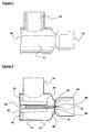
- FIGS 1 and 2 show a first embodiment of the PEEP valve according to the invention.
- the PEEP valve comprises a cylindrical housing 12, which has an inlet port 14 formed at one end of the housing 12 and is sealed by a closure 20 at the other end, and an outlet port 16 that branches perpendicularly from the side wall of the housing 12.
- the housing 12 and closure 20 together define a valve chamber 18, and the housing 12 and inlet port 14 are connected by a neck portion that has an annular valve seat 19 extending inwardly from its interior surface.
- the housing 12, inlet port 14 and outlet port 16 are formed integrally by injection moulding a suitable plastics material.
- the closure 20 is formed separately, also by injection moulding a suitable plastics material.
- the closure 20 comprises a circular disc, and an annular skirt extending perpendicularly from the disc.
- the annular skirt is closely received within the end of the housing 12 opposite the inlet port 14 so that the circular disc abuts that end of the housing 12 and forms an end wall of the valve chamber 18.
- a guide formation 22 is formed integrally with the closure 20 and extends from the inwardly facing surface of the closure 20 towards the inlet port 14.
- the guide formation 22 comprises a central channel of rectangular cross-section and a plurality of support struts 24.
- the central channel of the guide formation 22 has an open end adjacent to the inlet port 14 and receives a shaft 30 of rectangular cross-section so that the shaft 30 is able to move reciprocally within the channel.
- a constant force spring (not visible in Figure 2 ) is mounted on the guide formation 22 and biases the shaft 30 towards the valve seat 19 at a constant force.
- a cylindrical rod 32 of smaller cross-section than the shaft 30 extends co-axially from the end of the shaft 30 that is adjacent to the valve seat 19.
- the cylindrical rod 32 is secured within a central bore of a sealing disc 40 so that the sealing disc 40 is biased into engagement with the valve seat 19.
- the sealing disc 40 has two groups of apertures, each group of apertures being occluded by a closure of flexible material 44, as shown more clearly in Figures 4a, 4b, 5a and 5b .
- the closures of flexible material 44 are attached to the centre of the sealing disc by a retainer 46.
- the retainer 46 is fastened within the central bore of the sealing disc 40 so that an edge of each closure 44 is clamped to the sealing disc 40.
- the retainer 46 has a central bore within which the cylindrical rod 32 is fixed.
- the inlet port 14 of the PEEP valve is connected to an artificial respiratory circuit such that the exhaled breath of a patient is supplied to the inlet port 14.
- exhaled breath at the inlet port 14 above a pre-determined expiration pressure which is determined by the constant force spring, will cause the shaft 30 and sealing disc 40 to move away from the valve seat 19. Exhaled breath will then exit the PEEP valve through the outlet port 16.
- FIGS 4a and 4b show the sealing disc 40, closures of flexible material 44 and retainer 46 at rest.
- the sealing disc 40 is circular in shape and is formed in a relatively rigid plastics material so that the sealing disc 40 retains its shape during normal use of the PEEP valve.
- the sealing disc 40 has a central bore and two diametrically opposed groups of four apertures 42. Each group of apertures 42 is arranged along a curved line that approximately follows the curvature of the peripheral edge of the sealing disc 40.
- the closures of flexible material 44 all form part of a single elastomeric component that overlies the front surface of the sealing disc 40.
- the elastomeric component comprises the pair of closures 44 joined by a narrow central bridge.
- the central bridge has a central bore in which the retainer 46 in received.
- the closures of flexible material 44 are generally elliptical in shape and occlude the two groups of apertures 42 completely when at rest.
- the elastomeric component is formed from a sheet of silicone rubber.
- the retainer 46 has the form of a stud with a rectangular head portion, a relatively short shaft, and a central bore.
- the central bore is tapered towards the tip of the shaft.
- the shaft of the retainer 46 may be urged through the central bores of the elastomeric component and the sealing disc 40 so that the retainer 46 engages the sealing disc 40 with a snap fit, the head portion clamping the central bridge of the elastomeric component to the front surface of the sealing disc 40.
- the head portion of the retainer 46 includes a straight edge adjacent to each closure 44 about which the closure 44 can fold during use.
- closures of flexible material 44 are therefore arranged such that a greater pressure at the rear surface of the sealing disc 40 than at the front surface of the sealing disc 40 will cause each closure 44 to deform about a linear fold which forms adjacent to the retainer 46.
- Deformation of the closures 44 in this way allows respiratory gases to flow through the apertures 42 and hence allows respiratory gases to pass through the sealing disc 40 from the outlet port 16 to the inlet port 14. Such deformation is shown clearly in Figures 5a and 5b .
- the linear fold will form to one side of, and parallel to, the major axis of the elliptical closure 44, and adjacent to the retainer 46.
- a lower pressure differential is required to deform a closure 44 about a linear fold than is required to deform a disc-shaped closure, which is secured to a sealing disc at its centre, into a cone-like shape as for conventional bi-directional flow PEEP valves.
- the PEEP valve according to the invention has a lower resistance to air flow through the sealing disc 40 from the outlet port 16 to the inlet port 14.
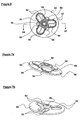
- Figures 6, 7a, 7b and 7c show a sealing disc 50 that forms part of a second embodiment of the PEEP valve according to the invention.
- the second embodiment of the PEEP valve according to the invention is identical to the first embodiment save for the form and arrangement of the sealing disc 50, closures of flexible material 54, and retainer 56.
- the two groups of apertures 42 of the first embodiment are replaced in the second embodiment by three pairs of apertures 52 arranged around the central bore of the sealing disc 50.
- Each pair of apertures 52 is formed by an opening having a rectangular inner portion and a semi-circular outer portion, and a radially extending divider which divides the opening into a pair of apertures 52.
- the front surface of the sealing disc 50 ie the surface over which the closures of flexible material 54 lie) has a raised knife-edge formation that extends around the periphery of each aperture 52.
- the pair of elliptical closures of flexible material 44 of the first embodiment are replaced in the second embodiment by three closures of flexible material 54 which each have a shape similar to, and dimensions slightly larger than, each pair of apertures 52.
- the three closures of flexible material all form part of a single elastomeric component that overlies the raised knife-edges of the front surface of the sealing disc 50, at rest, such that each closure of flexible material 54 occludes a pair of apertures 52 completely.
- the elastomeric component comprises a central portion from which the three closures 54 extend outwardly. The central portion has a central bore which receives the retainer 56.
- the elastomeric component is most preferably formed from a sheet of silicone rubber.
- the retainer 56 of the second embodiment is identical to that of the first embodiment save that the head portion of the retainer 56 is generally triangular in shape.
- Each corner of the triangular head portion has a cut-away portion that receives a raised formation 55 on the front surface of the sealing disc 50.
- the three straight lower edges of the triangular retainer head portion are arranged along the inner straight edges of the closures 54 and the apertures 52, thereby forming edges about which the closures 54 can fold.
- the closures of flexible material 54 of the second embodiment are arranged such that a greater pressure at the rear surface of the sealing disc 50 than at the front surface of the sealing disc 50 will cause each closure 54 to deform about a linear fold which forms along a straight lower edge of the triangular head portion of the retainer 56.
- Deformation of the closures 54 in this way opens the apertures 52 and allows air to pass through the sealing disc 50 from the outlet port to the inlet port of the second embodiment.
- Such deformation is shown clearly in Figures 8a, 8b and 8c .
Landscapes
- Health & Medical Sciences (AREA)
- Pulmonology (AREA)
- General Health & Medical Sciences (AREA)
- Public Health (AREA)
- Anesthesiology (AREA)
- Biomedical Technology (AREA)
- Heart & Thoracic Surgery (AREA)
- Hematology (AREA)
- Life Sciences & Earth Sciences (AREA)
- Animal Behavior & Ethology (AREA)
- Emergency Medicine (AREA)
- Engineering & Computer Science (AREA)
- Veterinary Medicine (AREA)
- Check Valves (AREA)
- Glass Compositions (AREA)
- Multiple-Way Valves (AREA)
- Respiratory Apparatuses And Protective Means (AREA)
- Valve-Gear Or Valve Arrangements (AREA)
- Compressor (AREA)
- Massaging Devices (AREA)
Abstract
Description
- This invention relates to valves that apply Positive End Expiratory Pressure (PEEP) to an artificial respiratory circuit, ie so-called PEEP valves, and in particular to PEEP valves that allow bi-directional flow.
- When a patient is unable to breathe unaided, or requires assistance with breathing, the patient is usually connected to an artificial respiratory circuit including a ventilator programmed by a clinician to deliver an appropriate volume of air, or an air/oxygen mixture, to the patient. In such a respiratory circuit, where the patient is breathing spontaneously but requiring pressure support, it is desirable to prevent the patient from exhaling fully, and therefore the patient's lungs from deflating fully. This is because complete deflation, and subsequent reflation, of the patient's lungs requires a significant amount of the patient's energy.
- Prevention of total exhalation is generally achieved by including a mechanism in the respiratory circuit which only allows exhaled breath above an appropriate exhalation pressure to escape the respiratory circuit. Prevention of total exhalation in this way is known as applying "PEEP" to the respiratory circuit, where "PEEP" refers to Positive End Expiratory Pressure. A widely used method of applying PEEP to a respiratory circuit is by using a so-called PEEP valve to provide a fixed and pre-determined release pressure to the respiratory circuit.
- PEEP valves typically comprise an inlet port for connection to a respiratory circuit, an outlet port for venting the exhaled breath, and a valve mechanism controlling the flow of exhaled breath between the inlet port and the outlet port. A widely used valve mechanism comprises a sealing disc that is spring biased into engagement with an annular valve seat so that exhaled breath at a pressure above a pre-determined exhalation pressure can displace the sealing disc from the valve seat and the air can therefore pass from the inlet port to the outlet port, but air cannot pass from the outlet port to the inlet port. Such PEEP valves thus allow flow of air through the valve in only a single direction.
- PEEP valves are also known that allow the bi-directional flow of air through the valve. Such a construction allows air to be drawn into the respiratory circuit through the PEEP valve. This may be necessary if, for example, the patient requires more air than is being supplied by the ventilator or if the ventilator flow ceases. PEEP valves that allow the bi-directional flow of air through the valve may therefore be safer than conventional unidirectional PEEP valves.
- Currently available bi-directional PEEP valves comprise a first sealing disc that is spring biased into engagement with a valve seat and has a plurality of apertures, and a second flexible sealing disc fixed to the first sealing disc at its centre so that the second sealing disc overlies the first sealing disc and occludes the plurality of apertures. An example of this type of bi-directional PEEP valve is disclosed by
US 4,823,828 . In this way, exhaled breath at a pressure above a pre-determined exhalation pressure can pass from the inlet port to the outlet port, as described above in relation to unidirectional PEEP valves, and air drawn through the outlet port at a pressure sufficient to deform the second sealing disc into a cone-like shape can pass from the outlet port to the inlet port. - A disadvantage of such bidirectional PEEP valves is that the resistance to air flow from the outlet port to the inlet port may be relatively high, particularly at low flow rates, and this may inhibit the operation of the valve.
- There has now been devised an improved PEEP valve which overcomes or substantially mitigates the above-mentioned and/or other disadvantages associated with the prior art.
- According to the invention, there is provided a PEEP valve for use in a respiratory circuit, the valve comprising a housing having an inlet port in fluid communication with an outlet port, a valve seat situated between the inlet port and the outlet port, and a sealing disc movably mounted within the housing and resiliently biased into engagement with the valve seat such that a predetermined positive pressure differential between the inlet and outlet ports, in use, causes the sealing disc to disengage from the valve seat and allow flow of gas from the inlet port to the outlet port, the sealing disc including at least one aperture and there being provided a closure of flexible material that occludes the aperture, characterised in that the closure is clamped to the sealing disc by a retainer such that a negative pressure differential between the inlet and outlet ports, in use, causes the closure to hinge about a substantially linear fold that forms in the closure, thereby exposing the aperture and allowing gas to flow from the outlet port to the inlet port.
- The closure of the PEEP valve according to the invention is adapted to hinge about a linear fold that forms in the closure in response to a negative pressure differential between the inlet and outlet ports. In contrast, the closure of a conventional bi-directional PEEP valve comprises a circular disc that is fixed to the sealing disc at its centre and deforms into a cone-like shape in response to a negative pressure differential between the inlet and outlet ports. The PEEP valve according to the invention is advantageous principally in that a lower negative pressure differential between the inlet and outlet ports is required to deform the closure, for a given orifice size, than for conventional bi-directional PEEP valves. The PEEP valve according to the invention therefore has a lower resistance to air flow from the outlet port to the inlet port than is the case for conventional valves.
- The housing of the PEEP valve according to the invention preferably defines a valve chamber between the outlet port and the valve seat. The sealing disc is most preferably mounted within the valve chamber. In particular, the valve chamber is preferably substantially cylindrical with the inlet port at one end of the valve chamber, the other end of the valve chamber being closed, and the outlet port branching perpendicularly from the side of the valve chamber. In this case, the closed end of the valve chamber preferably includes a mounting for the sealing disc. Most preferably, at least part of the mounting is formed integrally with the closed end of the valve chamber. Most preferably, the closed end of the valve chamber is formed by a closure that is formed integrally with at least part of the mounting for the sealing disc and which is closely received within the housing.
- The mounting for the sealing disc preferably comprises a channel of constant cross-section that has an open end for receiving a shaft so that the shaft is able to move reciprocally within the channel. The end of the shaft that projects from the open end of the channel is preferably fixed to the sealing disc. Most preferably, the shaft has a rod extending co-axially from the end of the shaft which is fixed within a central bore of the sealing disc.
- The valve preferably includes resilient means for biasing the sealing disc into engagement with the valve seat. The resilient means is preferably a spring and is most preferably a constant force spring. Preferably, the spring is mounted on the mounting for the sealing disc, and preferably acts on the end of the shaft remote from the sealing disc.
- The valve seat is preferably a raised formation on the interior surface of the housing. Most preferably, the valve seat is generally annular in form and defines a central opening. The sealing disc preferably engages the valve seat so as to seal the opening defined by the valve seat. The valve seat is preferably annular in shape, and the sealing disc is preferably circular in shape.
- The sealing disc preferably includes two or more apertures, and most preferably six or more apertures. The PEEP valve may therefore include two or more closures, each closure occluding one or more apertures. In preferred embodiments, the apertures are arranged in groups, each group of apertures cooperating with one of two or more closures. This arrangement is advantageous because a closure occluding a group of two or more apertures is much less likely to be drawn through those apertures by high flow rates from the inlet port to the outlet port than a closure occluding a single, larger aperture.
- In a preferred embodiment, the sealing disc is provided with two diametrically opposed groups of apertures, and each group of apertures is occluded by a single closure, such that the PEEP valve has a pair of diametrically opposed closures. Most preferably, each of these closures is generally elliptical in shape.
- The closure(s) preferably overlie the surface of the sealing disc that faces in the direction of the inlet port. Each closure may overlie a raised formation that extends about the perimeter of the aperture, or apertures, occluded by that closure. In this case, each closure preferably overlies an upper edge of the raised formation.
- Where the sealing disc includes two or more closures, each closure may be a distinct component fixed to the sealing disc. Most preferably, however, the closures of the PEEP valve all form part of a single closure component that is fixed to the sealing disc. Each closure, or the closure component, is preferably formed in an elastomeric material, such as silicone rubber, and is most preferably formed from a sheet of silicone rubber.
- In a preferred embodiment, the retainer has a central bore for engagement with the shaft of the sealing disc mounting. The retainer preferably engages the shaft and captivates the closure component in close abutment with the sealing disc.
- The linear fold in each closure, which is caused by the negative pressure differential between the inlet and outlet ports, will form across the closure, normally adjacent the region of the closure that is fixed to the sealing disc.
- Each closure is therefore preferably fixed to the sealing disc at one edge of the closure and beyond the periphery of the aperture, or apertures, that the closure occludes. To facilitate the formation of a linear fold, each closure may be fixed, and most preferably clamped, by a retainer with a straight edge adjacent to the closure about which the linear fold can form.
- The invention will now be described in greater detail, by way of illustration only, with reference to the accompanying drawings, in which
-
Figure 1 is a side view of a first embodiment of a PEEP valve according to the invention; -
Figure 2 is a cross-sectional view of the PEEP valve ofFigure 1 ; -
Figure 3a is a view similar to that ofFigure 2 of the PEEP valve during exhalation through the valve; -
Figure 3b is a view similar to that ofFigure 2 of the PEEP valve during inhalation through the valve; -
Figure 4a is a perspective view of the front face of a sealing disc, which forms part of the first embodiment of a PEEP valve according to the invention, at rest; -
Figure 4b is a perspective view of the rear face of the sealing disc of the first embodiment at rest; -
Figure 5a is a perspective view of the front face of the sealing disc of the first embodiment during inhalation through the valve; -
Figure 5b is a perspective view of the rear face of the sealing disc of the first embodiment during inhalation through the valve; -
Figure 6 is a frontal view, showing hidden detail, of a sealing disc that forms part of a second embodiment of a PEEP valve according to the invention; -
Figure 7a is a perspective view of the front face of the sealing disc of the second embodiment at rest; -
Figure 7b is a perspective view of the rear face of the sealing disc of the second embodiment at rest; -
Figure 7c is a cross-sectional view, along the line VII-VII inFigure 6 , of the sealing disc of the second embodiment at rest; -
Figure 8a is a perspective view of the front face of the sealing disc of the second embodiment during inhalation through the valve; -
Figure 8b is a perspective view of the rear face of the sealing disc of the second embodiment during inhalation through the valve; and -
Figure 8c is a cross-sectional view, along the line VII-VII inFigure 6 , of the sealing disc of the second embodiment during inhalation through the valve. -
Figures 1 and 2 show a first embodiment of the PEEP valve according to the invention. The PEEP valve comprises acylindrical housing 12, which has aninlet port 14 formed at one end of thehousing 12 and is sealed by aclosure 20 at the other end, and anoutlet port 16 that branches perpendicularly from the side wall of thehousing 12. Thehousing 12 andclosure 20 together define avalve chamber 18, and thehousing 12 andinlet port 14 are connected by a neck portion that has anannular valve seat 19 extending inwardly from its interior surface. Thehousing 12,inlet port 14 andoutlet port 16 are formed integrally by injection moulding a suitable plastics material. Theclosure 20 is formed separately, also by injection moulding a suitable plastics material. - The
closure 20 comprises a circular disc, and an annular skirt extending perpendicularly from the disc. The annular skirt is closely received within the end of thehousing 12 opposite theinlet port 14 so that the circular disc abuts that end of thehousing 12 and forms an end wall of thevalve chamber 18. - A
guide formation 22 is formed integrally with theclosure 20 and extends from the inwardly facing surface of theclosure 20 towards theinlet port 14. Theguide formation 22 comprises a central channel of rectangular cross-section and a plurality of support struts 24. The central channel of theguide formation 22 has an open end adjacent to theinlet port 14 and receives ashaft 30 of rectangular cross-section so that theshaft 30 is able to move reciprocally within the channel. A constant force spring (not visible inFigure 2 ) is mounted on theguide formation 22 and biases theshaft 30 towards thevalve seat 19 at a constant force. - A
cylindrical rod 32 of smaller cross-section than theshaft 30 extends co-axially from the end of theshaft 30 that is adjacent to thevalve seat 19. Thecylindrical rod 32 is secured within a central bore of asealing disc 40 so that thesealing disc 40 is biased into engagement with thevalve seat 19. In this embodiment, thesealing disc 40 has two groups of apertures, each group of apertures being occluded by a closure offlexible material 44, as shown more clearly inFigures 4a, 4b, 5a and 5b . The closures offlexible material 44 are attached to the centre of the sealing disc by aretainer 46. Theretainer 46 is fastened within the central bore of thesealing disc 40 so that an edge of eachclosure 44 is clamped to thesealing disc 40. Theretainer 46 has a central bore within which thecylindrical rod 32 is fixed. Thesealing disc 40, closures offlexible material 44, andretainer 46 are described more fully below in relation toFigures 4a, 4b, 5a and 5b . - In use, the
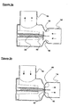
inlet port 14 of the PEEP valve is connected to an artificial respiratory circuit such that the exhaled breath of a patient is supplied to theinlet port 14. As shown inFigure 3a , exhaled breath at theinlet port 14 above a pre-determined expiration pressure, which is determined by the constant force spring, will cause theshaft 30 and sealingdisc 40 to move away from thevalve seat 19. Exhaled breath will then exit the PEEP valve through theoutlet port 16. - In the event that it is necessary for the patient to draw air through the PEEP valve from the
outlet port 16 to theinlet port 14, the patient will lower the air pressure at theinlet port 14. As shown inFigure 3b , this will cause the closures offlexible material 44 to deform away from thesealing disc 40 and the two groups of apertures, and air to be drawn from theoutlet port 16 to theinlet port 14. - The
sealing disc 40, closures offlexible material 44 andretainer 46 are all shown more clearly inFigures 4a, 4b, 5a and 5b . -
Figures 4a and 4b show thesealing disc 40, closures offlexible material 44 andretainer 46 at rest. Thesealing disc 40 is circular in shape and is formed in a relatively rigid plastics material so that thesealing disc 40 retains its shape during normal use of the PEEP valve. Thesealing disc 40 has a central bore and two diametrically opposed groups of fourapertures 42. Each group ofapertures 42 is arranged along a curved line that approximately follows the curvature of the peripheral edge of thesealing disc 40. - The closures of
flexible material 44 all form part of a single elastomeric component that overlies the front surface of thesealing disc 40. The elastomeric component comprises the pair ofclosures 44 joined by a narrow central bridge. The central bridge has a central bore in which theretainer 46 in received. The closures offlexible material 44 are generally elliptical in shape and occlude the two groups ofapertures 42 completely when at rest. In this embodiment, the elastomeric component is formed from a sheet of silicone rubber. - The
retainer 46 has the form of a stud with a rectangular head portion, a relatively short shaft, and a central bore. The central bore is tapered towards the tip of the shaft. The shaft of theretainer 46 may be urged through the central bores of the elastomeric component and thesealing disc 40 so that theretainer 46 engages thesealing disc 40 with a snap fit, the head portion clamping the central bridge of the elastomeric component to the front surface of thesealing disc 40. The head portion of theretainer 46 includes a straight edge adjacent to eachclosure 44 about which theclosure 44 can fold during use. - The closures of
flexible material 44 are therefore arranged such that a greater pressure at the rear surface of thesealing disc 40 than at the front surface of thesealing disc 40 will cause eachclosure 44 to deform about a linear fold which forms adjacent to theretainer 46. Deformation of theclosures 44 in this way allows respiratory gases to flow through theapertures 42 and hence allows respiratory gases to pass through thesealing disc 40 from theoutlet port 16 to theinlet port 14. Such deformation is shown clearly inFigures 5a and 5b . - The linear fold will form to one side of, and parallel to, the major axis of the
elliptical closure 44, and adjacent to theretainer 46. A lower pressure differential is required to deform aclosure 44 about a linear fold than is required to deform a disc-shaped closure, which is secured to a sealing disc at its centre, into a cone-like shape as for conventional bi-directional flow PEEP valves. - The following table sets out the results of a test of the pressure resistance to air flow from the outlet valve to the inlet valve of a PEEP valve incorporating a conventional circular deformable disc that deforms into a cone-like shape ("Disc Resistance"), and a PEEP valve similar to the first embodiment of the invention described above having closures that deform about a linear fold ("Butterfly Vent Resistance").
Table 1 Flow (I/m) Disc Resistance (cmH2O) Butterfly Vent Resistance (cmH2O) Reduction in Resistance achieved by changing to the Butterfly Vent (%) 5 0.21 0.19 14 10 0.61 0.40 34 20 1.65 0.75 55 40 3.40 1.60 53 60 5.19 2.64 49 80 7.04 3.90 45 100 9.24 5.55 40 120 11.8 7.20 39 - Clearly, the PEEP valve according to the invention has a lower resistance to air flow through the
sealing disc 40 from theoutlet port 16 to theinlet port 14. -
Figures 6, 7a, 7b and7c show asealing disc 50 that forms part of a second embodiment of the PEEP valve according to the invention. The second embodiment of the PEEP valve according to the invention is identical to the first embodiment save for the form and arrangement of thesealing disc 50, closures offlexible material 54, andretainer 56. - The two groups of
apertures 42 of the first embodiment are replaced in the second embodiment by three pairs ofapertures 52 arranged around the central bore of thesealing disc 50. Each pair ofapertures 52 is formed by an opening having a rectangular inner portion and a semi-circular outer portion, and a radially extending divider which divides the opening into a pair ofapertures 52. The front surface of the sealing disc 50 (ie the surface over which the closures offlexible material 54 lie) has a raised knife-edge formation that extends around the periphery of eachaperture 52. - The pair of elliptical closures of
flexible material 44 of the first embodiment are replaced in the second embodiment by three closures offlexible material 54 which each have a shape similar to, and dimensions slightly larger than, each pair ofapertures 52. The three closures of flexible material all form part of a single elastomeric component that overlies the raised knife-edges of the front surface of thesealing disc 50, at rest, such that each closure offlexible material 54 occludes a pair ofapertures 52 completely. The elastomeric component comprises a central portion from which the threeclosures 54 extend outwardly. The central portion has a central bore which receives theretainer 56. The elastomeric component is most preferably formed from a sheet of silicone rubber. - The
retainer 56 of the second embodiment is identical to that of the first embodiment save that the head portion of theretainer 56 is generally triangular in shape. Each corner of the triangular head portion has a cut-away portion that receives a raisedformation 55 on the front surface of thesealing disc 50. The three straight lower edges of the triangular retainer head portion are arranged along the inner straight edges of theclosures 54 and theapertures 52, thereby forming edges about which theclosures 54 can fold. - As for the first embodiment, the closures of
flexible material 54 of the second embodiment are arranged such that a greater pressure at the rear surface of thesealing disc 50 than at the front surface of thesealing disc 50 will cause eachclosure 54 to deform about a linear fold which forms along a straight lower edge of the triangular head portion of theretainer 56. Deformation of theclosures 54 in this way opens theapertures 52 and allows air to pass through thesealing disc 50 from the outlet port to the inlet port of the second embodiment. Such deformation is shown clearly inFigures 8a, 8b and 8c .
Claims (22)
- A PEEP valve for use in a respiratory circuit, the valve comprising a housing (12) having an inlet port (14) in fluid communication with an outlet port (16), a valve seat (19) situated between the inlet port (14) and the outlet port (16), and a sealing disc (40,50) movably mounted within the housing (12) and resiliently biased into engagement with the valve seat (19) such that a predetermined positive pressure differential between the inlet and outlet ports (14,16), in use, causes the sealing disc (40,50) to disengage from the valve seat (19) and allow flow of gas from the inlet port (14) to the outlet port (16), the sealing disc (40,50) including at least one aperture (42,52) and there being provided a closure (44,54) of flexible material that occludes the aperture,
characterised in that the closure (44,54) is clamped to the sealing disc (40,50) by a retainer (46,56) such that a negative pressure differential between the inlet and outlet ports (14,16), in use, causes the closure (44,54) to hinge about a substantially linear fold that forms in the closure (44,54), thereby exposing the aperture and allowing gas to flow from the outlet port (16) to the inlet port (14). - A PEEP valve as claimed in Claim 1, wherein the retainer (46,56) includes a straight edge adjacent to the closure (44,54) about which the substantially linear fold can form.
- A PEEP valve as claimed in Claim 1 or Claim 2, wherein the housing (12) defines a valve chamber (18) between the outlet port (16) and the valve seat (19), and the sealing disc (40,50) is mounted within the valve chamber (18).
- A PEEP valve as claimed in Claim 3, wherein the valve chamber (18) is substantially cylindrical with the inlet port (14) at one end of the valve chamber (18), the other end of the valve chamber (18) being closed, and the outlet port (16) branching perpendicularly from the side of the valve chamber (18).
- A PEEP valve as claimed in Claim 4, wherein the closed end of the valve chamber (18) includes a mounting for the sealing disc (40,50).
- A PEEP valve as claimed in Claim 5, wherein the closed end of the valve chamber (18) is formed by a closure (20) that is formed integrally with at least part of the mounting for the sealing disc (40,50) and which is closely received within the housing (12).
- A PEEP valve as claimed in any preceding claim, wherein the mounting for the sealing disc (40,50) comprises a channel of constant cross-section that has an open end for receiving a shaft (30) so that the shaft (30) is able to move reciprocally within the channel, the end of the shaft (30) that projects from the open end of the channel being fixed to the sealing disc (40,50).
- A PEEP valve as claimed in Claim 7, wherein the shaft (30) has a rod (32) extending co-axially from the end of the shaft (30) which is fixed within a central bore of the sealing disc (40,50).
- A PEEP valve as claimed in any preceding claim, wherein the valve includes resilient means for biasing the sealing disc (40,50) into engagement with the valve seat (19).
- A PEEP valve as claimed in Claim 9, wherein the resilient means is a constant force spring.
- A PEEP valve as claimed in any preceding claim, wherein the valve seat (19) is a raised formation on the interior surface of the housing (12).
- A PEEP valve as claimed in Claim 11, wherein the valve seat (19) is generally annular in form and defines a central opening, and the sealing disc (40,50) engages the valve seat (19) so as to seal the opening defined by the valve seat (19).
- A PEEP valve as claimed in any preceding claim, wherein the closure (44,54) overlies the surface of the sealing disc (40,50) that faces in the direction of the inlet port (14).
- A PEEP valve as claimed in any preceding claim, wherein the closure (44,54) is formed in an elastomeric material.
- A PEEP valve as claimed in any preceding claim, wherein the closure (44,54) is fixed to the sealing disc (40,50) at one edge of the closure (44,54) and beyond the periphery of the aperture that the closure (44,54) occludes.
- A PEEP valve as claimed in any preceding claim, wherein the sealing disc (40,50) includes two or more apertures (42,52).
- A PEEP valve as claimed in Claim 16, wherein the sealing disc (40,50) includes six or more apertures (42,52).
- A PEEP valve as claimed in Claim 16 or Claim 17, wherein the apertures (42,52) are arranged in groups, each group of apertures (42,52) cooperating with one of two or more closures (44,54).
- A PEEP valve as claimed in Claim 18, wherein each closure (44,54) occludes two or more apertures (42,52).
- A PEEP valve as claimed in Claim 19, wherein the sealing disc (40,50) is provided with two diametrically opposed groups of apertures (42,52), and each group of apertures (42,52) is occluded by a single closure (44,54), such that the PEEP valve has a pair of diametrically opposed closures (44,54).
- A PEEP valve as claimed in Claim 20, wherein each of the diametrically opposed closures (44,54) is generally elliptical in shape.
- A PEEP valve as claimed in any one of Claims 18 to 21, wherein the two or more closures (44,54) form part of a single closure component that is fixed to the sealing disc (40,50).
Applications Claiming Priority (2)
| Application Number | Priority Date | Filing Date | Title |
|---|---|---|---|
| GBGB0321266.9A GB0321266D0 (en) | 2003-09-11 | 2003-09-11 | Improvements relating to PEEP valves |
| PCT/GB2004/003798 WO2005025659A1 (en) | 2003-09-11 | 2004-09-07 | Peep valve |
Publications (2)
| Publication Number | Publication Date |
|---|---|
| EP1663367A1 EP1663367A1 (en) | 2006-06-07 |
| EP1663367B1 true EP1663367B1 (en) | 2010-05-19 |
Family
ID=29226885
Family Applications (1)
| Application Number | Title | Priority Date | Filing Date |
|---|---|---|---|
| EP04768345A Expired - Lifetime EP1663367B1 (en) | 2003-09-11 | 2004-09-07 | Peep valve |
Country Status (6)
| Country | Link |
|---|---|
| EP (1) | EP1663367B1 (en) |
| AT (1) | ATE468143T1 (en) |
| DE (1) | DE602004027265D1 (en) |
| ES (1) | ES2346536T3 (en) |
| GB (2) | GB0321266D0 (en) |
| WO (1) | WO2005025659A1 (en) |
Families Citing this family (6)
| Publication number | Priority date | Publication date | Assignee | Title |
|---|---|---|---|---|
| GB2433701B (en) | 2005-12-29 | 2010-03-24 | Medinnova As | Valve for a breathing apparatus |
| DE102007012285B3 (en) * | 2007-03-08 | 2008-02-28 | Filt Lungen- Und Thoraxdiagnostik Gmbh | Method for flow control in flow pipe, involves arranging valve plate with valve seat in housing in front of inlet opening, pressed against flowing direction of gases with force strength |
| GB2549437B (en) * | 2011-12-09 | 2018-02-28 | Intersurgical Ag | Valve for respiratory masks |
| CN107961042B (en) * | 2017-12-01 | 2023-06-09 | 无锡市尚沃医疗电子股份有限公司 | Intelligent expiration sampling method and device |
| US20220139255A1 (en) * | 2020-10-30 | 2022-05-05 | Innovative Voice Sciences and Strategies, LLC | Devices, systems, and methods for voice therapy |
| GB2602500B (en) * | 2021-01-05 | 2024-10-09 | Secr Defence | Respiratory device |
Family Cites Families (11)
| Publication number | Priority date | Publication date | Assignee | Title |
|---|---|---|---|---|
| GB791005A (en) * | 1955-04-07 | 1958-02-19 | British Oxygen Co Ltd | Improvements in or relating to fluid-actuated valves |
| US3435839A (en) * | 1965-05-21 | 1969-04-01 | Elder Oxygen Co Inc | Backflow bypassing valve for breathing apparatus |
| US4257453A (en) * | 1979-04-06 | 1981-03-24 | Ruth L. Hesse | Peep valve with improved vibration damping |
| US4428392A (en) * | 1981-12-24 | 1984-01-31 | Protection, Inc. | Breathing valve |
| US5002050A (en) * | 1986-09-17 | 1991-03-26 | Mcginnis Gerald E | Medical gas flow control valve, system and method |
| US4823828A (en) * | 1987-05-28 | 1989-04-25 | Mcginnis Gerald E | Pressure relief valve |
| US5103854A (en) * | 1990-01-22 | 1992-04-14 | Vernay Laboratories, Inc. | Low pressure check valve for artificial respiration devices |
| CA2091878A1 (en) * | 1990-10-17 | 1992-04-18 | James C. Bailey | Low pressure check valve for artificial respiration devices |
| US5584288A (en) * | 1994-02-03 | 1996-12-17 | Baldwin; Gene R. | Multi-stage mouth-to-mouth resuscitator valve |
| AU778777B2 (en) * | 1999-09-23 | 2004-12-23 | Fisher & Paykel Healthcare Limited | Breathing assistance apparatus |
| DE10126807C2 (en) * | 2001-06-01 | 2003-12-04 | Pari Gmbh | Inhalation therapy device with a valve to limit the flow of inspiration |
-
2003
- 2003-09-11 GB GBGB0321266.9A patent/GB0321266D0/en not_active Ceased
-
2004
- 2004-09-07 EP EP04768345A patent/EP1663367B1/en not_active Expired - Lifetime
- 2004-09-07 DE DE602004027265T patent/DE602004027265D1/en not_active Expired - Lifetime
- 2004-09-07 ES ES04768345T patent/ES2346536T3/en not_active Expired - Lifetime
- 2004-09-07 AT AT04768345T patent/ATE468143T1/en not_active IP Right Cessation
- 2004-09-07 WO PCT/GB2004/003798 patent/WO2005025659A1/en active Search and Examination
- 2004-09-07 GB GB0419780A patent/GB2406285B/en not_active Expired - Lifetime
Also Published As
| Publication number | Publication date |
|---|---|
| ES2346536T3 (en) | 2010-10-18 |
| WO2005025659A1 (en) | 2005-03-24 |
| GB0419780D0 (en) | 2004-10-06 |
| ATE468143T1 (en) | 2010-06-15 |
| GB0321266D0 (en) | 2003-10-08 |
| GB2406285A (en) | 2005-03-30 |
| DE602004027265D1 (en) | 2010-07-01 |
| EP1663367A1 (en) | 2006-06-07 |
| GB2406285B (en) | 2007-08-22 |
Similar Documents
| Publication | Publication Date | Title |
|---|---|---|
| US7066177B2 (en) | Exhalation valves | |
| US4958633A (en) | Valve for respirator | |
| US4454893A (en) | Low-noise diaphragm for use in exhalation valve | |
| US4606340A (en) | Combined pressure compensating exhalation and anti-suffocation valve | |
| EP1399222B1 (en) | Respirator valve | |
| US3933171A (en) | Anesthesia breathing circuit with positive end expiratory pressure valve | |
| FI105162B (en) | Breathing intensifier and valve coupled to a channel of a breathing intensifier | |
| US4712580A (en) | Exhalation valve assembly | |
| US3990439A (en) | Protective breathing apparatus and valve therefor | |
| EP2229207B1 (en) | Improvements relating to anti-asphyxiation valves | |
| US3942547A (en) | Valves | |
| US20070267019A1 (en) | Manually operated respiration apparatus, and balloon unit and valve housing for a manually operated respiration apparatus | |
| US5645047A (en) | Inhalation mask | |
| US10682482B2 (en) | Fresh air and anti-asphyxiation assembly | |
| WO2009089807A1 (en) | Low-noise application interface with integrated peep valve | |
| EP1663367B1 (en) | Peep valve | |
| US3812878A (en) | Fail-safe breathing circuit and valve assembly for use therewith | |
| WO2020173505A1 (en) | Fluid unidirectional flow structure, check assembly, and respiratory device | |
| EP0143618B1 (en) | Exhalation valve | |
| CN222467803U (en) | Safety valve of breathing machine | |
| US20240358954A1 (en) | Medical Face Mask | |
| DE102008005020A1 (en) | Breathing device for patients with breathing difficulties comprises a controllable valve and a breathing mask |
Legal Events
| Date | Code | Title | Description |
|---|---|---|---|
| PUAI | Public reference made under article 153(3) epc to a published international application that has entered the european phase |
Free format text: ORIGINAL CODE: 0009012 |
|
| 17P | Request for examination filed |
Effective date: 20060307 |
|
| AK | Designated contracting states |
Kind code of ref document: A1 Designated state(s): AT BE BG CH CY CZ DE DK EE ES FI FR GB GR HU IE IT LI LU MC NL PL PT RO SE SI SK TR |
|
| DAX | Request for extension of the european patent (deleted) | ||
| RAP1 | Party data changed (applicant data changed or rights of an application transferred) |
Owner name: INTERSURGICAL AG |
|
| 17Q | First examination report despatched |
Effective date: 20070903 |
|
| GRAP | Despatch of communication of intention to grant a patent |
Free format text: ORIGINAL CODE: EPIDOSNIGR1 |
|
| GRAS | Grant fee paid |
Free format text: ORIGINAL CODE: EPIDOSNIGR3 |
|
| GRAA | (expected) grant |
Free format text: ORIGINAL CODE: 0009210 |
|
| AK | Designated contracting states |
Kind code of ref document: B1 Designated state(s): AT BE BG CH CY CZ DE DK EE ES FI FR GR HU IE IT LI LU MC NL PL PT RO SE SI SK TR |
|
| REG | Reference to a national code |
Ref country code: CH Ref legal event code: EP |
|
| REG | Reference to a national code |
Ref country code: IE Ref legal event code: FG4D |
|
| REF | Corresponds to: |
Ref document number: 602004027265 Country of ref document: DE Date of ref document: 20100701 Kind code of ref document: P |
|
| REG | Reference to a national code |
Ref country code: NL Ref legal event code: VDEP Effective date: 20100519 |
|
| REG | Reference to a national code |
Ref country code: ES Ref legal event code: FG2A Ref document number: 2346536 Country of ref document: ES Kind code of ref document: T3 |
|
| PG25 | Lapsed in a contracting state [announced via postgrant information from national office to epo] |
Ref country code: SE Free format text: LAPSE BECAUSE OF FAILURE TO SUBMIT A TRANSLATION OF THE DESCRIPTION OR TO PAY THE FEE WITHIN THE PRESCRIBED TIME-LIMIT Effective date: 20100519 |
|
| PG25 | Lapsed in a contracting state [announced via postgrant information from national office to epo] |
Ref country code: SI Free format text: LAPSE BECAUSE OF FAILURE TO SUBMIT A TRANSLATION OF THE DESCRIPTION OR TO PAY THE FEE WITHIN THE PRESCRIBED TIME-LIMIT Effective date: 20100519 Ref country code: AT Free format text: LAPSE BECAUSE OF FAILURE TO SUBMIT A TRANSLATION OF THE DESCRIPTION OR TO PAY THE FEE WITHIN THE PRESCRIBED TIME-LIMIT Effective date: 20100519 Ref country code: FI Free format text: LAPSE BECAUSE OF FAILURE TO SUBMIT A TRANSLATION OF THE DESCRIPTION OR TO PAY THE FEE WITHIN THE PRESCRIBED TIME-LIMIT Effective date: 20100519 |
|
| PG25 | Lapsed in a contracting state [announced via postgrant information from national office to epo] |
Ref country code: CY Free format text: LAPSE BECAUSE OF FAILURE TO SUBMIT A TRANSLATION OF THE DESCRIPTION OR TO PAY THE FEE WITHIN THE PRESCRIBED TIME-LIMIT Effective date: 20100519 Ref country code: GR Free format text: LAPSE BECAUSE OF FAILURE TO SUBMIT A TRANSLATION OF THE DESCRIPTION OR TO PAY THE FEE WITHIN THE PRESCRIBED TIME-LIMIT Effective date: 20100820 Ref country code: PL Free format text: LAPSE BECAUSE OF FAILURE TO SUBMIT A TRANSLATION OF THE DESCRIPTION OR TO PAY THE FEE WITHIN THE PRESCRIBED TIME-LIMIT Effective date: 20100519 |
|
| PG25 | Lapsed in a contracting state [announced via postgrant information from national office to epo] |
Ref country code: NL Free format text: LAPSE BECAUSE OF FAILURE TO SUBMIT A TRANSLATION OF THE DESCRIPTION OR TO PAY THE FEE WITHIN THE PRESCRIBED TIME-LIMIT Effective date: 20100519 Ref country code: EE Free format text: LAPSE BECAUSE OF FAILURE TO SUBMIT A TRANSLATION OF THE DESCRIPTION OR TO PAY THE FEE WITHIN THE PRESCRIBED TIME-LIMIT Effective date: 20100519 Ref country code: PT Free format text: LAPSE BECAUSE OF FAILURE TO SUBMIT A TRANSLATION OF THE DESCRIPTION OR TO PAY THE FEE WITHIN THE PRESCRIBED TIME-LIMIT Effective date: 20100920 Ref country code: DK Free format text: LAPSE BECAUSE OF FAILURE TO SUBMIT A TRANSLATION OF THE DESCRIPTION OR TO PAY THE FEE WITHIN THE PRESCRIBED TIME-LIMIT Effective date: 20100519 |
|
| PG25 | Lapsed in a contracting state [announced via postgrant information from national office to epo] |
Ref country code: BE Free format text: LAPSE BECAUSE OF FAILURE TO SUBMIT A TRANSLATION OF THE DESCRIPTION OR TO PAY THE FEE WITHIN THE PRESCRIBED TIME-LIMIT Effective date: 20100519 Ref country code: RO Free format text: LAPSE BECAUSE OF FAILURE TO SUBMIT A TRANSLATION OF THE DESCRIPTION OR TO PAY THE FEE WITHIN THE PRESCRIBED TIME-LIMIT Effective date: 20100519 Ref country code: CZ Free format text: LAPSE BECAUSE OF FAILURE TO SUBMIT A TRANSLATION OF THE DESCRIPTION OR TO PAY THE FEE WITHIN THE PRESCRIBED TIME-LIMIT Effective date: 20100519 Ref country code: SK Free format text: LAPSE BECAUSE OF FAILURE TO SUBMIT A TRANSLATION OF THE DESCRIPTION OR TO PAY THE FEE WITHIN THE PRESCRIBED TIME-LIMIT Effective date: 20100519 |
|
| PLBE | No opposition filed within time limit |
Free format text: ORIGINAL CODE: 0009261 |
|
| STAA | Information on the status of an ep patent application or granted ep patent |
Free format text: STATUS: NO OPPOSITION FILED WITHIN TIME LIMIT |
|
| 26N | No opposition filed |
Effective date: 20110222 |
|
| PG25 | Lapsed in a contracting state [announced via postgrant information from national office to epo] |
Ref country code: MC Free format text: LAPSE BECAUSE OF NON-PAYMENT OF DUE FEES Effective date: 20100930 |
|
| REG | Reference to a national code |
Ref country code: CH Ref legal event code: PL |
|
| REG | Reference to a national code |
Ref country code: DE Ref legal event code: R097 Ref document number: 602004027265 Country of ref document: DE Effective date: 20110221 |
|
| PG25 | Lapsed in a contracting state [announced via postgrant information from national office to epo] |
Ref country code: CH Free format text: LAPSE BECAUSE OF NON-PAYMENT OF DUE FEES Effective date: 20100930 Ref country code: LI Free format text: LAPSE BECAUSE OF NON-PAYMENT OF DUE FEES Effective date: 20100930 Ref country code: IE Free format text: LAPSE BECAUSE OF NON-PAYMENT OF DUE FEES Effective date: 20100907 |
|
| PG25 | Lapsed in a contracting state [announced via postgrant information from national office to epo] |
Ref country code: HU Free format text: LAPSE BECAUSE OF FAILURE TO SUBMIT A TRANSLATION OF THE DESCRIPTION OR TO PAY THE FEE WITHIN THE PRESCRIBED TIME-LIMIT Effective date: 20101120 Ref country code: LU Free format text: LAPSE BECAUSE OF NON-PAYMENT OF DUE FEES Effective date: 20100907 Ref country code: BG Free format text: LAPSE BECAUSE OF FAILURE TO SUBMIT A TRANSLATION OF THE DESCRIPTION OR TO PAY THE FEE WITHIN THE PRESCRIBED TIME-LIMIT Effective date: 20100519 |
|
| PG25 | Lapsed in a contracting state [announced via postgrant information from national office to epo] |
Ref country code: TR Free format text: LAPSE BECAUSE OF FAILURE TO SUBMIT A TRANSLATION OF THE DESCRIPTION OR TO PAY THE FEE WITHIN THE PRESCRIBED TIME-LIMIT Effective date: 20100519 |
|
| PG25 | Lapsed in a contracting state [announced via postgrant information from national office to epo] |
Ref country code: BG Free format text: LAPSE BECAUSE OF FAILURE TO SUBMIT A TRANSLATION OF THE DESCRIPTION OR TO PAY THE FEE WITHIN THE PRESCRIBED TIME-LIMIT Effective date: 20100819 |
|
| REG | Reference to a national code |
Ref country code: FR Ref legal event code: PLFP Year of fee payment: 13 |
|
| REG | Reference to a national code |
Ref country code: FR Ref legal event code: PLFP Year of fee payment: 14 |
|
| REG | Reference to a national code |
Ref country code: FR Ref legal event code: PLFP Year of fee payment: 15 |
|
| P01 | Opt-out of the competence of the unified patent court (upc) registered |
Effective date: 20230524 |
|
| PGFP | Annual fee paid to national office [announced via postgrant information from national office to epo] |
Ref country code: IT Payment date: 20230726 Year of fee payment: 20 |
|
| PGFP | Annual fee paid to national office [announced via postgrant information from national office to epo] |
Ref country code: FR Payment date: 20230720 Year of fee payment: 20 Ref country code: DE Payment date: 20230808 Year of fee payment: 20 |
|
| PGFP | Annual fee paid to national office [announced via postgrant information from national office to epo] |
Ref country code: ES Payment date: 20231017 Year of fee payment: 20 |
|
| REG | Reference to a national code |
Ref country code: DE Ref legal event code: R071 Ref document number: 602004027265 Country of ref document: DE |
|
| REG | Reference to a national code |
Ref country code: ES Ref legal event code: FD2A Effective date: 20240927 |
|
| PG25 | Lapsed in a contracting state [announced via postgrant information from national office to epo] |
Ref country code: ES Free format text: LAPSE BECAUSE OF EXPIRATION OF PROTECTION Effective date: 20240908 |
|
| PG25 | Lapsed in a contracting state [announced via postgrant information from national office to epo] |
Ref country code: ES Free format text: LAPSE BECAUSE OF EXPIRATION OF PROTECTION Effective date: 20240908 |