EP1663015B1 - Knotless suture anchor new - Google Patents
Knotless suture anchor new Download PDFInfo
- Publication number
- EP1663015B1 EP1663015B1 EP04783579A EP04783579A EP1663015B1 EP 1663015 B1 EP1663015 B1 EP 1663015B1 EP 04783579 A EP04783579 A EP 04783579A EP 04783579 A EP04783579 A EP 04783579A EP 1663015 B1 EP1663015 B1 EP 1663015B1
- Authority
- EP
- European Patent Office
- Prior art keywords
- proximal shaft
- collar member
- suture anchor
- inner member
- hole
- Prior art date
- Legal status (The legal status is an assumption and is not a legal conclusion. Google has not performed a legal analysis and makes no representation as to the accuracy of the status listed.)
- Expired - Lifetime
Links
- 229920000785 ultra high molecular weight polyethylene Polymers 0.000 claims description 5
- 239000004699 Ultra-high molecular weight polyethylene Substances 0.000 claims description 4
- 239000000463 material Substances 0.000 claims description 4
- 238000004873 anchoring Methods 0.000 claims description 3
- 229920000271 Kevlar® Polymers 0.000 claims description 2
- 239000004761 kevlar Substances 0.000 claims description 2
- 238000001228 spectrum Methods 0.000 claims description 2
- 238000003780 insertion Methods 0.000 abstract description 9
- 230000037431 insertion Effects 0.000 abstract description 9
- 238000000034 method Methods 0.000 abstract description 3
- 210000001519 tissue Anatomy 0.000 description 33
- 210000000988 bone and bone Anatomy 0.000 description 10
- 210000004872 soft tissue Anatomy 0.000 description 8
- 230000003313 weakening effect Effects 0.000 description 2
- 239000004677 Nylon Substances 0.000 description 1
- 239000000560 biocompatible material Substances 0.000 description 1
- 230000008878 coupling Effects 0.000 description 1
- 238000010168 coupling process Methods 0.000 description 1
- 238000005859 coupling reaction Methods 0.000 description 1
- 238000005553 drilling Methods 0.000 description 1
- 238000012986 modification Methods 0.000 description 1
- 230000004048 modification Effects 0.000 description 1
- 229920001778 nylon Polymers 0.000 description 1
- 238000001356 surgical procedure Methods 0.000 description 1
Images


Classifications
-
- A—HUMAN NECESSITIES
- A61—MEDICAL OR VETERINARY SCIENCE; HYGIENE
- A61B—DIAGNOSIS; SURGERY; IDENTIFICATION
- A61B17/00—Surgical instruments, devices or methods
- A61B17/04—Surgical instruments, devices or methods for suturing wounds; Holders or packages for needles or suture materials
- A61B17/0487—Suture clamps, clips or locks, e.g. for replacing suture knots; Instruments for applying or removing suture clamps, clips or locks
-
- A—HUMAN NECESSITIES
- A61—MEDICAL OR VETERINARY SCIENCE; HYGIENE
- A61B—DIAGNOSIS; SURGERY; IDENTIFICATION
- A61B17/00—Surgical instruments, devices or methods
- A61B17/04—Surgical instruments, devices or methods for suturing wounds; Holders or packages for needles or suture materials
- A61B17/0401—Suture anchors, buttons or pledgets, i.e. means for attaching sutures to bone, cartilage or soft tissue; Instruments for applying or removing suture anchors
- A61B2017/0409—Instruments for applying suture anchors
-
- A—HUMAN NECESSITIES
- A61—MEDICAL OR VETERINARY SCIENCE; HYGIENE
- A61B—DIAGNOSIS; SURGERY; IDENTIFICATION
- A61B17/00—Surgical instruments, devices or methods
- A61B17/04—Surgical instruments, devices or methods for suturing wounds; Holders or packages for needles or suture materials
- A61B17/0401—Suture anchors, buttons or pledgets, i.e. means for attaching sutures to bone, cartilage or soft tissue; Instruments for applying or removing suture anchors
- A61B2017/0414—Suture anchors, buttons or pledgets, i.e. means for attaching sutures to bone, cartilage or soft tissue; Instruments for applying or removing suture anchors having a suture-receiving opening, e.g. lateral opening
-
- A—HUMAN NECESSITIES
- A61—MEDICAL OR VETERINARY SCIENCE; HYGIENE
- A61B—DIAGNOSIS; SURGERY; IDENTIFICATION
- A61B17/00—Surgical instruments, devices or methods
- A61B17/04—Surgical instruments, devices or methods for suturing wounds; Holders or packages for needles or suture materials
- A61B17/0401—Suture anchors, buttons or pledgets, i.e. means for attaching sutures to bone, cartilage or soft tissue; Instruments for applying or removing suture anchors
- A61B2017/0446—Means for attaching and blocking the suture in the suture anchor
- A61B2017/0448—Additional elements on or within the anchor
Definitions
- the present invention relates to suture or surgical anchors for installing same in tissue.
- the present invention relates to a suture anchor for anchoring a second tissue such as soft tissue to a first tissue such as bone without requiring the tying of a knot in the suture.
- suture anchors it is common in the medical arts for medical personnel, such as surgeons, to use suture anchors to facilitate the attachment of soft tissue to bone while performing medical procedures.
- the bone is pre-prepared by drilling a bore hole, within which the suture anchor is subsequently inserted.
- a suture extending from the anchor is either attached to or threaded through the soft tissue so that the soft tissue may be secured to the bone.
- the surgeon must tie off or knot the suture to ensure that the soft tissue remains in place after the medical procedure.
- the suture may be attached to the tissue prior to insertion of the anchor into the bone bore hole. In this case also, a knot must be made in the suture to tie the tissue to the anchor. Often, due to tight clearances, particularly in arthroscopic surgery, it is difficult to manipulate the sutures to tie the knot.
- the present invention relates to a device using a suture anchor to attach soft tissue to bone or other tissue which allows the soft tissue to be secured without tying a knot.
- a knotless suture anchor is provided for anchoring a suture thread to tissue (e.g., bone tissue).
- the suture anchor includes an inner member including a proximal shaft and a distal securing member shaped to secure the inner member to the tissue, the proximal shaft including a first locking part and at least one hole extending therethrough for receiving the suture thread; and a collar member including an axial bore shaped to receive the proximal shaft of the inner member, a second locking part, and at least one hole extending therethrough and assigned to the hole of the proximal shaft of the inner member, the collar member being axially slidable into unlocked and locked positions relative to the proximal shaft of the inner member, the collar member being axially relatively slidable into the locked position only to secure the suture thread.
- the hole of the collar member is aligned with the hole of the proximal shaft of the inner member when the collar member is placed into the unlocked position, the hole of the collar member is misaligned with the hole of the proximal shaft of the inner member when the collar member is placed into the locked position, and the first locking part of the proximal shaft engages with the second locking part of the collar member to axially lock the collar member with respect to the proximal shaft when the collar member is placed into the locked position.
- the suture is first threaded into the first tissue, forming a suture loop through the first tissue.
- the two legs of the suture are then inserted through the holes of the collar member and the inner member, and the anchor is inserted into the second tissue.
- the collar member is moved distally, for example, using a suture anchor insertion tool. This causes the hole of the collar member to come out of alignment with the hole of the inner member, thereby causing the suture to be frictionally secured between the outer surface of the inner member and the inner surface of the collar member. In this manner, the suture may be fixedly secured to the anchor without need for tying a knot in the suture.
- Suture anchor 100 includes an inner member 110 and a slidable collar member 120 configured to be concentrically disposed about inner member 110.
- knotless suture anchor 100 is made from a bio-absorbable material.
- knotless suture anchor 100 may be constructed from any material suitable for securing suture anchor 100 to tissue.
- suture anchor 100 may be constructed from a non-bioabsorbable and/or bio-compatible material.
- Insertion tool 900 is provided for inserting knotless suture anchor 100 into tissue and/or for securing a suture to suture anchor 100, in a manner more fully described below.
- inner member 110 includes a proximal shaft 210 for coupling to collar member 120 and a distal securing member 220 for securing suture anchor 100 into tissue 520, for example, bone tissue (see Figures 5a to 5f ).
- Distal securing member 220 may include any structure operable to secure knotless suture anchor 100 within tissue.
- distal securing member 220 may include at least one annular rib 230 configured to engage the tissue, thereby preventing knotless suture anchor 100 from being removed after insertion.
- distal securing member 220 may include any number of annular ribs 230 for securing suture anchor 100 to tissue. It should also be appreciated that distal securing member 220 may include other structures in addition to or in lieu of annular rib 230 for engaging tissue. For example, distal securing member 220 may include at least one barb (not shown) for securing knotless suture anchor 100 into tissue.
- Distal securing member 220 may also include, for example, at least one suitably dimensioned flange portion (not shown), at least one raised portion (not shown), at least one hooked portion (not shown), or any other structure operable to secure suture anchor 100 to tissue.
- Proximal shaft 210 includes two suture holes 240a, 240b extending completely therethrough for receiving respective ends of a suture thread 510 (see Figures 5a to 5e ).
- Figure 2 illustrates suture holes 240a, 240b extending through proximal shaft 210 at a right angle to axis 242 of proximal shaft 210, it should be appreciated that suture holes 240a, 240b may extend through proximal shaft 210 at any suitable angle with respect to the axis of proximal shaft 210.
- proximal shaft 210 may include any number of suture holes 240 for receiving any number of suture threads 510.
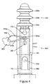
- proximal shaft 210 may include a single suture hole 240 for receiving both ends of suture thread 510, as shown in the embodiment of Figure 4 .
- Proximal shaft 210 also includes a first locking part 250 for locking collar member 120 in a manner more fully described below.
- first locking part 250 includes a flange portion 260 having a sloped proximal surface 265 and a distal locking lip 270.
- inner member 110 illustrated in Figure 2 includes flange portion 260 for locking proximal shaft 210 to collar member 120, the present invention is not intended to be limited to specific structures of first locking part 250.
- first locking part 250 need not include flange portion 260, but rather may include any structure, mechanism, or arrangement, in addition to or in lieu of flange portion 260 that is operable to lock collar member 120 to proximal shaft 210.
- Proximal shaft 210 also includes additional hole 610 configured to receive a length of actuating line 620, such as flexible, ultra-high molecular weight polyethylene suture thread (e.g., Dyneema Suture).
- Actuating line 620 may also include Kevlar, nylon, Spectra and/or any combination of these materials. Actuating line 620 may also comprise, for example, an additional length of suture thread, which may or nay not be left inside the body of the patient after insertion of the knotless suture anchor 100.
- Hole 610 may have a slightly larger diameter than that of suture holes 240a, 240b to accommodate a thicker actuating line 620.
- hole 610 may have any diameter relative to that of suture holes 240a, 240b, such as a diameter equal to or smaller than the diameter of suture holes 240a, 240b.
- the actuating line 620 is used to apply a proximal force on shaft 210 thereby relatively sliding collar member 120 distally with respect to proximal shaft 210 into a locked position, as more fully described below. It should also be appreciated, however, that proximal shaft 210 need not include hole 610 and actuating line 620 for this purpose.
- proximal force may be exerted on shaft 210 in other manners, for example, by applying a proximally directed pulling force on a suitably dimensioned tool (not shown) coupled, or engaged with, releasably or otherwise, to proximal shaft 210.
- collar member 120 includes distal and proximal ends 305, 310, an axial bore 315, two suture holes 320a, 320b respectively assigned to suture holes 240a, 240b of proximal shaft 210, and a second locking part 325.
- Axial bore 315 of collar member 120 is shaped to receive proximal shaft 210 of inner member 110.
- collar member 120 is slidably positionable into at least two positions relative to proximal shaft 210 of inner member 110: (a) an unlocked positioned, in which suture holes 320a, 320b of collar member 120 are aligned with suture holes 240a, 240b of inner member 110; and (b) a locked position, in which suture holes 320a, 320b of collar member 120 are not aligned with suture holes 240a, 240b of inner member 110.
- Second locking part 325 is configured to couple with first locking part 250 of proximal shaft 210 to axially lock collar member 120 with respect to inner member 110 when collar member 120 is placed into the locked position.
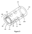
- Second locking part 325 of collar member 120 includes a slot 410, an annular flange 415 extending radially inward, and a countersink portion 420 (see Figure 1 ) formed in the distal end of annular flange 415.
- slot 410 extends proximally into a hole 411. It should be appreciated, however, that slot 410 need not include hole 411. Slot 410 and hole 411 are provided to permit flange 415 to snap over flange portion 260 of proximal shaft 210 to lock collar member 120 into the locked position.
- second locking part 325 of Figure 3 includes slot 410 and annular flange 415 for locking collar member 120 to proximal shaft 210
- the present invention described herein is not intended to be limited to specific structures of second locking part 325.
- second locking part 325 need not include slot 410 and annular flange 415, but rather may include any structure, mechanism, or arrangement, in addition to or in lieu of slot 410 and annular flange 415, operable to lock collar member 120 to proximal shaft 210.
- FIG. 5a there is seen an operational sequence for inserting knotless suture anchor 100 into tissue (e.g., bone tissue).
- tissue e.g., bone tissue.
- collar member 120 is moved with respect to proximal shaft 210 of inner member 110 into the unlocked position, such that suture holes 320a, 320b of collar member 120 are aligned with suture holes 240a, 240b of inner member 110.
- a suture leg 510a of a suture thread 510 previously threaded through tissue 950 is inserted through suture holes 240a, 320a of inner member 110 and collar member 120.
- actuating line 620 is inserted through additional hole 610 and suture anchor 100 is inserted into tissue 520 (e.g., bone tissue).
- tissue 520 e.g., bone tissue
- actuating line 620 may be previously inserted or disposed (e.g., at time of sale) through hole 610.
- Actuating line 620 is preferably made from a high strength thread, such as flexible, ultra-high molecular weight polyethylene suture thread.
- collar member 120 is relatively moved distally toward first locking part 250 of proximal shaft 210, as shown in Figure 5d .
- Collar member 120 may be relatively moved distally, for example, using a suture anchor insertion tool (not shown) configured to engage with collar member 120 for sliding collar member 120 distally with respect to proximal shaft 210. While collar member 120 is slid distally, a proximal force is exerted on both ends of actuating line 620 along direction (A) to ensure that suture anchor 100 remains stationary within tissue 520 while collar member 120 is moved distally into the locked position with respect to proximal shaft 210 of inner member 110.
- proximal force exerted on actuating line 620 may be effected by a suitably dimensioned tool (not shown) and/or a surgeon, who may grab both ends of actuating line 620 while distally moving collar member 120 into the locked position.
- the distal movement of collar member 120 causes suture holes 320a, 320b of collar member 120 to come out of alignment with suture holes 240a, 240b of inner member 110, thereby causing suture 510 to be frictionally secured between the outer surface of proximal shaft 210 and the inner surface of collar member 120, as shown in Figures 6a and 6b .
- annular flange 415 passes distal locking lip 270, annular flange 415 is forced radially inward to its original position under an inherent biasing force, as shown in Figure 5e . Once collar member 120 is placed in to the locked position, actuating line 620 may then be removed.
- collar member 120 is movable distally relative to proximal shaft 210. It is also possible to move proximal shaft 210 proximally with respect to collar member 120 to place collar member 120 into the locked position. For this purpose, a proximal force may be exerted on the ends of actuating line 620 (e.g., by a surgeon), while a suitably dimensioned tool (e.g., insertion tool 900) keeps collar member 120 stationary.
- a proximal force may be exerted on the ends of actuating line 620 (e.g., by a surgeon), while a suitably dimensioned tool (e.g., insertion tool 900) keeps collar member 120 stationary.
- Suture anchor 600 contains features similar to those of suture anchor 100, except that proximal shaft 210 and collar member 120 each include a single suture hole 240, 320, respectively, for receiving both legs 510a, 510b of suture thread 510.
- the operational sequence for inserting suture anchor 600 into tissue 520 is similar to that for inserting suture anchor 100. (See Figures 5a to 5e ).
- both legs 510a, 510b of suture thread 510 are inserted through suture holes 240, 320 of inner member 110 and collar member 120.
- the remaining steps of the operational sequence illustrated in Figures 5a to 5e are performed normally.
- Suture anchor 800 contains features similar to those of suture anchor 100, except that proximal shaft 210 of suture anchor 800 includes frangible portion 850.
- the operational sequence for inserting suture anchor 800 into tissue 520 is similar to that for inserting suture anchor 100. (See Figures 5a to 5e ). However, in this exemplary embodiment, an excess proximal force is exerted on both ends of actuating line 620, after collar member 120 is placed in to the locked position (see Figure 5e ).
- frangible portion 850 of proximal shaft 210 breaks away, and the frangible portion 850 and actuating line 620 may then be removed (note: the excess proximal force exerted on actuating line 620 is a force greater than that exerted on actuating line 620 when collar member 120 is relatively moved distally into the locked position with respect to proximal shaft 210 of inner member 110).
- a weakened portion 870, such as perforation 870, may be provided to facilitate disconnection of frangible portion 850 from proximal shaft 210.
- weakened portion 870 may be provided at other locations on proximal shaft 210 of inner member.
- weakened portion 870 may be provided distally of additional hole 610 to ensure that frangible portion 850 and suture actuating line 620 remain together while they are removed.
- weakened portion 870 may be any other type of weakening in proximal shaft 210.
- weakened portion 870 may include a notch in proximal shaft 210, which forms a portion of reduced diameter, thereby weakening proximal shaft 210 at that point.
- FIG. 8a and 8b shows an additional exemplary knotless suture anchor 1000 in unlocked and locked positions, respectively.
- Knotless suture anchor 1000 is similar to that of suture anchor 100, except that second locking part 325 of collar member 120 is located at proximal side 310 of collar member 120, and first locking part 250 of shaft 210 is located more proximally on shaft 210 than that of suture anchor 100.
- the operational sequence for inserting suture anchor 1000 into tissue 520 is similar to that for inserting suture anchor 100. (See Figures 5a to 5e ). However, to place collar member 120 into the locked position (see Figure 8b ), collar member 120 is relatively moved proximally (not distally) toward first locking part 250 of proximal shaft 210. Collar member 120 may be relatively moved distally, for example, using a suture anchor insertion tool (not shown) configured to engage with collar member 120 for pulling collar member 120 proximally with respect to proximal shaft 210.
- a distal force may be exerted on proximal shaft 210 to ensure that suture anchor 1000 remains stationary within tissue 520 while collar member 120 is moved proximally into the locked position with respect to proximal shaft 210 of inner member 110.
- the distal force exerted on the proximal shaft 210 may be effected by a suitably dimensioned tool (not shown) and/or a surgeon.
- FIG. 8b The proximal movement of collar member 120 causes suture holes 320a, 320b of collar member 120 to come out of alignment with suture holes 240a, 240b of inner member 110, thereby causing suture 510 to be frictionally secured between the outer surface of proximal shaft 210 and the inner surface of collar member 120, as shown in Figure 8b .
- Figures 8c and 8d show a cutaway view of suture anchor 1000 in the unlocked and locked positions, respectively.
Landscapes
- Health & Medical Sciences (AREA)
- Surgery (AREA)
- Life Sciences & Earth Sciences (AREA)
- Biomedical Technology (AREA)
- Nuclear Medicine, Radiotherapy & Molecular Imaging (AREA)
- Engineering & Computer Science (AREA)
- Heart & Thoracic Surgery (AREA)
- Medical Informatics (AREA)
- Molecular Biology (AREA)
- Animal Behavior & Ethology (AREA)
- General Health & Medical Sciences (AREA)
- Public Health (AREA)
- Veterinary Medicine (AREA)
- Rheumatology (AREA)
- Surgical Instruments (AREA)
Abstract
Description
- The present application is based on and claims priority to
U.S. Provisional Application No. 60/502,170 filed on September 10, 2003 - The present invention relates to suture or surgical anchors for installing same in tissue. In particular, the present invention relates to a suture anchor for anchoring a second tissue such as soft tissue to a first tissue such as bone without requiring the tying of a knot in the suture.
- It is common in the medical arts for medical personnel, such as surgeons, to use suture anchors to facilitate the attachment of soft tissue to bone while performing medical procedures. Conventionally, the bone is pre-prepared by drilling a bore hole, within which the suture anchor is subsequently inserted. A suture extending from the anchor is either attached to or threaded through the soft tissue so that the soft tissue may be secured to the bone. Once the soft tissue is secured, the surgeon must tie off or knot the suture to ensure that the soft tissue remains in place after the medical procedure. Alternatively, the suture may be attached to the tissue prior to insertion of the anchor into the bone bore hole. In this case also, a knot must be made in the suture to tie the tissue to the anchor. Often, due to tight clearances, particularly in arthroscopic surgery, it is difficult to manipulate the sutures to tie the knot.
- Document
WO 01/10312 A1 - The present invention relates to a device using a suture anchor to attach soft tissue to bone or other tissue which allows the soft tissue to be secured without tying a knot. For this purpose, a knotless suture anchor is provided for anchoring a suture thread to tissue (e.g., bone tissue). The suture anchor includes an inner member including a proximal shaft and a distal securing member shaped to secure the inner member to the tissue, the proximal shaft including a first locking part and at least one hole extending therethrough for receiving the suture thread; and a collar member including an axial bore shaped to receive the proximal shaft of the inner member, a second locking part, and at least one hole extending therethrough and assigned to the hole of the proximal shaft of the inner member, the collar member being axially slidable into unlocked and locked positions relative to the proximal shaft of the inner member, the collar member being axially relatively slidable into the locked position only to secure the suture thread. The hole of the collar member is aligned with the hole of the proximal shaft of the inner member when the collar member is placed into the unlocked position, the hole of the collar member is misaligned with the hole of the proximal shaft of the inner member when the collar member is placed into the locked position, and the first locking part of the proximal shaft engages with the second locking part of the collar member to axially lock the collar member with respect to the proximal shaft when the collar member is placed into the locked position.
- The suture is first threaded into the first tissue, forming a suture loop through the first tissue. The two legs of the suture are then inserted through the holes of the collar member and the inner member, and the anchor is inserted into the second tissue. Then, the collar member is moved distally, for example, using a suture anchor insertion tool. This causes the hole of the collar member to come out of alignment with the hole of the inner member, thereby causing the suture to be frictionally secured between the outer surface of the inner member and the inner surface of the collar member. In this manner, the suture may be fixedly secured to the anchor without need for tying a knot in the suture.
-
-
Figure 1 illustrates a first exemplary knotless suture anchor according to the present invention. -
Figure 2 illustrates an inner member of the knotless suture anchor illustrated inFigure 1 , shown rotated about its axis from the position illustrated inFigure 1 . -
Figure 3 illustrates a collar member of the knotless suture anchor illustrated inFigure 1 . -
Figure 4 illustrates another exemplary knotless suture anchor according to the present invention. -
Figures 5a to 5e show an operational sequence for inserting a knotless suture anchor into tissue. -
Figures 6a and 6b illustratively show how the knotless suture anchor secures the suture. -
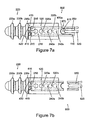
Figures 7a and 7b illustrate yet another exemplary knotless suture anchor according to the present invention. -
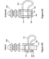
Figures 8a to 8d illustrate another exemplary suture anchor according to the present invention,Figures 8a and8c in unlocked positions, andFigures 8b and8d in locked positions. - Referring now to
Figure 1 , there is seen a first exampleknotless suture anchor 100 according to the present invention. Sutureanchor 100 includes aninner member 110 and aslidable collar member 120 configured to be concentrically disposed aboutinner member 110. Preferably,knotless suture anchor 100 is made from a bio-absorbable material. However, it should be appreciated thatknotless suture anchor 100 may be constructed from any material suitable for securingsuture anchor 100 to tissue. For example,suture anchor 100 may be constructed from a non-bioabsorbable and/or bio-compatible material.Insertion tool 900 is provided for insertingknotless suture anchor 100 into tissue and/or for securing a suture tosuture anchor 100, in a manner more fully described below. - Referring also to
Figure 2 ,inner member 110 includes aproximal shaft 210 for coupling tocollar member 120 and adistal securing member 220 for securingsuture anchor 100 intotissue 520, for example, bone tissue (seeFigures 5a to 5f ). Distal securingmember 220 may include any structure operable to secureknotless suture anchor 100 within tissue. For example, as shown inFigure 2 ,distal securing member 220 may include at least one annular rib 230 configured to engage the tissue, thereby preventingknotless suture anchor 100 from being removed after insertion. AlthoughFigure 2 illustrates distal securingmember 220 with threeannular ribs member 220 may include any number of annular ribs 230 for securingsuture anchor 100 to tissue. It should also be appreciated that distal securingmember 220 may include other structures in addition to or in lieu of annular rib 230 for engaging tissue. For example, distal securingmember 220 may include at least one barb (not shown) for securingknotless suture anchor 100 into tissue. Distal securingmember 220 may also include, for example, at least one suitably dimensioned flange portion (not shown), at least one raised portion (not shown), at least one hooked portion (not shown), or any other structure operable to securesuture anchor 100 to tissue. -
Proximal shaft 210 includes twosuture holes Figures 5a to 5e ). AlthoughFigure 2 illustratessuture holes proximal shaft 210 at a right angle toaxis 242 ofproximal shaft 210, it should be appreciated thatsuture holes proximal shaft 210 at any suitable angle with respect to the axis ofproximal shaft 210. It should also be appreciated thatproximal shaft 210 may include any number ofsuture holes 240 for receiving any number ofsuture threads 510. For example,proximal shaft 210 may include asingle suture hole 240 for receiving both ends ofsuture thread 510, as shown in the embodiment ofFigure 4 . -
Proximal shaft 210 also includes afirst locking part 250 forlocking collar member 120 in a manner more fully described below. In the embodiment illustrated inFigure 2 ,first locking part 250 includes aflange portion 260 having a slopedproximal surface 265 and adistal locking lip 270. Althoughinner member 110 illustrated inFigure 2 includesflange portion 260 for lockingproximal shaft 210 tocollar member 120, the present invention is not intended to be limited to specific structures offirst locking part 250. In this regard, it should be appreciated that first lockingpart 250 need not includeflange portion 260, but rather may include any structure, mechanism, or arrangement, in addition to or in lieu offlange portion 260 that is operable to lockcollar member 120 toproximal shaft 210. -
Proximal shaft 210 also includesadditional hole 610 configured to receive a length of actuatingline 620, such as flexible, ultra-high molecular weight polyethylene suture thread (e.g., Dyneema Suture). Actuatingline 620 may also include Kevlar, nylon, Spectra and/or any combination of these materials. Actuatingline 620 may also comprise, for example, an additional length of suture thread, which may or nay not be left inside the body of the patient after insertion of theknotless suture anchor 100.Hole 610 may have a slightly larger diameter than that ofsuture holes thicker actuating line 620. However, it should be appreciated thathole 610 may have any diameter relative to that ofsuture holes suture holes line 620 is used to apply a proximal force onshaft 210 thereby relatively slidingcollar member 120 distally with respect toproximal shaft 210 into a locked position, as more fully described below. It should also be appreciated, however, thatproximal shaft 210 need not includehole 610 and actuatingline 620 for this purpose. Instead, proximal force may be exerted onshaft 210 in other manners, for example, by applying a proximally directed pulling force on a suitably dimensioned tool (not shown) coupled, or engaged with, releasably or otherwise, toproximal shaft 210. - Referring to
Figure 3 ,collar member 120 includes distal andproximal ends axial bore 315, twosuture holes suture holes proximal shaft 210, and asecond locking part 325.Axial bore 315 ofcollar member 120 is shaped to receiveproximal shaft 210 ofinner member 110. In this manner,collar member 120 is slidably positionable into at least two positions relative toproximal shaft 210 of inner member 110: (a) an unlocked positioned, in whichsuture holes collar member 120 are aligned withsuture holes inner member 110; and (b) a locked position, in whichsuture holes collar member 120 are not aligned withsuture holes inner member 110. Second lockingpart 325 is configured to couple withfirst locking part 250 ofproximal shaft 210 to axiallylock collar member 120 with respect toinner member 110 whencollar member 120 is placed into the locked position. Second lockingpart 325 ofcollar member 120 includes aslot 410, anannular flange 415 extending radially inward, and a countersink portion 420 (seeFigure 1 ) formed in the distal end ofannular flange 415. As shown inFigure 3 ,slot 410 extends proximally into ahole 411. It should be appreciated, however, thatslot 410 need not includehole 411.Slot 410 andhole 411 are provided to permitflange 415 to snap overflange portion 260 ofproximal shaft 210 to lockcollar member 120 into the locked position. Furthermore, althoughsecond locking part 325 ofFigure 3 includesslot 410 andannular flange 415 for lockingcollar member 120 toproximal shaft 210, the present invention described herein is not intended to be limited to specific structures ofsecond locking part 325. In this regard, it should be appreciated that second lockingpart 325 need not includeslot 410 andannular flange 415, but rather may include any structure, mechanism, or arrangement, in addition to or in lieu ofslot 410 andannular flange 415, operable to lockcollar member 120 toproximal shaft 210. - Referring now to
Figures 5a to 5e , there is seen an operational sequence for insertingknotless suture anchor 100 into tissue (e.g., bone tissue). First, as shown inFigure 5a ,collar member 120 is moved with respect toproximal shaft 210 ofinner member 110 into the unlocked position, such thatsuture holes collar member 120 are aligned withsuture holes inner member 110. Then, as shown inFigure 5b , asuture leg 510a of asuture thread 510 previously threaded throughtissue 950 is inserted throughsuture holes inner member 110 andcollar member 120. Theother leg 510b ofsuture thread 510 is inserted throughsuture holes inner member 110 andcollar member 120. Next, as shown inFigure 5c , actuatingline 620 is inserted throughadditional hole 610 andsuture anchor 100 is inserted into tissue 520 (e.g., bone tissue). Alternatively, actuatingline 620 may be previously inserted or disposed (e.g., at time of sale) throughhole 610.Actuating line 620 is preferably made from a high strength thread, such as flexible, ultra-high molecular weight polyethylene suture thread. Oncesuture anchor 100 is inserted withintissue 520, distal securingmember 220 engagestissue 520 to securesuture anchor 100 in place withintissue 520. Then,collar member 120 is relatively moved distally toward first lockingpart 250 ofproximal shaft 210, as shown inFigure 5d .Collar member 120 may be relatively moved distally, for example, using a suture anchor insertion tool (not shown) configured to engage withcollar member 120 for slidingcollar member 120 distally with respect toproximal shaft 210. Whilecollar member 120 is slid distally, a proximal force is exerted on both ends of actuatingline 620 along direction (A) to ensure thatsuture anchor 100 remains stationary withintissue 520 whilecollar member 120 is moved distally into the locked position with respect toproximal shaft 210 ofinner member 110. The proximal force exerted on actuatingline 620 may be effected by a suitably dimensioned tool (not shown) and/or a surgeon, who may grab both ends of actuatingline 620 while distally movingcollar member 120 into the locked position. The distal movement ofcollar member 120 causessuture holes collar member 120 to come out of alignment withsuture holes inner member 110, thereby causingsuture 510 to be frictionally secured between the outer surface ofproximal shaft 210 and the inner surface ofcollar member 120, as shown inFigures 6a and 6b . Ascollar member 120 is further displaced distally,countersink portion 420 ofannular flange 415 engages slopedproximal surface 265 offlange portion 260 ofproximal shaft 210, thereby causingannular flange 415 to extend radially outward fromproximal shaft 210, as shown inFigure 5d (Slot 410 is provided to help facilitate the radial extension of annular flange 415). To placecollar member 120 into the locked position with respect toproximal shaft 210,collar member 120 is further displaced distally with respect toproximal shaft 210 untilannular flange 415 passesdistal locking lip 270 offirst locking part 250. Afterannular flange 415 passesdistal locking lip 270,annular flange 415 is forced radially inward to its original position under an inherent biasing force, as shown inFigure 5e . Oncecollar member 120 is placed in to the locked position, actuatingline 620 may then be removed. - It should be appreciated that
collar member 120 is movable distally relative toproximal shaft 210. It is also possible to moveproximal shaft 210 proximally with respect tocollar member 120 to placecollar member 120 into the locked position. For this purpose, a proximal force may be exerted on the ends of actuating line 620 (e.g., by a surgeon), while a suitably dimensioned tool (e.g., insertion tool 900) keepscollar member 120 stationary. - Referring now to
Figure 4 , there is seen anotherexemplary suture anchor 600 according to the present invention.Suture anchor 600 contains features similar to those ofsuture anchor 100, except thatproximal shaft 210 andcollar member 120 each include asingle suture hole 240, 320, respectively, for receiving bothlegs suture thread 510. The operational sequence for insertingsuture anchor 600 intotissue 520 is similar to that for insertingsuture anchor 100. (SeeFigures 5a to 5e ). When insertingsuture anchor 600, however, after being threaded throughtissue 950, bothlegs suture thread 510 are inserted throughsuture holes 240, 320 ofinner member 110 andcollar member 120. The remaining steps of the operational sequence illustrated inFigures 5a to 5e are performed normally. - Referring now to
Figure 7a and 7b , there is seen yet anotherexemplary suture anchor 800 according to the present invention.Suture anchor 800 contains features similar to those ofsuture anchor 100, except thatproximal shaft 210 ofsuture anchor 800 includesfrangible portion 850. The operational sequence for insertingsuture anchor 800 intotissue 520 is similar to that for insertingsuture anchor 100. (SeeFigures 5a to 5e ). However, in this exemplary embodiment, an excess proximal force is exerted on both ends of actuatingline 620, aftercollar member 120 is placed in to the locked position (seeFigure 5e ). The excess force causesfrangible portion 850 ofproximal shaft 210 to break away, and thefrangible portion 850 andactuating line 620 may then be removed (note: the excess proximal force exerted on actuatingline 620 is a force greater than that exerted on actuatingline 620 whencollar member 120 is relatively moved distally into the locked position with respect toproximal shaft 210 of inner member 110). A weakenedportion 870, such asperforation 870, may be provided to facilitate disconnection offrangible portion 850 fromproximal shaft 210. AlthoughFigures 7a and 7b show weakenedportion 870 extending throughadditional hole 610, it should be appreciated that the weakenedportion 870 may be provided at other locations onproximal shaft 210 of inner member. For example, weakenedportion 870 may be provided distally ofadditional hole 610 to ensure thatfrangible portion 850 andsuture actuating line 620 remain together while they are removed. Alternatively, weakenedportion 870 may be any other type of weakening inproximal shaft 210. For example, weakenedportion 870 may include a notch inproximal shaft 210, which forms a portion of reduced diameter, thereby weakeningproximal shaft 210 at that point. -
Figures 8a and 8b shows an additional exemplaryknotless suture anchor 1000 in unlocked and locked positions, respectively.Knotless suture anchor 1000 is similar to that ofsuture anchor 100, except thatsecond locking part 325 ofcollar member 120 is located atproximal side 310 ofcollar member 120, and first lockingpart 250 ofshaft 210 is located more proximally onshaft 210 than that ofsuture anchor 100. - The operational sequence for inserting
suture anchor 1000 intotissue 520 is similar to that for insertingsuture anchor 100. (SeeFigures 5a to 5e ). However, to placecollar member 120 into the locked position (seeFigure 8b ),collar member 120 is relatively moved proximally (not distally) toward first lockingpart 250 ofproximal shaft 210.Collar member 120 may be relatively moved distally, for example, using a suture anchor insertion tool (not shown) configured to engage withcollar member 120 for pullingcollar member 120 proximally with respect toproximal shaft 210. Whilecollar member 120 is slid proximally, a distal force may be exerted onproximal shaft 210 to ensure thatsuture anchor 1000 remains stationary withintissue 520 whilecollar member 120 is moved proximally into the locked position with respect toproximal shaft 210 ofinner member 110. The distal force exerted on theproximal shaft 210 may be effected by a suitably dimensioned tool (not shown) and/or a surgeon. The proximal movement ofcollar member 120 causessuture holes collar member 120 to come out of alignment withsuture holes inner member 110, thereby causingsuture 510 to be frictionally secured between the outer surface ofproximal shaft 210 and the inner surface ofcollar member 120, as shown inFigure 8b .Figures 8c and 8d show a cutaway view ofsuture anchor 1000 in the unlocked and locked positions, respectively. - Although the present invention has been described in relation to particular embodiments thereof, many other variations and modifications and other uses will become apparent to those skilled in the art. Therefore, the present invention should be limited not by the specific disclosure herein, but only by the appended claims.
Claims (12)
- A knotless suture anchor (100, 600, 800, 1000) for anchoring a suture thread (510) to tissue (520), comprising:an inner member (110) including a proximal shaft (210) and a distal securing member (220),
the proximal shaft including a first locking part (250) and at least one hole (240) extending therethrough for receiving the suture thread; anda collar member (120) including an axial bore (315) shaped to receive the proximal shaft of the inner member and second locking part (325),characterized in that :said distal securing member (220) is shaped to secure the inner member to the tissue and said collar member includes at least one hole (320) extending therethrough and assigned to the hole of the proximal shaft of the inner member, the collar member being axially slidable into unlocked and locked positions relative to the proximal shaft of the inner member, the collar member being relatively axially slidable into the locked position only to secure the suture thread;wherein the hole of the collar member is aligned with the hole of the proximal shaft of the inner member when the collar member is placed into the unlocked position, the hole of the collar member is misaligned with the hole of the proximal shaft of the inner member when the collar member is placed into the locked position, and the first locking part of the proximal shaft engages with the second locking part of the collar member to axially lock the collar member with respect to the proximal shaft when the collar member is placed into the locked position. - The knotless suture anchor of claim 1, wherein the distal securing member includes at least one annular rib (230).
- The knotless suture anchor of claim 1, wherein the first locking part of the proximal shaft includes a flange portion (260) having a sloped proximal surface (265) and a distal locking lip (270), and the second locking part of the collar member includes a transverse slot, an annular flange extending radially inward, and a countersink portion formed in a distal end of the annular flange.
- The knotless suture anchor of claim 1, wherein the proximal shaft of the inner member includes an additional hole (610) for receiving an actuating line.
- The knotless suture anchor of claim 4, wherein the actuating line (620) includes at least one material selected from the group consisting of ultra-high molecular weight polyethylene, Kevlar and Spectra.
- The knotless suture anchor of claim 4, wherein the actuating line is an additional length of suture thread.
- The knotless suture anchor of claim 4, wherein the proximal shaft of the inner member includes a frangible portion (850) configured to disconnect at least a portion of the proximal shaft when an excess proximal force is exerted on the actuating line.
- The knotless suture anchor of claim 1, wherein the proximal shaft of the inner member includes two holes, and the collar member includes two holes assigned to the holes of the proximal shaft, the holes of the proximal shaft and the collar member being shaped to receive respective ends of the suture thread when the collar member is placed into the unlocked position with respect to the proximal shaft of the inner member.
- The knotless suture anchor of claim 8, wherein the proximal shaft of the inner member includes an additional hole for receiving an actuating line.
- The knotless suture anchor of claim 9, wherein the actuating line comprises a length of ultra-high molecular weight polyethylene suture thread.
- The knotless suture anchor of claim 9, wherein the proximal shaft of the inner member includes a frangible portion configured to disconnect at least a portion of the proximal shaft when an excess proximal force is exerted on the actuating line.
- The knotless suture anchor of claim 1, wherein the suture anchor is bio-absorbable.
Applications Claiming Priority (3)
| Application Number | Priority Date | Filing Date | Title |
|---|---|---|---|
| US50217003P | 2003-09-10 | 2003-09-10 | |
| US10/937,592 US7837710B2 (en) | 2003-09-10 | 2004-09-09 | Knotless suture anchor |
| PCT/US2004/029377 WO2005037112A1 (en) | 2003-09-10 | 2004-09-10 | Knotless suture anchor new |
Publications (3)
| Publication Number | Publication Date |
|---|---|
| EP1663015A1 EP1663015A1 (en) | 2006-06-07 |
| EP1663015A4 EP1663015A4 (en) | 2010-05-05 |
| EP1663015B1 true EP1663015B1 (en) | 2011-02-23 |
Family
ID=34228904
Family Applications (1)
| Application Number | Title | Priority Date | Filing Date |
|---|---|---|---|
| EP04783579A Expired - Lifetime EP1663015B1 (en) | 2003-09-10 | 2004-09-10 | Knotless suture anchor new |
Country Status (6)
| Country | Link |
|---|---|
| US (1) | US7837710B2 (en) |
| EP (1) | EP1663015B1 (en) |
| AU (1) | AU2004281635B2 (en) |
| CA (1) | CA2538700C (en) |
| DE (1) | DE602004031536D1 (en) |
| WO (1) | WO2005037112A1 (en) |
Families Citing this family (140)
| Publication number | Priority date | Publication date | Assignee | Title |
|---|---|---|---|---|
| US6319252B1 (en) * | 1999-07-23 | 2001-11-20 | Mcdevitt Dennis | System and method for attaching soft tissue to bone |
| US6527794B1 (en) | 1999-08-10 | 2003-03-04 | Ethicon, Inc. | Self-locking suture anchor |
| US6733506B1 (en) | 2000-11-16 | 2004-05-11 | Ethicon, Inc. | Apparatus and method for attaching soft tissue to bone |
| US6770076B2 (en) * | 2001-02-12 | 2004-08-03 | Opus Medical, Inc. | Method and apparatus for attaching connective tissues to bone using a knotless suture anchoring device |
| US8641727B2 (en) | 2002-06-13 | 2014-02-04 | Guided Delivery Systems, Inc. | Devices and methods for heart valve repair |
| EP1530441B1 (en) * | 2002-06-13 | 2017-08-02 | Ancora Heart, Inc. | Devices and methods for heart valve repair |
| US7753858B2 (en) * | 2002-06-13 | 2010-07-13 | Guided Delivery Systems, Inc. | Delivery devices and methods for heart valve repair |
| US7666193B2 (en) * | 2002-06-13 | 2010-02-23 | Guided Delivery Sytems, Inc. | Delivery devices and methods for heart valve repair |
| US8287555B2 (en) * | 2003-02-06 | 2012-10-16 | Guided Delivery Systems, Inc. | Devices and methods for heart valve repair |
| US7588582B2 (en) * | 2002-06-13 | 2009-09-15 | Guided Delivery Systems Inc. | Methods for remodeling cardiac tissue |
| US20050216078A1 (en) * | 2002-06-13 | 2005-09-29 | Guided Delivery Systems, Inc. | Delivery devices and methods for heart valve repair |
| US7758637B2 (en) * | 2003-02-06 | 2010-07-20 | Guided Delivery Systems, Inc. | Delivery devices and methods for heart valve repair |
| US20060241656A1 (en) * | 2002-06-13 | 2006-10-26 | Starksen Niel F | Delivery devices and methods for heart valve repair |
| US7753924B2 (en) * | 2003-09-04 | 2010-07-13 | Guided Delivery Systems, Inc. | Delivery devices and methods for heart valve repair |
| US7753922B2 (en) * | 2003-09-04 | 2010-07-13 | Guided Delivery Systems, Inc. | Devices and methods for cardiac annulus stabilization and treatment |
| US7883538B2 (en) * | 2002-06-13 | 2011-02-08 | Guided Delivery Systems Inc. | Methods and devices for termination |
| US20040243227A1 (en) * | 2002-06-13 | 2004-12-02 | Guided Delivery Systems, Inc. | Delivery devices and methods for heart valve repair |
| US20060122633A1 (en) * | 2002-06-13 | 2006-06-08 | John To | Methods and devices for termination |
| US9949829B2 (en) | 2002-06-13 | 2018-04-24 | Ancora Heart, Inc. | Delivery devices and methods for heart valve repair |
| US7534204B2 (en) * | 2003-09-03 | 2009-05-19 | Guided Delivery Systems, Inc. | Cardiac visualization devices and methods |
| US20050273138A1 (en) * | 2003-12-19 | 2005-12-08 | Guided Delivery Systems, Inc. | Devices and methods for anchoring tissue |
| US20050245932A1 (en) * | 2004-04-16 | 2005-11-03 | Fanton Gary S | Apparatus and methods for securing tissue to bone |
| US7585311B2 (en) | 2004-06-02 | 2009-09-08 | Kfx Medical Corporation | System and method for attaching soft tissue to bone |
| US8062334B2 (en) | 2004-06-02 | 2011-11-22 | Kfx Medical Corporation | Suture anchor |
| US20070055206A1 (en) * | 2005-08-10 | 2007-03-08 | Guided Delivery Systems, Inc. | Methods and devices for deployment of tissue anchors |
| US20070112385A1 (en) * | 2005-11-15 | 2007-05-17 | Conlon Sean P | Expandable suture anchor |
| FR2893836B1 (en) * | 2005-11-29 | 2008-10-10 | Pierre Imbert | SURGICAL IMPLANT WITH EXTRA CORTICAL SUPPORT FOR LIGAMENTARY TRANSPLANT |
| US20070167950A1 (en) * | 2005-12-22 | 2007-07-19 | Tauro Joseph C | System and method for attaching soft tissue to bone |
| DE102006010116A1 (en) * | 2006-02-27 | 2007-08-30 | Karl Storz Gmbh & Co.Kg | Anchor element for knot-free fixation of tissue to a bone |
| US20070276437A1 (en) * | 2006-05-25 | 2007-11-29 | Mitralign, Inc. | Lockers for surgical tensioning members and methods of using the same to secure surgical tensioning members |
| US20080009900A1 (en) * | 2006-06-12 | 2008-01-10 | Kfx Medical Corporation | Surgical grasping device |
| US8202295B2 (en) | 2006-07-20 | 2012-06-19 | Kaplan Lee D | Surgical instruments |
| JP5323694B2 (en) * | 2006-07-20 | 2013-10-23 | リー ディー カプラン | Surgical instruments |
| US12533121B2 (en) | 2006-07-20 | 2026-01-27 | Lee D. Kaplan | Surgical instruments |
| US8133258B2 (en) * | 2006-08-03 | 2012-03-13 | Arthrocare Corporation | Method and apparatus for attaching connective tissues to bone using a knotless suture anchoring device |
| US9750492B2 (en) * | 2006-08-04 | 2017-09-05 | Depuy Mitek, Llc | Suture anchor system with tension relief mechanism |
| US9788825B2 (en) * | 2006-08-04 | 2017-10-17 | Depuy Mitek, Llc | Suture anchor with relief mechanism |
| EP2047813A1 (en) * | 2007-10-11 | 2009-04-15 | Abbott Spine | Bone fixing system and method of use |
| US7674276B2 (en) * | 2006-10-06 | 2010-03-09 | Biomet Sports Medicine, Llc | Rotational securing of a suture |
| US20100179573A1 (en) * | 2006-10-31 | 2010-07-15 | Core Essence Orthopaedics, Llc | Medical device and procedure for attaching tissue to bone |
| US8414613B2 (en) * | 2006-10-31 | 2013-04-09 | Orthonoble Inc. | Medical device and procedure for attaching tissue to bone |
| US20080177380A1 (en) * | 2007-01-19 | 2008-07-24 | Starksen Niel F | Methods and devices for heart tissue repair |
| US8137381B2 (en) * | 2007-04-25 | 2012-03-20 | Arthrocare Corporation | Knotless suture anchor having discrete polymer components and related methods |
| US9861354B2 (en) | 2011-05-06 | 2018-01-09 | Ceterix Orthopaedics, Inc. | Meniscus repair |
| US8663253B2 (en) | 2007-07-03 | 2014-03-04 | Ceterix Orthopaedics, Inc. | Methods of meniscus repair |
| US8500809B2 (en) | 2011-01-10 | 2013-08-06 | Ceterix Orthopaedics, Inc. | Implant and method for repair of the anterior cruciate ligament |
| US8465505B2 (en) | 2011-05-06 | 2013-06-18 | Ceterix Orthopaedics, Inc. | Suture passer devices and methods |
| US8702731B2 (en) | 2007-07-03 | 2014-04-22 | Ceterix Orthopaedics, Inc. | Suturing and repairing tissue using in vivo suture loading |
| WO2009026078A2 (en) * | 2007-08-17 | 2009-02-26 | Wilson-Cook Medical, Inc. | Suture lock |
| US7963972B2 (en) | 2007-09-12 | 2011-06-21 | Arthrocare Corporation | Implant and delivery system for soft tissue repair |
| JP5341901B2 (en) | 2007-10-25 | 2013-11-13 | スミス アンド ネフュー インコーポレーテッド | Anchor assembly |
| WO2014189605A1 (en) | 2013-03-15 | 2014-11-27 | Mark Brunsvold | Suture anchor |
| US9277909B2 (en) * | 2007-10-27 | 2016-03-08 | Parcus Medical, Llc | Suture anchor |
| WO2009061504A1 (en) | 2007-11-05 | 2009-05-14 | Revolutionary Surgical Device, Llc | Suture passing instrument and method |
| KR100922127B1 (en) | 2007-12-21 | 2009-10-16 | 서보건 | Suture fixtures for fixing the sutures sutured to the intervertebral discs within the vertebrae |
| US9295460B2 (en) * | 2007-12-31 | 2016-03-29 | Cayenne Medical, Inc. | Anchors and method for securing suture to bone |
| JP2011510797A (en) * | 2008-02-06 | 2011-04-07 | ガイデッド デリバリー システムズ, インコーポレイテッド | Multiple window guide tunnel |
| US9131939B1 (en) | 2008-02-27 | 2015-09-15 | Mitralign, Inc. | Device for percutaneously delivering a cardiac implant through the application of direct actuation forces external to the body |
| US8409252B2 (en) * | 2008-03-25 | 2013-04-02 | Linvatec Corporation | Knotless suture anchor |
| US8162978B2 (en) * | 2008-03-25 | 2012-04-24 | Linvatec Corporation | Non-metallic knotless suture anchor |
| EP3431013B1 (en) | 2008-06-16 | 2026-05-06 | Cayenne Medical, Inc. | Anchoring system for securing suture to bone |
| US8709040B2 (en) | 2008-06-26 | 2014-04-29 | Vitasynergies, Llc | Suture anchor, guide for locating a hole in a bone, and suture anchor delivery tool |
| JP5698130B2 (en) * | 2008-07-17 | 2015-04-08 | スミス アンド ネフュー インコーポレーテッドSmith & Nephew,Inc. | Surgical device |
| US8936620B2 (en) * | 2008-07-21 | 2015-01-20 | Pivot Medical, Inc. | Method and apparatus for securing soft tissue to bone |
| US20110190815A1 (en) * | 2008-09-08 | 2011-08-04 | Saliman Justin D | Knotless suture anchors |
| KR20110084911A (en) | 2008-10-10 | 2011-07-26 | 가이디드 딜리버리 시스템즈 인코퍼레이티드 | Termination device and related method |
| WO2010042857A1 (en) | 2008-10-10 | 2010-04-15 | Guided Delivery Systems Inc. | Tether tensioning devices and related methods |
| WO2010062379A1 (en) * | 2008-11-25 | 2010-06-03 | Sonoma Orthopedic Products, Inc. | Bone fracture fixation screws, systems and methods of use |
| WO2010085456A1 (en) | 2009-01-20 | 2010-07-29 | Guided Delivery Systems Inc. | Anchor deployment devices and related methods |
| WO2010085869A1 (en) * | 2009-01-30 | 2010-08-05 | Fayez Almodhen | Laparoscopic tool and method for a laparoscopic surgery |
| US8585578B2 (en) * | 2009-02-05 | 2013-11-19 | Coloplast A/S | Implantable devices, tools and methods for anatomical support |
| US8720446B2 (en) | 2010-06-04 | 2014-05-13 | Coloplast A/S | Sacrocolpopexy support and method of implantation |
| US8585579B2 (en) * | 2009-02-05 | 2013-11-19 | Coloplast A/S | Implantable anatomical support |
| US11219515B2 (en) | 2009-02-05 | 2022-01-11 | Coloplast A/S | Incontinence treatment device having a first anchor assembly and a second anchor assembly |
| US8696544B2 (en) | 2009-02-05 | 2014-04-15 | Coloplast A/S | Minimally invasive adjustable support |
| WO2010138946A1 (en) * | 2009-05-29 | 2010-12-02 | Orizon Llc | Suture anchor |
| DK200900718A (en) * | 2009-06-08 | 2010-12-09 | Coloplast As | Anatomical augmentation device |
| US11246585B2 (en) | 2009-07-17 | 2022-02-15 | Stryker Puerto Rico Limited | Method and apparatus for attaching tissue to bone, including the provision and use of a novel knotless suture anchor system |
| US10238379B2 (en) | 2009-07-17 | 2019-03-26 | Pivot Medical, Inc. | Method and apparatus for attaching tissue to bone, including the provision and use of a novel knotless suture anchor system |
| US10426456B2 (en) | 2009-07-17 | 2019-10-01 | Pivot Medical, Inc. | Method and apparatus for re-attaching the labrum to the acetabulum, including the provision and use of a novel suture anchor system |
| US10058319B2 (en) | 2009-07-17 | 2018-08-28 | Pivot Medical, Inc. | Method and apparatus for attaching tissue to bone, including the provision and use of a novel knotless suture anchor system, including a novel locking element |
| US9179905B2 (en) | 2009-07-17 | 2015-11-10 | Pivot Medical, Inc. | Method and apparatus for re-attaching the labrum to the acetabulum, including the provision and use of a novel suture anchor system |
| US10136884B2 (en) | 2009-07-17 | 2018-11-27 | Pivot Medical, Inc. | Method and apparatus for attaching tissue to bone, including the provision and use of a novel knotless suture anchor system, including a retractable sheath |
| US9149268B2 (en) | 2009-07-17 | 2015-10-06 | Pivot Medical, Inc. | Method and apparatus for attaching tissue to bone, including the provision and use of a novel knotless suture anchor system |
| US12232718B2 (en) | 2009-07-17 | 2025-02-25 | Stryker Puerto Rico Limited | Method and apparatus for attaching tissue to bone, including the provision and use of a novel knotless suture anchor system |
| US12446871B2 (en) | 2009-07-17 | 2025-10-21 | Stryker Puerto Rico, LLC | Method and apparatus for attaching tissue to bone, including the provision and use of a novel knotless suture anchor system |
| US11197663B2 (en) | 2009-07-17 | 2021-12-14 | Stryker Puerto Rico Limited | Method and apparatus for attaching tissue to bone, including the provision and use of a novel knotless suture anchor system |
| US8226685B2 (en) * | 2009-08-25 | 2012-07-24 | Redline Orthopedic Innovations, Llc | Suture anchor and method of use |
| WO2011057245A2 (en) | 2009-11-09 | 2011-05-12 | Suturepro Technologies, Inc. | Devices, systems and methods for meniscus repair |
| EP2498686B1 (en) * | 2009-11-10 | 2024-01-10 | Smith & Nephew, Inc. | Tissue repair devices |
| US9314240B2 (en) | 2009-11-10 | 2016-04-19 | Smith & Nephew, Inc. | Locking suture anchor assembly |
| US9113859B2 (en) * | 2009-11-16 | 2015-08-25 | Arthrex, Inc. | Suture anchor eyelet with suture loader |
| WO2012031204A2 (en) | 2010-09-03 | 2012-03-08 | Guided Delivery Systems Inc. | Devices and methods for anchoring tissue |
| US20120065648A1 (en) * | 2010-09-10 | 2012-03-15 | Abbott Cardiovascular Systems, Inc. | Suture closure device |
| US9011490B2 (en) | 2011-03-03 | 2015-04-21 | Cook Medical Technologies, LLC | Suture retention device |
| WO2013003746A1 (en) | 2011-06-29 | 2013-01-03 | Pivot Medical, Inc. | Method and apparatus for re-attaching the labrum to the acetabulum, including the provision and use of a novel suture anchor system |
| US9636101B2 (en) | 2011-09-01 | 2017-05-02 | Arthrocare Corporation | Bone anchor having an integrated stress isolator |
| US8764798B2 (en) | 2011-10-03 | 2014-07-01 | Smith & Nephew, Inc. | Knotless suture anchor |
| US9782165B2 (en) | 2011-11-11 | 2017-10-10 | VentureMD Innovations, LLC | Transosseous attachment |
| EP2775937B1 (en) * | 2011-11-11 | 2016-07-20 | Venture MD | Transosseous attachment anchor |
| US10675014B2 (en) | 2011-11-16 | 2020-06-09 | Crossroads Extremity Systems, Llc | Knotless soft tissue attachment |
| US10548585B2 (en) | 2011-11-16 | 2020-02-04 | VentureMD Innovations, LLC | Soft tissue attachment |
| US10470756B2 (en) | 2011-11-16 | 2019-11-12 | VentureMD Innovations, LLC | Suture anchor and method |
| US9131937B2 (en) * | 2011-11-16 | 2015-09-15 | VentureMD Innovations, LLC | Suture anchor |
| US9113868B2 (en) | 2011-12-15 | 2015-08-25 | Ethicon Endo-Surgery, Inc. | Devices and methods for endoluminal plication |
| US9173657B2 (en) | 2011-12-15 | 2015-11-03 | Ethicon Endo-Surgery, Inc. | Devices and methods for endoluminal plication |
| US8956361B2 (en) | 2011-12-19 | 2015-02-17 | Amendia, Inc. | Extended tab bone screw system |
| US9023083B2 (en) | 2012-01-27 | 2015-05-05 | Arthrocare Corporation | Method for soft tissue repair with free floating suture locking member |
| US9364210B2 (en) | 2012-01-27 | 2016-06-14 | Arthrocare Corporation | Biased wedge suture anchor and method for soft tissue repair |
| US9226742B2 (en) | 2012-01-27 | 2016-01-05 | Arthrocare Corporation | Restricted wedge suture anchor and method for soft tissue repair |
| US9034014B2 (en) | 2012-01-27 | 2015-05-19 | Arthrocare Corporation | Free floating wedge suture anchor for soft tissue repair |
| US9198649B2 (en) | 2012-01-27 | 2015-12-01 | Arthrocare Corporation | Rotating locking member suture anchor and method for soft tissue repair |
| US9107655B2 (en) | 2012-02-16 | 2015-08-18 | Cook Medical Technologies Llc | External suture securement devices and methods |
| US8992547B2 (en) | 2012-03-21 | 2015-03-31 | Ethicon Endo-Surgery, Inc. | Methods and devices for creating tissue plications |
| US9855028B2 (en) | 2012-04-06 | 2018-01-02 | Arthrocare Corporation | Multi-suture knotless anchor for attaching tissue to bone and related method |
| US9138221B2 (en) * | 2012-09-20 | 2015-09-22 | Medos International Sarl | Anti-backup suture anchor |
| US9687221B2 (en) | 2013-02-13 | 2017-06-27 | Venture MD Innovations, LLC | Method of anchoring a suture |
| WO2014176270A1 (en) | 2013-04-22 | 2014-10-30 | Pivot Medical, Inc. | Method and apparatus for attaching tissue to bone |
| US9936940B2 (en) | 2013-06-07 | 2018-04-10 | Biomet Sports Medicine, Llc | Method and apparatus for coupling soft tissue to bone |
| US9572563B2 (en) * | 2013-07-08 | 2017-02-21 | Biomet Sports Medicine, LLC. | Suture anchor and related method |
| WO2015089397A1 (en) | 2013-12-12 | 2015-06-18 | Pivot Medical, Inc. | Method and apparatus for attaching tissue to bone, including the provision and use of a novel knotless suture anchor system |
| US10245017B2 (en) | 2014-05-30 | 2019-04-02 | Biomet Manufacturing, Llc | Knotless twist suture anchor |
| WO2016141358A1 (en) | 2015-03-05 | 2016-09-09 | Guided Delivery Systems Inc. | Devices and methods of visualizing and determining depth of penetration in cardiac tissue |
| EP3294218B1 (en) | 2015-05-12 | 2022-02-09 | Ancora Heart, Inc. | Device for releasing catheters from cardiac structures |
| US9962174B2 (en) | 2015-07-17 | 2018-05-08 | Kator, Llc | Transosseous method |
| US10154868B2 (en) | 2015-07-17 | 2018-12-18 | Kator, Llc | Transosseous method |
| US10820918B2 (en) | 2015-07-17 | 2020-11-03 | Crossroads Extremity Systems, Llc | Transosseous guide and method |
| US12383253B2 (en) | 2015-08-04 | 2025-08-12 | Crossroads Extremity Systems, Llc | Suture anchor |
| US10226243B2 (en) | 2015-08-04 | 2019-03-12 | Kator, Llc | Transosseous suture anchor |
| US9924935B2 (en) | 2015-10-23 | 2018-03-27 | Smith & Nephew, Inc. | Suture anchor assembly with slip fit tip |
| CN116746975A (en) | 2016-11-18 | 2023-09-15 | 复心公司 | Myocardial implant load sharing devices and methods for promoting LV function |
| US10993710B2 (en) * | 2016-12-21 | 2021-05-04 | Wright Medical Technology, Inc. | Syndesmosis construct |
| ES2919274T3 (en) | 2017-01-16 | 2022-07-22 | Coloplast As | sacrocolpopexy support |
| KR101959783B1 (en) * | 2017-03-29 | 2019-03-19 | 주식회사 티제이씨라이프 | Suture Anchor Having Locking Structure, and Suture Anchor Kit Having the Same |
| US10575843B2 (en) * | 2018-01-17 | 2020-03-03 | Ring Orthopedics, Inc. | Knotless suture anchor |
| WO2019169386A1 (en) * | 2018-03-02 | 2019-09-06 | Syntorr, Inc. | Far cortex intraosseous suture anchor |
| WO2021011659A1 (en) | 2019-07-15 | 2021-01-21 | Ancora Heart, Inc. | Devices and methods for tether cutting |
| US12161318B2 (en) * | 2020-12-01 | 2024-12-10 | Dunamis Medical Technologies, Llc | Re-tensionable suture anchor system and related methods |
| KR102752999B1 (en) * | 2022-10-14 | 2025-01-09 | 가톨릭대학교 산학협력단 | A simple suture anchor |
| US20250072884A1 (en) * | 2023-09-05 | 2025-03-06 | Biomet Manufacturing, Llc | Lateral row anchor |
Family Cites Families (17)
| Publication number | Priority date | Publication date | Assignee | Title |
|---|---|---|---|---|
| US4750492A (en) | 1985-02-27 | 1988-06-14 | Richards Medical Company | Absorbable suture apparatus, method and installer |
| US5480403A (en) * | 1991-03-22 | 1996-01-02 | United States Surgical Corporation | Suture anchoring device and method |
| US5584835A (en) | 1993-10-18 | 1996-12-17 | Greenfield; Jon B. | Soft tissue to bone fixation device and method |
| USRE36289E (en) | 1993-12-13 | 1999-08-31 | Ethicon, Inc. | Umbrella shaped suture anchor device with actuating ring member |
| US5545180A (en) * | 1993-12-13 | 1996-08-13 | Ethicon, Inc. | Umbrella-shaped suture anchor device with actuating ring member |
| US5464427A (en) | 1994-10-04 | 1995-11-07 | Synthes (U.S.A.) | Expanding suture anchor |
| US6086608A (en) | 1996-02-22 | 2000-07-11 | Smith & Nephew, Inc. | Suture collet |
| US5702397A (en) | 1996-02-20 | 1997-12-30 | Medicinelodge, Inc. | Ligament bone anchor and method for its use |
| US5902321A (en) | 1997-07-25 | 1999-05-11 | Innovasive Devices, Inc. | Device and method for delivering a connector for surgically joining and securing flexible tissue repair members |
| US6200329B1 (en) | 1998-08-31 | 2001-03-13 | Smith & Nephew, Inc. | Suture collet |
| US6319252B1 (en) | 1999-07-23 | 2001-11-20 | Mcdevitt Dennis | System and method for attaching soft tissue to bone |
| US6527794B1 (en) | 1999-08-10 | 2003-03-04 | Ethicon, Inc. | Self-locking suture anchor |
| US6585730B1 (en) | 2000-08-30 | 2003-07-01 | Opus Medical, Inc. | Method and apparatus for attaching connective tissues to bone using a knotless suture anchoring device |
| US6692516B2 (en) | 2000-11-28 | 2004-02-17 | Linvatec Corporation | Knotless suture anchor and method for knotlessly securing tissue |
| AU2002234112B2 (en) * | 2000-12-22 | 2006-12-14 | United States Surgical Corporation | Suture screw |
| US7713286B2 (en) | 2002-11-15 | 2010-05-11 | Linvatec Corporation | Knotless suture anchor |
| US7517357B2 (en) | 2003-01-09 | 2009-04-14 | Linvatec Biomaterials | Knotless suture anchor |
-
2004
- 2004-09-09 US US10/937,592 patent/US7837710B2/en active Active
- 2004-09-10 AU AU2004281635A patent/AU2004281635B2/en not_active Ceased
- 2004-09-10 DE DE602004031536T patent/DE602004031536D1/en not_active Expired - Lifetime
- 2004-09-10 EP EP04783579A patent/EP1663015B1/en not_active Expired - Lifetime
- 2004-09-10 CA CA2538700A patent/CA2538700C/en not_active Expired - Lifetime
- 2004-09-10 WO PCT/US2004/029377 patent/WO2005037112A1/en not_active Ceased
Also Published As
| Publication number | Publication date |
|---|---|
| DE602004031536D1 (en) | 2011-04-07 |
| CA2538700C (en) | 2011-06-28 |
| US7837710B2 (en) | 2010-11-23 |
| AU2004281635B2 (en) | 2010-08-12 |
| EP1663015A1 (en) | 2006-06-07 |
| EP1663015A4 (en) | 2010-05-05 |
| WO2005037112A1 (en) | 2005-04-28 |
| CA2538700A1 (en) | 2005-04-28 |
| AU2004281635A1 (en) | 2005-04-28 |
| US20050055052A1 (en) | 2005-03-10 |
Similar Documents
| Publication | Publication Date | Title |
|---|---|---|
| EP1663015B1 (en) | Knotless suture anchor new | |
| US11751863B2 (en) | Multi-suture knotless anchor for attaching tissue to bone and related method | |
| US8657854B2 (en) | Knotless suture anchoring device having deforming section to accommodate sutures of various diameters | |
| US7083638B2 (en) | Method and apparatus for attaching connective tissues to bone using a knotless suture anchoring device | |
| US8317829B2 (en) | Method and apparatus for attaching connective tissues to bone using a knotless suture anchoring device | |
| EP1383435B1 (en) | Methods and devices for attaching connective tissues to bone using a knotless suture anchoring device | |
| EP1471832B1 (en) | Apparatus for attaching connective tissues to bone using a knotless suture anchoring device | |
| AU2002306478A1 (en) | Methods and devices for attaching connective tissues to bone using a knotless suture anchoring device | |
| ES2362097T3 (en) | NEW ANCHORAGE OF SUTURES WITHOUT KNOTS. |
Legal Events
| Date | Code | Title | Description |
|---|---|---|---|
| PUAI | Public reference made under article 153(3) epc to a published international application that has entered the european phase |
Free format text: ORIGINAL CODE: 0009012 |
|
| 17P | Request for examination filed |
Effective date: 20060310 |
|
| AK | Designated contracting states |
Kind code of ref document: A1 Designated state(s): DE ES FR GB IT |
|
| DAX | Request for extension of the european patent (deleted) | ||
| RBV | Designated contracting states (corrected) |
Designated state(s): DE ES FR GB IT |
|
| A4 | Supplementary search report drawn up and despatched |
Effective date: 20100408 |
|
| RIC1 | Information provided on ipc code assigned before grant |
Ipc: A61B 17/04 20060101AFI20100730BHEP |
|
| GRAP | Despatch of communication of intention to grant a patent |
Free format text: ORIGINAL CODE: EPIDOSNIGR1 |
|
| GRAS | Grant fee paid |
Free format text: ORIGINAL CODE: EPIDOSNIGR3 |
|
| GRAA | (expected) grant |
Free format text: ORIGINAL CODE: 0009210 |
|
| AK | Designated contracting states |
Kind code of ref document: B1 Designated state(s): DE ES FR GB IT |
|
| REG | Reference to a national code |
Ref country code: GB Ref legal event code: FG4D |
|
| REF | Corresponds to: |
Ref document number: 602004031536 Country of ref document: DE Date of ref document: 20110407 Kind code of ref document: P |
|
| REG | Reference to a national code |
Ref country code: DE Ref legal event code: R096 Ref document number: 602004031536 Country of ref document: DE Effective date: 20110407 |
|
| REG | Reference to a national code |
Ref country code: ES Ref legal event code: FG2A Ref document number: 2362097 Country of ref document: ES Kind code of ref document: T3 Effective date: 20110628 |
|
| PLBE | No opposition filed within time limit |
Free format text: ORIGINAL CODE: 0009261 |
|
| STAA | Information on the status of an ep patent application or granted ep patent |
Free format text: STATUS: NO OPPOSITION FILED WITHIN TIME LIMIT |
|
| 26N | No opposition filed |
Effective date: 20111124 |
|
| REG | Reference to a national code |
Ref country code: DE Ref legal event code: R097 Ref document number: 602004031536 Country of ref document: DE Effective date: 20111124 |
|
| REG | Reference to a national code |
Ref country code: FR Ref legal event code: PLFP Year of fee payment: 13 |
|
| REG | Reference to a national code |
Ref country code: FR Ref legal event code: PLFP Year of fee payment: 14 |
|
| REG | Reference to a national code |
Ref country code: FR Ref legal event code: PLFP Year of fee payment: 15 |
|
| PGFP | Annual fee paid to national office [announced via postgrant information from national office to epo] |
Ref country code: GB Payment date: 20231127 Year of fee payment: 20 |
|
| PGFP | Annual fee paid to national office [announced via postgrant information from national office to epo] |
Ref country code: ES Payment date: 20231201 Year of fee payment: 20 |
|
| PGFP | Annual fee paid to national office [announced via postgrant information from national office to epo] |
Ref country code: IT Payment date: 20231122 Year of fee payment: 20 Ref country code: FR Payment date: 20231127 Year of fee payment: 20 Ref country code: DE Payment date: 20231129 Year of fee payment: 20 |
|
| REG | Reference to a national code |
Ref country code: DE Ref legal event code: R071 Ref document number: 602004031536 Country of ref document: DE |
|
| REG | Reference to a national code |
Ref country code: ES Ref legal event code: FD2A Effective date: 20240927 |
|
| REG | Reference to a national code |
Ref country code: GB Ref legal event code: PE20 Expiry date: 20240909 |
|
| PG25 | Lapsed in a contracting state [announced via postgrant information from national office to epo] |
Ref country code: GB Free format text: LAPSE BECAUSE OF EXPIRATION OF PROTECTION Effective date: 20240909 |
|
| PG25 | Lapsed in a contracting state [announced via postgrant information from national office to epo] |
Ref country code: ES Free format text: LAPSE BECAUSE OF EXPIRATION OF PROTECTION Effective date: 20240911 |
|
| PG25 | Lapsed in a contracting state [announced via postgrant information from national office to epo] |
Ref country code: GB Free format text: LAPSE BECAUSE OF EXPIRATION OF PROTECTION Effective date: 20240909 Ref country code: ES Free format text: LAPSE BECAUSE OF EXPIRATION OF PROTECTION Effective date: 20240911 |