EP1662253A2 - Gas sensor, and gas sensor manufacturing method - Google Patents
Gas sensor, and gas sensor manufacturing method Download PDFInfo
- Publication number
- EP1662253A2 EP1662253A2 EP05026113A EP05026113A EP1662253A2 EP 1662253 A2 EP1662253 A2 EP 1662253A2 EP 05026113 A EP05026113 A EP 05026113A EP 05026113 A EP05026113 A EP 05026113A EP 1662253 A2 EP1662253 A2 EP 1662253A2
- Authority
- EP
- European Patent Office
- Prior art keywords
- gas
- insulating layer
- detecting element
- layer
- gas sensor
- Prior art date
- Legal status (The legal status is an assumption and is not a legal conclusion. Google has not performed a legal analysis and makes no representation as to the accuracy of the status listed.)
- Granted
Links
Images



Classifications
-
- G—PHYSICS
- G01—MEASURING; TESTING
- G01N—INVESTIGATING OR ANALYSING MATERIALS BY DETERMINING THEIR CHEMICAL OR PHYSICAL PROPERTIES
- G01N27/00—Investigating or analysing materials by the use of electric, electrochemical, or magnetic means
- G01N27/26—Investigating or analysing materials by the use of electric, electrochemical, or magnetic means by investigating electrochemical variables; by using electrolysis or electrophoresis
- G01N27/403—Cells and electrode assemblies
- G01N27/406—Cells and probes with solid electrolytes
- G01N27/407—Cells and probes with solid electrolytes for investigating or analysing gases
- G01N27/4077—Means for protecting the electrolyte or the electrodes
Definitions
- the present invention relates to a gas sensor for detecting a gas such as oxygen in a gas to be measured, which can be the exhaust gas of an internal combustion engine, and a method for manufacturing the gas sensor.
- a gas sensor which has a bottomed cylindrical shape having its leading end closed and detecting electrodes on its inner and outer faces, is known for use in detecting a specific gas component in a gas to be measured, such as a gas sensor for detecting oxygen or the like in the exhaust gas of an internal combustion engine.
- a gas sensor for detecting oxygen or the like in the exhaust gas of an internal combustion engine.
- the gas concentration is detected by introducing atmospheric air as a reference gas to the inner side of the gas detecting element, and by contacting the outer side with the gas to be measured.
- An electromotive force developed according to the difference in gas concentration between the inside and outside of the detecting element, is measured.
- a metallic housing (or a metal shell) encloses the gas detecting element so as to support the gas detecting element at a predetermined position.
- a gas sensor is also known in which a powder layer is arranged between the gas detecting element and the metallic housing so as to maintain gas-tightness therebetween (as disclosed by JP-A-2001-281209, for example).
- the gas sensors of the prior art thus far described have been found to have the following problems. Specifically, the powder layer absorbs moisture, if exposed to a humid environment (i.e., high humidity), so that there is a decrease in electrical resistance between the metallic housing and the outer electrode of the gas detecting element. As a result, an electric current flows therebetween to generate output noise, and precise gas concentration detection may be impaired.
- a humid environment i.e., high humidity
- an object of the present invention is to provide a gas sensor capable of maintaining requisite insulation properties even in the case where a powder layer subjected to a humid environment may absorb moisture, and to a method for manufacturing the gas sensor.
- a gas sensor comprising: a gas detecting element extending in an axial direction and including a detecting electrode provided on an outer surface of a leading end side, and a lead portion connecting to said detecting electrode and extending toward a rear end side; a cylindrical metal shell housing said gas detecting element such that said gas detecting element protrudes from a leading end side of said metal shell; and a powder layer filling a gap between said gas detecting element and said metal shell and covering at least a portion of said lead portion.
- the gas sensor is characterized as further comprising an insulating layer provided between said powder layer and the portion of said lead portion covered by the powder layer.
- the gas sensor of the invention is preferably imparted with such structure by interposing an insulating layer between the powder layer and the portion of the lead portion, so as to prevent direct contact between the portion of the lead portion covered by the powder layer and the powder layer.
- the desired insulation properties can be retained even in the case where the powder layer absorbs moisture when subjected to a humid environment.
- such structure can prevent electric current from flowing between the metal shell and the lead portion, so as to prevent noise generation in the output and thereby provide precise gas concentration detection measurements.
- the lead portion may extend over the outer circumference of the gas detecting element in a rear end direction farther than the rear end side of the powder layer. Moreover, the lead portion may be formed so as to extend over the entire circumference of the gas detecting element, or may be formed so as to extend in a rod shape in the circumferential portion of the gas detecting element toward the rear end side from the detecting electrode.
- the insulating layer preferably comprises glass, and more preferably the insulating layer is mainly (e.g. not less than 80 % by weight) composed of glass.
- the insulating layer can include some ceramic fillers made of e.g. alumina, preferably at less than 20% by weight.
- the insulating layer preferably includes a plurality of layers.
- an insulating layer mainly made from glass can be formed so as to have no pores, to thereby further prevent a reduction in insulation properties due to the presence of pores.
- a first insulating layer adjacent to the lead portion is preferably made from crystallized glass.
- the first insulating layer adjacent to the lead portion is made from crystallized glass, the first insulating layer is resistant to softening.
- the second insulating layer adjacent to the first insulating can be formed while maintaining the original thickness of the first insulating layer.
- an insulating layer having a large thickness can be formed to prevent a reduction in insulation properties.
- the gas detecting element may have a flange bulging to the radially outer side, and this flange plays a role in fixing the gas detecting element to the metal shell and the insulator through the packing.
- a portion of the powder layer may enter the gap between the gas detecting element and the metal shell or the insulator.
- the powder layer then absorbs moisture, as described above, so that the electric resistance between the metal shell and the detecting electrode of the gas detecting element or the lead portion is lowered. As a result, electric current may flow therebetween, and noise may be introduced into the output to interfere with precise gas concentration detection.
- the insulating layer preferably extends so far as to cover a portion of the flange contacting the packing.
- the insulating layer extends so far as to cover a portion of the flange contacting the packing, a short-circuit between the metal shell and the detecting electrode or the lead portion can be prevented even if the powder layer provided at the portion of the flange contacting the packing absorbs moisture.
- the gap preferably is formed, in the leading end direction, farther than the packing between the gas detecting element and the metal shell.
- the gas detecting element preferably includes a porous protecting layer covering at least a portion of the detecting electrode and lying over or rather overlapping at least the leading end portion of the insulating layer.
- a protecting layer maybe provided for suppressing a reduction, as might otherwise be caused by a poisoning substance such as Pb in the gas to be measured, in the detecting precision of the gas sensor.
- the protecting layer and the insulating layer By superposing the protecting layer and the insulating layer at its leading end side (that is, by covering that portion of the gas detecting element present beyond the packing in the leading end direction with the protecting layer and the insulating layer), the flow of electric current between the metal shell and the detecting element or the lead portion can be prevented by the protecting layer and the insulating layer. This is the case even if carbon or the like enters the gap between the metal shell and the gas detecting element and adheres to the metal shell and the gas detecting element This arrangement effectively prevents noise from being introduced into the output to thereby allow for precise gas concentration detection.
- the protecting layer preferably covers the leading end portion of the insulating layer.
- the insulating layer does not readily enter into the pores of the porous protecting layer, when covered by the protecting layer, and the protecting layer may not adversely affect the insulation properties.
- the insulation properties can be maintained, as in the invention, by covering the leading end portion of the insulating layer with the protecting layer.
- the insulating layer preferably extends farther in the leading end direction than the leading end of the metal shell.
- a gas sensor manufacturing method for manufacturing the gas sensor is characterized by forming the insulating layer by applying a glass paste, drying the glass paste, and heat-treating the glass paste.
- One preferable mode of the gas sensor manufacturing method of the invention is characterized in that a series of steps including the above application, drying and heat treatment steps are repeated at least two times to form the insulating layer. By carrying out these steps, it is possible to form an insulating layer having sufficient thickness, insulating properties and heat resistance.
- the invention provides a gas sensor capable of maintaining good insulating properties even in the case where the powder layer is subjected to a humid environment so as to absorb moisture, and a method for manufacturing the gas sensor.
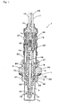
- Fig. 1 is a diagram showing the structure of an oxygen sensor according to an embodiment of the invention.
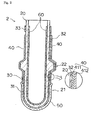
- Fig. 2 is a diagram showing a sectional portion of the oxygen sensor of Fig. 1.
- Fig. 3 is a diagram illustrating the structure of a detecting element of the oxygen sensor of Fig. 1.
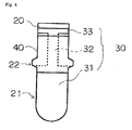
- Fig. 4 is another diagram illustrating the structure of the detecting element of the oxygen sensor of Fig. 1.
- Fig. 5 is a flow chart of manufacturing steps for providing the detecting element.
- Fig. 6 is a diagram illustrating a method for conducting an underwater insulation test of an insulating layer.
- Reference numerals used to identify various structural elements in the drawings include the following: 1 - - - OXYGEN SENSOR, 2 - - - DETECTING ELEMENT, 3 - - - HEATER, 5 - - - METAL SHELL, 7 - - - GASKET, 8, 9 - - - INSULATOR, 10 - - - POWDER LAYER, 11 - - - PROTECTOR, 12 - - - GAS PERMEATING HOLES, 13 - - - FILTER, 14 - - - GROMMET, 15 - - - CERAMIC SEPARATOR, 16, 17, 29 - - - LEAD WIRE, 18 - - - INNER ELECTRODE CONNECTING FITTING, 19 - - - OUTER ELECTRODE CONNECTING FITTING, 20 - - - ELEMENT BODY, 21 - - - DETEC
- FIG. 1 shows a schematic construction of the oxygen sensor according to one embodiment of the gas sensor of the invention.
- an oxygen sensor 1 is provided with a detecting element 2 as a gas detecting element, a heater 3, a metal shell 5 and other components.
- the heater 3 is made from a rod-shaped ceramic heater and is inserted into the detecting element 2.
- the metal shell 5 is equipped in its outer circumference with a thread 51 for mounting the oxygen sensor 1 on the mounting portion of an exhaust pipe or the like and with a bulge 53, to which a mounting fitting is applied when the sensor is mounted on the mounting portion of the exhaust pipe.
- the bulge 53 is equipped with a gasket 7 on its leading end face.
- the metal shell 5 is equipped on its inner circumference with a fitting side step 54 which is radially reduced toward the leading end side.
- insulators 8 and 9 Interposed between the metal shell 5 and the detecting element 2, moreover, are insulators 8 and 9 made from insulating ceramics.
- a powder layer 10 of talc or the like is sandwiched under compression between insulators 8 and 9. This powder layer 10 seals the gap between the detecting element 2 and the metal shell 5 to retain gas-tightness.
- a packing 55 is sandwiched between the leading end of the insulator 9 and the fitting side step 54, and an annular ring 57 is provided at the rear end of the insulator 8.
- a protector 11 is attached for covering a detecting portion 21 of the detecting element 2.
- This protector 11 is provided with a plurality of gas permeating holes 12 for introducing the gas to be measured.
- an inner cylinder member 23 is attached which is made of SUS304L.
- the inner cylinder member 23 is provided with gas inlet holes 25 for introducing a reference gas into the gas detecting element.
- an outer cylinder member 26 On the outer side of the inner cylinder member 23, an outer cylinder member 26 is provided, which is equipped with a plurality of auxiliary gas inlet holes 27 at positions corresponding to the gas inlet holes 25. Between the gas inlet holes 25 and the auxiliary gas inlet holes 27, moreover, a filter 13 is formed for covering the gas inlet holes 25. The filter 13 is fixed by additionally fastening the outer cylinder member 26 on the leading end side and the rear end side of the auxiliary gas inlet holes 27. On the inner side of the inner cylinder member 23, a ceramic separator 15 is formed.
- This ceramic separator 15 is housed by connecting an outer electrode connecting fitting 19 for connection to an outer electrode 30, an inner electrode connecting fitting 18 for connection to an inner electrode 60, and a heater connecting terminal 28 for connection to the heater 3, respectively, with corresponding lead wires 16, 17 and 29.
- lead wires 16, 17 and 29 are connected with the outside through a grommet 14 made of rubber, which is fixed on the rear end side of the outer cylinder member 26.
- the aforementioned oxygen sensor 1 is used in a state, in which its leading end side (as located on the lower side of Fig. 1) from the thread 51 is positioned in an exhaust pipe or the like and in which its rear end side (as located on the upper side of Fig. 1) from the same is positioned in the outside atmosphere.
- the detecting element 2 is heated and activated by the heater 3 arranged inside the detecting element 2.
- the outside atmosphere air
- the outside atmosphere air
- the exhaust gas is introduced to the outside of the detecting element 2 through the gas permeating holes 12 of the protector 11.
- an oxygen concentration electromotive force is generated according to a difference in oxygen concentration between the inner and outer faces of the detecting element 2.
- the oxygen concentration in the exhaust gas is detected by extracting the oxygen concentration electromotive force as a detection signal of the oxygen concentration in the exhaust gas through the inner electrode 60, the inner electrode connecting fitting 18 and the lead wire 17, and through the outer electrode 30, the outer electrode connecting fitting 19 and the lead wire 16.
- the detecting element 2 is equipped, as shown in Fig. 2, with an element body (or substrate) 20 of a bottomed cylindrical shape having its leading end closed.
- This element body 20 is made from an oxygen ion conductive solid electrolyte member mainly made from zirconia or the like.
- the element body 20 is equipped on the rear end side (as located on the upper side of Fig. 2) with a flange 22 protruding radially outward.
- Flange 22 is fixed, as shown in Fig. 1, on the insulator 9 through a packing 58.
- the sectional laminar structure of the detecting element 2 is schematically shown at an aspect ratio different from that of Fig. 1.
- an inner electrode 60 is provided, which is made of porous Pt or a Pt alloy, for example.
- the outer electrode 30 is formed, which is made of porous Pt or a Pt alloy, for example.
- a protecting layer 50 is formed, which is a sprayed layer of a ceramic such as spinel.
- This outer electrode 30 is constructed, as shown in Fig. 3, of the detecting electrode 31 formed to cover the section of the detecting portion 21 substantially, a lead portion 32 electrically connected to the detecting electrode 31 for extracting the electrode to the rear end side, and a ring portion 33. Over the entire area, from the rear end side portion of the detecting electrode 31 to the front of the ring terminal portion 33 of the lead portion 32, as shown in Fig. 2 and Fig. 4, an insulating layer 40 is formed so as to cover their outer side.
- the insulating layer 40 which is a characteristic feature of the invention is described as follows.
- the insulating layer 40 is interposed between the powder layer 10 and the portion of the lead portion 32 covered by the powder layer 10.
- this structure keeps the outer electrode 30 (mainly the lead portion 32) and the powder layer 10 from direct contact.
- the portion of the lead portion 32 i.e., the portion of lead portion 32 covered by the powder layer 10
- the insulating layer 40 so that direct contact between the lead portion 32 and the powder layer 10 is prevented.
- the requisite insulation properties are retained between the outer electrode 30 and the metal shell 5. Therefore, a short-circuit can be prevented between the metal shell and the lead portion, thus preventing noise from being introduced into the output and allowing for precise detection of gas concentration.
- This insulating layer 40 desirably has good insulation properties and heat resistance.
- the insulating layer 40 preferably is mainly made of glass (preferably at not less than 80% by weight, e.g. 100% by weight in this embodiment).
- the insulating layer 40 can include ceramic fillers e.g. alumina at less than 20 % by weight.
- This glass preferably has a low alkali metal element content so as not to cause a reduction in electrical insulation properties due to migration.
- the insulating layer 40 is formed of a plurality of layers. Specifically, the insulating layer 40 is formed of a first glass layer 411 and a second glass layer 412, which have identical components. Thus, the insulating layer 40 is formed of plural layers of the first glass layer 411 and the second glass layer 412, so that the insulating layer 40 can mainly be composed of glass having no pores, to thereby prevent a reduction in electrical insulation properties when pores are present. Moreover, the insulating layer 40 is crystallized, after being formed, to have a raised softening temperature so as to be hardly softened when the second glass layer 412 is to be formed. As a result, the second glass layer 412 can be formed of the same material as that of the first glass layer 411, to thereby thicken the insulating layer 40 and prevent a reduction in insulation properties.
- this insulating layer 40 extends so far as to be between the packing 58 and the flange 22. As a result, even if a portion of the powder layer 10 permeates to the rear end side of packing 58, it is possible to prevent a short-circuit, as might otherwise occur due to moisture absorption, between the metal shell 5 and the detecting electrode 31.
- insulating layer 40 extends in the leading end direction farther than the leading end of the metal shell 5.
- carbon or the like in the gas to be measured enters the gap 65, as formed in the leading end direction farther than the packing 58, between the detecting element 2 and the metal shell 5. Even if the carbon adheres to the surfaces of the gas detecting element and the metal shell, the insulating layer 40 effectively prevents a short-circuit, as might otherwise be caused by the carbon having been adhered, between the metal shell 5 and the detecting electrode or the lead portion 32.
- insulating layer 40 extends to the rear end of the detecting electrode 31, as shown in Fig. 4. As a result, it is possible to reliably prevent a short-circuit between the lead portions.
- the leading end side of the insulating layer 40 is covered with the protecting layer 50.
- the leading end side of the gas detecting element 2 at positions farther than the packing 58 is covered with either the protecting layer 50 or the insulating layer 40. Therefore, even if carbon or the like is deposited farther than the packing 58 in the leading end direction into the gap between the metal shell 5 and the gas detecting element 2 (so that the carbon or the like adheres to the metal shell 5 or the gas detecting element 2), electric current (leakage current) can be effectively prevented.
- the protecting layer 50 or the insulating layer 40 prevents electric current from flowing between the metal shell 5 and the detecting electrode 31 or the lead portion 32. As such, output noise is avoided, allowing for precise gas concentration detection.
- the protecting layer 50 covers the leading end portion of the insulating layer 40 so that the insulation property can be retained by the porous protecting layer 50 and the insulating layer 40.
- the substrate (the element body 20) which is made from an oxygen ion conductive solid electrolyte member or the like mainly composed of zirconia or the like is fired (at 101).
- the platinum electrode (the outer electrode 30) is formed (at 102) by electroless plating, and is densified (at 103) by heating.
- the heating is performed in air at a temperature of 1230 °C .
- the portion forming the insulating layer 40 on the substrate outer side is subjected to a first glass paste application (at 104).
- the dip method can be used, for example, in which the element body is dipped in glass paste by masking the element body other than the glass paste applied portion with TEFLON (Registered Trade Name) tape or the like.
- the glass paste contents are at ratios of 10 to 15 g of powder glass, 10 ml of pure water, and 0.1 to 1.0 g of binder.
- roller method in which glass paste is applied by bringing the element body into abutment against a roller while turning it in a direction opposite that of the roller
- spray method in which glass paste is sprayed on the element body while turning the element body
- the glass paste is dried (at 105) by means of a heat gun or the like, and is then to heat treated using a muffle furnace or the like to form the first glass layer 411 (at 106).
- This heat treatment is performed in air at a temperature of 1170 °C for a time period of 20 minutes, for example.
- a second glass paste application is performed similar to the first to the aforementioned glass layer (at 107), and is then dried (at 108).
- a heat treatment e.g., in air at a temperature of 1170 °C
- the first glass layer 411 has been crystallized so that it is hardly softened even by the heat treatment at 1170 °C.
- the insulating layer 40 is formed by applying the glass paste twice, so that the non-porous insulating layer 40 can be formed to prevent the insulation property from being lowered by pores, if any.
- the glass layer thus formed by these steps has a thickness of about 40 to 300 ⁇ m. If the thickness is less than 40 ⁇ m, sufficient insulation properties may not be obtained when operating the sensor.
- the protecting layer 50 is formed (at 110) by plasma spraying on the outer side of the detecting electrode 31.
- This protecting layer 50 is made from a ceramic porous layer of spinel or the like having a thickness of about 100 to 180 ⁇ m.
- the platinum electrode (the inner electrode 60) is formed (at 111) by an electroless plating, and is densified (at 103) by heating.
- the conditions for the densifying treatment are a reducing atmosphere of hydrogen or the like at a temperature of 700 °C.
- the detecting element 2 having the inner electrode 60 formed therein is held by a known method on the metal shell 5 through the packing 58 and the insulator 9, and is interior-finished by the powder layer 10, the insulator 8 and the annular ring 57 in the recited order.
- the inner cylinder member 23 is additionally fastened at its leading end portion by the rear end portion of the metal shell 5. After this, the outer cylinder member 26, the filter 13, the grommet 14 and so on are mounted to complete the oxygen sensor 1.
- the insulating layer 40 thus formed by the aforementioned manufacturing steps was subjected to an underwater insulation test.
- the element body 20 having the outer electrode 30 and the insulating layer 40 formed thereon was dipped in city water 70, as shown in Fig. 6, and the underwater insulation tests were conducted by measuring the insulation resistances with an insulation resistance tester 71.
- that portion of the element body 20 which did not have the insulating layer 40 on the rear end side (as located on the lower side of Fig. 6) was insulated by winding an insulating tape 72 of silicone.
- the underwater insulation tests were conducted by applying a DC voltage of 500 V and measuring the insulation resistances after charging for 10 seconds. As a result, the insulation resistance was about 5000 M ⁇ for the insulating layer 40 formed by the aforementioned manufacturing steps.
- the insulation resistance of the insulating layer 40 is sufficient if it has a value of about 15 M ⁇ . At a minimum value of about 5 M ⁇ , current flow can be suppressed to 1 ⁇ A or less to thereby to suppress the occurrence of noise. Therefore, the insulation resistance of the insulating layer 40 formed by the aforementioned measuring method is preferably 5 M ⁇ or higher, and more preferably 15 M ⁇ or higher.
- the oxygen sensor 1 having the insulating layer 40 formed to a thickness of 70 ⁇ m was prepared, as a First Example, with crystallized glass containing 45 wt. % of SiO 2 , 16 wt. % of Al 2 O 3 , 15 wt. % of BaO, 10 wt. % of ZnO, 9 wt. % of CaO and 0.5 wt. % of Na 2 O. Then, this oxygen sensor 1 was moistened in an environment of a temperature of 60 °C and a humidity of 95 % for 60 hours. After this, the insulation resistances were measured to be about 100 M ⁇ or more even immediately after being moistened. As a Comparative Example, on the other hand, similar measurements were conducted by the oxygen sensor 1 not having the insulating layer 40, and the insulating resistance was about 0.01 M ⁇ or less.
- the oxygen sensor 1 having the insulating layer 40 formed to a thickness of 70 ⁇ m was likewise prepared with amorphous glass containing 29 wt. % of SiO 2 , 54 wt. % of BaO, 4 wt. % of CaO, 3 wt. % of B 2 O 3 , and 0.5 wt. % of Na 2 O. Then, this oxygen sensor 1 was moistened in an environment of a temperature of 60 °C and a humidity of 95 % for 60 hours. After this, the insulation resistances were measured to be about 200 M ⁇ or more even immediately after being moistened. As a Comparative Example, on the other hand, similar measurements were conducted by the oxygen sensor 1 not having the insulating layer 40, and the insulating resistance was about 0.01 M ⁇ or less.
- the oxygen sensor 1 having the insulating layer 40 formed to a thickness of 70 ⁇ m was prepared with crystallized glass containing 32 wt. % of SiO 2 , 16 wt. % of Al 2 O 3 , 19 wt. % of CaO, 25 wt. % of ZnO, 10 wt. % of TiO 2 , 0.1 wt. % of Na 2 O and 0.04 wt. % of K 2 O. Then, this oxygen sensor 1 was moistened in an environment of a temperature of 60 °C and a humidity of 95 % for 60 hours. After this, the insulation resistances were measured to be about 100 M ⁇ or more even immediately after being moistened. As a Comparative Example, on the other hand, similar measurements were conducted by the oxygen sensor 1 not having the insulating layer 40, and the insulating resistance was about 0.01 M ⁇ or less.
- the examples of the invention could maintain insulating resistances 1,000 times as high as that of the oxygen sensor 1 of the prior art, and accordingly, provide an insulation property sufficient for suppressing the occurrence of noise.
- the insulating layer 40 is not to be construed as being limited to the above-specified materials, but may be made from any material so long as the material has an insulating resistance, preferably of 5 M ⁇ or higher, and more preferably of 15 M ⁇ or higher. Moreover, the insulating layer 40 can likewise be applied not only to the aforementioned oxygen sensor 1, but also to a gas sensor for detecting another kind of gas.
- the above described method of the embodiment is one in which the first glass layer 411 and the second glass layer 412 are formed, but the glass components can be changed between the first glass paste application and the second glass paste application.
- the second glass layer is preferably formed using a glass paste having a lower softening point than that of the first glass layer.
- the second glass layer can be formed by setting the second heat treatment temperature higher, within a range for maintaining the film thickness of the first glass layer, than that of the first heat treatment temperature. In this case, it is possible to improve adhesion between the first glass layer and the second glass layer.
Landscapes
- Chemical & Material Sciences (AREA)
- Life Sciences & Earth Sciences (AREA)
- Health & Medical Sciences (AREA)
- Physics & Mathematics (AREA)
- Chemical Kinetics & Catalysis (AREA)
- Electrochemistry (AREA)
- Molecular Biology (AREA)
- Analytical Chemistry (AREA)
- Biochemistry (AREA)
- General Health & Medical Sciences (AREA)
- General Physics & Mathematics (AREA)
- Immunology (AREA)
- Pathology (AREA)
- Measuring Oxygen Concentration In Cells (AREA)
Abstract
Description
- The present invention relates to a gas sensor for detecting a gas such as oxygen in a gas to be measured, which can be the exhaust gas of an internal combustion engine, and a method for manufacturing the gas sensor.
- A gas sensor, which has a bottomed cylindrical shape having its leading end closed and detecting electrodes on its inner and outer faces, is known for use in detecting a specific gas component in a gas to be measured, such as a gas sensor for detecting oxygen or the like in the exhaust gas of an internal combustion engine. In this gas sensor, the gas concentration is detected by introducing atmospheric air as a reference gas to the inner side of the gas detecting element, and by contacting the outer side with the gas to be measured. An electromotive force, developed according to the difference in gas concentration between the inside and outside of the detecting element, is measured.
- In this known gas sensor, moreover, a metallic housing (or a metal shell) encloses the gas detecting element so as to support the gas detecting element at a predetermined position. A gas sensor is also known in which a powder layer is arranged between the gas detecting element and the metallic housing so as to maintain gas-tightness therebetween (as disclosed by JP-A-2001-281209, for example).
- However, the gas sensors of the prior art thus far described have been found to have the following problems. Specifically, the powder layer absorbs moisture, if exposed to a humid environment (i.e., high humidity), so that there is a decrease in electrical resistance between the metallic housing and the outer electrode of the gas detecting element. As a result, an electric current flows therebetween to generate output noise, and precise gas concentration detection may be impaired.
- The present invention has been conceived to solve the aforementioned problems. Therefore, an object of the present invention is to provide a gas sensor capable of maintaining requisite insulation properties even in the case where a powder layer subjected to a humid environment may absorb moisture, and to a method for manufacturing the gas sensor.
- The above problems, and related problems, are solved by the gas sensor according to claim 1, and by the method according to
claim 9. Further details, improvements and preferred embodiments of the invention are disclosed in the dependent claims, the description and the figures. - In particular, the above objects of the invention have been achieved by providing a gas sensor comprising: a gas detecting element extending in an axial direction and including a detecting electrode provided on an outer surface of a leading end side, and a lead portion connecting to said detecting electrode and extending toward a rear end side; a cylindrical metal shell housing said gas detecting element such that said gas detecting element protrudes from a leading end side of said metal shell; and a powder layer filling a gap between said gas detecting element and said metal shell and covering at least a portion of said lead portion. The gas sensor is characterized as further comprising an insulating layer provided between said powder layer and the portion of said lead portion covered by the powder layer.
- The gas sensor of the invention is preferably imparted with such structure by interposing an insulating layer between the powder layer and the portion of the lead portion, so as to prevent direct contact between the portion of the lead portion covered by the powder layer and the powder layer. As a result, the desired insulation properties can be retained even in the case where the powder layer absorbs moisture when subjected to a humid environment. As a result, such structure can prevent electric current from flowing between the metal shell and the lead portion, so as to prevent noise generation in the output and thereby provide precise gas concentration detection measurements.
- The lead portion may extend over the outer circumference of the gas detecting element in a rear end direction farther than the rear end side of the powder layer. Moreover, the lead portion may be formed so as to extend over the entire circumference of the gas detecting element, or may be formed so as to extend in a rod shape in the circumferential portion of the gas detecting element toward the rear end side from the detecting electrode.
- In the gas sensor of the invention, the insulating layer preferably comprises glass, and more preferably the insulating layer is mainly (e.g. not less than 80 % by weight) composed of glass. The insulating layer can include some ceramic fillers made of e.g. alumina, preferably at less than 20% by weight. By providing an insulating layer comprising glass, the heat resistance can be retained while providing sufficient insulation properties.
- In the gas sensor of the invention, moreover, the insulating layer preferably includes a plurality of layers. As a result, an insulating layer mainly made from glass can be formed so as to have no pores, to thereby further prevent a reduction in insulation properties due to the presence of pores.
- In the gas sensor of the invention, of the plural layers, a first insulating layer adjacent to the lead portion is preferably made from crystallized glass. When the first insulating layer adjacent to the lead portion is made from crystallized glass, the first insulating layer is resistant to softening. Thus, the second insulating layer adjacent to the first insulating can be formed while maintaining the original thickness of the first insulating layer. As a result, an insulating layer having a large thickness can be formed to prevent a reduction in insulation properties.
- The gas detecting element may have a flange bulging to the radially outer side, and this flange plays a role in fixing the gas detecting element to the metal shell and the insulator through the packing. In the rear end direction farther than the packing, a portion of the powder layer may enter the gap between the gas detecting element and the metal shell or the insulator. The powder layer then absorbs moisture, as described above, so that the electric resistance between the metal shell and the detecting electrode of the gas detecting element or the lead portion is lowered. As a result, electric current may flow therebetween, and noise may be introduced into the output to interfere with precise gas concentration detection.
- In the gas sensor of the invention, therefore, it is preferable that the insulating layer preferably extends so far as to cover a portion of the flange contacting the packing. When the insulating layer extends so far as to cover a portion of the flange contacting the packing, a short-circuit between the metal shell and the detecting electrode or the lead portion can be prevented even if the powder layer provided at the portion of the flange contacting the packing absorbs moisture.
- The gap preferably is formed, in the leading end direction, farther than the packing between the gas detecting element and the metal shell. When the gas sensor is attached to an exhaust pipe or the like, the gap between the gas detecting element and the metal shell is exposed to the gas to be measured, so that carbon or the like in gas entering the gap adheres to the surfaces of the gas detecting element and the metal shell. The carbon may also adhere to the detecting electrode or the lead portion provided in the gas detecting element. As a result, the electrical resistance between the metal shell and the detecting electrode or the lead portion of the gas detecting element is lowered to allow an electric current to flow, and noise may be introduced into the output to interfere with precise gas concentration detection.
- In the gas sensor of the invention, therefore, the gas detecting element preferably includes a porous protecting layer covering at least a portion of the detecting electrode and lying over or rather overlapping at least the leading end portion of the insulating layer. On the outer circumference of the detecting electrode of the gas sensor, a protecting layer maybe provided for suppressing a reduction, as might otherwise be caused by a poisoning substance such as Pb in the gas to be measured, in the detecting precision of the gas sensor. By superposing the protecting layer and the insulating layer at its leading end side (that is, by covering that portion of the gas detecting element present beyond the packing in the leading end direction with the protecting layer and the insulating layer), the flow of electric current between the metal shell and the detecting element or the lead portion can be prevented by the protecting layer and the insulating layer. This is the case even if carbon or the like enters the gap between the metal shell and the gas detecting element and adheres to the metal shell and the gas detecting element This arrangement effectively prevents noise from being introduced into the output to thereby allow for precise gas concentration detection.
- In the gas sensor of the invention, therefore, the protecting layer preferably covers the leading end portion of the insulating layer. The insulating layer does not readily enter into the pores of the porous protecting layer, when covered by the protecting layer, and the protecting layer may not adversely affect the insulation properties. To the contrary, the insulation properties can be maintained, as in the invention, by covering the leading end portion of the insulating layer with the protecting layer.
- Moreover, the insulating layer preferably extends farther in the leading end direction than the leading end of the metal shell. As a result, even if carbon or the like adheres to the metal shell or the gas detecting element, the insulating layer can effectively prevent electric current flow between the metal shell and the detecting element or the lead portion, and prevent noise from being introduced into the output to allow for precise gas concentration detection.
- According to the invention, a gas sensor manufacturing method for manufacturing the gas sensor is characterized by forming the insulating layer by applying a glass paste, drying the glass paste, and heat-treating the glass paste. One preferable mode of the gas sensor manufacturing method of the invention is characterized in that a series of steps including the above application, drying and heat treatment steps are repeated at least two times to form the insulating layer. By carrying out these steps, it is possible to form an insulating layer having sufficient thickness, insulating properties and heat resistance.
- The invention, provides a gas sensor capable of maintaining good insulating properties even in the case where the powder layer is subjected to a humid environment so as to absorb moisture, and a method for manufacturing the gas sensor.
- Fig. 1 is a diagram showing the structure of an oxygen sensor according to an embodiment of the invention.
- Fig. 2 is a diagram showing a sectional portion of the oxygen sensor of Fig. 1.
- Fig. 3 is a diagram illustrating the structure of a detecting element of the oxygen sensor of Fig. 1.
- Fig. 4 is another diagram illustrating the structure of the detecting element of the oxygen sensor of Fig. 1.
- Fig. 5 is a flow chart of manufacturing steps for providing the detecting element.
- Fig. 6 is a diagram illustrating a method for conducting an underwater insulation test of an insulating layer.
- Reference numerals used to identify various structural elements in the drawings include the following: 1 - - - OXYGEN SENSOR, 2 - - - DETECTING ELEMENT, 3 - - - HEATER, 5 - - - METAL SHELL, 7 - - - GASKET, 8, 9 - - - INSULATOR, 10 - - - POWDER LAYER, 11 - - - PROTECTOR, 12 - - - GAS PERMEATING HOLES, 13 - - - FILTER, 14 - - - GROMMET, 15 - - - CERAMIC SEPARATOR, 16, 17, 29 - - - LEAD WIRE, 18 - - - INNER ELECTRODE CONNECTING FITTING, 19 - - - OUTER ELECTRODE CONNECTING FITTING, 20 - - - ELEMENT BODY, 21 - - - DETECTING PORTION, 22 - - - FLANGE, 23 - - - INNER CYLINDER MEMBER, 24 - - - STEP, 25 - - - GAS INLET HOLES, 26 - - - OUTER CYLINDER MEMBER, 27 - - - AUXILIARY GAS INLET HOLES, 28 - - - HEATER CONNECTING TERMINAL, 30 - - - OUTER ELECTRODE, 31 - - - DETECTING ELECTRODE, 32 - - - LEAD PORTION, 33 - - - RING PORTION, 40 - - - INSULATING LAYER, 50 - - - PROTECTING LAYER, 51 - - - THREAD, 52 - - - HEXAGONAL PORTION, 53 - - - BULGE, 54 - - - FITTING SIDE STEP, 55, 58 - - - PACKING, 56 - - - ADDITIONALLY FASTENED PORTION, 57 - - - ANNULAR RING, 60 - - - INNER ELECTRODE, and 71 - - - INSULATION RESISTANCE TESTER.
- An embodiment, in which a gas sensor of the invention is applied to an oxygen sensor, will be described with reference to the accompanying drawings. However, the prevent invention should not be construed as being limited thereto. Fig. 1 shows a schematic construction of the oxygen sensor according to one embodiment of the gas sensor of the invention.
- As shown in Fig. 1, an oxygen sensor 1 is provided with a detecting
element 2 as a gas detecting element, aheater 3, ametal shell 5 and other components. Of these, theheater 3 is made from a rod-shaped ceramic heater and is inserted into the detectingelement 2. - The
metal shell 5 is equipped in its outer circumference with athread 51 for mounting the oxygen sensor 1 on the mounting portion of an exhaust pipe or the like and with abulge 53, to which a mounting fitting is applied when the sensor is mounted on the mounting portion of the exhaust pipe. Here, thebulge 53 is equipped with agasket 7 on its leading end face. - The
metal shell 5 is equipped on its inner circumference with afitting side step 54 which is radially reduced toward the leading end side. Interposed between themetal shell 5 and the detectingelement 2, moreover, areinsulators powder layer 10 of talc or the like is sandwiched under compression betweeninsulators powder layer 10 seals the gap between the detectingelement 2 and themetal shell 5 to retain gas-tightness. A packing 55 is sandwiched between the leading end of theinsulator 9 and thefitting side step 54, and anannular ring 57 is provided at the rear end of theinsulator 8. - To the leading end side of the
metal shell 5, aprotector 11 is attached for covering a detectingportion 21 of the detectingelement 2. Thisprotector 11 is provided with a plurality ofgas permeating holes 12 for introducing the gas to be measured. - To the rear end side of the
metal shell 5, moreover, aninner cylinder member 23 is attached which is made of SUS304L. Theinner cylinder member 23 is provided with gas inlet holes 25 for introducing a reference gas into the gas detecting element. - On the outer side of the
inner cylinder member 23, anouter cylinder member 26 is provided, which is equipped with a plurality of auxiliary gas inlet holes 27 at positions corresponding to the gas inlet holes 25. Between the gas inlet holes 25 and the auxiliary gas inlet holes 27, moreover, afilter 13 is formed for covering the gas inlet holes 25. Thefilter 13 is fixed by additionally fastening theouter cylinder member 26 on the leading end side and the rear end side of the auxiliary gas inlet holes 27. On the inner side of theinner cylinder member 23, aceramic separator 15 is formed. Thisceramic separator 15 is housed by connecting an outer electrode connecting fitting 19 for connection to anouter electrode 30, an inner electrode connecting fitting 18 for connection to aninner electrode 60, and aheater connecting terminal 28 for connection to theheater 3, respectively, with correspondinglead wires lead wires grommet 14 made of rubber, which is fixed on the rear end side of theouter cylinder member 26. - The aforementioned oxygen sensor 1 is used in a state, in which its leading end side (as located on the lower side of Fig. 1) from the
thread 51 is positioned in an exhaust pipe or the like and in which its rear end side (as located on the upper side of Fig. 1) from the same is positioned in the outside atmosphere. The detectingelement 2 is heated and activated by theheater 3 arranged inside the detectingelement 2. Moreover, the outside atmosphere (air), as a reference gas, is introduced into the detectingelement 2 through the auxiliary gas inlet holes 27, thefilter 13 and the gas inlet holes 25 in the recited order. The exhaust gas is introduced to the outside of the detectingelement 2 through thegas permeating holes 12 of theprotector 11. - As a result, an oxygen concentration electromotive force is generated according to a difference in oxygen concentration between the inner and outer faces of the detecting
element 2. Moreover, the oxygen concentration in the exhaust gas is detected by extracting the oxygen concentration electromotive force as a detection signal of the oxygen concentration in the exhaust gas through theinner electrode 60, the innerelectrode connecting fitting 18 and thelead wire 17, and through theouter electrode 30, the outerelectrode connecting fitting 19 and thelead wire 16. - Next, the detecting
element 2 is described with reference to Figs. 2 to 4. - The detecting
element 2 is equipped, as shown in Fig. 2, with an element body (or substrate) 20 of a bottomed cylindrical shape having its leading end closed. Thiselement body 20 is made from an oxygen ion conductive solid electrolyte member mainly made from zirconia or the like. Moreover, theelement body 20 is equipped on the rear end side (as located on the upper side of Fig. 2) with aflange 22 protruding radially outward.Flange 22 is fixed, as shown in Fig. 1, on theinsulator 9 through a packing 58. In Fig. 2, the sectional laminar structure of the detectingelement 2 is schematically shown at an aspect ratio different from that of Fig. 1. - On the inner side of the
element body 20, moreover, aninner electrode 60 is provided, which is made of porous Pt or a Pt alloy, for example. On the outer side of theelement body 20, theouter electrode 30 is formed, which is made of porous Pt or a Pt alloy, for example. On the outer side of a detectingelectrode 31, a protectinglayer 50 is formed, which is a sprayed layer of a ceramic such as spinel. - This
outer electrode 30 is constructed, as shown in Fig. 3, of the detectingelectrode 31 formed to cover the section of the detectingportion 21 substantially, alead portion 32 electrically connected to the detectingelectrode 31 for extracting the electrode to the rear end side, and aring portion 33. Over the entire area, from the rear end side portion of the detectingelectrode 31 to the front of thering terminal portion 33 of thelead portion 32, as shown in Fig. 2 and Fig. 4, an insulatinglayer 40 is formed so as to cover their outer side. - The insulating
layer 40 which is a characteristic feature of the invention is described as follows. The insulatinglayer 40 is interposed between thepowder layer 10 and the portion of thelead portion 32 covered by thepowder layer 10. As a result, this structure keeps the outer electrode 30 (mainly the lead portion 32) and thepowder layer 10 from direct contact. By employing this structure, even if thepowder layer 10 absorbs moisture, the portion of the lead portion 32 (i.e., the portion oflead portion 32 covered by the powder layer 10) is covered by thepowder layer 10 via the insulatinglayer 40 so that direct contact between thelead portion 32 and thepowder layer 10 is prevented. As a result, the requisite insulation properties are retained between theouter electrode 30 and themetal shell 5. Therefore, a short-circuit can be prevented between the metal shell and the lead portion, thus preventing noise from being introduced into the output and allowing for precise detection of gas concentration. - This insulating
layer 40 desirably has good insulation properties and heat resistance. Thus, the insulatinglayer 40 preferably is mainly made of glass (preferably at not less than 80% by weight, e.g. 100% by weight in this embodiment). The insulatinglayer 40 can include ceramic fillers e.g. alumina at less than 20 % by weight. This glass preferably has a low alkali metal element content so as not to cause a reduction in electrical insulation properties due to migration. - As shown in Fig. 2, moreover, the insulating
layer 40 is formed of a plurality of layers. Specifically, the insulatinglayer 40 is formed of afirst glass layer 411 and asecond glass layer 412, which have identical components. Thus, the insulatinglayer 40 is formed of plural layers of thefirst glass layer 411 and thesecond glass layer 412, so that the insulatinglayer 40 can mainly be composed of glass having no pores, to thereby prevent a reduction in electrical insulation properties when pores are present. Moreover, the insulatinglayer 40 is crystallized, after being formed, to have a raised softening temperature so as to be hardly softened when thesecond glass layer 412 is to be formed. As a result, thesecond glass layer 412 can be formed of the same material as that of thefirst glass layer 411, to thereby thicken the insulatinglayer 40 and prevent a reduction in insulation properties. - Moreover, this insulating
layer 40 extends so far as to be between the packing 58 and theflange 22. As a result, even if a portion of thepowder layer 10 permeates to the rear end side of packing 58, it is possible to prevent a short-circuit, as might otherwise occur due to moisture absorption, between themetal shell 5 and the detectingelectrode 31. - Moreover, insulating
layer 40 extends in the leading end direction farther than the leading end of themetal shell 5. When the gas sensor 1 is attached to an exhaust pipe or the like, carbon or the like in the gas to be measured enters thegap 65, as formed in the leading end direction farther than the packing 58, between the detectingelement 2 and themetal shell 5. Even if the carbon adheres to the surfaces of the gas detecting element and the metal shell, the insulatinglayer 40 effectively prevents a short-circuit, as might otherwise be caused by the carbon having been adhered, between themetal shell 5 and the detecting electrode or thelead portion 32. - Moreover, insulating
layer 40 extends to the rear end of the detectingelectrode 31, as shown in Fig. 4. As a result, it is possible to reliably prevent a short-circuit between the lead portions. - As shown in Fig. 2, the leading end side of the insulating
layer 40 is covered with the protectinglayer 50. As a result, the leading end side of thegas detecting element 2 at positions farther than the packing 58 is covered with either the protectinglayer 50 or the insulatinglayer 40. Therefore, even if carbon or the like is deposited farther than the packing 58 in the leading end direction into the gap between themetal shell 5 and the gas detecting element 2 (so that the carbon or the like adheres to themetal shell 5 or the gas detecting element 2), electric current (leakage current) can be effectively prevented. In this regard, the protectinglayer 50 or the insulatinglayer 40 prevents electric current from flowing between themetal shell 5 and the detectingelectrode 31 or thelead portion 32. As such, output noise is avoided, allowing for precise gas concentration detection. - Especially, the protecting
layer 50 covers the leading end portion of the insulatinglayer 40 so that the insulation property can be retained by theporous protecting layer 50 and the insulatinglayer 40. - Next, a method for manufacturing the detecting
element 2 is described with reference to Fig. 5. As shown in Fig. 5, the substrate (the element body 20) which is made from an oxygen ion conductive solid electrolyte member or the like mainly composed of zirconia or the like is fired (at 101). - Next, the platinum electrode (the outer electrode 30) is formed (at 102) by electroless plating, and is densified (at 103) by heating. The heating is performed in air at a temperature of 1230 °C .
- Next, the portion forming the insulating
layer 40 on the substrate outer side is subjected to a first glass paste application (at 104). For this glass paste application, the dip method can be used, for example, in which the element body is dipped in glass paste by masking the element body other than the glass paste applied portion with TEFLON (Registered Trade Name) tape or the like. In this case, the glass paste contents are at ratios of 10 to 15 g of powder glass, 10 ml of pure water, and 0.1 to 1.0 g of binder. It is also possible to use the roller method, in which glass paste is applied by bringing the element body into abutment against a roller while turning it in a direction opposite that of the roller, or the spray method, in which glass paste is sprayed on the element body while turning the element body. - Next, the glass paste is dried (at 105) by means of a heat gun or the like, and is then to heat treated using a muffle furnace or the like to form the first glass layer 411 (at 106). This heat treatment is performed in air at a temperature of 1170 °C for a time period of 20 minutes, for example.
- Next, a second glass paste application is performed similar to the first to the aforementioned glass layer (at 107), and is then dried (at 108). After this, a heat treatment (e.g., in air at a temperature of 1170 °C) is conducted to form the second glass layer (at 109). The
first glass layer 411 has been crystallized so that it is hardly softened even by the heat treatment at 1170 °C. Thus, the insulatinglayer 40 is formed by applying the glass paste twice, so that the non-porous insulatinglayer 40 can be formed to prevent the insulation property from being lowered by pores, if any. The glass layer thus formed by these steps has a thickness of about 40 to 300 µm. If the thickness is less than 40 µm, sufficient insulation properties may not be obtained when operating the sensor. - Next, the protecting
layer 50 is formed (at 110) by plasma spraying on the outer side of the detectingelectrode 31. This protectinglayer 50 is made from a ceramic porous layer of spinel or the like having a thickness of about 100 to 180 µm. - Next, the platinum electrode (the inner electrode 60) is formed (at 111) by an electroless plating, and is densified (at 103) by heating. The conditions for the densifying treatment are a reducing atmosphere of hydrogen or the like at a temperature of 700 °C.
- Then, the detecting
element 2 having theinner electrode 60 formed therein is held by a known method on themetal shell 5 through the packing 58 and theinsulator 9, and is interior-finished by thepowder layer 10, theinsulator 8 and theannular ring 57 in the recited order. Theinner cylinder member 23 is additionally fastened at its leading end portion by the rear end portion of themetal shell 5. After this, theouter cylinder member 26, thefilter 13, thegrommet 14 and so on are mounted to complete the oxygen sensor 1. - Next, the insulating
layer 40 thus formed by the aforementioned manufacturing steps was subjected to an underwater insulation test. Specifically, theelement body 20 having theouter electrode 30 and the insulatinglayer 40 formed thereon was dipped incity water 70, as shown in Fig. 6, and the underwater insulation tests were conducted by measuring the insulation resistances with aninsulation resistance tester 71. Here, that portion of theelement body 20 which did not have the insulatinglayer 40 on the rear end side (as located on the lower side of Fig. 6) was insulated by winding an insulatingtape 72 of silicone. The underwater insulation tests were conducted by applying a DC voltage of 500 V and measuring the insulation resistances after charging for 10 seconds. As a result, the insulation resistance was about 5000 MΩ for the insulatinglayer 40 formed by the aforementioned manufacturing steps. - For practical use, the insulation resistance of the insulating
layer 40 is sufficient if it has a value of about 15 MΩ. At a minimum value of about 5 MΩ, current flow can be suppressed to 1 µA or less to thereby to suppress the occurrence of noise. Therefore, the insulation resistance of the insulatinglayer 40 formed by the aforementioned measuring method is preferably 5 MΩ or higher, and more preferably 15 MΩ or higher. - Practically, the oxygen sensor 1 having the insulating
layer 40 formed to a thickness of 70 µm was prepared, as a First Example, with crystallized glass containing 45 wt. % of SiO2, 16 wt. % of Al2O3, 15 wt. % of BaO, 10 wt. % of ZnO, 9 wt. % of CaO and 0.5 wt. % of Na2O. Then, this oxygen sensor 1 was moistened in an environment of a temperature of 60 °C and a humidity of 95 % for 60 hours. After this, the insulation resistances were measured to be about 100 MΩ or more even immediately after being moistened. As a Comparative Example, on the other hand, similar measurements were conducted by the oxygen sensor 1 not having the insulatinglayer 40, and the insulating resistance was about 0.01 MΩ or less. - As a Second Example, the oxygen sensor 1 having the insulating
layer 40 formed to a thickness of 70 µm was likewise prepared with amorphous glass containing 29 wt. % of SiO2, 54 wt. % of BaO, 4 wt. % of CaO, 3 wt. % of B2O3, and 0.5 wt. % of Na2O. Then, this oxygen sensor 1 was moistened in an environment of a temperature of 60 °C and a humidity of 95 % for 60 hours. After this, the insulation resistances were measured to be about 200 MΩ or more even immediately after being moistened. As a Comparative Example, on the other hand, similar measurements were conducted by the oxygen sensor 1 not having the insulatinglayer 40, and the insulating resistance was about 0.01 MΩ or less. - Likewise, as a Third Example, the oxygen sensor 1 having the insulating
layer 40 formed to a thickness of 70 µm was prepared with crystallized glass containing 32 wt. % of SiO2, 16 wt. % of Al2O3, 19 wt. % of CaO, 25 wt. % of ZnO, 10 wt. % of TiO2, 0.1 wt. % of Na2O and 0.04 wt. % of K2O. Then, this oxygen sensor 1 was moistened in an environment of a temperature of 60 °C and a humidity of 95 % for 60 hours. After this, the insulation resistances were measured to be about 100 MΩ or more even immediately after being moistened. As a Comparative Example, on the other hand, similar measurements were conducted by the oxygen sensor 1 not having the insulatinglayer 40, and the insulating resistance was about 0.01 MΩ or less. - As described above, the examples of the invention could maintain insulating resistances 1,000 times as high as that of the oxygen sensor 1 of the prior art, and accordingly, provide an insulation property sufficient for suppressing the occurrence of noise.
- The insulating
layer 40 is not to be construed as being limited to the above-specified materials, but may be made from any material so long as the material has an insulating resistance, preferably of 5 MΩ or higher, and more preferably of 15 MΩ or higher. Moreover, the insulatinglayer 40 can likewise be applied not only to the aforementioned oxygen sensor 1, but also to a gas sensor for detecting another kind of gas. - Moreover, the above described method of the embodiment is one in which the
first glass layer 411 and thesecond glass layer 412 are formed, but the glass components can be changed between the first glass paste application and the second glass paste application. In a case where the first glass layer is not crystallized, the second glass layer is preferably formed using a glass paste having a lower softening point than that of the first glass layer. By using a glass paste for the first glass layer having a higher softening point than that of the glass plate, moreover, the second glass layer can be formed by setting the second heat treatment temperature higher, within a range for maintaining the film thickness of the first glass layer, than that of the first heat treatment temperature. In this case, it is possible to improve adhesion between the first glass layer and the second glass layer. - It should further be apparent to those skilled in the art that various changes in form and detail of the invention as shown and described above may be made. It is intended that such changes be included within the spirit and scope of the claims appended hereto.
- This application is based on Japanese Patent application JP 2004-346331, filed November 30, 2004, and Japanese Patent application JP 2005-302311, filed October 17, 2005 the entire contents of which are hereby incorporated by reference, the same as if set forth at length.
Claims (10)
- A gas sensor (1) comprising:a gas detecting element (2) extending in an axial direction and including a detecting electrode (31) provided on an outer surface of a leading end side of said gas detecting element (2), and a lead portion (32) connecting to said detecting electrode (31) and extending toward a rear end side of said gas detecting element (2);a cylindrical metal shell (5) housing said gas detecting element (2) such that said gas detecting element protrudes from a leading end side of said metal shell (5);a powder layer (10) filling a gap between said gas detecting element (2) and said metal shell (5) and covering at least a portion of said lead portion (32); andan insulating layer (40) provided between said powder layer (10) and the portion of said lead portion (32) covered by the powder layer (10).
- The gas sensor as claimed in claim 1, wherein said insulating layer (40) comprises glass.
- The gas sensor as claimed in claim 1 or 2, wherein said insulating layer (40) includes a plurality of layers.
- The gas sensor as claimed in claim 3, wherein said plurality of layers includes a first insulating layer arranged adjacent to said lead portion (32), and said first insulating layer (40) comprises crystallized glass.
- The gas sensor according to any one of the claims 1-4, further comprising a packing (58) provided farther than said powder layer (10) in a leading end direction, wherein said gas detecting element (2) includes a flange (22) bulging to a radially outer side and contacting said packing (58); and said insulating layer (40)extends to cover a portion of said flange (22)contacting said packing.
- The gas sensor according to any one of the claims 1-5, wherein said gas detecting element (2) includes a porous protecting layer (50) covering at least a portion of said detecting electrode (31) and overlapping at least a leading end portion of said insulating layer (40).
- The gas sensor as claimed in claim 6, wherein said protecting layer (50) covers a leading end portion of said insulating layer (40).
- The gas sensor according to any one of the claims 1-7, wherein said insulating layer (40) extends beyond a leading end of said metal shell (5) in a leading end direction.
- A method for manufacturing the gas sensor (2) as claimed in any one of the claims 1-8, the method comprising forming said insulating layer by at least:applying a glass paste;drying said glass paste; andheat-treating said glass paste.
- The method as claimed in claim 9, wherein a series of steps including said applying, said drying and said heat treating steps are repeated at least two times to form said insulating layer.
Applications Claiming Priority (1)
| Application Number | Priority Date | Filing Date | Title |
|---|---|---|---|
| JP2004346331 | 2004-11-30 |
Publications (3)
| Publication Number | Publication Date |
|---|---|
| EP1662253A2 true EP1662253A2 (en) | 2006-05-31 |
| EP1662253A3 EP1662253A3 (en) | 2006-06-21 |
| EP1662253B1 EP1662253B1 (en) | 2016-11-23 |
Family
ID=35731231
Family Applications (1)
| Application Number | Title | Priority Date | Filing Date |
|---|---|---|---|
| EP05026113.0A Ceased EP1662253B1 (en) | 2004-11-30 | 2005-11-30 | Gas sensor, and gas sensor manufacturing method |
Country Status (3)
| Country | Link |
|---|---|
| US (1) | US8257564B2 (en) |
| EP (1) | EP1662253B1 (en) |
| CN (1) | CN100575942C (en) |
Cited By (1)
| Publication number | Priority date | Publication date | Assignee | Title |
|---|---|---|---|---|
| WO2014024018A1 (en) * | 2012-08-07 | 2014-02-13 | Toyota Jidosha Kabushiki Kaisha | Exhaust gas sensor |
Families Citing this family (8)
| Publication number | Priority date | Publication date | Assignee | Title |
|---|---|---|---|---|
| US7520160B1 (en) * | 2007-10-04 | 2009-04-21 | Schlumberger Technology Corporation | Electrochemical sensor |
| JP5638984B2 (en) * | 2010-03-11 | 2014-12-10 | 日本特殊陶業株式会社 | Gas sensor |
| CN102182572A (en) * | 2011-01-21 | 2011-09-14 | 上海赛赛汽车技术服务有限公司 | Oxygen sensor |
| JP5639032B2 (en) * | 2011-11-08 | 2014-12-10 | 日本特殊陶業株式会社 | Gas sensor element and gas sensor |
| CN106093165A (en) * | 2016-08-17 | 2016-11-09 | 苏州工业园区传世汽车电子有限公司 | Oxygen sensor zirconium element external electrode pilot protection structure and preparation method thereof |
| CN110794023B (en) * | 2019-11-07 | 2021-12-14 | 中国电子科技集团公司第四十九研究所 | A kind of partial pressure oxygen sensor with ceramic heater structure and preparation method thereof |
| JP7259770B2 (en) * | 2020-01-08 | 2023-04-18 | 株式会社デンソー | Dip device |
| CN115714088A (en) * | 2022-12-05 | 2023-02-24 | 济南晶久电子科技有限公司 | Processing method of glass sintering high-voltage bridge rectifier |
Family Cites Families (17)
| Publication number | Priority date | Publication date | Assignee | Title |
|---|---|---|---|---|
| JPS5819553A (en) * | 1981-07-27 | 1983-02-04 | Nippon Denso Co Ltd | Multifunctional oxygen concentration detector |
| JPS60179862U (en) | 1984-05-07 | 1985-11-29 | 株式会社デンソー | oxygen concentration detector |
| JPS60183857U (en) | 1984-05-07 | 1985-12-06 | 株式会社デンソー | oxygen concentration detector |
| JPH0833369B2 (en) | 1986-06-24 | 1996-03-29 | 日本特殊陶業株式会社 | Oxygen sensor |
| JPS633250A (en) | 1986-06-24 | 1988-01-08 | Ngk Spark Plug Co Ltd | Oxygen sensor |
| JPH0778482B2 (en) | 1987-11-26 | 1995-08-23 | 日本特殊陶業株式会社 | Oxygen sensor |
| DE4318789A1 (en) * | 1993-06-05 | 1994-12-08 | Bosch Gmbh Robert | Seal for a sensor element of a gas sensor |
| RU2138800C1 (en) | 1993-07-27 | 1999-09-27 | Роберт Бош Гмбх | Electrochemical metering probe with potentially loose sensing element and its manufacturing process |
| US5536574A (en) * | 1993-08-02 | 1996-07-16 | Loral Vought Systems Corporation | Oxidation protection for carbon/carbon composites |
| DE4400370A1 (en) | 1994-01-11 | 1995-07-13 | Bosch Gmbh Robert | Electrochemical sensor with a potential-free sensor element |
| DE9409684U1 (en) * | 1994-06-16 | 1995-10-12 | Robert Bosch Gmbh, 70469 Stuttgart | Electrochemical sensor |
| JP3588848B2 (en) | 1995-02-07 | 2004-11-17 | 株式会社デンソー | Oxygen concentration detector |
| US5935399A (en) * | 1996-01-31 | 1999-08-10 | Denso Corporation | Air-fuel ratio sensor |
| DE19641808A1 (en) | 1996-10-10 | 1998-04-16 | Bosch Gmbh Robert | Sealing element for sensors and method for its manufacture |
| JP4476500B2 (en) | 2000-01-27 | 2010-06-09 | 日本特殊陶業株式会社 | Gas sensor |
| US6565723B1 (en) * | 2000-12-04 | 2003-05-20 | Delphi Technologies, Inc. | Isolated ground sensor achieved using alumina coating over spinel coating |
| DE10127917C1 (en) * | 2001-06-08 | 2002-12-12 | Bosch Gmbh Robert | Gas sensor used as lambda sensor in IC engines comprises housing with sealing packing holding ceramic sensor body having coating made from electrically insulating material |
-
2005
- 2005-11-29 US US11/288,372 patent/US8257564B2/en not_active Expired - Fee Related
- 2005-11-30 EP EP05026113.0A patent/EP1662253B1/en not_active Ceased
- 2005-11-30 CN CN200510127089A patent/CN100575942C/en not_active Expired - Fee Related
Non-Patent Citations (1)
| Title |
|---|
| None |
Cited By (2)
| Publication number | Priority date | Publication date | Assignee | Title |
|---|---|---|---|---|
| WO2014024018A1 (en) * | 2012-08-07 | 2014-02-13 | Toyota Jidosha Kabushiki Kaisha | Exhaust gas sensor |
| US9297779B2 (en) | 2012-08-07 | 2016-03-29 | Toyota Jidosha Kabushiki Kaisha | Exhaust gas sensor |
Also Published As
| Publication number | Publication date |
|---|---|
| EP1662253B1 (en) | 2016-11-23 |
| US20060113188A1 (en) | 2006-06-01 |
| CN100575942C (en) | 2009-12-30 |
| US8257564B2 (en) | 2012-09-04 |
| CN1782703A (en) | 2006-06-07 |
| EP1662253A3 (en) | 2006-06-21 |
Similar Documents
| Publication | Publication Date | Title |
|---|---|---|
| EP2818855B1 (en) | Gas sensor element and gas sensor | |
| US8992752B2 (en) | Gas sensor element and gas sensor | |
| US4402820A (en) | Oxygen analyzer | |
| US9291525B2 (en) | Gas sensor element and gas sensor | |
| EP0182485B1 (en) | Gas sensing element | |
| EP1178303B1 (en) | Gas sensor element and manufacturing method thereof | |
| US20070095662A1 (en) | Structure of gas element ensuring high catalytic activity and conductivity and production method thereof | |
| JPS6336461B2 (en) | ||
| JPS61108953A (en) | Electrical connecting terminal of sensor element using ceramics | |
| US5935399A (en) | Air-fuel ratio sensor | |
| US4642174A (en) | Apparatus for determining the oxygen content in gases | |
| US6344118B1 (en) | Structure of oxygen sensing element | |
| US8257564B2 (en) | Gas sensor, and gas sensor manufacturing method | |
| US20220113276A1 (en) | Gas sensor and method of manufacture thereof | |
| JPS6337893B2 (en) | ||
| US4313810A (en) | Oxygen concentration sensing apparatus | |
| JP3677920B2 (en) | Oxygen concentration detector | |
| JP4605783B2 (en) | Gas sensor and gas sensor manufacturing method | |
| JP4384994B2 (en) | Gas sensor and gas sensor manufacturing method | |
| JPH0418619B2 (en) | ||
| JP2005351741A (en) | Oxygen concentration detection element | |
| JP4540222B2 (en) | Oxygen sensor and manufacturing method thereof | |
| JPH10206380A (en) | Oxygen concentration detection element | |
| JP2004150811A (en) | Carbon monoxide sensor | |
| JPS6034064B2 (en) | Stacked membrane structure oxygen sensor |
Legal Events
| Date | Code | Title | Description |
|---|---|---|---|
| PUAI | Public reference made under article 153(3) epc to a published international application that has entered the european phase |
Free format text: ORIGINAL CODE: 0009012 |
|
| PUAL | Search report despatched |
Free format text: ORIGINAL CODE: 0009013 |
|
| AK | Designated contracting states |
Kind code of ref document: A2 Designated state(s): AT BE BG CH CY CZ DE DK EE ES FI FR GB GR HU IE IS IT LI LT LU LV MC NL PL PT RO SE SI SK TR |
|
| AX | Request for extension of the european patent |
Extension state: AL BA HR MK YU |
|
| AK | Designated contracting states |
Kind code of ref document: A3 Designated state(s): AT BE BG CH CY CZ DE DK EE ES FI FR GB GR HU IE IS IT LI LT LU LV MC NL PL PT RO SE SI SK TR |
|
| AX | Request for extension of the european patent |
Extension state: AL BA HR MK YU |
|
| 17P | Request for examination filed |
Effective date: 20060516 |
|
| AKX | Designation fees paid |
Designated state(s): DE FR |
|
| 17Q | First examination report despatched |
Effective date: 20110418 |
|
| RAP1 | Party data changed (applicant data changed or rights of an application transferred) |
Owner name: NGK SPARK PLUG CO., LTD. |
|
| GRAP | Despatch of communication of intention to grant a patent |
Free format text: ORIGINAL CODE: EPIDOSNIGR1 |
|
| INTG | Intention to grant announced |
Effective date: 20160616 |
|
| RIN1 | Information on inventor provided before grant (corrected) |
Inventor name: MORI, KENTARO Inventor name: SHIONO, KOJI |
|
| GRAS | Grant fee paid |
Free format text: ORIGINAL CODE: EPIDOSNIGR3 |
|
| GRAA | (expected) grant |
Free format text: ORIGINAL CODE: 0009210 |
|
| REG | Reference to a national code |
Ref country code: FR Ref legal event code: PLFP Year of fee payment: 12 |
|
| AK | Designated contracting states |
Kind code of ref document: B1 Designated state(s): DE FR |
|
| REG | Reference to a national code |
Ref country code: DE Ref legal event code: R096 Ref document number: 602005050733 Country of ref document: DE |
|
| REG | Reference to a national code |
Ref country code: DE Ref legal event code: R096 Ref document number: 602005050733 Country of ref document: DE |
|
| REG | Reference to a national code |
Ref country code: DE Ref legal event code: R097 Ref document number: 602005050733 Country of ref document: DE |
|
| PLBE | No opposition filed within time limit |
Free format text: ORIGINAL CODE: 0009261 |
|
| STAA | Information on the status of an ep patent application or granted ep patent |
Free format text: STATUS: NO OPPOSITION FILED WITHIN TIME LIMIT |
|
| REG | Reference to a national code |
Ref country code: FR Ref legal event code: PLFP Year of fee payment: 13 |
|
| 26N | No opposition filed |
Effective date: 20170824 |
|
| PGFP | Annual fee paid to national office [announced via postgrant information from national office to epo] |
Ref country code: FR Payment date: 20171012 Year of fee payment: 13 |
|
| PG25 | Lapsed in a contracting state [announced via postgrant information from national office to epo] |
Ref country code: FR Free format text: LAPSE BECAUSE OF NON-PAYMENT OF DUE FEES Effective date: 20181130 |
|
| PGFP | Annual fee paid to national office [announced via postgrant information from national office to epo] |
Ref country code: DE Payment date: 20211005 Year of fee payment: 17 |
|
| REG | Reference to a national code |
Ref country code: DE Ref legal event code: R119 Ref document number: 602005050733 Country of ref document: DE |
|
| PG25 | Lapsed in a contracting state [announced via postgrant information from national office to epo] |
Ref country code: DE Free format text: LAPSE BECAUSE OF NON-PAYMENT OF DUE FEES Effective date: 20230601 |