EP1662237B1 - Füllstandsmessgerät - Google Patents
Füllstandsmessgerät Download PDFInfo
- Publication number
- EP1662237B1 EP1662237B1 EP05109107.2A EP05109107A EP1662237B1 EP 1662237 B1 EP1662237 B1 EP 1662237B1 EP 05109107 A EP05109107 A EP 05109107A EP 1662237 B1 EP1662237 B1 EP 1662237B1
- Authority
- EP
- European Patent Office
- Prior art keywords
- digital samples
- digital
- signal processing
- echo
- level measurement
- Prior art date
- Legal status (The legal status is an assumption and is not a legal conclusion. Google has not performed a legal analysis and makes no representation as to the accuracy of the status listed.)
- Ceased
Links
Images


Classifications
-
- G—PHYSICS
- G01—MEASURING; TESTING
- G01F—MEASURING VOLUME, VOLUME FLOW, MASS FLOW OR LIQUID LEVEL; METERING BY VOLUME
- G01F23/00—Indicating or measuring liquid level or level of fluent solid material, e.g. indicating in terms of volume or indicating by means of an alarm
- G01F23/22—Indicating or measuring liquid level or level of fluent solid material, e.g. indicating in terms of volume or indicating by means of an alarm by measuring physical variables, other than linear dimensions, pressure or weight, dependent on the level to be measured, e.g. by difference of heat transfer of steam or water
- G01F23/28—Indicating or measuring liquid level or level of fluent solid material, e.g. indicating in terms of volume or indicating by means of an alarm by measuring physical variables, other than linear dimensions, pressure or weight, dependent on the level to be measured, e.g. by difference of heat transfer of steam or water by measuring the variations of parameters of electromagnetic or acoustic waves applied directly to the liquid or fluent solid material
- G01F23/284—Electromagnetic waves
-
- G—PHYSICS
- G01—MEASURING; TESTING
- G01F—MEASURING VOLUME, VOLUME FLOW, MASS FLOW OR LIQUID LEVEL; METERING BY VOLUME
- G01F23/00—Indicating or measuring liquid level or level of fluent solid material, e.g. indicating in terms of volume or indicating by means of an alarm
- G01F23/22—Indicating or measuring liquid level or level of fluent solid material, e.g. indicating in terms of volume or indicating by means of an alarm by measuring physical variables, other than linear dimensions, pressure or weight, dependent on the level to be measured, e.g. by difference of heat transfer of steam or water
- G01F23/28—Indicating or measuring liquid level or level of fluent solid material, e.g. indicating in terms of volume or indicating by means of an alarm by measuring physical variables, other than linear dimensions, pressure or weight, dependent on the level to be measured, e.g. by difference of heat transfer of steam or water by measuring the variations of parameters of electromagnetic or acoustic waves applied directly to the liquid or fluent solid material
- G01F23/296—Acoustic waves
- G01F23/2962—Measuring transit time of reflected waves
-
- G—PHYSICS
- G01—MEASURING; TESTING
- G01S—RADIO DIRECTION-FINDING; RADIO NAVIGATION; DETERMINING DISTANCE OR VELOCITY BY USE OF RADIO WAVES; LOCATING OR PRESENCE-DETECTING BY USE OF THE REFLECTION OR RERADIATION OF RADIO WAVES; ANALOGOUS ARRANGEMENTS USING OTHER WAVES
- G01S13/00—Systems using the reflection or reradiation of radio waves, e.g. radar systems; Analogous systems using reflection or reradiation of waves whose nature or wavelength is irrelevant or unspecified
- G01S13/02—Systems using reflection of radio waves, e.g. primary radar systems; Analogous systems
- G01S13/06—Systems determining position data of a target
- G01S13/08—Systems for measuring distance only
- G01S13/10—Systems for measuring distance only using transmission of interrupted, pulse modulated waves
- G01S13/103—Systems for measuring distance only using transmission of interrupted, pulse modulated waves particularities of the measurement of the distance
-
- G—PHYSICS
- G01—MEASURING; TESTING
- G01S—RADIO DIRECTION-FINDING; RADIO NAVIGATION; DETERMINING DISTANCE OR VELOCITY BY USE OF RADIO WAVES; LOCATING OR PRESENCE-DETECTING BY USE OF THE REFLECTION OR RERADIATION OF RADIO WAVES; ANALOGOUS ARRANGEMENTS USING OTHER WAVES
- G01S15/00—Systems using the reflection or reradiation of acoustic waves, e.g. sonar systems
- G01S15/02—Systems using the reflection or reradiation of acoustic waves, e.g. sonar systems using reflection of acoustic waves
- G01S15/06—Systems determining the position data of a target
- G01S15/08—Systems for measuring distance only
- G01S15/10—Systems for measuring distance only using transmission of interrupted, pulse-modulated waves
- G01S15/101—Particularities of the measurement of distance
Definitions
- the present invention relates to a level measurement apparatus according to the preamble of claim 1.
- Such a level measurement apparatus is likewise known from CA 2 405 656 A1 and US 2003/0021186 A1 . Similar apparatuses are known from US 6,581,460 and US 4,596,144 .
- Pulse-echo acoustic ranging systems also known as time-of-flight ranging systems, are commonly used in level measurement applications. Pulse-echo acoustic ranging systems determine the distance to a target or reflector (i.e. reflective surface) by measuring how long after transmission of a burst of energy pulses the echo or reflected pulses are received. Such systems typically use ultrasonic pulses or pulse radar signals.
- Pulse-echo acoustic ranging systems generally include a transducer, an analog receiver circuit and a signal processor.
- the transducer serves the dual role of transmitting and receiving the energy pulses.
- the analog receiver may comprise a buffer/amplifier stage ( US 6,581,460 B1 , US 4,596,144 ), an attenuator stage, a low pass filter stage ( CA 2 405 656 A1 , US 2003/0021186 A1 , US 6,581,460 B1 ), a bandpass filter stage ( US 4,596,144 ), an envelope detector ( CA 2 405 656 A1 , US 2003/0021186 A1 , US 6,581,460 B1 , US 4,596,144 ), a logarithmic amplifier ( US 4,596,144 , US 2003/146867 A1 ) and non-linear converter stage.
- any timing errors arising in the analog receiver of the device result in distance measurement errors which degrade the accuracy of the level measurements. In most cases, errors arise due to temperature changes or temperature effects. Timing errors are a result of temperature drift and drift over time in the operating characteristics of the electronics in the circuitry, for example, analog receiver. It is necessary to re-tune or recalibrate time-of-flight ranging systems not only at installation, but on a periodic basis as well in order to ensure accurate level measurements.
- the present invention provides a level measurement apparatus as defined in claim 1.
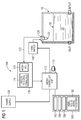
- Figure 1 shows a time-of-flight ranging or pulse-echo level measurement system 100 in accordance with the present invention.
- the pulse-echo level measurement system 100 is installed in a vessel 10, e.g. a storage tank, containing a material 20, for example, a liquid, sludge or granular material, having a level determined by the top surface of the material 20.
- a vessel e.g. a storage tank
- the top surface of the material 20 provides a reflective surface or reflector, indicated by reference 30, which reflects pulses, e.g. ultrasonic pulses or radar energy bursts emitted by a transducer.
- the pulse-echo level measurement system 100 includes a controller or signal processor unit 110, a transducer 120, a receiver module 130, a transmitter stage 140 and a power supply unit 150.
- the power supply 150 may be replaced by a loop powered interface (not shown).
- the controller 110 for example a microprocessor, executes a computer program, for example stored in program memory as firmware indicated by block 160.
- the computer program or firmware program module 160 provides the functionality associated with the level measurement operations and the digital interface and receiver as described in more detail below.
- the microprocessor 110 includes an oscillator 112 for establishing an accurate sampling time base.
- the receiver module 130 comprises an interface component or circuit 170.
- the firmware program module 160 includes a digital receive signal processing module 180.
- the firmware program module 160 includes a functional module 182 for controlling the transmitter stage 140 to emit energy (e.g. ultrasonic) pulses from the transducer 120, a communication interface module 184, and a user interface module 186.
- the digital receive signal processing module 180 may be implemented as a program component or module in the firmware module 160.
- the receiver module 130 has an input port 172 coupled to the output of the transducer 120.
- the receiver module 130 includes an analog-to-digital (A/D) converter 174.
- the A/D converter 174 converts the receive echo signals outputted by the transducer 120 into digital signals which are then processed by the digital receive signal processing module 180.
- the digital receive signal processing module 180 process the digitized receive echo signals to determine level measurements.
- the digital receive signal processing module 180 is implemented in firmware or software which is executed by the microprocessor 110, as described in more detail below.
- the digital receive signal processing module 180 comprises a separate microprocessor or microcontroller which performs some or all of the functions associated with the digital receive signal processing and then transfers or communicates these calculations or results to the microprocessor operating as the controller 110, i.e. a master slave arrangement.
- the buffer/amplifier stage 176 conditions and/or amplifies the electrical signals outputted by the transducer 120 and corresponding to the receive echo pulses, i.e. ultrasonic or radar pulses reflected by the surface 30 of the material 20 contained in the storage vessel 10.
- the buffer/amplifier stage 176 may comprise a buffer, i.e. a unity gain amplifier, and one or more other amplifiers (not shown) if the electrical signals from the transducer 120 are to be amplified.
- the conditioned/amplified signals outputted by the buffer/amplifier stage 176 are applied to the input port on the A/D converter 174. In a typical pulse-echo level measurement application, a dynamic range of about 100 dB is needed.
- the A/D converter 174 needs to be at least 17 bits wide.
- the A/D converter 174 should be fast enough to provide the required sample resolution.
- the A/D converter 174 may implemented using a single device or component (for example, a 20 bit wide device), or two or three A/D converters coupled together to provide +17 bits resolution and high speed conversion.
- the digitized output from the A/D converter 174 is inputted by the controller 110 and processed in the digital receive signal processing module 180 as will now be described in more detail below with reference to Fig. 3 .
- the buffer/memory stage 210 comprises a buffer implemented in on-chip memory or memory accessed by the microprocessor 110.
- the buffer/memory stage 210 may be implemented in firmware to provide partial memory buffering or full memory buffering of the digitized input data or signals 201. If partial memory buffering is utilized, then the remaining program modules or program functions 220 to 280 are executed in "real-time" by the microprocessor 110 ( Fig. 2 ). On the other hand, if full memory buffering is utilized and the digitized signals for an entire capture window are stored in memory, then the remaining program modules or functions 220 to 280 may be executed by the microprocessor 110 on a non real-time basis, for example, asynchronously or on a scheduled basis.
- Fig. 5 shows operation of the buffer/memory stage 210.
- the microcontroller 110 under firmware control executes a "shot setup" operation 501, i.e. controlling the transmitter stage 140 ( Fig. 1 ) and the transducer 120 ( Fig. 1 ) to emit energy (e.g. ultrasonic) pulses.
- the receive echo pulses are detected or received by the interface circuit 170 ( Fig. 1 ) and digitized by the A/D converter 174 ( Fig. 1 ) during an A/D sampling operation indicated by reference 502.
- the digitized sample is stored in memory during a capture sample to buffer operation indicated by reference 504.
- the digitization and capture operations 502, 504 are repeated until the receive echo pulse(s) corresponding to the transmit burst are digitized and stored in memory, or the memory buffer is filled, for example, using a partial memory buffering approach.
- a low pass filter operation 506 is applied to the data stored in the memory buffer as described in more detail below.
- the low pass filter stage 220 functions to filter the digitized receive signals digitized by the A/D converter 174 ( Fig. 1 ) and stored in the memory buffer.
- the low pass filter stage 220 applies a low pass filter operation to the digitized receive signals to minimize the effects of aliasing.
- the bandpass filter module 230 applies a bandpass filter function to the low pass filtered output from the low pass filter stage 220.
- the bandpass filter module 230 processes the low pass filtered digital samples with a center frequency corresponding to the operating frequency for the transducer 120 ( Fig. 1 ).
- the bandpass filtering together with the low pass filtering serve to reduce the noise in the digitized receive signals and to increase the signal-to-noise ratio (SNR) as high as possible, in order to facilitate the identification of valid echo pulses.
- the bandpass filter module 230 utilizes a Finite Impulse filter to obtain the desired frequency output.
- the envelope detection stage 240 processes the filtered digital samples after the bandpass filter stage 230.
- the envelope detection stage 240 is implemented to save only the positive envelope of the receive echo signals derived from the digital samples, as the peaks are sufficient to provide the required information for echo identification.
- the envelope detection stage 240 comprises an algorithm which takes and stores the digital samples corresponding to the peaks of the digitized receive echo signal.
- the operation of the logarithm amplifier stage 260 is applied.
- the resample stage 250 is applied to resample the detected envelope signal if not all the data samples in the envelope signal are required for the subsequent calculations.
- the logarithm stage 260 is included to compress the dynamic range of detected envelope signal (or resampled detected envelope signal if the resample operation is applied at stage 250). By compressing the detected envelope signal, a more useable or manageable form is provided for subsequent processing by the echo processing stage 280. In an exemplary implementation, the logarithm stage 260 compresses the digital samples for the envelope signal from 20 bits to 8 bits.
- the scaling stage 270 is provided to scale the digital samples so that the samples fall into a correct range for the algorithm(s) included in the echo processing stage 280.
- the echo processing stage 280 includes an algorithm for generating an echo profile, for example an echo profile 400 as depicted in Fig. 4 .
- the echo profile 400 comprises a half pulse 410 which corresponds to the ring down in the transducer 120 ( Fig. 1 ).
- the ring down comprises the period during which the transducer 120 is still ringing down from the transmit pulses emitted and as such it is very difficult to detect reflected energy pulses.
- the echo profile 400 comprises a number of pulses 430, 420a and 420b.
- the echo pulses 420a, 420b are identified as valid receive echo pulses, for example, by using a time varying threshold (TVT) curve 402.
- TVT time varying threshold
- the TVT curve 402 provides a baseline or line on the echo profile 400 which is above the noise level in the echo profile 400. Valid echoes appear above the TVT curve 402.
- Various algorithms and techniques are known in the art for the generating the TVT curve 402 and the particular implementation for the echo processing stage 280 will be within the understanding of one skilled in the art.
- Echo pulse(s) 420 falling below the TVT curve 402 are considered to comprise noise.
- the ring down period 410 also falls underneath the TVT curve 402 and is treated as noise.
- the echo processing module 280 includes an algorithm which uses the echo profile 400 to calculate the range, i.e. the distance to the reflective surface, from the time it takes for the reflected energy pulse to travel from the reflective surface to the transducer 120.
- the distance measurement 202 may be displayed on a display module (not shown) or transferred to a remote computer (not shown) using a communication link, for example, a 4-to-20 mA current loop (not shown).
- the controller or signal processor 110 is implemented using a microprocessor or microcontroller, which is suitably programmed to perform these operations and processing steps associated with the program modules or functions 210 to 280 described above.
- a microprocessor or microcontroller which is suitably programmed to perform these operations and processing steps associated with the program modules or functions 210 to 280 described above.
- the particular implementation of these program modules and other functions in software or firmware as described above will be within the understanding of those skilled in the art.
- the digital receive signal processing module 180 not only simplifies the circuit requirements for processing receive echo signals, but provides greater flexibility for processing the receive echo signals and facilitates future changes or functionality upgrades, for example, by replacing the firmware module 160 with new read only memory chip(s) or downloading the new firmware program module 160 to RAM program memory or non-volatile read/writable program memory.
Landscapes
- Physics & Mathematics (AREA)
- Engineering & Computer Science (AREA)
- Radar, Positioning & Navigation (AREA)
- Remote Sensing (AREA)
- General Physics & Mathematics (AREA)
- Electromagnetism (AREA)
- Thermal Sciences (AREA)
- Fluid Mechanics (AREA)
- Computer Networks & Wireless Communication (AREA)
- Acoustics & Sound (AREA)
- Measurement Of Velocity Or Position Using Acoustic Or Ultrasonic Waves (AREA)
- Measurement Of Levels Of Liquids Or Fluent Solid Materials (AREA)
Claims (4)
- Füllstandsmessgerät zum Messen eines Abstands zu einem Material (20) mit einer Oberfläche (30), wobei das Füllstandsmessgerät umfasst:einen Messwandler (120), der mit einem Sender (140) gekoppelt ist, um Energieimpulse auszusenden, und der ferner mit einem Empfängermodul (130) zum Empfangen der von der Oberfläche (30) des Materials (20) zurückgeworfenen Energieimpulse und zum Erzeugen eines Echosignals gekoppelt ist;wobei der Sender (140) und das Empfängermodul (130) mit einer Steuerung (110) gekoppelt sind, die unter der Kontrolle eines gespeicherten Programms arbeitet, wobei das gespeicherte Programm ein Empfangssignal-Verarbeitungsmodul (180) aufweist;wobei das kombinierte Empfängermodul (130) und Empfangssignal-Verarbeitungsmodul (180) Mittel für die Tiefpassfilterung und die Hüllkurvenerkennung der empfangenen Echosignale aufweisen,wobei das Empfängermodul (130) einen Analog/Digital-Wandler (174) aufweist; unddas Empfangssignal-Verarbeitungsmodul (180) eine Verarbeitungskomponente (280) aufweist, um basierend auf dem digitalisierten Echosignal nach Tiefpassfilterung und Hüllkurvenerkennung den Abstand zur Oberfläche des Materials (20) zu berechnen,dadurch gekennzeichnet,dass das Empfangssignal-Verarbeitungsmodul (180) zwischen dem Analog/Digital-Wandler (174) und der Verarbeitungskomponente (280) umfasst:eine Programmkomponente (210), die dafür ausgelegt ist, digitale Abtastwerte vom Analog/Digital-Wandler (174) in einem Speicher zwischenzuspeichern, der für die Steuerung (110) zugänglich ist;eine digitale Tiefpassfilter-Programmkomponente (220), die dafür ausgelegt ist, mehrere der zwischengespeicherten digitalen Abtastwerte einer Tiefpassfilterung zu unterziehen;eine Bandpassfilter-Programmkomponente (230), die dafür ausgelegt ist, mehrere der tiefpassgefilterten digitalen Abtastwerte einer Bandpassfilterung zu unterziehen, wobei der Messwandler (120) eine Betriebsfrequenz hat und das Bandpassfilter (230) eine der Betriebsfrequenz entsprechende Mittenfrequenz hat;eine digitale Hüllkurvenerkennungs-Programmkomponente (240), die dafür ausgelegt ist, positive Spitzen in den bandpassgefilterten digitalen Abtastwerten zu erkennen; undeine Datenkomprimierungs-Programmkomponente (260), die dafür ausgelegt ist, die digitalen Abtastwerte in der Hüllkurve in komprimierte digitale Abtastwerte umzuwandeln.
- Füllstandsmessgerät nach Anspruch 1, dadurch gekennzeichnet, dass das Empfangssignal-Verarbeitungsmodul (180) eine Neuabtast-Programmkomponente (250) aufweist, die dafür ausgelegt ist, digitale Abtastwerte in der erkannten Hüllkurve erneut abzutasten.
- Füllstandsmessgerät nach einem der vorstehenden Ansprüche, dadurch gekennzeichnet, dass die digitalen Abtastwerte in der Hüllkurve 20 Bits umfassen und dass die Datenkomprimierungs-Programmkomponente (260) dafür ausgelegt ist, die digitalen Abtastwerte in komprimierte digitale Abtastwerte mit 8 Bit umzuwandeln.
- Füllstandsmessgerät nach einem der vorstehenden Ansprüche, dadurch gekennzeichnet, dass das Empfangssignal-Verarbeitungsmodul (180) eine Skalier-Programmkomponente (270) aufweist, die dafür ausgelegt ist, einen Skalierfaktor auf die komprimierten digitalen Abtastwerte anzuwenden.
Applications Claiming Priority (1)
| Application Number | Priority Date | Filing Date | Title |
|---|---|---|---|
| US10/954,891 US7334470B1 (en) | 2004-09-30 | 2004-09-30 | Digital interface and receiver for time-of-flight level measurement and pulse-echo ranging systems |
Publications (3)
| Publication Number | Publication Date |
|---|---|
| EP1662237A2 EP1662237A2 (de) | 2006-05-31 |
| EP1662237A3 EP1662237A3 (de) | 2007-12-19 |
| EP1662237B1 true EP1662237B1 (de) | 2016-08-31 |
Family
ID=36102864
Family Applications (1)
| Application Number | Title | Priority Date | Filing Date |
|---|---|---|---|
| EP05109107.2A Ceased EP1662237B1 (de) | 2004-09-30 | 2005-09-30 | Füllstandsmessgerät |
Country Status (2)
| Country | Link |
|---|---|
| US (1) | US7334470B1 (de) |
| EP (1) | EP1662237B1 (de) |
Families Citing this family (21)
| Publication number | Priority date | Publication date | Assignee | Title |
|---|---|---|---|---|
| US7472593B2 (en) * | 2005-12-01 | 2009-01-06 | Cytyc Corporation | Fluid level regulator |
| US8100006B2 (en) * | 2006-08-21 | 2012-01-24 | Engineering Technologies Canada Ltd. | Liquid level measurement device and installation incorporating the same |
| EP1918735B1 (de) * | 2006-10-31 | 2009-08-26 | Siemens Milltronics Process Instruments Inc. | Verfahren zur Verarbeitung eines Echoprofils |
| US8746045B2 (en) | 2006-11-17 | 2014-06-10 | Meggitt (Orange County), Inc. | System and method for identifying fluids and monitoring fluid quality in a vessel |
| US8794063B2 (en) * | 2007-01-08 | 2014-08-05 | Meggitt (Orange County), Inc. | System and method for optimizing sweep delay and aliasing for time domain reflectometric measurement of liquid height within a tank |
| JP2010540942A (ja) | 2007-10-01 | 2010-12-24 | バイブロ−メーター インコーポレイテッド | 容器中の流体レベルを正確に測定するシステムおよび方法 |
| EP2116819B1 (de) * | 2008-05-09 | 2016-04-20 | Siemens Aktiengesellschaft | Radarbasiertes Verfahren zur Messung eines Materialstands in einem Behälter |
| DE102009001010B4 (de) * | 2008-12-30 | 2023-06-15 | Endress+Hauser SE+Co. KG | Verfahren zur Ermittlung und Überwachung des Füllstands eines Mediums in einem Behälter nach einem Laufzeitmessverfahren |
| US8220584B2 (en) * | 2009-05-18 | 2012-07-17 | Magnetrol International, Incorporated | Hybrid level measurement system |
| WO2011073366A1 (en) * | 2009-12-18 | 2011-06-23 | Total Petrochemicals Research Feluy | Method for monitoring the level of an ethylene polymerization catalyst slurry |
| EP2369362A1 (de) | 2010-03-18 | 2011-09-28 | Siemens Milltronics Process Instruments Inc. | Empfänger für ein Impulsechomesssystem mit digitalem polyphasem Dezimierungsfilter |
| EP2423707B1 (de) | 2010-08-25 | 2013-04-17 | Siemens Aktiengesellschaft | Verfahren zur Bestimmung des Echoabstands in einem akustischen Impulsechomesssystem |
| EP2442129B1 (de) * | 2010-10-18 | 2016-03-23 | Siemens Aktiengesellschaft | Verfahren zur Verarbeitung eines Echoamplitudenprofils, das durch ein Impulsechomesssystem erzeugt wird |
| DE102012107146A1 (de) * | 2012-08-03 | 2014-02-20 | Endress + Hauser Gmbh + Co. Kg | Verfahren zur Bestimmung und/oder Überwachung des Füllstands eines Mediums in einem Behälter |
| US9217660B2 (en) | 2013-01-30 | 2015-12-22 | A.P.M. Automation Solutions Ltd. | Surface mapping by virtual array processing via separate transmissions |
| DE102013103532A1 (de) * | 2013-04-09 | 2014-10-09 | Endress + Hauser Gmbh + Co. Kg | Verfahren zur Füllstandsmessung nach dem Laufzeitprinzip |
| WO2015182956A1 (en) | 2014-05-29 | 2015-12-03 | Samsung Electronics Co., Ltd. | Method and device for generating data representing structure of room |
| KR101939383B1 (ko) | 2016-10-18 | 2019-04-10 | 현대오트론 주식회사 | 초음파 센서 장치 및 초음파 센서 장치의 센싱 방법 |
| EP3401651B1 (de) * | 2017-05-09 | 2022-07-13 | VEGA Grieshaber KG | Grenzstandmessung, druckmessung oder durchflussmessung mit kurzer messzeit |
| CN110160602B (zh) * | 2018-02-11 | 2020-11-24 | 宁波方太厨具有限公司 | 一种吸油烟机的油杯液位测量方法 |
| CN115683284B (zh) * | 2022-12-29 | 2023-05-26 | 浙江和达科技股份有限公司 | 一种抑制虚假回波的方法及液位测量系统 |
Citations (1)
| Publication number | Priority date | Publication date | Assignee | Title |
|---|---|---|---|---|
| US20030146867A1 (en) * | 2001-12-28 | 2003-08-07 | Ralf Kornle | Apparatus and method for measuring the distance to an object |
Family Cites Families (8)
| Publication number | Priority date | Publication date | Assignee | Title |
|---|---|---|---|---|
| CA1214858A (en) * | 1984-09-27 | 1986-12-02 | Stanley Panton | Acoustic ranging system |
| US4853901A (en) * | 1986-02-18 | 1989-08-01 | Diagnostic Services, Inc. | Automatic liquid level recording device |
| US6621763B2 (en) * | 2001-07-23 | 2003-09-16 | Siemens Milltronics Process Instruments Inc. | Power saving technique for pulse-echo acoustic ranging systems |
| US6581460B1 (en) * | 2002-01-28 | 2003-06-24 | Vega Grieshaber Kg | Method and device for direct digitizing microwave signals |
| CA2405656A1 (en) * | 2002-09-27 | 2004-03-27 | Nigel Ashley Preston | Method for determining echo distance using autocorrelation |
| US6925870B2 (en) * | 2003-09-23 | 2005-08-09 | Battelle Memorial Institute | Ultrasonic fill level device and method |
| US7098669B2 (en) * | 2003-10-01 | 2006-08-29 | Flowline, Inc. | Depth determining system |
| US7010973B2 (en) * | 2004-03-19 | 2006-03-14 | Siemens Milltronics Process Instruments Inc. | Method and apparatus for improving accuracy in ultrasonic echo ranging systems |
-
2004
- 2004-09-30 US US10/954,891 patent/US7334470B1/en not_active Expired - Lifetime
-
2005
- 2005-09-30 EP EP05109107.2A patent/EP1662237B1/de not_active Ceased
Patent Citations (1)
| Publication number | Priority date | Publication date | Assignee | Title |
|---|---|---|---|---|
| US20030146867A1 (en) * | 2001-12-28 | 2003-08-07 | Ralf Kornle | Apparatus and method for measuring the distance to an object |
Also Published As
| Publication number | Publication date |
|---|---|
| US20080034863A1 (en) | 2008-02-14 |
| US7334470B1 (en) | 2008-02-26 |
| EP1662237A2 (de) | 2006-05-31 |
| EP1662237A3 (de) | 2007-12-19 |
Similar Documents
| Publication | Publication Date | Title |
|---|---|---|
| EP1662237B1 (de) | Füllstandsmessgerät | |
| US5226328A (en) | Velocity measurement system | |
| US5020374A (en) | Velocity measurement system | |
| US4596144A (en) | Acoustic ranging system | |
| US6295874B1 (en) | Apparatus for determining a physical process variable of a medium | |
| RU2166737C2 (ru) | Передатчик уровня | |
| US6305233B1 (en) | Digital speed determination in ultrasonic flow measurements | |
| US6678209B1 (en) | Apparatus and method for detecting sonar signals in a noisy environment | |
| US9001620B2 (en) | Method for echo processing in a pulse-echo ranging system | |
| US7672797B2 (en) | Flow measurement in partially filled pipes using pulsed peak velocity doppler | |
| MX2007010462A (es) | Sistema y metodo para medir el contenido de un deposito. | |
| KR20050014051A (ko) | 초음파 신호에서 주파수 분리를 이용한 거리측정 방법 및장치 | |
| WO2012004121A1 (en) | Calibration of a distance measuring device | |
| JP2774270B2 (ja) | パルス走行時間原理に従った距離測定の際の固定目標エコーの抑圧方法および装置 | |
| US10466209B2 (en) | Low-power wireless device for asset-integrity monitoring | |
| CN112912761A (zh) | 存在多普勒频移时的超声回波处理 | |
| US7039549B2 (en) | Sensor system and method, in particular for determining distances | |
| US12135231B2 (en) | Fill level radar with variable quantization accuracy | |
| EA005504B1 (ru) | Уровнемер, работающий на микроволнах | |
| CN102735314A (zh) | 一种高精度的外贴式超声液位计 | |
| US5036477A (en) | Method for the interference suppression in ultrasonic distance measurements | |
| RU2241242C1 (ru) | Эхолот | |
| CN105444840A (zh) | 一种超声波液位检测仪 | |
| US20050204812A1 (en) | Method and apparatus for improving accuracy in ultrasonic echo ranging systems | |
| KR100192637B1 (ko) | 초음파 센서의 최적 구동 주파수 탐지 장치 및 방법 |
Legal Events
| Date | Code | Title | Description |
|---|---|---|---|
| PUAI | Public reference made under article 153(3) epc to a published international application that has entered the european phase |
Free format text: ORIGINAL CODE: 0009012 |
|
| AK | Designated contracting states |
Kind code of ref document: A2 Designated state(s): AT BE BG CH CY CZ DE DK EE ES FI FR GB GR HU IE IS IT LI LT LU LV MC NL PL PT RO SE SI SK TR |
|
| AX | Request for extension of the european patent |
Extension state: AL BA HR MK YU |
|
| PUAL | Search report despatched |
Free format text: ORIGINAL CODE: 0009013 |
|
| AK | Designated contracting states |
Kind code of ref document: A3 Designated state(s): AT BE BG CH CY CZ DE DK EE ES FI FR GB GR HU IE IS IT LI LT LU LV MC NL PL PT RO SE SI SK TR |
|
| AX | Request for extension of the european patent |
Extension state: AL BA HR MK YU |
|
| 17P | Request for examination filed |
Effective date: 20080619 |
|
| AKX | Designation fees paid |
Designated state(s): DE FR GB |
|
| 17Q | First examination report despatched |
Effective date: 20080731 |
|
| RAP1 | Party data changed (applicant data changed or rights of an application transferred) |
Owner name: SIEMENS AKTIENGESELLSCHAFT |
|
| RAP1 | Party data changed (applicant data changed or rights of an application transferred) |
Owner name: SIEMENS AKTIENGESELLSCHAFT |
|
| RAP1 | Party data changed (applicant data changed or rights of an application transferred) |
Owner name: SIEMENS AKTIENGESELLSCHAFT |
|
| REG | Reference to a national code |
Ref country code: DE Ref legal event code: R079 Ref document number: 602005050104 Country of ref document: DE Free format text: PREVIOUS MAIN CLASS: G01F0023296000 Ipc: G01F0023284000 |
|
| GRAP | Despatch of communication of intention to grant a patent |
Free format text: ORIGINAL CODE: EPIDOSNIGR1 |
|
| RIC1 | Information provided on ipc code assigned before grant |
Ipc: G01F 23/296 20060101ALI20160310BHEP Ipc: G01S 13/10 20060101ALI20160310BHEP Ipc: G01F 23/284 20060101AFI20160310BHEP Ipc: G01S 15/10 20060101ALI20160310BHEP |
|
| INTG | Intention to grant announced |
Effective date: 20160324 |
|
| GRAS | Grant fee paid |
Free format text: ORIGINAL CODE: EPIDOSNIGR3 |
|
| GRAA | (expected) grant |
Free format text: ORIGINAL CODE: 0009210 |
|
| AK | Designated contracting states |
Kind code of ref document: B1 Designated state(s): DE FR GB |
|
| REG | Reference to a national code |
Ref country code: GB Ref legal event code: FG4D |
|
| REG | Reference to a national code |
Ref country code: FR Ref legal event code: PLFP Year of fee payment: 12 |
|
| REG | Reference to a national code |
Ref country code: DE Ref legal event code: R096 Ref document number: 602005050104 Country of ref document: DE |
|
| REG | Reference to a national code |
Ref country code: DE Ref legal event code: R097 Ref document number: 602005050104 Country of ref document: DE |
|
| PLBE | No opposition filed within time limit |
Free format text: ORIGINAL CODE: 0009261 |
|
| STAA | Information on the status of an ep patent application or granted ep patent |
Free format text: STATUS: NO OPPOSITION FILED WITHIN TIME LIMIT |
|
| 26N | No opposition filed |
Effective date: 20170601 |
|
| REG | Reference to a national code |
Ref country code: FR Ref legal event code: PLFP Year of fee payment: 13 |
|
| REG | Reference to a national code |
Ref country code: FR Ref legal event code: PLFP Year of fee payment: 14 |
|
| PGFP | Annual fee paid to national office [announced via postgrant information from national office to epo] |
Ref country code: GB Payment date: 20211004 Year of fee payment: 17 |
|
| PGFP | Annual fee paid to national office [announced via postgrant information from national office to epo] |
Ref country code: FR Payment date: 20220921 Year of fee payment: 18 |
|
| GBPC | Gb: european patent ceased through non-payment of renewal fee |
Effective date: 20220930 |
|
| PG25 | Lapsed in a contracting state [announced via postgrant information from national office to epo] |
Ref country code: GB Free format text: LAPSE BECAUSE OF NON-PAYMENT OF DUE FEES Effective date: 20220930 |
|
| PGFP | Annual fee paid to national office [announced via postgrant information from national office to epo] |
Ref country code: DE Payment date: 20231120 Year of fee payment: 19 |
|
| PG25 | Lapsed in a contracting state [announced via postgrant information from national office to epo] |
Ref country code: FR Free format text: LAPSE BECAUSE OF NON-PAYMENT OF DUE FEES Effective date: 20230930 |
|
| REG | Reference to a national code |
Ref country code: DE Ref legal event code: R119 Ref document number: 602005050104 Country of ref document: DE |
|
| PG25 | Lapsed in a contracting state [announced via postgrant information from national office to epo] |
Ref country code: DE Free format text: LAPSE BECAUSE OF NON-PAYMENT OF DUE FEES Effective date: 20250401 |