EP1662194A1 - Rotating stand - Google Patents
Rotating stand Download PDFInfo
- Publication number
- EP1662194A1 EP1662194A1 EP04772551A EP04772551A EP1662194A1 EP 1662194 A1 EP1662194 A1 EP 1662194A1 EP 04772551 A EP04772551 A EP 04772551A EP 04772551 A EP04772551 A EP 04772551A EP 1662194 A1 EP1662194 A1 EP 1662194A1
- Authority
- EP
- European Patent Office
- Prior art keywords
- gear
- disc
- equipment
- worm gear
- rotated
- Prior art date
- Legal status (The legal status is an assumption and is not a legal conclusion. Google has not performed a legal analysis and makes no representation as to the accuracy of the status listed.)
- Granted
Links
Images


Classifications
-
- F—MECHANICAL ENGINEERING; LIGHTING; HEATING; WEAPONS; BLASTING
- F16—ENGINEERING ELEMENTS AND UNITS; GENERAL MEASURES FOR PRODUCING AND MAINTAINING EFFECTIVE FUNCTIONING OF MACHINES OR INSTALLATIONS; THERMAL INSULATION IN GENERAL
- F16M—FRAMES, CASINGS OR BEDS OF ENGINES, MACHINES OR APPARATUS, NOT SPECIFIC TO ENGINES, MACHINES OR APPARATUS PROVIDED FOR ELSEWHERE; STANDS; SUPPORTS
- F16M11/00—Stands or trestles as supports for apparatus or articles placed thereon ; Stands for scientific apparatus such as gravitational force meters
- F16M11/20—Undercarriages with or without wheels
- F16M11/22—Undercarriages with or without wheels with approximately constant height, e.g. with constant length of column or of legs
-
- F—MECHANICAL ENGINEERING; LIGHTING; HEATING; WEAPONS; BLASTING
- F16—ENGINEERING ELEMENTS AND UNITS; GENERAL MEASURES FOR PRODUCING AND MAINTAINING EFFECTIVE FUNCTIONING OF MACHINES OR INSTALLATIONS; THERMAL INSULATION IN GENERAL
- F16M—FRAMES, CASINGS OR BEDS OF ENGINES, MACHINES OR APPARATUS, NOT SPECIFIC TO ENGINES, MACHINES OR APPARATUS PROVIDED FOR ELSEWHERE; STANDS; SUPPORTS
- F16M11/00—Stands or trestles as supports for apparatus or articles placed thereon ; Stands for scientific apparatus such as gravitational force meters
- F16M11/02—Heads
- F16M11/04—Means for attachment of apparatus; Means allowing adjustment of the apparatus relatively to the stand
- F16M11/06—Means for attachment of apparatus; Means allowing adjustment of the apparatus relatively to the stand allowing pivoting
- F16M11/08—Means for attachment of apparatus; Means allowing adjustment of the apparatus relatively to the stand allowing pivoting around a vertical axis, e.g. panoramic heads
-
- F—MECHANICAL ENGINEERING; LIGHTING; HEATING; WEAPONS; BLASTING
- F16—ENGINEERING ELEMENTS AND UNITS; GENERAL MEASURES FOR PRODUCING AND MAINTAINING EFFECTIVE FUNCTIONING OF MACHINES OR INSTALLATIONS; THERMAL INSULATION IN GENERAL
- F16M—FRAMES, CASINGS OR BEDS OF ENGINES, MACHINES OR APPARATUS, NOT SPECIFIC TO ENGINES, MACHINES OR APPARATUS PROVIDED FOR ELSEWHERE; STANDS; SUPPORTS
- F16M11/00—Stands or trestles as supports for apparatus or articles placed thereon ; Stands for scientific apparatus such as gravitational force meters
- F16M11/02—Heads
- F16M11/18—Heads with mechanism for moving the apparatus relatively to the stand
-
- F—MECHANICAL ENGINEERING; LIGHTING; HEATING; WEAPONS; BLASTING
- F16—ENGINEERING ELEMENTS AND UNITS; GENERAL MEASURES FOR PRODUCING AND MAINTAINING EFFECTIVE FUNCTIONING OF MACHINES OR INSTALLATIONS; THERMAL INSULATION IN GENERAL
- F16M—FRAMES, CASINGS OR BEDS OF ENGINES, MACHINES OR APPARATUS, NOT SPECIFIC TO ENGINES, MACHINES OR APPARATUS PROVIDED FOR ELSEWHERE; STANDS; SUPPORTS
- F16M2200/00—Details of stands or supports
- F16M2200/08—Foot or support base
-
- Y—GENERAL TAGGING OF NEW TECHNOLOGICAL DEVELOPMENTS; GENERAL TAGGING OF CROSS-SECTIONAL TECHNOLOGIES SPANNING OVER SEVERAL SECTIONS OF THE IPC; TECHNICAL SUBJECTS COVERED BY FORMER USPC CROSS-REFERENCE ART COLLECTIONS [XRACs] AND DIGESTS
- Y10—TECHNICAL SUBJECTS COVERED BY FORMER USPC
- Y10S—TECHNICAL SUBJECTS COVERED BY FORMER USPC CROSS-REFERENCE ART COLLECTIONS [XRACs] AND DIGESTS
- Y10S248/00—Supports
- Y10S248/917—Video display screen support
-
- Y—GENERAL TAGGING OF NEW TECHNOLOGICAL DEVELOPMENTS; GENERAL TAGGING OF CROSS-SECTIONAL TECHNOLOGIES SPANNING OVER SEVERAL SECTIONS OF THE IPC; TECHNICAL SUBJECTS COVERED BY FORMER USPC CROSS-REFERENCE ART COLLECTIONS [XRACs] AND DIGESTS
- Y10—TECHNICAL SUBJECTS COVERED BY FORMER USPC
- Y10S—TECHNICAL SUBJECTS COVERED BY FORMER USPC CROSS-REFERENCE ART COLLECTIONS [XRACs] AND DIGESTS
- Y10S248/00—Supports
- Y10S248/917—Video display screen support
- Y10S248/919—Adjustably orientable video screen support
- Y10S248/922—Angular
Definitions
- the present invention relates to a swivel stand which turns equipment, such as a TV monitor or monitor camera, electrically or manually.
- a cabinet provided with a TV monitor is supported by a stand in a rotatable fashion. Furthermore, the rotational driving power generated by the rotation axis of an electric motor is transmitted to a base through both a gear and a gear unit composed of a worm wheel mating with the gear and large and small gears. Therefore, the forward/reverse rotation of the electric motor allows a cabinet to be turned clockwise or counterclockwise.
- the above swivel stand of the background art is configured to be rotated electrically, and cannot be rotated manually.
- An object of the present invention is to provide a simple swivel stand in which an electric or manual rotation can be used arbitrarily.
- the present invention for overcoming the above disadvantage is directed to a swivel stand, and this swivel stand is characterized by including:
- the swivel stand is provided with a mechanism by which while the equipment such as a TV monitor or monitor camera is rotated manually, the rotation of the equipment is controlled such that the disc fixed by the worm gear slides on the pole joined to the equipment, or by which while the equipment is rotated by the motor, the rotation of the equipment is controlled such that the disc rotated by the worm gear synchronizes the pole joined to the rotatable equipment. Consequently, it is possible for the swivel stand to use an electric and manual drives in combination by employing the simple structure. In addition, since the number of the components is made small, the reliability is improved.
- the gear may be fitted into or mate with a circumference of the disc.
- the present invention is characterized in that the disc and the gear are integrally molded.
- the present invention it is possible to switch the electric and manual operational states through the disc and the gear that are integrally molded.
- the electric and manual drive can be used in combination by employing the simple structure.
- the present invention is characterized in that the support member is a pole joined to the equipment, and a bush is secured to the pole, thereby decreasing the sliding resistance between the equipment and the disc upon manual rotation of the equipment.
- the bush is fixed to the pole to thereby decrease the sliding resistance between the equipment and the disc, the equipment can be rotated smoothly upon manual rotation of the equipment. This makes it possible to improve the usability.
- the present invention is characterized in that the disc has a hollow, doughnut shape, the gear is provided on an inner circumference of the disc, and the electric motor and the worm gear are arranged within a hollow portion of the disc.
- the individual components of the swivel stand can be arranged space-efficiently.
- the present invention is characterized in that at least one reduction gear is placed between the gear and the worm gear, and the reduction gear mates with them.
- Fig. 1 is an exploded configuration view for explaining a swivel stand according to a first embodiment of the present invention.
- reference numerals 1, 2, 3, 4, 5, 6, 7, 8, 9 and 10 denote a TV monitor, pole, bush, disc, gear, thrust bearing, base, worm gear, motor and controller, respectively.
- the TV monitor 1 such as a plasma display or liquid crystal display, which is installed as equipment, is supported in such a way to rotate around the pole 2 joined to a housing and with respect to the base 7.
- the pole 2 is one example of a support member for supporting the equipment.
- the bush 3 is fixed to the pole 2 and is used to decrease the sliding resistance to the disc 4 upon manual rotation.
- the disc 4 is mounted on the base 7 in a rotatable fashion.
- This disc employs two-piece-structure, because the gear 5 is attached to the circumference of the disc 4.
- the disc 4 and the gear 5 may be integrated, but if they have the two-piece-structure, then both the strength necessary for the disc 4 and the productivity of the gear 5 can be attained.
- the disc 4 is formed by resin integrated molding, casting or multi-peace press. Since the disc 4 is used to block power generated in the reverse direction, an appropriate fabrication is selected based on required conditions such as its overall cost, weight or strength.
- the gear 5 is formed from resin molding.
- a single stage reduction gear is employed.
- multiple gears may be arranged between the gear 5 and the worm gear 8.
- a gear unit may be employed.
- the torque of the motor 9 and the rotational speed of the TV monitor 1 are adjustable. As a result, a significant effect can be produced although the number of the components increases.
- the thrust bearing 6 made of resin or metal is provided, and it is configured to be supported by the pole 2.
- the disc 4 fixed by the worm gear 8 slides on the pole 2 joined to the TV monitor 1, so that the rotation is controlled.
- the disc 4 rotated by the worm gear 8 and the pole 2 joined to the TV monitor 1 rotate in synchronization with each other, so that the rotation is controlled.
- the TV monitor 1 is turned by the motor 9, the TV monitor 1 is caught by something or the rotation is hindered by a hand, in other words, the rotation of the TV monitor 1 is forced to stop. In this case, a slip motion is generated between the disc 4 and the base 7 similar to the behavior of the manual rotation, thereby preventing the motor from being damaged.
- the movement of the TV monitor 1 may be controlled by the controller 10. This enables the TV monitor 1 to return to a front or initial position from any given position instantly.
- the equipment to be rotated is not limited to the TV monitor 1. Alternatively, it may be a monitor camera.
- the swivel stand can function as one used for various equipment that will be rotated.
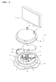
- Fig. 2 is an exploded configuration view for explaining a swivel stand according to a second embodiment of the present invention.
- Fig. 2 except for components in the following description, the same reference numerals are given to the same parts shown in Fig. 1, and duplicate description therefore is omitted.
- reference numerals 1, 2 and 4 denote a TV monitor, poles and disc, respectively.
- Reference numerals 5, 11 and 12 denote individual gears, respectively.
- Reference numerals 6, 7, 8, 9, 10, 13, 14 and 15 denote a thrust bearing, base, worm gear, motor, controller, middle cap, outer cap and support member, respectively.
- the support member 15 is composed of the poles 2 and the outer cap 14. While the TV monitor 1 is turned manually, the disc 4 fixed to the worm gear 8 slides on the support member 15, so that the rotation is controlled. In addition, while the TV monitor 1 is rotated by the motor 9, the disc 4 rotated by the worm gear 8 synchronizes the support member 15, so that the rotation is controlled. In this way, in this embodiment, the electric and manual rotations of the equipment, which is an object to be rotated, can be used in combination. These rotations are switched as necessary, thereby improving the usability.
- the disc 4 is a doughnut-shaped disc having a hole in its center, and the gear 5 is provided in the inner circumference of the disc 4.
- the motor 9 and the worm gear 8 are provided in a hollow portion 16 of the disc 4.
- the hollow portion 16 is a hollow space at the center of the disc 4.
- the gears 11 and 12 are arranged between the gear 5 and the worm gear 8. These gears 11 and 12 receive power of the motor 9 through the worm gear 8 and transmit it to the gear 5. With this configuration, the motor 9 and the worm gear 8 can be arranged space-efficiently.
- the middle cap 13 is a cover to wrap the motor 8, the worm gear 9 and the gears 11 and 12 from above.
- the middle cap 13 supports, for example, the rotation axis of the gears 11 and 12 from above in a rotatable fashion.
- the outer cap 14 has substantially the same diameter as that of the disc 4, and it covers the whole of the disc 4 from above. With this configuration, the motor 9, the worm gear 8 and the like that are provided within the hollow portion of the disc 4 can be protected favorably. Furthermore, since the diameter of the support member 15 including the outer cap 14 is large, the TV monitor 1 can be supported with stability.
- Fig. 3 is a view depicting a mating state of a worm gear 8 and gears 5, 11 and 12.
- the gears 11 and 12 serve as reduction gears, and each of them includes two, large and small pinions.
- the large pinion of the gear 11 mates with the worm gear 8, and rotates in conjunction with the worm gear 8.
- the small pinion of the gear 11 rotates in synchronization with the large pinion.
- the large pinion of the gear 12 mates with the small pinion of the gear 11, and rotates in conjunction with the small pinion of the gear 11. Furthermore, the small pinion of the gear 12 mates with the gear 5, and rotates in conjunction with the large pinion to thereby transmit power to the gear 5. With this configuration, the power generated by the motor 9 (see Fig. 2) is delivered to the gear 5 appropriately, and the disc 6 provided with the gear 5 thus rotates correctly.
- equipment which is an object to be rotated
- the operation is switched as necessary, so that the operationality is enhanced.
- the present invention can be realized with a simple structure and a small number of components. This contributes to the reduction in weight and cost. Even if the breakage occur, it is easy to determine its cause, thus leading to the improvement of the reliability.
- the present invention is applicable to a swivel stand appropriately which turns equipment, such as a TV monitor or monitor camera, electrically or manually.
Landscapes
- Engineering & Computer Science (AREA)
- General Engineering & Computer Science (AREA)
- Mechanical Engineering (AREA)
- Gear Transmission (AREA)
- Accessories Of Cameras (AREA)
- Gears, Cams (AREA)
- Devices For Indicating Variable Information By Combining Individual Elements (AREA)
- Ultra Sonic Daignosis Equipment (AREA)
- Vehicle Body Suspensions (AREA)
- Telephone Function (AREA)
Abstract
Description
- The present invention relates to a swivel stand which turns equipment, such as a TV monitor or monitor camera, electrically or manually.
- Known is a swivel stand in which a display or monitor camera to be turned is supported by an electric motor in a rotatable fashion (see Japanese Unexamined Patent Application Publications H9-18748, H7-203335 and H1-73876).
- For example, according to the disclosure of JP H7-203335, a cabinet provided with a TV monitor is supported by a stand in a rotatable fashion. Furthermore, the rotational driving power generated by the rotation axis of an electric motor is transmitted to a base through both a gear and a gear unit composed of a worm wheel mating with the gear and large and small gears. Therefore, the forward/reverse rotation of the electric motor allows a cabinet to be turned clockwise or counterclockwise.
- The above swivel stand of the background art is configured to be rotated electrically, and cannot be rotated manually.
- However, in actual use of the above swivel stand, there are sometimes occasions when a remote controller by which a TV monitor faces in any directions is missing or when a viewer wants a nearby person to change the orientation of the TV monitor manually.
- In this case, the above swivel stand of the background art cannot deal with the occasions, or either a complex clutch mechanism or controller is necessary, thus leading to the increase in the weight. In addition, the number of the components is made greater, thereby increasing costs or deteriorating the reliability.
- The present invention has been conceived in consideration of the above description. An object of the present invention is to provide a simple swivel stand in which an electric or manual rotation can be used arbitrarily.
- The present invention for overcoming the above disadvantage is directed to a swivel stand, and this swivel stand is characterized by including:
- a base;
- a disc being supported by the base in a rotatable fashion;
- a gear being provided on a circumference of the disc; and
- a worm gear mating with the gear, the worm gear to be rotated by an electric motor,
- wherein while the equipment is rotated manually, the disc fixed by the worm gear slides on the support member supporting the equipment, so that a rotation of the equipment is controlled, and
- wherein while the equipment is rotated by the electric motor, the disc rotated by the worm gear synchronizes the support member, so that a rotation of the equipment is controlled.
- In the present invention, the swivel stand is provided with a mechanism by which while the equipment such as a TV monitor or monitor camera is rotated manually, the rotation of the equipment is controlled such that the disc fixed by the worm gear slides on the pole joined to the equipment, or by which while the equipment is rotated by the motor, the rotation of the equipment is controlled such that the disc rotated by the worm gear synchronizes the pole joined to the rotatable equipment. Consequently, it is possible for the swivel stand to use an electric and manual drives in combination by employing the simple structure. In addition, since the number of the components is made small, the reliability is improved. The gear may be fitted into or mate with a circumference of the disc.
- Furthermore, the present invention is characterized in that the disc and the gear are integrally molded. In the present invention, it is possible to switch the electric and manual operational states through the disc and the gear that are integrally molded. As a result, the electric and manual drive can be used in combination by employing the simple structure.
- Moreover, the present invention is characterized in that the support member is a pole joined to the equipment, and a bush is secured to the pole, thereby decreasing the sliding resistance between the equipment and the disc upon manual rotation of the equipment.
- In the present invention, since the bush is fixed to the pole to thereby decrease the sliding resistance between the equipment and the disc, the equipment can be rotated smoothly upon manual rotation of the equipment. This makes it possible to improve the usability.
- The present invention is characterized in that the disc has a hollow, doughnut shape, the gear is provided on an inner circumference of the disc, and the electric motor and the worm gear are arranged within a hollow portion of the disc. In the present invention, the individual components of the swivel stand can be arranged space-efficiently.
- Furthermore, the present invention is characterized in that at least one reduction gear is placed between the gear and the worm gear, and the reduction gear mates with them.
- In the present invention, it is possible to adjust the torque or rotational speed of the electric motor by varying the size or the number of the reduction gear.
-
- Fig. 1 is an exploded configuration view for explaining a swivel stand according to a first embodiment of the present invention;
- Fig. 2 is an exploded configuration view for explaining a swivel stand according to a second embodiment of the present invention; and
- Fig. 3 is a view depicting a mating state of a
worm gear 8 andgears - Fig. 1 is an exploded configuration view for explaining a swivel stand according to a first embodiment of the present invention.
- In Fig. 1,
reference numerals - In the embodiments according to the present invention, the
TV monitor 1 such as a plasma display or liquid crystal display, which is installed as equipment, is supported in such a way to rotate around thepole 2 joined to a housing and with respect to thebase 7. Thepole 2 is one example of a support member for supporting the equipment. - The
bush 3 is fixed to thepole 2 and is used to decrease the sliding resistance to thedisc 4 upon manual rotation. - The
disc 4 is mounted on thebase 7 in a rotatable fashion. This disc employs two-piece-structure, because thegear 5 is attached to the circumference of thedisc 4. Alternatively, thedisc 4 and thegear 5 may be integrated, but if they have the two-piece-structure, then both the strength necessary for thedisc 4 and the productivity of thegear 5 can be attained. - The
disc 4 is formed by resin integrated molding, casting or multi-peace press. Since thedisc 4 is used to block power generated in the reverse direction, an appropriate fabrication is selected based on required conditions such as its overall cost, weight or strength. Thegear 5 is formed from resin molding. - The
worm gear 8, which is coupled directly to themotor 9 mounted on thebase 7, mates with thegear 5, and is rotated by themotor 9. - In this embodiment, there are no gears between the
gear 5 and theworm gear 8. In other words, a single stage reduction gear is employed. However, multiple gears may be arranged between thegear 5 and theworm gear 8. Specifically, a gear unit may be employed. In this case, the torque of themotor 9 and the rotational speed of theTV monitor 1 are adjustable. As a result, a significant effect can be produced although the number of the components increases. - Between the
disc 4 and thebase 7, the thrust bearing 6 made of resin or metal is provided, and it is configured to be supported by thepole 2. - Now, a description will be given, of a mechanism by which the
TV monitor 1 is turned in combination with electric and manual operations. - While the
TV monitor 1 is turned manually, thedisc 4 fixed by theworm gear 8 slides on thepole 2 joined to theTV monitor 1, so that the rotation is controlled. In addition, while theTV monitor 1 is turned by themotor 9, thedisc 4 rotated by theworm gear 8 and thepole 2 joined to theTV monitor 1 rotate in synchronization with each other, so that the rotation is controlled. - In this way, the operation of the
motor 9 and the manual operation can be used separately, thus achieving the combination of electric and manual rotations. - It is assumed that while the
TV monitor 1 is turned by themotor 9, theTV monitor 1 is caught by something or the rotation is hindered by a hand, in other words, the rotation of theTV monitor 1 is forced to stop. In this case, a slip motion is generated between thedisc 4 and thebase 7 similar to the behavior of the manual rotation, thereby preventing the motor from being damaged. Moreover, by installing a sensor on thebase 7, the movement of theTV monitor 1 may be controlled by thecontroller 10. This enables theTV monitor 1 to return to a front or initial position from any given position instantly. The equipment to be rotated is not limited to theTV monitor 1. Alternatively, it may be a monitor camera. Thus, the swivel stand can function as one used for various equipment that will be rotated. - Fig. 2 is an exploded configuration view for explaining a swivel stand according to a second embodiment of the present invention. In Fig. 2, except for components in the following description, the same reference numerals are given to the same parts shown in Fig. 1, and duplicate description therefore is omitted.
- In Fig. 2,
reference numerals Reference numerals Reference numerals - In this embodiment, the
support member 15 is composed of thepoles 2 and theouter cap 14. While theTV monitor 1 is turned manually, thedisc 4 fixed to theworm gear 8 slides on thesupport member 15, so that the rotation is controlled. In addition, while theTV monitor 1 is rotated by themotor 9, thedisc 4 rotated by theworm gear 8 synchronizes thesupport member 15, so that the rotation is controlled. In this way, in this embodiment, the electric and manual rotations of the equipment, which is an object to be rotated, can be used in combination. These rotations are switched as necessary, thereby improving the usability. - The
disc 4 is a doughnut-shaped disc having a hole in its center, and thegear 5 is provided in the inner circumference of thedisc 4. Themotor 9 and theworm gear 8 are provided in ahollow portion 16 of thedisc 4. Thehollow portion 16 is a hollow space at the center of thedisc 4. - The
gears gear 5 and theworm gear 8. These gears 11 and 12 receive power of themotor 9 through theworm gear 8 and transmit it to thegear 5. With this configuration, themotor 9 and theworm gear 8 can be arranged space-efficiently. - The
middle cap 13 is a cover to wrap themotor 8, theworm gear 9 and thegears middle cap 13 supports, for example, the rotation axis of thegears outer cap 14 has substantially the same diameter as that of thedisc 4, and it covers the whole of thedisc 4 from above. With this configuration, themotor 9, theworm gear 8 and the like that are provided within the hollow portion of thedisc 4 can be protected favorably. Furthermore, since the diameter of thesupport member 15 including theouter cap 14 is large, theTV monitor 1 can be supported with stability. - Fig. 3 is a view depicting a mating state of a
worm gear 8 and gears 5, 11 and 12. - In the embodiments, the
gears gear 11 mates with theworm gear 8, and rotates in conjunction with theworm gear 8. In addition, the small pinion of thegear 11 rotates in synchronization with the large pinion. - The large pinion of the
gear 12 mates with the small pinion of thegear 11, and rotates in conjunction with the small pinion of thegear 11. Furthermore, the small pinion of thegear 12 mates with thegear 5, and rotates in conjunction with the large pinion to thereby transmit power to thegear 5. With this configuration, the power generated by the motor 9 (see Fig. 2) is delivered to thegear 5 appropriately, and thedisc 6 provided with thegear 5 thus rotates correctly. - As described above, according to the present invention, equipment, which is an object to be rotated, can be rotated in combination of electric and manual operations. Accordingly, the operation is switched as necessary, so that the operationality is enhanced. Moreover, the present invention can be realized with a simple structure and a small number of components. This contributes to the reduction in weight and cost. Even if the breakage occur, it is easy to determine its cause, thus leading to the improvement of the reliability.
- Furthermore, by applying the two-piece-structure to the disc and the gear, both the strength necessary for the disc and the productivity of the gear can be satisfied.
- The present invention is applicable to a swivel stand appropriately which turns equipment, such as a TV monitor or monitor camera, electrically or manually.
Claims (5)
- A swivel stand for turning equipment, comprising:a base;a disc being supported by the base in a rotatable fashion;a gear being provided on a circumference of the disc; anda worm gear mating with the gear, the worm gear to be rotated by an electric motor,wherein while the equipment is turned manually, the disc fixed by the worm gear slides on the support member supporting the equipment, so that a rotation of the equipment is controlled, andwherein while the equipment is rotated by the electric motor, the disc rotated by the worm gear synchronizes the support member, so that a rotation of the equipment is controlled.
- The swivel stand according to claim 1,
wherein the disc and the gear are integrally molded. - The swivel stand according to claim 1 or 2,
wherein the support member is a pole being joined to the equipment, and
wherein a bush is fixed to the pole to thereby decrease a sliding resistance between the equipment and the disc, which is generated upon the manual rotation of the equipment. - The swivel stand according to claim 1 or 2,
wherein the disc has a hollow, doughnut shape,
wherein the gear is provided on an inner circumference of the disc, and
wherein the electric motor and the worm gear are arranged within a hollow portion of the disc. - The swivel stand according to one of claims 1 to 4, further comprising at least one reduction gear being provided between the gear and the worm gear, the reduction gear mating with the gear and the worm gear.
Applications Claiming Priority (2)
| Application Number | Priority Date | Filing Date | Title |
|---|---|---|---|
| JP2003209817 | 2003-08-29 | ||
| PCT/JP2004/012595 WO2005022024A1 (en) | 2003-08-29 | 2004-08-25 | Rotating stand |
Publications (3)
| Publication Number | Publication Date |
|---|---|
| EP1662194A1 true EP1662194A1 (en) | 2006-05-31 |
| EP1662194A4 EP1662194A4 (en) | 2006-09-20 |
| EP1662194B1 EP1662194B1 (en) | 2009-03-18 |
Family
ID=34263974
Family Applications (1)
| Application Number | Title | Priority Date | Filing Date |
|---|---|---|---|
| EP04772551A Expired - Lifetime EP1662194B1 (en) | 2003-08-29 | 2004-08-25 | Rotating stand |
Country Status (7)
| Country | Link |
|---|---|
| US (1) | US7677517B2 (en) |
| EP (1) | EP1662194B1 (en) |
| JP (1) | JP4394646B2 (en) |
| CN (1) | CN100427820C (en) |
| AT (1) | ATE426128T1 (en) |
| DE (1) | DE602004020075D1 (en) |
| WO (1) | WO2005022024A1 (en) |
Cited By (9)
| Publication number | Priority date | Publication date | Assignee | Title |
|---|---|---|---|---|
| EP1808635A3 (en) * | 2006-01-16 | 2007-08-08 | Samsung Electro-mechanics Co., Ltd | Display rotation apparatus |
| WO2008092457A1 (en) * | 2007-02-02 | 2008-08-07 | Bang & Olufsen A/S | Support for multimedia units |
| EP1850053A3 (en) * | 2006-04-27 | 2009-09-09 | Funai Electric Co., Ltd. | Swivel device and display apparatus equipped with the same |
| CN100568399C (en) * | 2006-09-14 | 2009-12-09 | 友达光电股份有限公司 | Positioning device, stepless rotary positioning device and display device with stepless rotary positioning device |
| CN101090003B (en) * | 2006-03-31 | 2011-01-19 | 下西技研工业株式会社 | Rotating device for flat display |
| US8091842B2 (en) * | 2004-11-18 | 2012-01-10 | Nigel Geoffrey Thomas | Automatically varying equipment support |
| CN104132225A (en) * | 2014-08-01 | 2014-11-05 | 福建中澳科技有限公司 | Adjustable displayer support |
| CN110332431A (en) * | 2019-06-12 | 2019-10-15 | 深圳创维-Rgb电子有限公司 | Display base and display |
| US20220049812A1 (en) * | 2020-08-12 | 2022-02-17 | Syncmold Enterprise Corp. | Supporting device |
Families Citing this family (37)
| Publication number | Priority date | Publication date | Assignee | Title |
|---|---|---|---|---|
| DE202006000785U1 (en) * | 2006-01-19 | 2007-05-24 | Jahnke Gmbh & Co. Kg | Electrically powered turntable |
| KR20070082797A (en) * | 2006-02-17 | 2007-08-22 | 엘지전자 주식회사 | Display stand |
| JP4893086B2 (en) * | 2006-04-26 | 2012-03-07 | 船井電機株式会社 | Display device |
| JP2008040288A (en) * | 2006-08-09 | 2008-02-21 | Shimonishi Giken Kogyo Kk | Flat display drive apparatus |
| JP4876833B2 (en) * | 2006-10-10 | 2012-02-15 | 船井電機株式会社 | Display device base including torque limiter device and torque limiter device |
| JP2008111497A (en) * | 2006-10-31 | 2008-05-15 | Shimonishi Giken Kogyo Kk | Motor driven swivel device |
| JP4222410B2 (en) * | 2006-11-07 | 2009-02-12 | 船井電機株式会社 | Display screen turning device |
| CN200989940Y (en) * | 2006-11-28 | 2007-12-12 | 周全 | GPS signal receiver support |
| US7854415B2 (en) * | 2006-12-04 | 2010-12-21 | Peerless Industries, Inc. | Motorized support for a television or other electronic display |
| JP4265676B2 (en) * | 2007-05-15 | 2009-05-20 | 船井電機株式会社 | Television equipment |
| ATE546685T1 (en) * | 2007-12-21 | 2012-03-15 | Fiedler Innovations Internat Ab | ADJUSTABLE MOTORIZED SCREEN MOUNT |
| JP2009175426A (en) * | 2008-01-24 | 2009-08-06 | Funai Electric Co Ltd | Image projector and optical axis adjusting method for the projector |
| JP5241308B2 (en) * | 2008-05-02 | 2013-07-17 | 三菱電機株式会社 | Turntable for display device |
| JP4530075B2 (en) * | 2008-05-07 | 2010-08-25 | 船井電機株式会社 | Display screen turning device and television device |
| TWM365047U (en) * | 2009-02-04 | 2009-09-11 | Syncmold Entpr Corp | Supporting frame |
| JP5241586B2 (en) * | 2009-04-08 | 2013-07-17 | 三菱電機株式会社 | Turntable for display device |
| CA2747647A1 (en) * | 2010-07-28 | 2012-01-28 | Jerry Moscovitch | Monitor stand allowing various types of motion |
| CN102518921A (en) * | 2011-12-23 | 2012-06-27 | 江门市圆美道科技有限公司 | Rotary seat |
| WO2014002395A1 (en) * | 2012-06-29 | 2014-01-03 | Oda Tadashi | Electrically driven support base |
| WO2014092869A1 (en) * | 2012-12-10 | 2014-06-19 | Utc Fire & Security Corporation | Alignment swivel and method |
| US9217537B2 (en) | 2013-05-16 | 2015-12-22 | Matthew R. Steubing | Mobile camera point of view mount |
| KR101387237B1 (en) * | 2013-06-18 | 2014-04-21 | 이판기 | Rotary device in engine stand for training |
| CN104653967B (en) * | 2014-12-24 | 2017-07-18 | 广西大学 | A kind of rotatable bogey |
| KR20160121652A (en) * | 2015-04-09 | 2016-10-20 | 삼성디스플레이 주식회사 | Display apparatus |
| KR20170030809A (en) | 2015-09-10 | 2017-03-20 | 삼성전자주식회사 | Display apparatus and control method thereof |
| KR102270693B1 (en) | 2016-12-23 | 2021-06-30 | 삼성전자주식회사 | Stand for display and display apparatus having the same |
| WO2018117772A1 (en) * | 2016-12-23 | 2018-06-28 | 삼성전자 주식회사 | Display stand and display device comprising same |
| CN107131407A (en) * | 2017-05-23 | 2017-09-05 | 中国科学院寒区旱区环境与工程研究所 | A kind of support and tower crane equipment |
| CN109099279B (en) * | 2018-09-25 | 2020-04-03 | 管浩铭 | Rotatable traffic monitoring camera installing support |
| CN109732901A (en) * | 2019-02-15 | 2019-05-10 | 上海幂方电子科技有限公司 | A kind of device for the automatic corner improving printing precision |
| WO2020243575A1 (en) | 2019-05-31 | 2020-12-03 | Touchstone Home Products, Inc. | Lift for television or other visual display screen |
| CN110375166A (en) * | 2019-06-26 | 2019-10-25 | 苏州金螳螂怡和科技有限公司 | A kind of pedestrian's bayonet capturing system |
| CN110908220B (en) * | 2019-11-30 | 2025-01-14 | 陈鸿刚 | A portable photography studio |
| TW202124871A (en) * | 2019-12-17 | 2021-07-01 | 香港商冠捷投資有限公司 | Display device |
| US11682869B1 (en) * | 2022-01-19 | 2023-06-20 | Crestron Electronics, Inc. | Rotatable docking station with cable hold and release mechanism |
| US12085218B2 (en) * | 2023-12-07 | 2024-09-10 | Guangdong Shuowei Technology Co., Ltd. | Fixed quick-release apparatus |
| US12612806B1 (en) | 2024-10-29 | 2026-04-28 | Crestron Electronics, Inc. | Swivel mount kit |
Family Cites Families (16)
| Publication number | Priority date | Publication date | Assignee | Title |
|---|---|---|---|---|
| JPS57178765A (en) | 1981-04-28 | 1982-11-04 | Seiko Epson Corp | Ink jet head |
| JPS626767Y2 (en) * | 1981-05-06 | 1987-02-17 | ||
| GB2193088B (en) * | 1986-03-05 | 1990-02-14 | Mitsubishi Electric Corp | Swivel support structure |
| KR880002215Y1 (en) * | 1986-08-05 | 1988-06-22 | 송병희 | Cleaning brush |
| JPS6473876A (en) | 1987-09-14 | 1989-03-20 | Nec Corp | Moving image processor |
| JPH07203335A (en) * | 1993-12-28 | 1995-08-04 | Mitsubishi Electric Corp | Rotating device |
| JPH0918748A (en) | 1995-06-29 | 1997-01-17 | Nec Corp | Motor-driven universal head |
| JPH0932992A (en) * | 1995-07-17 | 1997-02-07 | Canon Inc | Head device |
| KR100208985B1 (en) * | 1995-10-19 | 1999-07-15 | 전주범 | Stand-type mounting device for plasma display panel |
| JP3559664B2 (en) * | 1996-03-15 | 2004-09-02 | キヤノン株式会社 | Head device |
| KR100234420B1 (en) * | 1996-11-06 | 1999-12-15 | 윤종용 | Liquid crystal display apparatus enabling a direction control |
| US6231020B1 (en) * | 1997-11-19 | 2001-05-15 | James H. T. Willson | Swivel device for cable connected electronic components |
| KR100283670B1 (en) * | 1997-12-27 | 2001-03-02 | 전주범 | Tilt and Swivel Unit on Monitor |
| KR100279633B1 (en) * | 1998-12-08 | 2001-02-01 | 구자홍 | 2-axis power rotating device and its control method |
| US6481686B1 (en) * | 2000-09-25 | 2002-11-19 | Quarton Inc. | Multifunctional turntable for a leveling device |
| TW530961U (en) * | 2002-02-20 | 2003-05-01 | Hannstar Display Corp | Stepwise pivot mechanism |
-
2004
- 2004-08-25 AT AT04772551T patent/ATE426128T1/en not_active IP Right Cessation
- 2004-08-25 JP JP2005513515A patent/JP4394646B2/en not_active Expired - Fee Related
- 2004-08-25 CN CNB2004800248482A patent/CN100427820C/en not_active Expired - Fee Related
- 2004-08-25 US US10/570,241 patent/US7677517B2/en not_active Expired - Fee Related
- 2004-08-25 WO PCT/JP2004/012595 patent/WO2005022024A1/en not_active Ceased
- 2004-08-25 EP EP04772551A patent/EP1662194B1/en not_active Expired - Lifetime
- 2004-08-25 DE DE602004020075T patent/DE602004020075D1/en not_active Expired - Lifetime
Cited By (12)
| Publication number | Priority date | Publication date | Assignee | Title |
|---|---|---|---|---|
| US8091842B2 (en) * | 2004-11-18 | 2012-01-10 | Nigel Geoffrey Thomas | Automatically varying equipment support |
| EP1808635A3 (en) * | 2006-01-16 | 2007-08-08 | Samsung Electro-mechanics Co., Ltd | Display rotation apparatus |
| CN101090003B (en) * | 2006-03-31 | 2011-01-19 | 下西技研工业株式会社 | Rotating device for flat display |
| EP1850053A3 (en) * | 2006-04-27 | 2009-09-09 | Funai Electric Co., Ltd. | Swivel device and display apparatus equipped with the same |
| US7854422B2 (en) | 2006-04-27 | 2010-12-21 | Funai Electric Co., Ltd. | Swivel device and display apparatus equipped with the same |
| CN100568399C (en) * | 2006-09-14 | 2009-12-09 | 友达光电股份有限公司 | Positioning device, stepless rotary positioning device and display device with stepless rotary positioning device |
| WO2008092457A1 (en) * | 2007-02-02 | 2008-08-07 | Bang & Olufsen A/S | Support for multimedia units |
| CN104132225A (en) * | 2014-08-01 | 2014-11-05 | 福建中澳科技有限公司 | Adjustable displayer support |
| CN110332431A (en) * | 2019-06-12 | 2019-10-15 | 深圳创维-Rgb电子有限公司 | Display base and display |
| CN110332431B (en) * | 2019-06-12 | 2021-07-20 | 深圳创维-Rgb电子有限公司 | Monitor base and monitor |
| US20220049812A1 (en) * | 2020-08-12 | 2022-02-17 | Syncmold Enterprise Corp. | Supporting device |
| US11781706B2 (en) * | 2020-08-12 | 2023-10-10 | Syncmold Enterprise Corp. | Supporting device |
Also Published As
| Publication number | Publication date |
|---|---|
| WO2005022024A1 (en) | 2005-03-10 |
| EP1662194B1 (en) | 2009-03-18 |
| JPWO2005022024A1 (en) | 2006-10-26 |
| EP1662194A4 (en) | 2006-09-20 |
| JP4394646B2 (en) | 2010-01-06 |
| DE602004020075D1 (en) | 2009-04-30 |
| US20080185484A9 (en) | 2008-08-07 |
| CN1846093A (en) | 2006-10-11 |
| ATE426128T1 (en) | 2009-04-15 |
| US20070007401A1 (en) | 2007-01-11 |
| CN100427820C (en) | 2008-10-22 |
| US7677517B2 (en) | 2010-03-16 |
Similar Documents
| Publication | Publication Date | Title |
|---|---|---|
| US7677517B2 (en) | Swivel stand | |
| EP2368762B1 (en) | Vehicle outside mirror device | |
| US8130488B2 (en) | Display screen turning apparatus and television set | |
| CN101336507B (en) | Hollow motor drive device | |
| US10274060B2 (en) | Hobby servo motor linear actuator systems | |
| JP2009284131A (en) | Display apparatus and television apparatus | |
| US20080093528A1 (en) | Display with a Rotary Driving Device | |
| TW202408864A (en) | Bicycle electric/electronic derailleur of the articulated parallelogram type | |
| CN110332431B (en) | Monitor base and monitor | |
| JP2004034286A (en) | Hand-held tooling device with torque limiter | |
| CN115123101B (en) | Multi-angle swing mechanism for screen | |
| CN119796072A (en) | Adjustment mechanism for display screen, vehicle and control method of display screen | |
| JP2021120235A (en) | Steering device and front structure of vehicle interior | |
| JP2017530047A (en) | Moving mechanism, external mirror device and vehicle | |
| JPH0461576A (en) | Display turning base | |
| JP7706272B2 (en) | Remote Control Device | |
| CN110395194B (en) | Actuating mechanism for adjusting vehicle-mounted display terminal and vehicle | |
| WO2012078344A2 (en) | Advanced steering wheel | |
| KR20030089653A (en) | The position controller for monitor and television | |
| CN100406304C (en) | Mirror adjustment actuator and method for manufacturing same | |
| CN223396130U (en) | Angle adjustment device, rotating screen and vehicle | |
| CN223259977U (en) | Telescopic display device | |
| CN216659786U (en) | Screen switching device for vehicle | |
| JP4022791B2 (en) | Pan head system | |
| JP4522225B2 (en) | Video camera equipment |
Legal Events
| Date | Code | Title | Description |
|---|---|---|---|
| PUAI | Public reference made under article 153(3) epc to a published international application that has entered the european phase |
Free format text: ORIGINAL CODE: 0009012 |
|
| 17P | Request for examination filed |
Effective date: 20060322 |
|
| AK | Designated contracting states |
Kind code of ref document: A1 Designated state(s): AT BE BG CH CY CZ DE DK EE ES FI FR GB GR HU IE IT LI LU MC NL PL PT RO SE SI SK TR |
|
| A4 | Supplementary search report drawn up and despatched |
Effective date: 20060821 |
|
| DAX | Request for extension of the european patent (deleted) | ||
| 17Q | First examination report despatched |
Effective date: 20070724 |
|
| GRAP | Despatch of communication of intention to grant a patent |
Free format text: ORIGINAL CODE: EPIDOSNIGR1 |
|
| GRAS | Grant fee paid |
Free format text: ORIGINAL CODE: EPIDOSNIGR3 |
|
| GRAA | (expected) grant |
Free format text: ORIGINAL CODE: 0009210 |
|
| AK | Designated contracting states |
Kind code of ref document: B1 Designated state(s): AT BE BG CH CY CZ DE DK EE ES FI FR GB GR HU IE IT LI LU MC NL PL PT RO SE SI SK TR |
|
| REG | Reference to a national code |
Ref country code: GB Ref legal event code: FG4D |
|
| REG | Reference to a national code |
Ref country code: CH Ref legal event code: EP |
|
| REG | Reference to a national code |
Ref country code: IE Ref legal event code: FG4D |
|
| REF | Corresponds to: |
Ref document number: 602004020075 Country of ref document: DE Date of ref document: 20090430 Kind code of ref document: P |
|
| PG25 | Lapsed in a contracting state [announced via postgrant information from national office to epo] |
Ref country code: SI Free format text: LAPSE BECAUSE OF FAILURE TO SUBMIT A TRANSLATION OF THE DESCRIPTION OR TO PAY THE FEE WITHIN THE PRESCRIBED TIME-LIMIT Effective date: 20090318 Ref country code: NL Free format text: LAPSE BECAUSE OF FAILURE TO SUBMIT A TRANSLATION OF THE DESCRIPTION OR TO PAY THE FEE WITHIN THE PRESCRIBED TIME-LIMIT Effective date: 20090318 Ref country code: FI Free format text: LAPSE BECAUSE OF FAILURE TO SUBMIT A TRANSLATION OF THE DESCRIPTION OR TO PAY THE FEE WITHIN THE PRESCRIBED TIME-LIMIT Effective date: 20090318 |
|
| PG25 | Lapsed in a contracting state [announced via postgrant information from national office to epo] |
Ref country code: SE Free format text: LAPSE BECAUSE OF FAILURE TO SUBMIT A TRANSLATION OF THE DESCRIPTION OR TO PAY THE FEE WITHIN THE PRESCRIBED TIME-LIMIT Effective date: 20090618 Ref country code: PL Free format text: LAPSE BECAUSE OF FAILURE TO SUBMIT A TRANSLATION OF THE DESCRIPTION OR TO PAY THE FEE WITHIN THE PRESCRIBED TIME-LIMIT Effective date: 20090318 Ref country code: AT Free format text: LAPSE BECAUSE OF FAILURE TO SUBMIT A TRANSLATION OF THE DESCRIPTION OR TO PAY THE FEE WITHIN THE PRESCRIBED TIME-LIMIT Effective date: 20090318 |
|
| NLV1 | Nl: lapsed or annulled due to failure to fulfill the requirements of art. 29p and 29m of the patents act | ||
| PG25 | Lapsed in a contracting state [announced via postgrant information from national office to epo] |
Ref country code: BE Free format text: LAPSE BECAUSE OF FAILURE TO SUBMIT A TRANSLATION OF THE DESCRIPTION OR TO PAY THE FEE WITHIN THE PRESCRIBED TIME-LIMIT Effective date: 20090318 |
|
| PG25 | Lapsed in a contracting state [announced via postgrant information from national office to epo] |
Ref country code: ES Free format text: LAPSE BECAUSE OF FAILURE TO SUBMIT A TRANSLATION OF THE DESCRIPTION OR TO PAY THE FEE WITHIN THE PRESCRIBED TIME-LIMIT Effective date: 20090629 Ref country code: CZ Free format text: LAPSE BECAUSE OF FAILURE TO SUBMIT A TRANSLATION OF THE DESCRIPTION OR TO PAY THE FEE WITHIN THE PRESCRIBED TIME-LIMIT Effective date: 20090318 Ref country code: PT Free format text: LAPSE BECAUSE OF FAILURE TO SUBMIT A TRANSLATION OF THE DESCRIPTION OR TO PAY THE FEE WITHIN THE PRESCRIBED TIME-LIMIT Effective date: 20090826 Ref country code: EE Free format text: LAPSE BECAUSE OF FAILURE TO SUBMIT A TRANSLATION OF THE DESCRIPTION OR TO PAY THE FEE WITHIN THE PRESCRIBED TIME-LIMIT Effective date: 20090318 |
|
| PG25 | Lapsed in a contracting state [announced via postgrant information from national office to epo] |
Ref country code: SK Free format text: LAPSE BECAUSE OF FAILURE TO SUBMIT A TRANSLATION OF THE DESCRIPTION OR TO PAY THE FEE WITHIN THE PRESCRIBED TIME-LIMIT Effective date: 20090318 Ref country code: RO Free format text: LAPSE BECAUSE OF FAILURE TO SUBMIT A TRANSLATION OF THE DESCRIPTION OR TO PAY THE FEE WITHIN THE PRESCRIBED TIME-LIMIT Effective date: 20090318 |
|
| PLBE | No opposition filed within time limit |
Free format text: ORIGINAL CODE: 0009261 |
|
| STAA | Information on the status of an ep patent application or granted ep patent |
Free format text: STATUS: NO OPPOSITION FILED WITHIN TIME LIMIT |
|
| PG25 | Lapsed in a contracting state [announced via postgrant information from national office to epo] |
Ref country code: DK Free format text: LAPSE BECAUSE OF FAILURE TO SUBMIT A TRANSLATION OF THE DESCRIPTION OR TO PAY THE FEE WITHIN THE PRESCRIBED TIME-LIMIT Effective date: 20090318 Ref country code: BG Free format text: LAPSE BECAUSE OF FAILURE TO SUBMIT A TRANSLATION OF THE DESCRIPTION OR TO PAY THE FEE WITHIN THE PRESCRIBED TIME-LIMIT Effective date: 20090618 |
|
| 26N | No opposition filed |
Effective date: 20091221 |
|
| PG25 | Lapsed in a contracting state [announced via postgrant information from national office to epo] |
Ref country code: MC Free format text: LAPSE BECAUSE OF NON-PAYMENT OF DUE FEES Effective date: 20090831 |
|
| REG | Reference to a national code |
Ref country code: CH Ref legal event code: PL |
|
| GBPC | Gb: european patent ceased through non-payment of renewal fee |
Effective date: 20090825 |
|
| PG25 | Lapsed in a contracting state [announced via postgrant information from national office to epo] |
Ref country code: LI Free format text: LAPSE BECAUSE OF NON-PAYMENT OF DUE FEES Effective date: 20090831 Ref country code: CH Free format text: LAPSE BECAUSE OF NON-PAYMENT OF DUE FEES Effective date: 20090831 |
|
| REG | Reference to a national code |
Ref country code: FR Ref legal event code: ST Effective date: 20100430 |
|
| REG | Reference to a national code |
Ref country code: IE Ref legal event code: MM4A |
|
| PG25 | Lapsed in a contracting state [announced via postgrant information from national office to epo] |
Ref country code: FR Free format text: LAPSE BECAUSE OF NON-PAYMENT OF DUE FEES Effective date: 20090831 Ref country code: IE Free format text: LAPSE BECAUSE OF NON-PAYMENT OF DUE FEES Effective date: 20090825 |
|
| PG25 | Lapsed in a contracting state [announced via postgrant information from national office to epo] |
Ref country code: GR Free format text: LAPSE BECAUSE OF FAILURE TO SUBMIT A TRANSLATION OF THE DESCRIPTION OR TO PAY THE FEE WITHIN THE PRESCRIBED TIME-LIMIT Effective date: 20090619 |
|
| PG25 | Lapsed in a contracting state [announced via postgrant information from national office to epo] |
Ref country code: GB Free format text: LAPSE BECAUSE OF NON-PAYMENT OF DUE FEES Effective date: 20090825 |
|
| PG25 | Lapsed in a contracting state [announced via postgrant information from national office to epo] |
Ref country code: IT Free format text: LAPSE BECAUSE OF NON-PAYMENT OF DUE FEES Effective date: 20090825 |
|
| PG25 | Lapsed in a contracting state [announced via postgrant information from national office to epo] |
Ref country code: LU Free format text: LAPSE BECAUSE OF NON-PAYMENT OF DUE FEES Effective date: 20090825 |
|
| PG25 | Lapsed in a contracting state [announced via postgrant information from national office to epo] |
Ref country code: HU Free format text: LAPSE BECAUSE OF FAILURE TO SUBMIT A TRANSLATION OF THE DESCRIPTION OR TO PAY THE FEE WITHIN THE PRESCRIBED TIME-LIMIT Effective date: 20090919 |
|
| PG25 | Lapsed in a contracting state [announced via postgrant information from national office to epo] |
Ref country code: TR Free format text: LAPSE BECAUSE OF FAILURE TO SUBMIT A TRANSLATION OF THE DESCRIPTION OR TO PAY THE FEE WITHIN THE PRESCRIBED TIME-LIMIT Effective date: 20090318 |
|
| PG25 | Lapsed in a contracting state [announced via postgrant information from national office to epo] |
Ref country code: CY Free format text: LAPSE BECAUSE OF FAILURE TO SUBMIT A TRANSLATION OF THE DESCRIPTION OR TO PAY THE FEE WITHIN THE PRESCRIBED TIME-LIMIT Effective date: 20090318 |
|
| PGFP | Annual fee paid to national office [announced via postgrant information from national office to epo] |
Ref country code: DE Payment date: 20130821 Year of fee payment: 10 |
|
| REG | Reference to a national code |
Ref country code: DE Ref legal event code: R119 Ref document number: 602004020075 Country of ref document: DE |
|
| REG | Reference to a national code |
Ref country code: DE Ref legal event code: R119 Ref document number: 602004020075 Country of ref document: DE Effective date: 20150303 |
|
| PG25 | Lapsed in a contracting state [announced via postgrant information from national office to epo] |
Ref country code: DE Free format text: LAPSE BECAUSE OF NON-PAYMENT OF DUE FEES Effective date: 20150303 |