EP1662182A1 - Continuously variable transmission system, particularly for motor-vehicles - Google Patents
Continuously variable transmission system, particularly for motor-vehicles Download PDFInfo
- Publication number
- EP1662182A1 EP1662182A1 EP04425882A EP04425882A EP1662182A1 EP 1662182 A1 EP1662182 A1 EP 1662182A1 EP 04425882 A EP04425882 A EP 04425882A EP 04425882 A EP04425882 A EP 04425882A EP 1662182 A1 EP1662182 A1 EP 1662182A1
- Authority
- EP
- European Patent Office
- Prior art keywords
- respect
- continuously variable
- input shaft
- conical disc
- variable transmission
- Prior art date
- Legal status (The legal status is an assumption and is not a legal conclusion. Google has not performed a legal analysis and makes no representation as to the accuracy of the status listed.)
- Granted
Links
- 230000005540 biological transmission Effects 0.000 title claims abstract description 57
- 230000007246 mechanism Effects 0.000 claims abstract description 27
- 230000000694 effects Effects 0.000 claims abstract description 5
- 239000007787 solid Substances 0.000 claims abstract description 5
- 238000010586 diagram Methods 0.000 description 5
- 238000006073 displacement reaction Methods 0.000 description 4
- 230000008901 benefit Effects 0.000 description 3
- 238000004804 winding Methods 0.000 description 3
- 230000009471 action Effects 0.000 description 2
- 238000010276 construction Methods 0.000 description 2
- 230000006835 compression Effects 0.000 description 1
- 238000007906 compression Methods 0.000 description 1
- 230000008878 coupling Effects 0.000 description 1
- 238000010168 coupling process Methods 0.000 description 1
- 238000005859 coupling reaction Methods 0.000 description 1
- 230000003247 decreasing effect Effects 0.000 description 1
- 230000001419 dependent effect Effects 0.000 description 1
- 230000005389 magnetism Effects 0.000 description 1
- 238000004519 manufacturing process Methods 0.000 description 1
- 230000004048 modification Effects 0.000 description 1
- 238000012986 modification Methods 0.000 description 1
- 230000009467 reduction Effects 0.000 description 1
Images




Classifications
-
- F—MECHANICAL ENGINEERING; LIGHTING; HEATING; WEAPONS; BLASTING
- F16—ENGINEERING ELEMENTS AND UNITS; GENERAL MEASURES FOR PRODUCING AND MAINTAINING EFFECTIVE FUNCTIONING OF MACHINES OR INSTALLATIONS; THERMAL INSULATION IN GENERAL
- F16H—GEARING
- F16H55/00—Elements with teeth or friction surfaces for conveying motion; Worms, pulleys or sheaves for gearing mechanisms
- F16H55/32—Friction members
- F16H55/52—Pulleys or friction discs of adjustable construction
- F16H55/56—Pulleys or friction discs of adjustable construction of which the bearing parts are relatively axially adjustable
- F16H55/563—Pulleys or friction discs of adjustable construction of which the bearing parts are relatively axially adjustable actuated by centrifugal masses
-
- F—MECHANICAL ENGINEERING; LIGHTING; HEATING; WEAPONS; BLASTING
- F16—ENGINEERING ELEMENTS AND UNITS; GENERAL MEASURES FOR PRODUCING AND MAINTAINING EFFECTIVE FUNCTIONING OF MACHINES OR INSTALLATIONS; THERMAL INSULATION IN GENERAL
- F16H—GEARING
- F16H63/00—Control outputs from the control unit to change-speed- or reversing-gearings for conveying rotary motion or to other devices than the final output mechanism
- F16H63/02—Final output mechanisms therefor; Actuating means for the final output mechanisms
- F16H63/04—Final output mechanisms therefor; Actuating means for the final output mechanisms a single final output mechanism being moved by a single final actuating mechanism
- F16H63/06—Final output mechanisms therefor; Actuating means for the final output mechanisms a single final output mechanism being moved by a single final actuating mechanism the final output mechanism having an indefinite number of positions
- F16H63/067—Final output mechanisms therefor; Actuating means for the final output mechanisms a single final output mechanism being moved by a single final actuating mechanism the final output mechanism having an indefinite number of positions mechanical actuating means
-
- F—MECHANICAL ENGINEERING; LIGHTING; HEATING; WEAPONS; BLASTING
- F16—ENGINEERING ELEMENTS AND UNITS; GENERAL MEASURES FOR PRODUCING AND MAINTAINING EFFECTIVE FUNCTIONING OF MACHINES OR INSTALLATIONS; THERMAL INSULATION IN GENERAL
- F16H—GEARING
- F16H61/00—Control functions within control units of change-speed- or reversing-gearings for conveying rotary motion ; Control of exclusively fluid gearing, friction gearing, gearings with endless flexible members or other particular types of gearing
- F16H61/04—Smoothing ratio shift
- F16H61/06—Smoothing ratio shift by controlling rate of change of fluid pressure
- F16H61/061—Smoothing ratio shift by controlling rate of change of fluid pressure using electric control means
-
- F—MECHANICAL ENGINEERING; LIGHTING; HEATING; WEAPONS; BLASTING
- F16—ENGINEERING ELEMENTS AND UNITS; GENERAL MEASURES FOR PRODUCING AND MAINTAINING EFFECTIVE FUNCTIONING OF MACHINES OR INSTALLATIONS; THERMAL INSULATION IN GENERAL
- F16H—GEARING
- F16H61/00—Control functions within control units of change-speed- or reversing-gearings for conveying rotary motion ; Control of exclusively fluid gearing, friction gearing, gearings with endless flexible members or other particular types of gearing
- F16H61/66—Control functions within control units of change-speed- or reversing-gearings for conveying rotary motion ; Control of exclusively fluid gearing, friction gearing, gearings with endless flexible members or other particular types of gearing specially adapted for continuously variable gearings
- F16H61/662—Control functions within control units of change-speed- or reversing-gearings for conveying rotary motion ; Control of exclusively fluid gearing, friction gearing, gearings with endless flexible members or other particular types of gearing specially adapted for continuously variable gearings with endless flexible members
- F16H61/66254—Control functions within control units of change-speed- or reversing-gearings for conveying rotary motion ; Control of exclusively fluid gearing, friction gearing, gearings with endless flexible members or other particular types of gearing specially adapted for continuously variable gearings with endless flexible members controlling of shifting being influenced by a signal derived from the engine and the main coupling
- F16H61/66259—Control functions within control units of change-speed- or reversing-gearings for conveying rotary motion ; Control of exclusively fluid gearing, friction gearing, gearings with endless flexible members or other particular types of gearing specially adapted for continuously variable gearings with endless flexible members controlling of shifting being influenced by a signal derived from the engine and the main coupling using electrical or electronical sensing or control means
Definitions
- the present invention relates to a continuously variable transmission system, particularly for motor-vehicles.
- the invention concerns a continuously variable transmission system comprising an input shaft and an output shaft, essentially parallel with each other and provided with respective axially-expandable pulleys, coupled with one another by a belt; said pulleys comprising respective conical discs which rotate together with and which are slidable with respect to the respective shaft, and are disposed on opposite sides with respect to the belt; the movable conical disc coupled to the input shaft having an associated centrifugal mechanism for controlling the axial position thereof, said mechanism comprising a plurality of masses which are interposed between said conical disc and a contrast plate which is axially fixed with respect to the input shaft, said masses being radially displaceable under the effect of the centrifugal force.
- Continuously variable transmissions having a mechanical-electronic control system of the transmission ratio are also known.
- An example of such a system is disclosed in JSAE Review 17 (1996).
- an electric motor is used, which through a three-stage gear reduction unit, a threaded coupling and a ball-baring, is capable of axially displacing a disc member of the input pulley, thus causing a variation of the transmission ratio.
- Such a system has the advantage of allowing the control to be performed electrically-electronically, and furthermore it has a lower consumption of energy with respect to the hydraulic solutions.
- said system is rather complicate and bulky.
- An aim of the present invention is to propose a continuously variable transmission (CVT) system of the initially defined kind, which allows to achieve an operation and performances similar to those of the best present solutions, however with a by far simplified structure and an extremely low manufacturing cost, and in which the variation of the transmission ratio is achieved with a minimum consumption of electric energy through the exploitation of the action of centrifugal masses.
- CVT continuously variable transmission
- a continuously variable transmission system of the aforesaid kind characterised in that the said contrast plate is mounted rotatable about the input shaft, and electric motor means are associated to said plate so as to cause the relative rotation thereof at a variable speed with respect to the input shaft.
- FIG 1 a continuously variable transmission in accordance with the present invention is indicated as a whole as CVT.
- This transmission comprises an input shaft 1 and an output shaft 2 on which respective axially expandable pulleys P1 and P2 are mounted so as to rotate together with said shafts, said pulleys being coupled with each other by a belt B having for instance a trapezoid cross-section.
- the pulleys P1 and P2 comprise respective conical discs 3 and 5, which are fixed to the shafts 1 and 2 respectively, and which are thus axially and rotatably in one piece with said shafts, and respective conical discs 4 and 6 which rotate together with said shafts 1 and 2 and which are axially translatable with respect thereto.
- the axially slidable conical discs 4 and 6, as well as the fixed conical discs 3 and 5, are disposed on opposite sides with respect to the belt.
- a centrifugal mechanism CM is associated to the slidable conical disc 4 of pulley P1 to control the axial position thereof.
- this mechanism comprises a plurality of centrifugal masses 8 which are interposed between said conical disc 4 and a contrast plate 7 which is axially fixed with respect to the input shaft 1 though being rotatable about the latter.
- the spheres 8 of the mechanism CM are capable, in the operation to be displaced radially towards the outside under the effect of the centrifugal force and to cause thus a displacement of the slidable conical disc 4 towards the disc 3 which is fixed to the shaft 1, and a corresponding radial displacement toward the outside of the portion of the belt B which is engaged in the input pulley P1.
- a corresponding radial displacement toward the inside is caused onto the portion of the belt B which engages the output pulley P2, and a corresponding variation of the transmission ratio is determined between the input shaft 1 and the output shaft 2.
- the rotatable plate 7 represents part of the rotor of an electric control motor indicated as a whole by EM.
- EM electric control motor
- a spring 11 is coupled to the slidable disc 6 of the output pulley P2, and tends to push said conical disc towards the conical disc 5 which is fixed to the shaft 2, and through its pushing force establishes the torque which can be transmitted.
- stator 10, 10a of the electric motor EM in the transmission according to figure 1 is fastened to a fixed structure S, such as for instance a portion of the housing which envelopes the transmission (see also figure 3).
- the electric motor EM can be controlled in such a way as to cause, whenever necessary, a rotation of the plate 7 with respect to the input shaft 1, and this occurs at an angular speed and in the direction of rotation which are predetermined by an electronic control unit (not illustrated in the drawings), which is coupled to the transmission CVT.
- ⁇ 1 indicates the angular speed of the input shaft 1 of the transmission
- ⁇ e indicates the relative angular speed of the rotor plate 7, 9 with respect to the stator 10, 10a of the electric motor EM.
- V 1 and V e indicate the tangential speeds of diametrically opposed points of the surface of a sphere 8 of the centrifugal mechanism CM, which speeds are due to the angular speed ⁇ 1 and ⁇ e . Furthermore, V indicates the resulting tangential speed of the center of a given sphere 8.
- FIGS 2a-2d diagrammatically show the values of V 1 , V e and V corresponding to four different values of the relative angular speed ⁇ e of the rotor portion of motor EM with respect to the angular speed ⁇ 1 of the input shaft 1.
- FIG 2a there is shown the situation which occurs (in first approximation) when ⁇ e is essentially equal to - ⁇ 1 .
- the tangential speeds of the points of contact of a given sphere 8 with the disc 4 and the plate 7 are essentially equal in magnitude and opposed in direction, and the tangential speed V of the center of the sphere is essentially equal to zero.
- Figure 2c relates to the situation in which ⁇ e is substantially equal in magnitude and in direction to the speed ⁇ 1 of the input shaft 1. In that situation the resulting tangential speed V of the center of a given sphere 8 is essentially equal to V 1 .
- the transmission according to figure 1 is conveniently constructed such that the transmission ratio is normally determined only by the centrifugal mechanism CM and the simultaneous action of the contrast spring 11, without the intervention of the electric motor EM.
- the latter is activated by an associated electronic control unit merely to "correct", when needed or convenient, the actual transmission ratio.
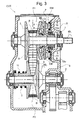
- figure 3 there is shown a practical construction of a continuously variable transmission CVT according to the diagram of figure 1.
- FIG. 3 namely the diagram according to figure 1
- the embodiment of figure 3 has the advantage of a great structural simplicity.
- the stator of the electric motor EM is fixed with respect to the bearing structure S, the supply of current to the stator winding 10a is particularly simple, no slip rings and associated brushes being necessary to that end.
- FIG 4 there is diagrammatically shown another embodiment of a continuously variable transmission CVT according to the invention.
- parts and components which have already been described have once again been indicated by using the same alphabetic/numerical symbols.
- a respective centrifugal mechanism for controlling the axial position of the slidable conical disc is associated with each of the pulleys P1 and P2 (the torque which can be transmitted is determined by the pushing force exerted by the spring coaxial with the secondary or output shaft). Furthermore, an electric motor similar to that already described in connection with pulley P1 is associated to the slidable conical disc 6 of the output pulley P2, for the electric correction of the speed of rotation of the spheres of the relevant centrifugal mechanism.
- the solution according to figure 4 allows a free control of the pressure force acting on the belt, which renders it possible to reduce the wastes caused by friction and improves the efficiency of the transmission.
- figure 5 there is shown a further variant of embodiment of the transmission according to figure 1.
- stator portion of the electric motor EM which is associated to the input pulley P1 is fixed
- stator portion is instead axially and rotationally solid with the input shaft 1.
- stator portion 10-10a of motor EM of figure 5 rotates thus at the same angular speed ⁇ 1 of the input shaft.
- the energisation of the electric motor EM allows then to modulate the relative angular speed ⁇ e of the rotor portion 7, 9 with respect to the speed ⁇ 1 of the input shaft.
- the control of the centrifugal forces acting on the spheres 8 of the mechanism CM can thus be performed with a lower consumption of electric energy, and moreover, the average speed of rotation of the spheres 8 is increased, and this makes possible to decrease their mass.
- FIG 6a to 6d there are shown four different operating situations corresponding to different values of the relative angular speed of ⁇ e of the rotor portion of the motor EM. It can be seen in particular that when ⁇ e is substantially equal to zero (figure 6b) the resultant tangential speed V of the spheres is now substantially equal to V 1 , i.e. it is doubled with respect to the corresponding condition of the CVT transmission of figure 1 (figure 2b).
- the variant of embodiment shown in figure 7 corresponds to that according to figure 5 as far as the control arrangement of the input pulley P1 is concerned, said arrangement comprising a centrifugal mechanism CM and an associated electric motor EM with a stator portion 10, 10a which rotates together with the input shaft 1.
- a similar arrangement is also associated with the output pulley P2.
- the control arrangement for that pulley comprises thus a centrifugal mechanism CM' with spheres 8' and a corresponding electric motor EM' having a stator portion 10', 10a', which is axially and angularly solid with the output shaft 2.
- the continuously variable transmissions according to the present invention are essentially characterised in that normally they operate like the simplest conventional transmissions having a centrifugal mechanism.
- a novel feature of the solutions according to the invention is the implementation of a relative simple electro-mechanical control system which allows to increase or decrease the angular speed of the masses (spheres) of the centrifugal mechanism(s) when a modification of the characteristics of operation of the transmission is needed.
- the electric motor or motors could be traditional "cylindrical" motors.
Landscapes
- Engineering & Computer Science (AREA)
- General Engineering & Computer Science (AREA)
- Mechanical Engineering (AREA)
- Transmissions By Endless Flexible Members (AREA)
- Control Of Transmission Device (AREA)
- Friction Gearing (AREA)
- Transmission Devices (AREA)
Abstract
Description
- The present invention relates to a continuously variable transmission system, particularly for motor-vehicles.
- More specifically, the invention concerns a continuously variable transmission system comprising an input shaft and an output shaft, essentially parallel with each other and provided with respective axially-expandable pulleys, coupled with one another by a belt; said pulleys comprising respective conical discs which rotate together with and which are slidable with respect to the respective shaft, and are disposed on opposite sides with respect to the belt; the movable conical disc coupled to the input shaft having an associated centrifugal mechanism for controlling the axial position thereof, said mechanism comprising a plurality of masses which are interposed between said conical disc and a contrast plate which is axially fixed with respect to the input shaft, said masses being radially displaceable under the effect of the centrifugal force.
- Continuously variable transmission systems of this kind are in use since many decades.
- Already in the Fifties of the past century such continuously variable transmission systems where used, for instance in the scooters of the model "Hobby" manufactured by DKW, in the motor-cycles of the model "Tina" manufactured by Triumph, and on the motor-cycles of the model "Ciao" manufactured by Piaggio. In said systems, which are structurally very simple, the displacement of the disc members of the input pulley was determined by a centrifugal mechanism, whereas the disc members of the output pulley where displaced towards each other by means of a spring. With said systems the obtainable transmission ratio and the capability of transferring torque were merely dependent on the speed of rotation of the input pulleys.
- Subsequently, more complex systems ,have been proposed ("Variomatic" system manufactured by Daf), in which the disc members of the output pulleys were moved one towards the other by means of a centrifugal mechanism and a pneumatic diaphragm actuator. In these kinds of systems the transmission ratios and the transferred torque could be controlled by acting onto two parameters, and this allowed to achieve better efficiencies.
- Later on transmissions have been proposed in which the input pulley was controlled by means of hydraulic thrust systems. Examples of such systems are disclosed for instance in SAE Technical Papers Nos. 930666-930668, and in ATZ, Automobil-Technische Zeitschrift 102 (2000), 7/8. The transmissions provided with such hydraulic thrust systems allow a high accuracy of control of the transmission ratio and of the compression force exerted on the trapezoid belt with respect to the transmitted torque. However, these transmissions have an excessive cost, due to the complicate structure and the need of using at least one pump and hydraulic actuators, as well as electrovalves and an associated electronic control system. The overall efficiency of such transmissions is furthermore decreased, due to the power needed for driving the hydraulic pump.
- Continuously variable transmissions having a mechanical-electronic control system of the transmission ratio are also known. An example of such a system is disclosed in JSAE Review 17 (1996). In that solution an electric motor is used, which through a three-stage gear reduction unit, a threaded coupling and a ball-baring, is capable of axially displacing a disc member of the input pulley, thus causing a variation of the transmission ratio. Such a system has the advantage of allowing the control to be performed electrically-electronically, and furthermore it has a lower consumption of energy with respect to the hydraulic solutions. However, said system is rather complicate and bulky.
- An aim of the present invention is to propose a continuously variable transmission (CVT) system of the initially defined kind, which allows to achieve an operation and performances similar to those of the best present solutions, however with a by far simplified structure and an extremely low manufacturing cost, and in which the variation of the transmission ratio is achieved with a minimum consumption of electric energy through the exploitation of the action of centrifugal masses.
- This and other aims are achieved according to the invention by a continuously variable transmission system of the aforesaid kind, characterised in that the said contrast plate is mounted rotatable about the input shaft, and electric motor means are associated to said plate so as to cause the relative rotation thereof at a variable speed with respect to the input shaft.
- Further characteristics and advantages of the invention will become apparent from the detailed description which follows, as a non-limiting example, with reference to the attached drawings, in which:
- figure 1 is a schematic diagram of a continuously variable transmission CVT according to the present invention;
- figure 2a to 2d are schematic diagrams which show different conditions of operation of a centrifugal mass of a centrifugal control mechanism comprised in the transmission according to figure 1;
- figure 3 is an axial cross-sectional view of an embodiment of a transmission in accordance with the diagram of figure 1;
- figure 4 is a schematic illustration of another continuously variable transmission according to the present invention;
- figure 5 is a schematic illustration of one further continuously variable transmission according to the present invention;
- figures 6a to 6d show different operating conditions of a sphere belonging to a centrifugal control mechanism comprised in the transmission according to figure 5; and
- figure 7 is a schematic illustration of another variant of a continuously variable transmission according to the present invention.
- In figure 1 a continuously variable transmission in accordance with the present invention is indicated as a whole as CVT.
- This transmission comprises an
input shaft 1 and anoutput shaft 2 on which respective axially expandable pulleys P1 and P2 are mounted so as to rotate together with said shafts, said pulleys being coupled with each other by a belt B having for instance a trapezoid cross-section. - In the illustrated embodiment the pulleys P1 and P2 comprise respective
conical discs shafts conical discs shafts - The axially slidable
conical discs conical discs - A centrifugal mechanism CM is associated to the slidable
conical disc 4 of pulley P1 to control the axial position thereof. In a per se known manner this mechanism comprises a plurality ofcentrifugal masses 8 which are interposed between saidconical disc 4 and acontrast plate 7 which is axially fixed with respect to theinput shaft 1 though being rotatable about the latter. - In a per se known manner, the
spheres 8 of the mechanism CM are capable, in the operation to be displaced radially towards the outside under the effect of the centrifugal force and to cause thus a displacement of the slidableconical disc 4 towards thedisc 3 which is fixed to theshaft 1, and a corresponding radial displacement toward the outside of the portion of the belt B which is engaged in the input pulley P1. As a consequence, a corresponding radial displacement toward the inside is caused onto the portion of the belt B which engages the output pulley P2, and a corresponding variation of the transmission ratio is determined between theinput shaft 1 and theoutput shaft 2. - In the transmission CVT according to the invention illustrated in figure 1 the
rotatable plate 7 represents part of the rotor of an electric control motor indicated as a whole by EM. To the surface of theplate 7 which faces away from pulley P1 there is fixed a distribution of permanent magnets 9 (rotor magnets), which facestator cores 10 provided with corresponding stator windings orcoils 10a. - A
spring 11 is coupled to theslidable disc 6 of the output pulley P2, and tends to push said conical disc towards theconical disc 5 which is fixed to theshaft 2, and through its pushing force establishes the torque which can be transmitted. - The
stator - The electric motor EM can be controlled in such a way as to cause, whenever necessary, a rotation of the
plate 7 with respect to theinput shaft 1, and this occurs at an angular speed and in the direction of rotation which are predetermined by an electronic control unit (not illustrated in the drawings), which is coupled to the transmission CVT. - In the drawings ω1 indicates the angular speed of the
input shaft 1 of the transmission, and ωe indicates the relative angular speed of therotor plate stator - In figures 2a to 2d V1 and Ve indicate the tangential speeds of diametrically opposed points of the surface of a
sphere 8 of the centrifugal mechanism CM, which speeds are due to the angular speed ω1 and ωe. Furthermore, V indicates the resulting tangential speed of the center of a givensphere 8. - Figures 2a-2d diagrammatically show the values of V1, Ve and V corresponding to four different values of the relative angular speed ωe of the rotor portion of motor EM with respect to the angular speed ω1 of the
input shaft 1. - In figure 2a there is shown the situation which occurs (in first approximation) when ωe is essentially equal to -ω1. In such a situation the tangential speeds of the points of contact of a given
sphere 8 with thedisc 4 and theplate 7 are essentially equal in magnitude and opposed in direction, and the tangential speed V of the center of the sphere is essentially equal to zero. - With reference to figure 2b, when the rotor portion of the electric motor EM is angularly at rest, namely when ωe is substantially equal to zero, the resulting tangential speed of the center of a given sphere is essentially equal to 0.5 V1.
- Figure 2c relates to the situation in which ωe is substantially equal in magnitude and in direction to the speed ω1 of the
input shaft 1. In that situation the resulting tangential speed V of the center of a givensphere 8 is essentially equal to V1. - Finally, referring to figure 2d, when ωe is equal to kω1, the speed V of the center of a
generic sphere 8 is essentially equal to 0.5 V1(k+1). - The examples of situations illustrated above with reference to figures 2a to 2d allow to appreciate that, for a given speed ω1 of the
input shaft 1, by varying the energisation of the stator of the electric motor EM it is possible to cause a variation of the resultant tangential speed of thespheres 8 of the centrifugal mechanism CM, and thus cause a corresponding variation of the distance between theconical discs - The transmission according to figure 1 is conveniently constructed such that the transmission ratio is normally determined only by the centrifugal mechanism CM and the simultaneous action of the
contrast spring 11, without the intervention of the electric motor EM. The latter is activated by an associated electronic control unit merely to "correct", when needed or convenient, the actual transmission ratio. - In the operation, when the electric motor EM is not activated, the
rotor plate 7 can be maintained essentially at rest (ωe=0) by the residual magnetism of thestator 10 so that in such a situation the angular speed of thespheres 8 of the centrifugal mechanism is essentially equal to 0.5 ω1. - In figure 3 there is shown a practical construction of a continuously variable transmission CVT according to the diagram of figure 1.
- The embodiment of figure 3 (namely the diagram according to figure 1) has the advantage of a great structural simplicity. Moreover, since the stator of the electric motor EM is fixed with respect to the bearing structure S, the supply of current to the stator winding 10a is particularly simple, no slip rings and associated brushes being necessary to that end.
- In figure 4 there is diagrammatically shown another embodiment of a continuously variable transmission CVT according to the invention. In that figure, parts and components which have already been described have once again been indicated by using the same alphabetic/numerical symbols.
- In the variant according to figure 4, a respective centrifugal mechanism for controlling the axial position of the slidable conical disc is associated with each of the pulleys P1 and P2 (the torque which can be transmitted is determined by the pushing force exerted by the spring coaxial with the secondary or output shaft). Furthermore, an electric motor similar to that already described in connection with pulley P1 is associated to the slidable
conical disc 6 of the output pulley P2, for the electric correction of the speed of rotation of the spheres of the relevant centrifugal mechanism. - In figure 4 the centrifugal mechanism and the electric motor which are associated to the output pulley P2, and the relevant components, have been indicated by using the same alphabetic/numeric symbols used in connection with the corresponding devices and components relevant to pulley P1, however with the addition of an apex.
- The solution according to figure 4 allows a free control of the pressure force acting on the belt, which renders it possible to reduce the wastes caused by friction and improves the efficiency of the transmission.
- In figure 5 there is shown a further variant of embodiment of the transmission according to figure 1.
- While in the transmission according to figure 1 the stator portion of the electric motor EM which is associated to the input pulley P1 is fixed, in the variant according to figure 5 the stator portion is instead axially and rotationally solid with the
input shaft 1. In the operation the stator portion 10-10a of motor EM of figure 5 rotates thus at the same angular speed ω1 of the input shaft. The energisation of the electric motor EM allows then to modulate the relative angular speed ωe of therotor portion spheres 8 of the mechanism CM can thus be performed with a lower consumption of electric energy, and moreover, the average speed of rotation of thespheres 8 is increased, and this makes possible to decrease their mass. - In figure 6a to 6d there are shown four different operating situations corresponding to different values of the relative angular speed of ωe of the rotor portion of the motor EM. It can be seen in particular that when ωe is substantially equal to zero (figure 6b) the resultant tangential speed V of the spheres is now substantially equal to V1, i.e. it is doubled with respect to the corresponding condition of the CVT transmission of figure 1 (figure 2b).
- In the variant according to figures 5 it is however necessary to use brushes and slip rings to allow the energisation of the windings of the
stator shaft 1, due to the fact that said shaft is now in one piece with the stator portion of the motor EM. - In figures 7 there is diagrammatically shown one further variant of embodiment. Also in said figure parts and components which have already been previously described have been attributed once again the same alphabetic/numeric references.
- In summary, the variant of embodiment shown in figure 7 corresponds to that according to figure 5 as far as the control arrangement of the input pulley P1 is concerned, said arrangement comprising a centrifugal mechanism CM and an associated electric motor EM with a
stator portion input shaft 1. In the variant according to figure 7 a similar arrangement is also associated with the output pulley P2. Besides the spring which determines the value of the torque which can be transmitted, the control arrangement for that pulley comprises thus a centrifugal mechanism CM' with spheres 8' and a corresponding electric motor EM' having astator portion 10', 10a', which is axially and angularly solid with theoutput shaft 2. - The way of operation of the continuously variable transmission according to figure 7 can be intuitively understood and therefore it will not be further described.
- As a whole, the continuously variable transmissions according to the present invention are essentially characterised in that normally they operate like the simplest conventional transmissions having a centrifugal mechanism. A novel feature of the solutions according to the invention is the implementation of a relative simple electro-mechanical control system which allows to increase or decrease the angular speed of the masses (spheres) of the centrifugal mechanism(s) when a modification of the characteristics of operation of the transmission is needed.
- Naturally, the principle of the invention remaining the same, the details of construction and the forms of embodiment may be varied widely with respect to those described and illustrated merely by way of example, without thereby departing from the scope of the present invention as defined in the annexed claims.
- In particular, in all the above disclosed arrangements the electric motor or motors could be traditional "cylindrical" motors.
Claims (7)
- A continuously variable transmission system (CVT), particularly for motor-vehicles, comprising an input shaft (1) and an output shaft (2) which are essentially parallel with each other and are provided with respective axially expandable pulleys (P1, P2) coupled with each other by a belt (B), said pulleys (P1, P2) comprising respective conical discs (4, 6) which are angularly solid with and axially slidable with respect to the corresponding shafts (1, 2) and are disposed on opposite sides with respect to the belt (B); the slidable conical disc (4) of the input shaft (1) having an associated centrifugal mechanism (CM; 8) for controlling the axial position of said conical disc (4), said mechanism comprising a plurality of centrifugal masses (8), particularly spheres, which are interposed between said conical disc (4) and a contrast plate (7) which is axially fixed with respect to the input shaft (1), and which are radially movable under the effect of the centrifugal force;
the system being characterised in that said contrast plate (7) is mounted rotatable about said input shaft (1) and in that to said plate (7) there are associated electric motor means (EM) capable of causing a relative rotation thereof at a variable speed with respect to the input shaft (1). - A continuously variable transmission system according to claim 1, wherein also to the slidable conical disc (6) of the pulley (P2) of the output shaft (2) there is associated a centrifugal mechanism (CM') for controlling the axial position of said conical disc (6), this mechanism comprising a plurality of masses (8'), which are interposed between said conical disc (6) and a further contrast plate (7') which is axially fixed with respect to the output shaft (2), and which are radially movable under the effect of the centrifugal force; to said further contrast plate (7'), which is rotatable about the output shaft (2), there being associated further electric motor means (EM') capable of causing a relative rotation thereof at a variable speed with respect to the output shaft (2).
- A continuously variable transmission system according to claim 1 or 2, wherein said electric motor means (EM; EM') comprise rotor permanent magnets (9; 9') fixed to the or each contrast plate (7; 7') and an axially fixed stator (10, 10a; 10', 10a').
- A continuously variable transmission system according to claim 3, wherein the or each stator (10, 10a; 10', 10a') is solid with a fixed support structure (S) in which the corresponding transmission shaft (1; 2) is mounted for rotation.
- A continuously variable transmission system according to any of claims 1 to 3, wherein the electric motor means (EM; EM') comprise a stator (10, 10a; 10', 10a') which is fixed for rotation with respect to the corresponding shaft of the transmission (1; 2).
- A continuously variable transmission system according to any of the preceding claims, wherein resilient means (11) are associated to the slidable conical disc (6) of the pulley (P2) of the output shaft (2), said resilient means (11) tending to push said slidable conical disc (6) toward the other conical disc (5) of the same pulley (P2).
- A continuously variable transmission system, particularly for motor-vehicles, substantially as described and illustrated, and for the purposed specified.
Priority Applications (4)
| Application Number | Priority Date | Filing Date | Title |
|---|---|---|---|
| DE602004009699T DE602004009699T2 (en) | 2004-11-25 | 2004-11-25 | Continuously variable transmission for motor vehicles |
| AT04425882T ATE376638T1 (en) | 2004-11-25 | 2004-11-25 | CONTINUOUSLY VARIABLE TRANSMISSION FOR MOTOR VEHICLES |
| PL04425882T PL1662182T3 (en) | 2004-11-25 | 2004-11-25 | Continuously variable transmission system, particularly for motor-vehicles |
| EP04425882A EP1662182B1 (en) | 2004-11-25 | 2004-11-25 | Continuously variable transmission system, particularly for motor-vehicles |
Applications Claiming Priority (1)
| Application Number | Priority Date | Filing Date | Title |
|---|---|---|---|
| EP04425882A EP1662182B1 (en) | 2004-11-25 | 2004-11-25 | Continuously variable transmission system, particularly for motor-vehicles |
Publications (2)
| Publication Number | Publication Date |
|---|---|
| EP1662182A1 true EP1662182A1 (en) | 2006-05-31 |
| EP1662182B1 EP1662182B1 (en) | 2007-10-24 |
Family
ID=34932911
Family Applications (1)
| Application Number | Title | Priority Date | Filing Date |
|---|---|---|---|
| EP04425882A Expired - Lifetime EP1662182B1 (en) | 2004-11-25 | 2004-11-25 | Continuously variable transmission system, particularly for motor-vehicles |
Country Status (4)
| Country | Link |
|---|---|
| EP (1) | EP1662182B1 (en) |
| AT (1) | ATE376638T1 (en) |
| DE (1) | DE602004009699T2 (en) |
| PL (1) | PL1662182T3 (en) |
Cited By (1)
| Publication number | Priority date | Publication date | Assignee | Title |
|---|---|---|---|---|
| WO2016139110A1 (en) * | 2015-03-05 | 2016-09-09 | Robert Bosch Gmbh | Cvt gearbox with improved controllability |
Families Citing this family (2)
| Publication number | Priority date | Publication date | Assignee | Title |
|---|---|---|---|---|
| DE102013210830A1 (en) | 2013-06-11 | 2014-12-11 | Schaeffler Technologies Gmbh & Co. Kg | powertrain |
| DE102015203902A1 (en) * | 2015-03-05 | 2016-09-08 | Robert Bosch Gmbh | CVT transmission with improved controllability and control method therefor |
Citations (3)
| Publication number | Priority date | Publication date | Assignee | Title |
|---|---|---|---|---|
| DE2715758A1 (en) * | 1976-04-09 | 1977-10-27 | Ferodo Sa | PULLEY FOR INVERTER CONVERTER |
| EP0558002A1 (en) * | 1992-02-26 | 1993-09-01 | Tochigifujisangyo Kabushiki Kaisha | Supercharging device for an internal combustion engine |
| WO2003048612A2 (en) * | 2001-12-04 | 2003-06-12 | Yamaha Hatsudoki Kabushiki Kaisha | Continuously variable transmission and method of controlling it |
-
2004
- 2004-11-25 EP EP04425882A patent/EP1662182B1/en not_active Expired - Lifetime
- 2004-11-25 PL PL04425882T patent/PL1662182T3/en unknown
- 2004-11-25 AT AT04425882T patent/ATE376638T1/en not_active IP Right Cessation
- 2004-11-25 DE DE602004009699T patent/DE602004009699T2/en not_active Expired - Lifetime
Patent Citations (3)
| Publication number | Priority date | Publication date | Assignee | Title |
|---|---|---|---|---|
| DE2715758A1 (en) * | 1976-04-09 | 1977-10-27 | Ferodo Sa | PULLEY FOR INVERTER CONVERTER |
| EP0558002A1 (en) * | 1992-02-26 | 1993-09-01 | Tochigifujisangyo Kabushiki Kaisha | Supercharging device for an internal combustion engine |
| WO2003048612A2 (en) * | 2001-12-04 | 2003-06-12 | Yamaha Hatsudoki Kabushiki Kaisha | Continuously variable transmission and method of controlling it |
Cited By (1)
| Publication number | Priority date | Publication date | Assignee | Title |
|---|---|---|---|---|
| WO2016139110A1 (en) * | 2015-03-05 | 2016-09-09 | Robert Bosch Gmbh | Cvt gearbox with improved controllability |
Also Published As
| Publication number | Publication date |
|---|---|
| DE602004009699D1 (en) | 2007-12-06 |
| EP1662182B1 (en) | 2007-10-24 |
| DE602004009699T2 (en) | 2008-03-06 |
| ATE376638T1 (en) | 2007-11-15 |
| PL1662182T3 (en) | 2008-01-31 |
Similar Documents
| Publication | Publication Date | Title |
|---|---|---|
| EP2325524B1 (en) | Stepless variable transmission device with parallel low gear wheel group | |
| US4163914A (en) | Infinitely variable ratio permanent magnet transmission | |
| EP2424081A1 (en) | Motor with transmission function | |
| EP4309988A1 (en) | Hub motor having integrated transmission mechanism | |
| US20120013211A1 (en) | Electric motor having a selectively adjustable base speed | |
| EP1662182B1 (en) | Continuously variable transmission system, particularly for motor-vehicles | |
| NL1019770C2 (en) | Electrically operated coupling with multiple start / generator means. | |
| KR101047224B1 (en) | Continuously variable transmission | |
| EP3392531B1 (en) | Automotive six-gear automatic transmission with brushless control-by-wire centrifugal ball arm jointing device | |
| CN201647067U (en) | Pawl variable speed power-driven hub | |
| EP3372868B1 (en) | Electric vehicle three-gear automatic transmission with brushless x-by-wire centrifugal ball arm engagement device | |
| JPS5865358A (en) | Transmission | |
| CN214690025U (en) | Hub motor integrated with speed change mechanism | |
| CN201824792U (en) | Sliding stopper electric variable speed hub | |
| EP1178242A2 (en) | Continuously-variable-ratio belt transmission assembly | |
| CN102673310A (en) | Variable speed electric hub with internal control pallet | |
| CN206850656U (en) | The special magnet ring type stepless speed change device of railway locomotive | |
| CN102407731A (en) | Automatic gear shifting hub for sliding gear | |
| JPH03163248A (en) | Belt type continuously variable transmission | |
| CN107289082B (en) | Conical ring type stepless gearbox | |
| KR0151384B1 (en) | Continuously variable transmission | |
| CN2833239Y (en) | Mechanical stepless automatic transmission | |
| RU2088033C1 (en) | Controlled electromagnetic clutch | |
| KR20250136163A (en) | Driving device for electric mobility and its control method | |
| KR20250111641A (en) | Driving device for electric mobility and its control method |
Legal Events
| Date | Code | Title | Description |
|---|---|---|---|
| PUAI | Public reference made under article 153(3) epc to a published international application that has entered the european phase |
Free format text: ORIGINAL CODE: 0009012 |
|
| AK | Designated contracting states |
Kind code of ref document: A1 Designated state(s): AT BE BG CH CY CZ DE DK EE ES FI FR GB GR HU IE IS IT LI LU MC NL PL PT RO SE SI SK TR |
|
| AX | Request for extension of the european patent |
Extension state: AL HR LT LV MK YU |
|
| 17P | Request for examination filed |
Effective date: 20060725 |
|
| AKX | Designation fees paid |
Designated state(s): AT BE BG CH CY CZ DE DK EE ES FI FR GB GR HU IE IS IT LI LU MC NL PL PT RO SE SI SK TR |
|
| GRAP | Despatch of communication of intention to grant a patent |
Free format text: ORIGINAL CODE: EPIDOSNIGR1 |
|
| GRAS | Grant fee paid |
Free format text: ORIGINAL CODE: EPIDOSNIGR3 |
|
| GRAA | (expected) grant |
Free format text: ORIGINAL CODE: 0009210 |
|
| AK | Designated contracting states |
Kind code of ref document: B1 Designated state(s): AT BE BG CH CY CZ DE DK EE ES FI FR GB GR HU IE IS IT LI LU MC NL PL PT RO SE SI SK TR |
|
| REG | Reference to a national code |
Ref country code: GB Ref legal event code: FG4D |
|
| REG | Reference to a national code |
Ref country code: CH Ref legal event code: EP |
|
| REG | Reference to a national code |
Ref country code: IE Ref legal event code: FG4D |
|
| REF | Corresponds to: |
Ref document number: 602004009699 Country of ref document: DE Date of ref document: 20071206 Kind code of ref document: P |
|
| REG | Reference to a national code |
Ref country code: PL Ref legal event code: T3 |
|
| NLV1 | Nl: lapsed or annulled due to failure to fulfill the requirements of art. 29p and 29m of the patents act | ||
| PG25 | Lapsed in a contracting state [announced via postgrant information from national office to epo] |
Ref country code: LI Free format text: LAPSE BECAUSE OF FAILURE TO SUBMIT A TRANSLATION OF THE DESCRIPTION OR TO PAY THE FEE WITHIN THE PRESCRIBED TIME-LIMIT Effective date: 20071024 Ref country code: NL Free format text: LAPSE BECAUSE OF FAILURE TO SUBMIT A TRANSLATION OF THE DESCRIPTION OR TO PAY THE FEE WITHIN THE PRESCRIBED TIME-LIMIT Effective date: 20071024 Ref country code: CH Free format text: LAPSE BECAUSE OF FAILURE TO SUBMIT A TRANSLATION OF THE DESCRIPTION OR TO PAY THE FEE WITHIN THE PRESCRIBED TIME-LIMIT Effective date: 20071024 Ref country code: ES Free format text: LAPSE BECAUSE OF FAILURE TO SUBMIT A TRANSLATION OF THE DESCRIPTION OR TO PAY THE FEE WITHIN THE PRESCRIBED TIME-LIMIT Effective date: 20080204 Ref country code: SE Free format text: LAPSE BECAUSE OF FAILURE TO SUBMIT A TRANSLATION OF THE DESCRIPTION OR TO PAY THE FEE WITHIN THE PRESCRIBED TIME-LIMIT Effective date: 20080124 |
|
| REG | Reference to a national code |
Ref country code: CH Ref legal event code: PL |
|
| ET | Fr: translation filed | ||
| PG25 | Lapsed in a contracting state [announced via postgrant information from national office to epo] |
Ref country code: SI Free format text: LAPSE BECAUSE OF FAILURE TO SUBMIT A TRANSLATION OF THE DESCRIPTION OR TO PAY THE FEE WITHIN THE PRESCRIBED TIME-LIMIT Effective date: 20071024 Ref country code: PT Free format text: LAPSE BECAUSE OF FAILURE TO SUBMIT A TRANSLATION OF THE DESCRIPTION OR TO PAY THE FEE WITHIN THE PRESCRIBED TIME-LIMIT Effective date: 20080324 Ref country code: BG Free format text: LAPSE BECAUSE OF FAILURE TO SUBMIT A TRANSLATION OF THE DESCRIPTION OR TO PAY THE FEE WITHIN THE PRESCRIBED TIME-LIMIT Effective date: 20080124 Ref country code: IS Free format text: LAPSE BECAUSE OF FAILURE TO SUBMIT A TRANSLATION OF THE DESCRIPTION OR TO PAY THE FEE WITHIN THE PRESCRIBED TIME-LIMIT Effective date: 20080224 |
|
| PG25 | Lapsed in a contracting state [announced via postgrant information from national office to epo] |
Ref country code: MC Free format text: LAPSE BECAUSE OF NON-PAYMENT OF DUE FEES Effective date: 20071130 Ref country code: AT Free format text: LAPSE BECAUSE OF FAILURE TO SUBMIT A TRANSLATION OF THE DESCRIPTION OR TO PAY THE FEE WITHIN THE PRESCRIBED TIME-LIMIT Effective date: 20071024 |
|
| PG25 | Lapsed in a contracting state [announced via postgrant information from national office to epo] |
Ref country code: CZ Free format text: LAPSE BECAUSE OF FAILURE TO SUBMIT A TRANSLATION OF THE DESCRIPTION OR TO PAY THE FEE WITHIN THE PRESCRIBED TIME-LIMIT Effective date: 20071024 Ref country code: DK Free format text: LAPSE BECAUSE OF FAILURE TO SUBMIT A TRANSLATION OF THE DESCRIPTION OR TO PAY THE FEE WITHIN THE PRESCRIBED TIME-LIMIT Effective date: 20071024 |
|
| PG25 | Lapsed in a contracting state [announced via postgrant information from national office to epo] |
Ref country code: SK Free format text: LAPSE BECAUSE OF FAILURE TO SUBMIT A TRANSLATION OF THE DESCRIPTION OR TO PAY THE FEE WITHIN THE PRESCRIBED TIME-LIMIT Effective date: 20071024 Ref country code: RO Free format text: LAPSE BECAUSE OF FAILURE TO SUBMIT A TRANSLATION OF THE DESCRIPTION OR TO PAY THE FEE WITHIN THE PRESCRIBED TIME-LIMIT Effective date: 20071024 Ref country code: BE Free format text: LAPSE BECAUSE OF FAILURE TO SUBMIT A TRANSLATION OF THE DESCRIPTION OR TO PAY THE FEE WITHIN THE PRESCRIBED TIME-LIMIT Effective date: 20071024 |
|
| PLBE | No opposition filed within time limit |
Free format text: ORIGINAL CODE: 0009261 |
|
| STAA | Information on the status of an ep patent application or granted ep patent |
Free format text: STATUS: NO OPPOSITION FILED WITHIN TIME LIMIT |
|
| 26N | No opposition filed |
Effective date: 20080725 |
|
| PG25 | Lapsed in a contracting state [announced via postgrant information from national office to epo] |
Ref country code: IE Free format text: LAPSE BECAUSE OF NON-PAYMENT OF DUE FEES Effective date: 20071126 |
|
| PG25 | Lapsed in a contracting state [announced via postgrant information from national office to epo] |
Ref country code: GR Free format text: LAPSE BECAUSE OF FAILURE TO SUBMIT A TRANSLATION OF THE DESCRIPTION OR TO PAY THE FEE WITHIN THE PRESCRIBED TIME-LIMIT Effective date: 20080125 Ref country code: EE Free format text: LAPSE BECAUSE OF FAILURE TO SUBMIT A TRANSLATION OF THE DESCRIPTION OR TO PAY THE FEE WITHIN THE PRESCRIBED TIME-LIMIT Effective date: 20071024 |
|
| PG25 | Lapsed in a contracting state [announced via postgrant information from national office to epo] |
Ref country code: FI Free format text: LAPSE BECAUSE OF FAILURE TO SUBMIT A TRANSLATION OF THE DESCRIPTION OR TO PAY THE FEE WITHIN THE PRESCRIBED TIME-LIMIT Effective date: 20071024 |
|
| GBPC | Gb: european patent ceased through non-payment of renewal fee |
Effective date: 20081125 |
|
| PG25 | Lapsed in a contracting state [announced via postgrant information from national office to epo] |
Ref country code: CY Free format text: LAPSE BECAUSE OF FAILURE TO SUBMIT A TRANSLATION OF THE DESCRIPTION OR TO PAY THE FEE WITHIN THE PRESCRIBED TIME-LIMIT Effective date: 20071024 |
|
| PG25 | Lapsed in a contracting state [announced via postgrant information from national office to epo] |
Ref country code: LU Free format text: LAPSE BECAUSE OF NON-PAYMENT OF DUE FEES Effective date: 20071125 |
|
| PG25 | Lapsed in a contracting state [announced via postgrant information from national office to epo] |
Ref country code: HU Free format text: LAPSE BECAUSE OF FAILURE TO SUBMIT A TRANSLATION OF THE DESCRIPTION OR TO PAY THE FEE WITHIN THE PRESCRIBED TIME-LIMIT Effective date: 20080425 Ref country code: TR Free format text: LAPSE BECAUSE OF FAILURE TO SUBMIT A TRANSLATION OF THE DESCRIPTION OR TO PAY THE FEE WITHIN THE PRESCRIBED TIME-LIMIT Effective date: 20071024 |
|
| PG25 | Lapsed in a contracting state [announced via postgrant information from national office to epo] |
Ref country code: GB Free format text: LAPSE BECAUSE OF NON-PAYMENT OF DUE FEES Effective date: 20081125 |
|
| PGFP | Annual fee paid to national office [announced via postgrant information from national office to epo] |
Ref country code: PL Payment date: 20150924 Year of fee payment: 12 |
|
| REG | Reference to a national code |
Ref country code: FR Ref legal event code: PLFP Year of fee payment: 12 |
|
| PGFP | Annual fee paid to national office [announced via postgrant information from national office to epo] |
Ref country code: IT Payment date: 20151109 Year of fee payment: 12 |
|
| PGFP | Annual fee paid to national office [announced via postgrant information from national office to epo] |
Ref country code: FR Payment date: 20151130 Year of fee payment: 12 |
|
| PGFP | Annual fee paid to national office [announced via postgrant information from national office to epo] |
Ref country code: DE Payment date: 20160129 Year of fee payment: 12 |
|
| REG | Reference to a national code |
Ref country code: DE Ref legal event code: R119 Ref document number: 602004009699 Country of ref document: DE |
|
| REG | Reference to a national code |
Ref country code: FR Ref legal event code: ST Effective date: 20170731 |
|
| PG25 | Lapsed in a contracting state [announced via postgrant information from national office to epo] |
Ref country code: FR Free format text: LAPSE BECAUSE OF NON-PAYMENT OF DUE FEES Effective date: 20161130 Ref country code: IT Free format text: LAPSE BECAUSE OF NON-PAYMENT OF DUE FEES Effective date: 20161125 |
|
| PG25 | Lapsed in a contracting state [announced via postgrant information from national office to epo] |
Ref country code: DE Free format text: LAPSE BECAUSE OF NON-PAYMENT OF DUE FEES Effective date: 20170601 |
|
| PG25 | Lapsed in a contracting state [announced via postgrant information from national office to epo] |
Ref country code: PL Free format text: LAPSE BECAUSE OF NON-PAYMENT OF DUE FEES Effective date: 20161125 |