EP1661838A1 - Discharge system for printed sheets - Google Patents
Discharge system for printed sheets Download PDFInfo
- Publication number
- EP1661838A1 EP1661838A1 EP05111020A EP05111020A EP1661838A1 EP 1661838 A1 EP1661838 A1 EP 1661838A1 EP 05111020 A EP05111020 A EP 05111020A EP 05111020 A EP05111020 A EP 05111020A EP 1661838 A1 EP1661838 A1 EP 1661838A1
- Authority
- EP
- European Patent Office
- Prior art keywords
- sheet
- discharge
- sheets
- wheel
- nip
- Prior art date
- Legal status (The legal status is an assumption and is not a legal conclusion. Google has not performed a legal analysis and makes no representation as to the accuracy of the status listed.)
- Granted
Links
- 238000007599 discharging Methods 0.000 claims abstract description 3
- 239000004677 Nylon Substances 0.000 claims description 3
- 229920001778 nylon Polymers 0.000 claims description 3
- 239000000835 fiber Substances 0.000 description 4
- 239000006260 foam Substances 0.000 description 4
- 230000001419 dependent effect Effects 0.000 description 1
- 230000000694 effects Effects 0.000 description 1
- 238000004519 manufacturing process Methods 0.000 description 1
- 238000000034 method Methods 0.000 description 1
- 239000004033 plastic Substances 0.000 description 1
Images
Classifications
-
- B—PERFORMING OPERATIONS; TRANSPORTING
- B65—CONVEYING; PACKING; STORING; HANDLING THIN OR FILAMENTARY MATERIAL
- B65H—HANDLING THIN OR FILAMENTARY MATERIAL, e.g. SHEETS, WEBS, CABLES
- B65H29/00—Delivering or advancing articles from machines; Advancing articles to or into piles
- B65H29/20—Delivering or advancing articles from machines; Advancing articles to or into piles by contact with rotating friction members, e.g. rollers, brushes, or cylinders
-
- B—PERFORMING OPERATIONS; TRANSPORTING
- B65—CONVEYING; PACKING; STORING; HANDLING THIN OR FILAMENTARY MATERIAL
- B65H—HANDLING THIN OR FILAMENTARY MATERIAL, e.g. SHEETS, WEBS, CABLES
- B65H29/00—Delivering or advancing articles from machines; Advancing articles to or into piles
- B65H29/12—Delivering or advancing articles from machines; Advancing articles to or into piles by means of the nip between two, or between two sets of, moving tapes or bands or rollers
- B65H29/14—Delivering or advancing articles from machines; Advancing articles to or into piles by means of the nip between two, or between two sets of, moving tapes or bands or rollers and introducing into a pile
-
- B—PERFORMING OPERATIONS; TRANSPORTING
- B65—CONVEYING; PACKING; STORING; HANDLING THIN OR FILAMENTARY MATERIAL
- B65H—HANDLING THIN OR FILAMENTARY MATERIAL, e.g. SHEETS, WEBS, CABLES
- B65H29/00—Delivering or advancing articles from machines; Advancing articles to or into piles
- B65H29/52—Stationary guides or smoothers
-
- B—PERFORMING OPERATIONS; TRANSPORTING
- B65—CONVEYING; PACKING; STORING; HANDLING THIN OR FILAMENTARY MATERIAL
- B65H—HANDLING THIN OR FILAMENTARY MATERIAL, e.g. SHEETS, WEBS, CABLES
- B65H2404/00—Parts for transporting or guiding the handled material
- B65H2404/50—Surface of the elements in contact with the forwarded or guided material
- B65H2404/56—Flexible surface
- B65H2404/561—Bristles, brushes
-
- B—PERFORMING OPERATIONS; TRANSPORTING
- B65—CONVEYING; PACKING; STORING; HANDLING THIN OR FILAMENTARY MATERIAL
- B65H—HANDLING THIN OR FILAMENTARY MATERIAL, e.g. SHEETS, WEBS, CABLES
- B65H2404/00—Parts for transporting or guiding the handled material
- B65H2404/60—Other elements in face contact with handled material
- B65H2404/61—Longitudinally-extending strips, tubes, plates, or wires
- B65H2404/612—Longitudinally-extending strips, tubes, plates, or wires and shaped for curvilinear transport path
-
- B—PERFORMING OPERATIONS; TRANSPORTING
- B65—CONVEYING; PACKING; STORING; HANDLING THIN OR FILAMENTARY MATERIAL
- B65H—HANDLING THIN OR FILAMENTARY MATERIAL, e.g. SHEETS, WEBS, CABLES
- B65H2801/00—Application field
- B65H2801/03—Image reproduction devices
- B65H2801/06—Office-type machines, e.g. photocopiers
Definitions
- the invention relates to a discharge system for printed media sheets, comprising: a tray for the media sheets; rotating transport elements forming a discharge nip for discharging the sheets onto the tray; a guide plate having a surface for guiding the sheets to the discharge nip; and a rotating wheel comprising bristles for guiding the sheets towards the discharge nip.
- the media sheets are frequently collected on one or more trays.
- the media sheets may be supplied, for example, from a stack of cut sheets, or may be continuously supplied from a reel and then cut into sheets.
- the media sheets are supplied from a reel, they are often slightly curled. This effect becomes even more pronounced when the end of the coil on the reel is reached and the radius of curvature of the reel becomes smaller. But also when the media sheets are supplied from a stack of cut sheets, they may become curled during the printing process, for example.
- the configuration of the discharge system may require a certain length of the guide plate.
- the tray may be positioned above the printing unit, and a curved guide plate is needed to reverse the sheet transport direction before the sheet is discharged onto the tray.
- JP 08002775 A shows a paper discharge device in which a brush roller is arranged in the way of the leading edge of a sheet.
- the brush roller guides the sheet to a paper through direction or to a paper discharge direction.
- the sheet is guided between the brush roller and a guiding surface which is curved away from the brush roller, and is then funneled through a space between said guiding surface and an opposing guiding surface towards the discharge rollers.
- a curled sheet might curl around the brush roller instead of being funneled towards the discharge rollers.
- the paper discharge device is suitable only for dry sheets, because the sheet is conveyed between pairs of conveying rollers towards the brush roller, and because any surface of the sheet may be guided to a side of the brush roller where it gets into a sliding contact with an opposing wall.
- EP 0 407 152 A2 shows a sheet stacker in which fiber brushes and foam drive rolls are arranged on a rotatable drive shaft.
- the diameter of the fiber brushes is greater than that of the foam drive rolls, so that the fiber brushes urge a leading edge of a sheet being fed vertically downward toward a nip being formed between the foam drive rolls and a baffle which is bent away from the foam drive rolls.
- both sides of the sheet will be in sliding contact with walls that guide the sheet towards the fiber brushes, so that the sheet stacker can only be used for dry sheets.
- US 4 824 091 A shows a sheet collection device in which a sheet is guided between opposing straight walls to a discharge opening, while the sheet is engaged between two nip rollers.
- Rotatable brushes are arranged at the discharge opening to wipe down against a trail end of a sheet that has been discharged onto a tray.
- the brushes are arrange coaxially with one of the nip rollers and force a leading edge of a sheet against the opposing wall and into engagement with the nip rollers.
- the brushes do not assist in threading the sheet into the entrance slit between the opposing walls, so that a curled sheet might get folded there.
- this object is achieved by a discharge system of the type indicated above, wherein at least one driven transport belt forms one of the transport elements defining the discharge nip; the guide plate passing in approximately a half turn around two pulleys around which the transport belt is passed; the wheel facing the surface of the guide plate; the transport belt being arranged to guide the sheets towards the discharge nip and the wheel being arranged to guide the sheets to the transport belt.
- the wheel may also be configured as a drum extending essentially over the whole width of the guide plate.
- the wheel When a sheet is guided along the guide plate, the wheel is situated on a first side of the sheet, where the image has been printed, and the guide plate is situated on the other side of the sheet. There may be free space between the wheel and the guide plate, so that a sheet that is only moderately curled may be guided by the guide plate without contacting the wheel. However, a sheet that is strongly curled will be confined in the space between the wheel and the guide plate.
- the bristles only touch the sheet at small points, so that the printed image on the sheet is not damaged in case the ink has not dried.
- the bristles are radial bristles.
- the wheel is laterally offset from one of the transport elements defining the discharge nip and partially intersects the cross-section of said transport element.
- an edge or an area of the sheet that is in contact with and guided by the wheel will be handed over to the transport elements.
- the guide plate is curved and passes in approximately a half turn around the wheel. Thereby, the guide plane turns over the sheet and reverses the transport direction of the sheet. In this case, guidance of the sheet is specifically needed to avoid that the sheet gets folded and the transport elements are jammed.
- the bristles are arranged in bunches distributed over the circumference of the wheel; the bunches being staggered in at least two rows.
- a wheel with bunches is easier to manufacture than a wheel with evenly distributed singulated bristles.
- the bristles are uniformly distributed over the circumference of the wheel.
- the bristles are made of plastic, in particular nylon. It has been found that nylon bristles are especially advantageous in that damage a printed image is avoided even when the ink has not dried completely.
- the wheel is arranged coaxially to one of the pulleys; the bristles extending further than the diameter of said pulley.
- the curled part of the sheet that is being moved towards said pulley is prevented from hitting the transport belt where it is curved around the pulley.
- the curled part of the sheet is guided by the bristles to a straight part of the transport belt. Thereby, a damaging of a printed surface of the sheet is avoided.
- an ink jet printer comprises a platen 10 which is intermittently driven to rotate in order to advance a sheet 12, e. g. a sheet of paper, in a direction indicated by an arrow A over the top surface of a sheet support plate 14.
- a number of transport rollers 16 are rotatably supported in a cover plate 18 and form a transport nip with the platen 10 so that the sheet 12, which is supplied from a reel 19 via a guide plate 20, is paid out through a gap formed between an edge of the cover plate 18 and the surface of the sheet support plate 14.
- a carriage 22 which includes a number of ink jet print heads (not shown) is mounted above the sheet support plate 14 so as to reciprocate in a direction that is perpendicular to the plane of the drawing across the sheet 12.
- a number of pixel lines are printed on the sheet 12 by means of the print heads which eject droplets of ink onto the sheet in accordance with image information supplied to the print heads.
- guide and drive means for the carriage 22, ink supply lines and data supply lines for the print heads, and the like, have not been shown in the drawing.
- the top surface of the sheet support plate 14 has a regular pattern of suction holes (not shown) through which the sheet 12 is sucked against the flat surface of the support plate 14 and is thereby held in a flat condition, especially in the area which is scanned by the carriage 22, so that a uniform distance between the nozzles of the printheads and the surface of the sheet 12 is established over the whole width of the sheet and a high print quality can be achieved.
- the sheet 12 is further advanced along a surface 111 of a curved guide plate 112 that turns the sheet upside down and reverses the transport direction of the sheet 12.
- the sheet 12 is then fed to a discharge nip 114 formed between a plurality of discharge rollers 116 and a plurality of rubber-coated transport belts 118 which are each passed around a pair of pulleys 120 and 122 (pulley 122 being not visible in Fig. 2).
- the direction of movement of the transport belts 118 is indicated by arrows.
- the discharge rollers 116 are mounted on a common axle 116a, and the pulleys 120 and 122 are also mounted on common axles 120a and 122a, respectively.
- the sheet 12 is discharged onto a tray 124.
- the tray 124 has a top surface 126 for supporting the sheets and has stops 132 at which the trailing edges of the sheets 12 will be aligned.
- a discharge sensor 136 is arranged near the discharge nip 114 to indicate when the trailing edge of the sheet 12 has been discharged from the discharge nip 114.
- the discharge sensor 136 is of conventional design and comprises an arm that is pivotable about an axis.
- a top frame member 138 of the tray 124 carries a tray-full sensor 140 which is also of conventional design comprising an arm that is pivotably mounted on the frame member 138.
- the hump 170 is guided by a wheel 172 comprising radial bunches of bristles 174.
- the bunches are alternately arranged in two circumferential rows 176, 178 which are laterally offset from one another.
- the bunches of a first row 176 of bunches are hatched and lie within the plane of the drawing.
- the bunches of a second row 178 of bunches are plainly drawn and lie behind the plane of the drawing.
- the wheel 172 is arranged on the axle 122a and rotates together with the pulley 122 in a direction that is indicated by an arrow in Fig. 2.
- the bristles 174 contact the hump 170 of the sheet 12s and thereby guide the sheet 12s without damaging the printed surface of the sheet 12s. Thus, it is avoided that the leading edge of the sheet 12s is folded back, as it might be the case if the wheel 172 and the pulley 122 were not present.
- the discharge system of Fig. 2 may also be used with a sheet that is curled even stronger.
- a sheet 12t is also indicated in Fig. 2.
- the leading edge of the sheet 12t comes into contact with the wheel 172 and is guided in the direction that is indicated by an arrow.
- the wheel 172 will get into contact with the printed surface of the sheet 12t. Again, a damaging of the printed surface is avoided.
Landscapes
- Engineering & Computer Science (AREA)
- Mechanical Engineering (AREA)
- Separation, Sorting, Adjustment, Or Bending Of Sheets To Be Conveyed (AREA)
- Feeding Of Articles By Means Other Than Belts Or Rollers (AREA)
- Handling Of Cut Paper (AREA)
- Delivering By Means Of Belts And Rollers (AREA)
- Pile Receivers (AREA)
- Discharge By Other Means (AREA)
- Laminated Bodies (AREA)
- Diaphragms For Electromechanical Transducers (AREA)
- Basic Packing Technique (AREA)
Abstract
Description
- The invention relates to a discharge system for printed media sheets, comprising: a tray for the media sheets; rotating transport elements forming a discharge nip for discharging the sheets onto the tray; a guide plate having a surface for guiding the sheets to the discharge nip; and a rotating wheel comprising bristles for guiding the sheets towards the discharge nip.
- In printers and copiers, printed media sheets are frequently collected on one or more trays. The media sheets may be supplied, for example, from a stack of cut sheets, or may be continuously supplied from a reel and then cut into sheets. When the media sheets are supplied from a reel, they are often slightly curled. This effect becomes even more pronounced when the end of the coil on the reel is reached and the radius of curvature of the reel becomes smaller. But also when the media sheets are supplied from a stack of cut sheets, they may become curled during the printing process, for example.
- When the sheets are guided along the surface of the guide plate towards the discharge nip, in case of a curled sheet, a part of the sheet may stick out from the guide plate. This might prevent the leading edge of the sheet from being properly threaded to the discharge nip, possibly resulting in the sheet getting folded. This danger cannot be avoided by an arrangement ensuring that the transport elements immediately engage a sheet when it is fed to the discharge system, for the following reasons. In case the sheet has been printed with ink, the ink might not be completely dry when the sheet is fed to the discharge system, so that the printed image might get blurred. Moreover, the configuration of the discharge system may require a certain length of the guide plate. For example, in a printer the tray may be positioned above the printing unit, and a curved guide plate is needed to reverse the sheet transport direction before the sheet is discharged onto the tray.
- JP 08002775 A shows a paper discharge device in which a brush roller is arranged in the way of the leading edge of a sheet. Depending on the rotation direction of the brush roller, the brush roller guides the sheet to a paper through direction or to a paper discharge direction. In the latter case, the sheet is guided between the brush roller and a guiding surface which is curved away from the brush roller, and is then funneled through a space between said guiding surface and an opposing guiding surface towards the discharge rollers. However, a curled sheet might curl around the brush roller instead of being funneled towards the discharge rollers. Moreover, the paper discharge device is suitable only for dry sheets, because the sheet is conveyed between pairs of conveying rollers towards the brush roller, and because any surface of the sheet may be guided to a side of the brush roller where it gets into a sliding contact with an opposing wall.
- From EP 0 407 151 A2, a similar sheet path selector with a bidirectionally rotatable brush wheel is known.
- EP 0 407 152 A2 shows a sheet stacker in which fiber brushes and foam drive rolls are arranged on a rotatable drive shaft. The diameter of the fiber brushes is greater than that of the foam drive rolls, so that the fiber brushes urge a leading edge of a sheet being fed vertically downward toward a nip being formed between the foam drive rolls and a baffle which is bent away from the foam drive rolls. However, both sides of the sheet will be in sliding contact with walls that guide the sheet towards the fiber brushes, so that the sheet stacker can only be used for dry sheets.
- US 4 824 091 A shows a sheet collection device in which a sheet is guided between opposing straight walls to a discharge opening, while the sheet is engaged between two nip rollers. Rotatable brushes are arranged at the discharge opening to wipe down against a trail end of a sheet that has been discharged onto a tray. The brushes are arrange coaxially with one of the nip rollers and force a leading edge of a sheet against the opposing wall and into engagement with the nip rollers. However, the brushes do not assist in threading the sheet into the entrance slit between the opposing walls, so that a curled sheet might get folded there.
- It is an object of the invention to provide a discharge system that ensures that curled media sheets are properly fed to the discharge nip. It is also an object of the invention to provide a printer comprising such discharge system.
- According to the invention, this object is achieved by a discharge system of the type indicated above, wherein at least one driven transport belt forms one of the transport elements defining the discharge nip; the guide plate passing in approximately a half turn around two pulleys around which the transport belt is passed; the wheel facing the surface of the guide plate; the transport belt being arranged to guide the sheets towards the discharge nip and the wheel being arranged to guide the sheets to the transport belt. The wheel may also be configured as a drum extending essentially over the whole width of the guide plate.
- When a sheet is guided along the guide plate, the wheel is situated on a first side of the sheet, where the image has been printed, and the guide plate is situated on the other side of the sheet. There may be free space between the wheel and the guide plate, so that a sheet that is only moderately curled may be guided by the guide plate without contacting the wheel. However, a sheet that is strongly curled will be confined in the space between the wheel and the guide plate. The bristles only touch the sheet at small points, so that the printed image on the sheet is not damaged in case the ink has not dried. Preferably, the bristles are radial bristles.
- Useful details of the invention are indicated in the dependent claims.
- Preferably, the wheel is laterally offset from one of the transport elements defining the discharge nip and partially intersects the cross-section of said transport element. Thereby, an edge or an area of the sheet that is in contact with and guided by the wheel will be handed over to the transport elements.
- In one embodiment, the guide plate is curved and passes in approximately a half turn around the wheel. Thereby, the guide plane turns over the sheet and reverses the transport direction of the sheet. In this case, guidance of the sheet is specifically needed to avoid that the sheet gets folded and the transport elements are jammed.
- Preferably, the bristles are arranged in bunches distributed over the circumference of the wheel; the bunches being staggered in at least two rows. A wheel with bunches is easier to manufacture than a wheel with evenly distributed singulated bristles. Further, due to the staggering of the bunches, the bristles are uniformly distributed over the circumference of the wheel.
- Preferably, the bristles are made of plastic, in particular nylon. It has been found that nylon bristles are especially advantageous in that damage a printed image is avoided even when the ink has not dried completely.
- Preferably, the wheel is arranged coaxially to one of the pulleys; the bristles extending further than the diameter of said pulley. Thereby, a curled part of the sheet that is being moved towards said pulley is prevented from hitting the transport belt where it is curved around the pulley. Instead, the curled part of the sheet is guided by the bristles to a straight part of the transport belt. Thereby, a damaging of a printed surface of the sheet is avoided.
- A preferred embodiment of the invention will now be described in conjunction with the drawings in which:
- Fig. 1
- is a schematic partial cross-sectional view of a printer; and
- Fig. 2
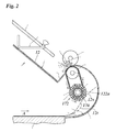
- shows details of a sheet discharge system of the printer shown in Fig. 1.
- As is shown in Fig. 1, an ink jet printer comprises a
platen 10 which is intermittently driven to rotate in order to advance asheet 12, e. g. a sheet of paper, in a direction indicated by an arrow A over the top surface of a sheet support plate 14. A number of transport rollers 16 are rotatably supported in a cover plate 18 and form a transport nip with theplaten 10 so that thesheet 12, which is supplied from a reel 19 via a guide plate 20, is paid out through a gap formed between an edge of the cover plate 18 and the surface of the sheet support plate 14. - A carriage 22 which includes a number of ink jet print heads (not shown) is mounted above the sheet support plate 14 so as to reciprocate in a direction that is perpendicular to the plane of the drawing across the
sheet 12. In each pass of the carriage 22, a number of pixel lines are printed on thesheet 12 by means of the print heads which eject droplets of ink onto the sheet in accordance with image information supplied to the print heads. For the sake of simplicity, guide and drive means for the carriage 22, ink supply lines and data supply lines for the print heads, and the like, have not been shown in the drawing. - The top surface of the sheet support plate 14 has a regular pattern of suction holes (not shown) through which the
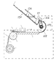
sheet 12 is sucked against the flat surface of the support plate 14 and is thereby held in a flat condition, especially in the area which is scanned by the carriage 22, so that a uniform distance between the nozzles of the printheads and the surface of thesheet 12 is established over the whole width of the sheet and a high print quality can be achieved. Thesheet 12 is further advanced along a surface 111 of acurved guide plate 112 that turns the sheet upside down and reverses the transport direction of thesheet 12. - As is shown in Fig. 1 and, in more detailed view, in Fig. 2, the
sheet 12 is then fed to a discharge nip 114 formed between a plurality ofdischarge rollers 116 and a plurality of rubber-coated transport belts 118 which are each passed around a pair of pulleys 120 and 122 (pulley 122 being not visible in Fig. 2). The direction of movement of the transport belts 118 is indicated by arrows. Thedischarge rollers 116 are mounted on a common axle 116a, and the pulleys 120 and 122 are also mounted oncommon axles 120a and 122a, respectively. From the discharge nip 114, thesheet 12 is discharged onto atray 124. Thetray 124 has atop surface 126 for supporting the sheets and has stops 132 at which the trailing edges of thesheets 12 will be aligned. - A discharge sensor 136 is arranged near the discharge nip 114 to indicate when the trailing edge of the
sheet 12 has been discharged from the discharge nip 114. The discharge sensor 136 is of conventional design and comprises an arm that is pivotable about an axis. - A top frame member 138 of the
tray 124 carries a tray-full sensor 140 which is also of conventional design comprising an arm that is pivotably mounted on the frame member 138. - So far, the transport of the
sheet 12 along the surface 111 of theguide plate 112 has been described. However, when the sheet is supplied from the reel 19 (Fig. 1), it may curl after it has left the sheet support plate 14. A curledsheet 12s is indicated in a chaindotted line in Fig. 2. Thesheet 12s forms ahump 170 that sticks out from theguide plate 112. - The
hump 170 is guided by awheel 172 comprising radial bunches of bristles 174. The bunches are alternately arranged in two circumferential rows 176, 178 which are laterally offset from one another. In Fig. 2, the bunches of a first row 176 of bunches are hatched and lie within the plane of the drawing. The bunches of a second row 178 of bunches are plainly drawn and lie behind the plane of the drawing. - The
wheel 172 is arranged on theaxle 122a and rotates together with the pulley 122 in a direction that is indicated by an arrow in Fig. 2. The bristles 174 contact thehump 170 of thesheet 12s and thereby guide thesheet 12s without damaging the printed surface of thesheet 12s. Thus, it is avoided that the leading edge of thesheet 12s is folded back, as it might be the case if thewheel 172 and the pulley 122 were not present. - The discharge system of Fig. 2 may also be used with a sheet that is curled even stronger. Such a
sheet 12t is also indicated in Fig. 2. In this case, the leading edge of thesheet 12t comes into contact with thewheel 172 and is guided in the direction that is indicated by an arrow. When the leading edge of thesheet 12t is transported along thewheel 172, thewheel 172 will get into contact with the printed surface of thesheet 12t. Again, a damaging of the printed surface is avoided.
Claims (6)
Priority Applications (1)
| Application Number | Priority Date | Filing Date | Title |
|---|---|---|---|
| EP05111020A EP1661838B1 (en) | 2004-11-25 | 2005-11-21 | Discharge system for printed sheets |
Applications Claiming Priority (2)
| Application Number | Priority Date | Filing Date | Title |
|---|---|---|---|
| EP04106080 | 2004-11-25 | ||
| EP05111020A EP1661838B1 (en) | 2004-11-25 | 2005-11-21 | Discharge system for printed sheets |
Publications (2)
| Publication Number | Publication Date |
|---|---|
| EP1661838A1 true EP1661838A1 (en) | 2006-05-31 |
| EP1661838B1 EP1661838B1 (en) | 2008-04-30 |
Family
ID=34929942
Family Applications (1)
| Application Number | Title | Priority Date | Filing Date |
|---|---|---|---|
| EP05111020A Expired - Lifetime EP1661838B1 (en) | 2004-11-25 | 2005-11-21 | Discharge system for printed sheets |
Country Status (6)
| Country | Link |
|---|---|
| US (1) | US7407160B2 (en) |
| EP (1) | EP1661838B1 (en) |
| JP (1) | JP4708166B2 (en) |
| CN (1) | CN1778657A (en) |
| AT (1) | ATE393749T1 (en) |
| DE (1) | DE602005006361T2 (en) |
Families Citing this family (11)
| Publication number | Priority date | Publication date | Assignee | Title |
|---|---|---|---|---|
| JP5112626B2 (en) * | 2004-11-25 | 2013-01-09 | オセ−テクノロジーズ・ベー・ヴエー | Sheet discharge system |
| US20070052164A1 (en) * | 2005-09-05 | 2007-03-08 | Hiroyuki Watase | Sheet-feeding auxiliary device, image forming device, and image reading device |
| JP4523572B2 (en) * | 2006-07-10 | 2010-08-11 | シャープ株式会社 | Output stacker |
| JP4621219B2 (en) * | 2007-02-26 | 2011-01-26 | 株式会社リコー | Sheet conveying apparatus and image forming apparatus |
| JP5339931B2 (en) * | 2008-01-30 | 2013-11-13 | キヤノン株式会社 | Sheet discharging apparatus and image forming apparatus |
| JP2009203067A (en) * | 2008-02-29 | 2009-09-10 | Canon Inc | Sheet carrying device, control method for sheet carrying device, storage medium, and program |
| JP5390164B2 (en) * | 2008-10-17 | 2014-01-15 | 富士通フロンテック株式会社 | Paper sheet discharge and accumulation device |
| JP6164401B2 (en) * | 2013-02-28 | 2017-07-19 | 株式会社リコー | Paper discharge device and image forming apparatus having the same |
| JP2014213978A (en) * | 2013-04-23 | 2014-11-17 | キヤノン株式会社 | Sheet loading device, and image formation device |
| CN107572276A (en) * | 2017-09-01 | 2018-01-12 | 苏州欣航微电子有限公司 | A kind of neat device of transfer air blowing for paper guide |
| USD914317S1 (en) | 2019-02-13 | 2021-03-23 | Retail Design Services, LLC | Shopping cart |
Citations (7)
| Publication number | Priority date | Publication date | Assignee | Title |
|---|---|---|---|---|
| US3948505A (en) * | 1974-11-01 | 1976-04-06 | Control Data Corporation | Document turn-around sorter/stacker |
| US4824091A (en) | 1982-07-07 | 1989-04-25 | Xerox Corporation | Sheet collection devices and sheet processors utilizing same |
| EP0407151A2 (en) | 1989-07-03 | 1991-01-09 | Xerox Corporation | Rotating brush decision gate |
| EP0407152A2 (en) | 1989-07-03 | 1991-01-09 | Xerox Corporation | Sheet stackers |
| JPH082775A (en) | 1994-06-14 | 1996-01-09 | Ricoh Co Ltd | Paper ejection device |
| US5709376A (en) * | 1995-01-30 | 1998-01-20 | Ricoh Company, Ltd. | Sheet finisher |
| US20040113359A1 (en) * | 2001-06-14 | 2004-06-17 | Ure Hostettler | Sheet diverting assembly |
Family Cites Families (18)
| Publication number | Priority date | Publication date | Assignee | Title |
|---|---|---|---|---|
| US3840224A (en) * | 1973-04-11 | 1974-10-08 | Addressograph Multigraph | Sheet feeding apparatus for copying machines |
| JPS5438043A (en) * | 1977-08-31 | 1979-03-22 | Tsunoda Jitensha Kk | Drive device of electric bicycle |
| JPS59177227A (en) * | 1983-03-24 | 1984-10-06 | Nec Corp | Paper-sheet feeding apparatus |
| GB8315734D0 (en) * | 1983-06-08 | 1983-07-13 | Xerox Corp | Sheet reversing apparatus |
| US5215300A (en) * | 1985-03-15 | 1993-06-01 | Canon Kabushiki Kaisha | Tray apparatus |
| JPH0694325B2 (en) * | 1985-09-18 | 1994-11-24 | 株式会社日立製作所 | Paper processing equipment |
| JP2862234B2 (en) * | 1986-06-03 | 1999-03-03 | キヤノン株式会社 | Sheet discharge loading device |
| US4884798A (en) * | 1988-03-11 | 1989-12-05 | Imagitek | Copy turn around mechanism for reproduction machine |
| JP2624530B2 (en) * | 1988-11-08 | 1997-06-25 | 日本金銭機械株式会社 | Paper transport device |
| JPH04243762A (en) * | 1991-01-28 | 1992-08-31 | Fuji Xerox Co Ltd | Paper reversing device |
| CA2096392C (en) * | 1992-05-18 | 1999-12-28 | Lawrence D. Miles | Printer support mechanism and method |
| JP2595418B2 (en) * | 1992-07-14 | 1997-04-02 | 株式会社リコー | Image forming device |
| BR9800333A (en) * | 1997-01-21 | 1999-06-29 | Xerox Corp | Removable postal sheet de-curler module and high-capacity stacker removable external module that is adapted to rest on a sheet receiving tray of a printing machine to uncap and capture cut sheets and printing machine |
| US6145833A (en) * | 1998-06-02 | 2000-11-14 | Marquip, Inc. | Rotary brush sheet deceleration device |
| JP3526226B2 (en) * | 1998-11-11 | 2004-05-10 | キヤノン株式会社 | Sheet processing apparatus and image forming apparatus having the same |
| JP3010557B1 (en) * | 1999-04-09 | 2000-02-21 | 株式会社東京機械製作所 | Impeller device for discharge of folder |
| US6623003B1 (en) * | 1999-09-17 | 2003-09-23 | Fuji Photo Film Co., Ltd. | Sheet material stacking device and automatic exposure device for a printing plate |
| JP4015582B2 (en) * | 2003-05-09 | 2007-11-28 | ニスカ株式会社 | Image forming apparatus |
-
2005
- 2005-11-17 JP JP2005332411A patent/JP4708166B2/en not_active Expired - Fee Related
- 2005-11-21 AT AT05111020T patent/ATE393749T1/en not_active IP Right Cessation
- 2005-11-21 EP EP05111020A patent/EP1661838B1/en not_active Expired - Lifetime
- 2005-11-21 DE DE602005006361T patent/DE602005006361T2/en not_active Expired - Lifetime
- 2005-11-23 US US11/285,349 patent/US7407160B2/en not_active Expired - Fee Related
- 2005-11-25 CN CNA2005101255649A patent/CN1778657A/en active Pending
Patent Citations (7)
| Publication number | Priority date | Publication date | Assignee | Title |
|---|---|---|---|---|
| US3948505A (en) * | 1974-11-01 | 1976-04-06 | Control Data Corporation | Document turn-around sorter/stacker |
| US4824091A (en) | 1982-07-07 | 1989-04-25 | Xerox Corporation | Sheet collection devices and sheet processors utilizing same |
| EP0407151A2 (en) | 1989-07-03 | 1991-01-09 | Xerox Corporation | Rotating brush decision gate |
| EP0407152A2 (en) | 1989-07-03 | 1991-01-09 | Xerox Corporation | Sheet stackers |
| JPH082775A (en) | 1994-06-14 | 1996-01-09 | Ricoh Co Ltd | Paper ejection device |
| US5709376A (en) * | 1995-01-30 | 1998-01-20 | Ricoh Company, Ltd. | Sheet finisher |
| US20040113359A1 (en) * | 2001-06-14 | 2004-06-17 | Ure Hostettler | Sheet diverting assembly |
Non-Patent Citations (1)
| Title |
|---|
| PATENT ABSTRACTS OF JAPAN vol. 1996, no. 05 31 May 1996 (1996-05-31) * |
Also Published As
| Publication number | Publication date |
|---|---|
| CN1778657A (en) | 2006-05-31 |
| JP4708166B2 (en) | 2011-06-22 |
| US20060181019A1 (en) | 2006-08-17 |
| JP2006151695A (en) | 2006-06-15 |
| DE602005006361D1 (en) | 2008-06-12 |
| ATE393749T1 (en) | 2008-05-15 |
| US7407160B2 (en) | 2008-08-05 |
| DE602005006361T2 (en) | 2009-06-10 |
| EP1661838B1 (en) | 2008-04-30 |
Similar Documents
| Publication | Publication Date | Title |
|---|---|---|
| JP3469824B2 (en) | Recording medium transport device | |
| US5163674A (en) | Drive means for a recording medium having liquid images thereon | |
| US20090190982A1 (en) | Printing system | |
| JPH07112841A (en) | Sheet conveying apparatus and image forming apparatus | |
| EP1661838B1 (en) | Discharge system for printed sheets | |
| JP7439528B2 (en) | Paper feeding device and image forming device | |
| JP2003095501A (en) | Sheet material transport device and image forming device | |
| CN102085750A (en) | Image forming device | |
| JP5112626B2 (en) | Sheet discharge system | |
| JP5932737B2 (en) | Inkjet recording device | |
| JP2012193042A (en) | Image forming device and delivered paper sheet stacking device | |
| US8326205B2 (en) | Medium cutting device, image recording apparatus having the medium cutting device, and controlling method of the medium cutting device | |
| JP2004299884A (en) | Sheet ejector | |
| JP4001679B2 (en) | Paper transport device | |
| US8424870B2 (en) | Sheet handling device | |
| US7671885B2 (en) | Ink-jet recording apparatus having curl restraining mechanism | |
| JP2003191552A (en) | Paper discharge device and ink jet recording apparatus provided with the paper discharge device | |
| JP3843543B2 (en) | Sheet body discharging device | |
| JP2003136798A (en) | Inkjet printer | |
| JPH05124284A (en) | Ink jet printer | |
| JPH1148578A (en) | Image recording device | |
| JP2000053304A (en) | Sheet processing equipment | |
| JP2003334976A (en) | Ink jet recording device | |
| JPH08267856A (en) | Ink jet recording device | |
| JP2000168985A (en) | Recording medium conveyer, and recorder |
Legal Events
| Date | Code | Title | Description |
|---|---|---|---|
| PUAI | Public reference made under article 153(3) epc to a published international application that has entered the european phase |
Free format text: ORIGINAL CODE: 0009012 |
|
| AK | Designated contracting states |
Kind code of ref document: A1 Designated state(s): AT BE BG CH CY CZ DE DK EE ES FI FR GB GR HU IE IS IT LI LT LU LV MC NL PL PT RO SE SI SK TR |
|
| AX | Request for extension of the european patent |
Extension state: AL BA HR MK YU |
|
| 17P | Request for examination filed |
Effective date: 20061130 |
|
| AKX | Designation fees paid |
Designated state(s): AT BE BG CH CY CZ DE DK EE ES FI FR GB GR HU IE IS IT LI LT LU LV MC NL PL PT RO SE SI SK TR |
|
| 17Q | First examination report despatched |
Effective date: 20070205 |
|
| GRAP | Despatch of communication of intention to grant a patent |
Free format text: ORIGINAL CODE: EPIDOSNIGR1 |
|
| GRAS | Grant fee paid |
Free format text: ORIGINAL CODE: EPIDOSNIGR3 |
|
| GRAA | (expected) grant |
Free format text: ORIGINAL CODE: 0009210 |
|
| AK | Designated contracting states |
Kind code of ref document: B1 Designated state(s): AT BE BG CH CY CZ DE DK EE ES FI FR GB GR HU IE IS IT LI LT LU LV MC NL PL PT RO SE SI SK TR |
|
| REG | Reference to a national code |
Ref country code: GB Ref legal event code: FG4D |
|
| REG | Reference to a national code |
Ref country code: CH Ref legal event code: EP |
|
| REG | Reference to a national code |
Ref country code: IE Ref legal event code: FG4D Free format text: LANGUAGE OF EP DOCUMENT: FRENCH |
|
| REF | Corresponds to: |
Ref document number: 602005006361 Country of ref document: DE Date of ref document: 20080612 Kind code of ref document: P |
|
| PG25 | Lapsed in a contracting state [announced via postgrant information from national office to epo] |
Ref country code: SI Free format text: LAPSE BECAUSE OF FAILURE TO SUBMIT A TRANSLATION OF THE DESCRIPTION OR TO PAY THE FEE WITHIN THE PRESCRIBED TIME-LIMIT Effective date: 20080430 |
|
| ET | Fr: translation filed | ||
| PG25 | Lapsed in a contracting state [announced via postgrant information from national office to epo] |
Ref country code: PT Free format text: LAPSE BECAUSE OF FAILURE TO SUBMIT A TRANSLATION OF THE DESCRIPTION OR TO PAY THE FEE WITHIN THE PRESCRIBED TIME-LIMIT Effective date: 20080930 Ref country code: ES Free format text: LAPSE BECAUSE OF FAILURE TO SUBMIT A TRANSLATION OF THE DESCRIPTION OR TO PAY THE FEE WITHIN THE PRESCRIBED TIME-LIMIT Effective date: 20080810 Ref country code: FI Free format text: LAPSE BECAUSE OF FAILURE TO SUBMIT A TRANSLATION OF THE DESCRIPTION OR TO PAY THE FEE WITHIN THE PRESCRIBED TIME-LIMIT Effective date: 20080430 Ref country code: BG Free format text: LAPSE BECAUSE OF FAILURE TO SUBMIT A TRANSLATION OF THE DESCRIPTION OR TO PAY THE FEE WITHIN THE PRESCRIBED TIME-LIMIT Effective date: 20080730 |
|
| PG25 | Lapsed in a contracting state [announced via postgrant information from national office to epo] |
Ref country code: PL Free format text: LAPSE BECAUSE OF FAILURE TO SUBMIT A TRANSLATION OF THE DESCRIPTION OR TO PAY THE FEE WITHIN THE PRESCRIBED TIME-LIMIT Effective date: 20080430 Ref country code: AT Free format text: LAPSE BECAUSE OF FAILURE TO SUBMIT A TRANSLATION OF THE DESCRIPTION OR TO PAY THE FEE WITHIN THE PRESCRIBED TIME-LIMIT Effective date: 20080430 Ref country code: LV Free format text: LAPSE BECAUSE OF FAILURE TO SUBMIT A TRANSLATION OF THE DESCRIPTION OR TO PAY THE FEE WITHIN THE PRESCRIBED TIME-LIMIT Effective date: 20080430 |
|
| PG25 | Lapsed in a contracting state [announced via postgrant information from national office to epo] |
Ref country code: IS Free format text: LAPSE BECAUSE OF FAILURE TO SUBMIT A TRANSLATION OF THE DESCRIPTION OR TO PAY THE FEE WITHIN THE PRESCRIBED TIME-LIMIT Effective date: 20080830 |
|
| PG25 | Lapsed in a contracting state [announced via postgrant information from national office to epo] |
Ref country code: DK Free format text: LAPSE BECAUSE OF FAILURE TO SUBMIT A TRANSLATION OF THE DESCRIPTION OR TO PAY THE FEE WITHIN THE PRESCRIBED TIME-LIMIT Effective date: 20080430 Ref country code: LT Free format text: LAPSE BECAUSE OF FAILURE TO SUBMIT A TRANSLATION OF THE DESCRIPTION OR TO PAY THE FEE WITHIN THE PRESCRIBED TIME-LIMIT Effective date: 20080430 Ref country code: CZ Free format text: LAPSE BECAUSE OF FAILURE TO SUBMIT A TRANSLATION OF THE DESCRIPTION OR TO PAY THE FEE WITHIN THE PRESCRIBED TIME-LIMIT Effective date: 20080430 Ref country code: SE Free format text: LAPSE BECAUSE OF FAILURE TO SUBMIT A TRANSLATION OF THE DESCRIPTION OR TO PAY THE FEE WITHIN THE PRESCRIBED TIME-LIMIT Effective date: 20080731 |
|
| PG25 | Lapsed in a contracting state [announced via postgrant information from national office to epo] |
Ref country code: SK Free format text: LAPSE BECAUSE OF FAILURE TO SUBMIT A TRANSLATION OF THE DESCRIPTION OR TO PAY THE FEE WITHIN THE PRESCRIBED TIME-LIMIT Effective date: 20080430 Ref country code: RO Free format text: LAPSE BECAUSE OF FAILURE TO SUBMIT A TRANSLATION OF THE DESCRIPTION OR TO PAY THE FEE WITHIN THE PRESCRIBED TIME-LIMIT Effective date: 20080430 Ref country code: BE Free format text: LAPSE BECAUSE OF FAILURE TO SUBMIT A TRANSLATION OF THE DESCRIPTION OR TO PAY THE FEE WITHIN THE PRESCRIBED TIME-LIMIT Effective date: 20080430 |
|
| PLBE | No opposition filed within time limit |
Free format text: ORIGINAL CODE: 0009261 |
|
| STAA | Information on the status of an ep patent application or granted ep patent |
Free format text: STATUS: NO OPPOSITION FILED WITHIN TIME LIMIT |
|
| 26N | No opposition filed |
Effective date: 20090202 |
|
| PG25 | Lapsed in a contracting state [announced via postgrant information from national office to epo] |
Ref country code: EE Free format text: LAPSE BECAUSE OF FAILURE TO SUBMIT A TRANSLATION OF THE DESCRIPTION OR TO PAY THE FEE WITHIN THE PRESCRIBED TIME-LIMIT Effective date: 20080430 |
|
| PG25 | Lapsed in a contracting state [announced via postgrant information from national office to epo] |
Ref country code: MC Free format text: LAPSE BECAUSE OF NON-PAYMENT OF DUE FEES Effective date: 20081130 |
|
| REG | Reference to a national code |
Ref country code: IE Ref legal event code: MM4A |
|
| PG25 | Lapsed in a contracting state [announced via postgrant information from national office to epo] |
Ref country code: IT Free format text: LAPSE BECAUSE OF FAILURE TO SUBMIT A TRANSLATION OF THE DESCRIPTION OR TO PAY THE FEE WITHIN THE PRESCRIBED TIME-LIMIT Effective date: 20080430 |
|
| PG25 | Lapsed in a contracting state [announced via postgrant information from national office to epo] |
Ref country code: IE Free format text: LAPSE BECAUSE OF NON-PAYMENT OF DUE FEES Effective date: 20081121 |
|
| REG | Reference to a national code |
Ref country code: CH Ref legal event code: PL |
|
| PG25 | Lapsed in a contracting state [announced via postgrant information from national office to epo] |
Ref country code: LU Free format text: LAPSE BECAUSE OF NON-PAYMENT OF DUE FEES Effective date: 20081121 Ref country code: HU Free format text: LAPSE BECAUSE OF FAILURE TO SUBMIT A TRANSLATION OF THE DESCRIPTION OR TO PAY THE FEE WITHIN THE PRESCRIBED TIME-LIMIT Effective date: 20081101 Ref country code: CY Free format text: LAPSE BECAUSE OF FAILURE TO SUBMIT A TRANSLATION OF THE DESCRIPTION OR TO PAY THE FEE WITHIN THE PRESCRIBED TIME-LIMIT Effective date: 20080430 |
|
| PG25 | Lapsed in a contracting state [announced via postgrant information from national office to epo] |
Ref country code: TR Free format text: LAPSE BECAUSE OF FAILURE TO SUBMIT A TRANSLATION OF THE DESCRIPTION OR TO PAY THE FEE WITHIN THE PRESCRIBED TIME-LIMIT Effective date: 20080430 |
|
| PG25 | Lapsed in a contracting state [announced via postgrant information from national office to epo] |
Ref country code: GR Free format text: LAPSE BECAUSE OF FAILURE TO SUBMIT A TRANSLATION OF THE DESCRIPTION OR TO PAY THE FEE WITHIN THE PRESCRIBED TIME-LIMIT Effective date: 20080731 Ref country code: CH Free format text: LAPSE BECAUSE OF NON-PAYMENT OF DUE FEES Effective date: 20091130 Ref country code: LI Free format text: LAPSE BECAUSE OF NON-PAYMENT OF DUE FEES Effective date: 20091130 |
|
| REG | Reference to a national code |
Ref country code: FR Ref legal event code: PLFP Year of fee payment: 11 |
|
| PGFP | Annual fee paid to national office [announced via postgrant information from national office to epo] |
Ref country code: GB Payment date: 20151118 Year of fee payment: 11 Ref country code: DE Payment date: 20151119 Year of fee payment: 11 |
|
| PGFP | Annual fee paid to national office [announced via postgrant information from national office to epo] |
Ref country code: NL Payment date: 20151130 Year of fee payment: 11 Ref country code: FR Payment date: 20151119 Year of fee payment: 11 |
|
| REG | Reference to a national code |
Ref country code: DE Ref legal event code: R119 Ref document number: 602005006361 Country of ref document: DE |
|
| REG | Reference to a national code |
Ref country code: NL Ref legal event code: MM Effective date: 20161201 |
|
| GBPC | Gb: european patent ceased through non-payment of renewal fee |
Effective date: 20161121 |
|
| REG | Reference to a national code |
Ref country code: FR Ref legal event code: ST Effective date: 20170731 |
|
| PG25 | Lapsed in a contracting state [announced via postgrant information from national office to epo] |
Ref country code: NL Free format text: LAPSE BECAUSE OF NON-PAYMENT OF DUE FEES Effective date: 20161201 |
|
| PG25 | Lapsed in a contracting state [announced via postgrant information from national office to epo] |
Ref country code: FR Free format text: LAPSE BECAUSE OF NON-PAYMENT OF DUE FEES Effective date: 20161130 |
|
| PG25 | Lapsed in a contracting state [announced via postgrant information from national office to epo] |
Ref country code: GB Free format text: LAPSE BECAUSE OF NON-PAYMENT OF DUE FEES Effective date: 20161121 Ref country code: DE Free format text: LAPSE BECAUSE OF NON-PAYMENT OF DUE FEES Effective date: 20170601 |