EP1661808A1 - Machine for packaging products with wrapping film - Google Patents
Machine for packaging products with wrapping film Download PDFInfo
- Publication number
- EP1661808A1 EP1661808A1 EP05425837A EP05425837A EP1661808A1 EP 1661808 A1 EP1661808 A1 EP 1661808A1 EP 05425837 A EP05425837 A EP 05425837A EP 05425837 A EP05425837 A EP 05425837A EP 1661808 A1 EP1661808 A1 EP 1661808A1
- Authority
- EP
- European Patent Office
- Prior art keywords
- machine
- pair
- frame
- coil
- wrapping
- Prior art date
- Legal status (The legal status is an assumption and is not a legal conclusion. Google has not performed a legal analysis and makes no representation as to the accuracy of the status listed.)
- Withdrawn
Links
Images


Classifications
-
- B—PERFORMING OPERATIONS; TRANSPORTING
- B65—CONVEYING; PACKING; STORING; HANDLING THIN OR FILAMENTARY MATERIAL
- B65B—MACHINES, APPARATUS OR DEVICES FOR, OR METHODS OF, PACKAGING ARTICLES OR MATERIALS; UNPACKING
- B65B11/00—Wrapping, e.g. partially or wholly enclosing, articles or quantities of material, in strips, sheets or blanks, of flexible material
- B65B11/06—Wrapping articles, or quantities of material, by conveying wrapper and contents in common defined paths
- B65B11/08—Wrapping articles, or quantities of material, by conveying wrapper and contents in common defined paths in a single straight path
- B65B11/10—Wrapping articles, or quantities of material, by conveying wrapper and contents in common defined paths in a single straight path to fold the wrappers in tubular form about contents
-
- B—PERFORMING OPERATIONS; TRANSPORTING
- B65—CONVEYING; PACKING; STORING; HANDLING THIN OR FILAMENTARY MATERIAL
- B65B—MACHINES, APPARATUS OR DEVICES FOR, OR METHODS OF, PACKAGING ARTICLES OR MATERIALS; UNPACKING
- B65B41/00—Supplying or feeding container-forming sheets or wrapping material
- B65B41/12—Feeding webs from rolls
-
- B—PERFORMING OPERATIONS; TRANSPORTING
- B65—CONVEYING; PACKING; STORING; HANDLING THIN OR FILAMENTARY MATERIAL
- B65B—MACHINES, APPARATUS OR DEVICES FOR, OR METHODS OF, PACKAGING ARTICLES OR MATERIALS; UNPACKING
- B65B59/00—Arrangements to enable machines to handle articles of different sizes, to produce packages of different sizes, to vary the contents of packages, to handle different types of packaging material, or to give access for cleaning or maintenance purposes
- B65B59/04—Machines constructed with readily-detachable units or assemblies, e.g. to facilitate maintenance
-
- B—PERFORMING OPERATIONS; TRANSPORTING
- B65—CONVEYING; PACKING; STORING; HANDLING THIN OR FILAMENTARY MATERIAL
- B65B—MACHINES, APPARATUS OR DEVICES FOR, OR METHODS OF, PACKAGING ARTICLES OR MATERIALS; UNPACKING
- B65B9/00—Enclosing successive articles, or quantities of material, e.g. liquids or semiliquids, in flat, folded, or tubular webs of flexible sheet material; Subdividing filled flexible tubes to form packages
- B65B9/02—Enclosing successive articles, or quantities of material between opposed webs
- B65B9/026—Enclosing successive articles, or quantities of material between opposed webs the webs forming a curtain
-
- B—PERFORMING OPERATIONS; TRANSPORTING
- B65—CONVEYING; PACKING; STORING; HANDLING THIN OR FILAMENTARY MATERIAL
- B65B—MACHINES, APPARATUS OR DEVICES FOR, OR METHODS OF, PACKAGING ARTICLES OR MATERIALS; UNPACKING
- B65B65/00—Details peculiar to packaging machines and not otherwise provided for; Arrangements of such details
- B65B65/003—Packaging lines, e.g. general layout
Definitions
- the present patent application relates to an improved automatic packaging machine used to wrap the upper, lateral and lower sides of products with tape.
- the improved machine of the invention is an evolution of the machine disclosed in patent EP 0939031, on which it is based, with the introduction of innovative solutions with reference to operating means and operations used to unload finished coils of packaging tape and replace them with new coils.
- This machine comprises two consecutive aligned conveyor belts, the first belt being designed to convey the product to be packed to the wrapping station and the second belt being designed to receive the product from the wrapping station and convey it to the unloading station.
- the wrapping station is located in intermediate position between the two conveyor belts and comprises a portal-shaped frame, firmly and permanently fixed to the floor, which supports a series of pairs of wrapping tape coils with different width, one after the other, according to the travel direction of the product to be packed.
- Each wrapping tape is wrapped around two coils, the upper coil being designed to remain always above the product and the lower coil being designed to be transferred when necessary below the product, and more precisely below the travel plane of the product on the first conveyor belt.
- each wrapping tape is supported by its own shaft, while the lower coil of each wrapping tape is supported by a shaft capable of making alternate vertical travels, thanks to the fact that its ending pins are engaged with two bushings, respectively inserted and sliding along two guide rods, at the two ends of the frame.
- Bushings are driven in alternate vertical travels by a motorized chain drive, in such a way that the lower coil of each tape is transferred from the raised position under the fixed coil to the lowered working position under the first conveyor belt designed to convey to the product to be packed to the wrapping station.
- the first conveyor belt is of telescopic type and moves backwards to allow the coil coming down from the resting position to reach the working position under the first conveyor belt.
- the front border of the telescopic section of the first conveyor belt is laterally provided with an opposite pair of uprights that support a transversal bar.
- the transversal bar intercepts and pushes the section of wrapping tape to the wrapping station, while the lower tape coil is momentarily lowered in working position.
- Loading and unloading require to stop the machine and hold the machine stopped during replacement, while the operator climbs the portal-shaped frame to dismount the shafts that support the upper and lower coil in order to remove the finished coils and replace them with new ones.
- the purpose of the present invention is to realise an improved packaging machine provided with means to change coils without having to stop the machine, and therefore interrupt packaging, which can be continued at unchanged speed, using new wrapping tape coils.
- each frame supports a different wrapping tape, wrapped on an overlapped pair of traditional coils, with the lower coil being capable of making vertical travels parallel to its axis in order to be transferred from the raised idle position to the lowered working position under the travel plane of the product to be packaged.
- the consecutive series of identical portal-shaped frames is located in the space between the first and second conveyor belt above which the telescopic section of the first belt makes its alternate travels.
- Each portal-shaped frame is provided with ground sliding means in order to be laterally extracted from the series of portal-shaped frames according to a direction orthogonal to the travel direction of the product, it being evident that extraction is only possible after retracting the telescopic section of the first conveyor belt.
- the portal-shaped frame can be laterally extracted to free the space necessary to extend the telescopic section of the first conveyor belt completely, in order to restore the continuous travelling path of the product between the first and the second belt.
- the improved machine of the invention comprises a consecutive aligned pair of conveyor belts (1 and 2) and a wrapping station (3) between the first (1) and the second (2) conveyor belt.
- the first conveyor belt (1) has a telescopic section (1 a) that in forward position is parallel to the second belt (2) in a coplanar way, while in backward position uncovers a large compartment (4) below the travel plane of the product (P).
- the front border of the telescopic section (1a) of the first conveyor belt (1) is laterally provided with an opposite pair of uprights (1 b) that support a transversal bar (1 c).
- the telescopic bar (1 c) intercepts and pushes the section of wrapping tape (N) to the wrapping station (3), while the lower coil (10) is momentarily lowered in working position.
- the wrapping station (3) is transversally enclosed by two fixed portals (5 and 6) that extend astride the ending section of the first conveyor (1) and the initial section of the second conveyor (2), respectively acting as support structure for the frames of the said conveyor belts (1 and 2).
- the fixed portals (5 and 6) are stiffened by means of corresponding crosspieces (T) connecting their bases.
- the empty space between the two fixed portals (5 and 6) is occupied by a consecutive series of identical portal-shaped frames (7) that extend transversally astride the space in which the telescopic section (1a) of the conveyor belt (1) operates.
- Each frame (7) supports a different wrapping tape (N) wrapped on a pair of coils, the upper coil (8) resting on a parallel pair of unwrapping rollers (9) and the lower coil (10) equally resting on a parallel pair of rollers (11).
- the two pairs of parallel rollers (9 and 11) transversally extend between corresponding opposite pairs of upper (9a) and lower (11 a) carriages that slide vertically along the lateral columns (7a) of the portal-shaped frames (7).
- the two lower carriages (11 a) are driven in alternate vertical travels by a driving chain (12) of a gear assembly, whose driving geared motor (13) is located in external position at the base of one column (7a).
- each lower coil (10) can be automatically transferred from the raised idle position (PS) to the lowered working position (PA), in which it rests inside the compartment (4) under the telescopic section (1 a) of the first conveyor belt (1), as shown in fig. 1 with reference to the lower coil (10) in first position along the travelling direction of the tape (1).
- numeral (14) indicates the geared motor designed to drag into rotation the parallel pair of unwrapping rollers (9) used to unwrap the upper coil (8) of each overlapped pair of coils (8 and 10).
- Each portal-shaped frame (7) is provided with ground sliding means, i.e. wheels (7b) in this case, to translate laterally according to a direction orthogonal to the travel direction of the product on the conveyor belts (1 and 2), it being evident that translation is only possible after retracting the telescopic section (1 a) of the first conveyor belt (1).
- ground sliding means i.e. wheels (7b) in this case
- the frame (7) is translated laterally only to extract the frame (7) from the wrapping station (3) to change the coils (8 and 10) or perform other maintenance or repair operations on the components of the frame (7).
- each frame (7) can be performed for a distance sufficient to extract the frame (7) from the wrapping station (3) completely, it appears evident that until the frame (7) is parked next to the wrapping station (3), packaging can continue with unchanged speed and method, using the wrapping tapes (N) available on the other portal-shaped frames (7), that is to say the frames (7) in working position.
- the operator (A) can easily intervene on coils (8 and 10) of the laterally extracted frame (7), after lowering the coils (8 and 10) to the ground, using the support carriages (9a and 11a) that slide along the columns (7a); the operator simply needs to actuate the jack (9b) to retract the stopping pin of the upper carriage (9a), which is supported by the lower carriage (11a).
- the operator can actuate the geared motor (13) to make the driving chain (12) drag the lower carriage (11a) to the lowered position (PA), together with the upper carriage (9a) that rests on the lower carriage (11 a).
- Return rollers (15) extend transversally between columns (7a) of each frame (7) and are supported by the opposite pair of upper carriages (9a), used to partially wind up the section of tape (N) coming from the upper coil (8) and going to the lower coil (10).
- numeral (16) indicates the device used to cut and seal the wrapping tape once the product is completely wrapped.
- the device (16) of known type is actuated by a geared motor (17) and mounted on the fixed portal (6) with the possibility of making alternate vertical travels.
Abstract
Description
- The present patent application relates to an improved automatic packaging machine used to wrap the upper, lateral and lower sides of products with tape.
- The improved machine of the invention is an evolution of the machine disclosed in patent EP 0939031, on which it is based, with the introduction of innovative solutions with reference to operating means and operations used to unload finished coils of packaging tape and replace them with new coils.
- To better appreciate and understand the advantages offered by the improved machine of the invention, this description continues with a brief illustration of the structural configuration and operating mode of the first version of the machine, i.e. the machine disclosed in patent EP 0939031.
- This machine comprises two consecutive aligned conveyor belts, the first belt being designed to convey the product to be packed to the wrapping station and the second belt being designed to receive the product from the wrapping station and convey it to the unloading station.
- The wrapping station is located in intermediate position between the two conveyor belts and comprises a portal-shaped frame, firmly and permanently fixed to the floor, which supports a series of pairs of wrapping tape coils with different width, one after the other, according to the travel direction of the product to be packed.
- Each wrapping tape is wrapped around two coils, the upper coil being designed to remain always above the product and the lower coil being designed to be transferred when necessary below the product, and more precisely below the travel plane of the product on the first conveyor belt.
- The upper coil of each wrapping tape is supported by its own shaft, while the lower coil of each wrapping tape is supported by a shaft capable of making alternate vertical travels, thanks to the fact that its ending pins are engaged with two bushings, respectively inserted and sliding along two guide rods, at the two ends of the frame.
- Bushings are driven in alternate vertical travels by a motorized chain drive, in such a way that the lower coil of each tape is transferred from the raised position under the fixed coil to the lowered working position under the first conveyor belt designed to convey to the product to be packed to the wrapping station.
- The first conveyor belt is of telescopic type and moves backwards to allow the coil coming down from the resting position to reach the working position under the first conveyor belt.
- The front border of the telescopic section of the first conveyor belt is laterally provided with an opposite pair of uprights that support a transversal bar. During extension of the telescopic section, the transversal bar intercepts and pushes the section of wrapping tape to the wrapping station, while the lower tape coil is momentarily lowered in working position.
- While this machine is fully satisfactory with regard to the outcome of the packaging phase and the method used to automatically change the wrapping tape rapidly and accurately, the same cannot be said with regard to the method and operations used to unload and replace the two coils when tape is finished.
- Loading and unloading require to stop the machine and hold the machine stopped during replacement, while the operator climbs the portal-shaped frame to dismount the shafts that support the upper and lower coil in order to remove the finished coils and replace them with new ones.
- The purpose of the present invention is to realise an improved packaging machine provided with means to change coils without having to stop the machine, and therefore interrupt packaging, which can be continued at unchanged speed, using new wrapping tape coils.
- This purpose is achieved by the machine of the invention, which is provided with a consecutive series of identical portal-shaped frames. Each frame supports a different wrapping tape, wrapped on an overlapped pair of traditional coils, with the lower coil being capable of making vertical travels parallel to its axis in order to be transferred from the raised idle position to the lowered working position under the travel plane of the product to be packaged.
- More precisely, the consecutive series of identical portal-shaped frames is located in the space between the first and second conveyor belt above which the telescopic section of the first belt makes its alternate travels.
- Each portal-shaped frame is provided with ground sliding means in order to be laterally extracted from the series of portal-shaped frames according to a direction orthogonal to the travel direction of the product, it being evident that extraction is only possible after retracting the telescopic section of the first conveyor belt.
- In view of the above, when the wrapping tape coil needs to be changed because it is finished or because it is not suitable to the products to be packaged, the portal-shaped frame can be laterally extracted to free the space necessary to extend the telescopic section of the first conveyor belt completely, in order to restore the continuous travelling path of the product between the first and the second belt.
- While operators replaces the coil on the portal-shaped frame that is momentarily translated in lateral position, packaging can continue with unchanged speed and modes, using the wrapping tape coils available in the other portal-shaped frames of the machine.
- For purposes of clarity the description of the improved machine according to the present invention continues with reference to the enclosed drawing, which is intended for purposes of illustration only and not in a limiting sense, whereby:
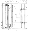
- figure 1 is a diagrammatic lateral view of the machine of the invention, seen from a direction orthogonal to the travelling direction of the product to be packaged above the consecutive pair of conveyor belts;
- figure 2 is a top view of figure 1, with one of the portal-shaped frame translated in lateral position with respect to the machine;
- figure 3 is a front view of the machine of fig. 1;
- fig. 4 is the front view of one of the laterally sliding coil-holding frames;
- figure 5 is a side view of the frame of fig. 4.
- With reference to the aforementioned figures, the improved machine of the invention comprises a consecutive aligned pair of conveyor belts (1 and 2) and a wrapping station (3) between the first (1) and the second (2) conveyor belt.
- The first conveyor belt (1) has a telescopic section (1 a) that in forward position is parallel to the second belt (2) in a coplanar way, while in backward position uncovers a large compartment (4) below the travel plane of the product (P).
- The front border of the telescopic section (1a) of the first conveyor belt (1) is laterally provided with an opposite pair of uprights (1 b) that support a transversal bar (1 c). During extension of the telescopic section (1 a), the telescopic bar (1 c) intercepts and pushes the section of wrapping tape (N) to the wrapping station (3), while the lower coil (10) is momentarily lowered in working position.
- The wrapping station (3) is transversally enclosed by two fixed portals (5 and 6) that extend astride the ending section of the first conveyor (1) and the initial section of the second conveyor (2), respectively acting as support structure for the frames of the said conveyor belts (1 and 2).
- The fixed portals (5 and 6) are stiffened by means of corresponding crosspieces (T) connecting their bases.
- The empty space between the two fixed portals (5 and 6) is occupied by a consecutive series of identical portal-shaped frames (7) that extend transversally astride the space in which the telescopic section (1a) of the conveyor belt (1) operates.
- Each frame (7) supports a different wrapping tape (N) wrapped on a pair of coils, the upper coil (8) resting on a parallel pair of unwrapping rollers (9) and the lower coil (10) equally resting on a parallel pair of rollers (11).
- The two pairs of parallel rollers (9 and 11) transversally extend between corresponding opposite pairs of upper (9a) and lower (11 a) carriages that slide vertically along the lateral columns (7a) of the portal-shaped frames (7).
- More precisely, the two lower carriages (11 a) are driven in alternate vertical travels by a driving chain (12) of a gear assembly, whose driving geared motor (13) is located in external position at the base of one column (7a).
- In view of the above, each lower coil (10) can be automatically transferred from the raised idle position (PS) to the lowered working position (PA), in which it rests inside the compartment (4) under the telescopic section (1 a) of the first conveyor belt (1), as shown in fig. 1 with reference to the lower coil (10) in first position along the travelling direction of the tape (1).
- In fig. 4 numeral (14) indicates the geared motor designed to drag into rotation the parallel pair of unwrapping rollers (9) used to unwrap the upper coil (8) of each overlapped pair of coils (8 and 10).
- Although it can slide along columns (7a), the opposite pair of upper carriages (9) is blocked on top of the columns (7a) to which they are coupled by means of a stopping pin actuated by a jack (9b), until it is not necessary to perform maintenance on the upper coil (8).
- Each portal-shaped frame (7) is provided with ground sliding means, i.e. wheels (7b) in this case, to translate laterally according to a direction orthogonal to the travel direction of the product on the conveyor belts (1 and 2), it being evident that translation is only possible after retracting the telescopic section (1 a) of the first conveyor belt (1).
- The frame (7) is translated laterally only to extract the frame (7) from the wrapping station (3) to change the coils (8 and 10) or perform other maintenance or repair operations on the components of the frame (7).
- Since the lateral translation of each frame (7) can be performed for a distance sufficient to extract the frame (7) from the wrapping station (3) completely, it appears evident that until the frame (7) is parked next to the wrapping station (3), packaging can continue with unchanged speed and method, using the wrapping tapes (N) available on the other portal-shaped frames (7), that is to say the frames (7) in working position.
- The operator (A) can easily intervene on coils (8 and 10) of the laterally extracted frame (7), after lowering the coils (8 and 10) to the ground, using the support carriages (9a and 11a) that slide along the columns (7a); the operator simply needs to actuate the jack (9b) to retract the stopping pin of the upper carriage (9a), which is supported by the lower carriage (11a).
- Now the operator can actuate the geared motor (13) to make the driving chain (12) drag the lower carriage (11a) to the lowered position (PA), together with the upper carriage (9a) that rests on the lower carriage (11 a).
- Return rollers (15) extend transversally between columns (7a) of each frame (7) and are supported by the opposite pair of upper carriages (9a), used to partially wind up the section of tape (N) coming from the upper coil (8) and going to the lower coil (10).
- In the enclosed figures numeral (16) indicates the device used to cut and seal the wrapping tape once the product is completely wrapped.
- The device (16) of known type is actuated by a geared motor (17) and mounted on the fixed portal (6) with the possibility of making alternate vertical travels.
Claims (6)
- Improved automatic packaging machine with multiple wrapping tapes of different width, of the type comprising:- one consecutive aligned pair of conveyor belts (1 and 2), of which the first conveyor belt (1) has a telescopic section (1a) that in forward position is parallel to the second belt (2) in a coplanar way, while in backward position uncovers a large compartment (4) below the travel plane of the product (P);- one wrapping station (3) between the first (1) and the second (2) conveyor belt;- one transversal bar (1c) capable of making alternate horizontal travels through the wrapping station (3) at a height above the travelling plane of the product (P) on the belt (1, 1a);characterised in that it comprises a consecutive series of identical portal-shaped frames (7) that transversally extend astride the space in which the telescopic section (1a) operates, with each frame being capable of sliding laterally and supporting a wrapping tape (N) wrapped on a pair of coils, one upper coil (8) and one lower coil (10), capable of making alternate vertical travels from a raised idle position (PS) to a lowered working position (PA), in which the lower coil (10) is positioned in the compartment (4) under the telescopic section (1a) of the first conveyor belt (1).
- Machine as defined in claim 1, characterised in that in each frame (7) the lower coil (10) rests on a parallel pair of rollers (11), supported at the ends by an opposite pair of lower carriages (11a) that slide vertically along the lateral columns (7a) of the frame (7) and are driven in vertical travels by a driving chain (12) of a gear assembly, whose driving geared motor (13) is located in external position at the base of one column (7a).
- Machine as defined in above claims, characterised in that in each frame (7) the upper coil (8) rests on a parallel pair of unwrapping rollers (9), actuated by a geared motor (14) and supported at opposite ends by an opposite pair of upper carriages (9a) that slide vertically along the lateral columns (7a), on top of which they are stopped by a stopping pin actuated by a jack (9).
- Machine as defined in one or more of above claims, characterised in that return rollers (15) extend transversally between the columns (7a) of each frame (7) and are supported by the opposite pair of upper carriages (9a), used to partially wind up the section of tape (N) coming from the upper coil (8) and going to the lower coil (10).
- Machine as defined in claim 1, characterised in that the transversal bar (1c) is fixed to the top of a pair of uprights (1b) fixed on the two sides of the telescopic section (1a) and on its front border.
- Machine as defined in one or more of above claims, characterised in that the wrapping station (3), in which the consecutive series of frames (7) is contained, is transversally enclosed by two fixed portals (5) and (6) that extend astride the ending section of the first conveyor (1) and the initial section of the second conveyor (2), respectively acting as support structure for the frames of the said conveyor belts (1 and 2).
Applications Claiming Priority (1)
| Application Number | Priority Date | Filing Date | Title |
|---|---|---|---|
| ITMC20040141 ITMC20040141A1 (en) | 2004-11-29 | 2004-11-29 | PERFECT MACHINE FOR AUTOMATIC PACKAGING OF PRODUCTS IN GENERAL WITH WRAPPING TAPES. |
Publications (1)
| Publication Number | Publication Date |
|---|---|
| EP1661808A1 true EP1661808A1 (en) | 2006-05-31 |
Family
ID=35697118
Family Applications (1)
| Application Number | Title | Priority Date | Filing Date |
|---|---|---|---|
| EP05425837A Withdrawn EP1661808A1 (en) | 2004-11-29 | 2005-11-25 | Machine for packaging products with wrapping film |
Country Status (2)
| Country | Link |
|---|---|
| EP (1) | EP1661808A1 (en) |
| IT (1) | ITMC20040141A1 (en) |
Cited By (1)
| Publication number | Priority date | Publication date | Assignee | Title |
|---|---|---|---|---|
| FR2948922A1 (en) * | 2009-08-04 | 2011-02-11 | Techman Mecanisation | Products i.e. parallelepipedic shaped window joinery works, packing installation, has conveying device for conveying products on edge along conveying direction, and movable module moving between active position and isolated position |
Citations (6)
| Publication number | Priority date | Publication date | Assignee | Title |
|---|---|---|---|---|
| EP0183676A1 (en) * | 1984-11-30 | 1986-06-04 | Adolf Reker Maschinenfabrik und Baggerbau GmbH | Device for packaging goods in a shrink foil |
| US5205505A (en) * | 1990-07-31 | 1993-04-27 | Focke & Co. | Device for supplying packaging machines with packaging material |
| EP0939031A2 (en) * | 1998-02-25 | 1999-09-01 | di Giunti Renzo, Erregi | Automatic packing machine with several different wrapping tapes of various widths |
| EP1094007A1 (en) * | 1999-10-19 | 2001-04-25 | Resta S.R.L. | Device for automatically changing the roll for feeding the wrapping film in a packaging machine |
| ES2199007A1 (en) * | 2001-01-22 | 2004-02-01 | Construcciones Metalicas Jose | Machine for automatic packaging with plastic sheets. (Machine-translation by Google Translate, not legally binding) |
| EP1602581A2 (en) * | 2004-05-26 | 2005-12-07 | AETNA GROUP S.p.A. | Apparatus for packaging products with heat-shrink film |
-
2004
- 2004-11-29 IT ITMC20040141 patent/ITMC20040141A1/en unknown
-
2005
- 2005-11-25 EP EP05425837A patent/EP1661808A1/en not_active Withdrawn
Patent Citations (6)
| Publication number | Priority date | Publication date | Assignee | Title |
|---|---|---|---|---|
| EP0183676A1 (en) * | 1984-11-30 | 1986-06-04 | Adolf Reker Maschinenfabrik und Baggerbau GmbH | Device for packaging goods in a shrink foil |
| US5205505A (en) * | 1990-07-31 | 1993-04-27 | Focke & Co. | Device for supplying packaging machines with packaging material |
| EP0939031A2 (en) * | 1998-02-25 | 1999-09-01 | di Giunti Renzo, Erregi | Automatic packing machine with several different wrapping tapes of various widths |
| EP1094007A1 (en) * | 1999-10-19 | 2001-04-25 | Resta S.R.L. | Device for automatically changing the roll for feeding the wrapping film in a packaging machine |
| ES2199007A1 (en) * | 2001-01-22 | 2004-02-01 | Construcciones Metalicas Jose | Machine for automatic packaging with plastic sheets. (Machine-translation by Google Translate, not legally binding) |
| EP1602581A2 (en) * | 2004-05-26 | 2005-12-07 | AETNA GROUP S.p.A. | Apparatus for packaging products with heat-shrink film |
Cited By (1)
| Publication number | Priority date | Publication date | Assignee | Title |
|---|---|---|---|---|
| FR2948922A1 (en) * | 2009-08-04 | 2011-02-11 | Techman Mecanisation | Products i.e. parallelepipedic shaped window joinery works, packing installation, has conveying device for conveying products on edge along conveying direction, and movable module moving between active position and isolated position |
Also Published As
| Publication number | Publication date |
|---|---|
| ITMC20040141A1 (en) | 2005-02-28 |
Similar Documents
| Publication | Publication Date | Title |
|---|---|---|
| US9580194B2 (en) | Wrapping machine | |
| US8424271B2 (en) | Process for wrapping loads, in particular palletised loads, and relative system | |
| CN113173279B (en) | Rotary translation packaging equipment and packaging method thereof | |
| JP5453555B2 (en) | Board material loading / unloading shelf equipment | |
| US20080229716A1 (en) | Film wrapping machine simultaneously utilizing two film carriage assemblies | |
| EP2174871B1 (en) | Method and apparatus for packaging a mattress in a package composed of multiple wrappings arranged one inside the other | |
| CN110944911B (en) | Wrapping machine | |
| EP1661808A1 (en) | Machine for packaging products with wrapping film | |
| WO2008117161A2 (en) | Apparatus for positioning a covering sheet on top of a product | |
| CN116002565A (en) | Logistics storage goods shelf lifting device with dynamic balance adjusting function | |
| EP1602581B1 (en) | Apparatus for packaging products with heat-shrink film | |
| CN109455355B (en) | Full-automatic vanning line | |
| CN212268514U (en) | Traditional chinese medicine draws mobile platform for workshop | |
| CN113060332A (en) | Full-automatic encapsulation equipment of gloves | |
| CN220010228U (en) | Automatic packing device of tobacco rod | |
| CN218578135U (en) | Automatic basket machine of packing of formula domestic fungus package is transported in batches | |
| CN220182669U (en) | Edible fungi material basket loading machine | |
| CN215046988U (en) | Defective paper roll stacker | |
| CN212501191U (en) | Rotary translation baling equipment | |
| CN112278366B (en) | Paper receiving and packaging mechanism of double-layer paper packaging machine | |
| CN220096742U (en) | Steel binding device for steel production | |
| CN113428398B (en) | Pallet anti-falling goods bundling equipment and bundling method | |
| CN214086477U (en) | Novel automatic box arranging device | |
| KR0163051B1 (en) | Article packaging machine | |
| KR200183946Y1 (en) | Device for changing sheet box |
Legal Events
| Date | Code | Title | Description |
|---|---|---|---|
| PUAI | Public reference made under article 153(3) epc to a published international application that has entered the european phase |
Free format text: ORIGINAL CODE: 0009012 |
|
| AK | Designated contracting states |
Kind code of ref document: A1 Designated state(s): AT BE BG CH CY CZ DE DK EE ES FI FR GB GR HU IE IS IT LI LT LU LV MC NL PL PT RO SE SI SK TR |
|
| AX | Request for extension of the european patent |
Extension state: AL BA HR MK YU |
|
| 17P | Request for examination filed |
Effective date: 20061121 |
|
| 17Q | First examination report despatched |
Effective date: 20070103 |
|
| AKX | Designation fees paid |
Designated state(s): DE ES FR IT |
|
| STAA | Information on the status of an ep patent application or granted ep patent |
Free format text: STATUS: THE APPLICATION IS DEEMED TO BE WITHDRAWN |
|
| 18D | Application deemed to be withdrawn |
Effective date: 20070515 |