EP1661748A2 - Pump unit and hydrostatic transmission - Google Patents
Pump unit and hydrostatic transmission Download PDFInfo
- Publication number
- EP1661748A2 EP1661748A2 EP05022808A EP05022808A EP1661748A2 EP 1661748 A2 EP1661748 A2 EP 1661748A2 EP 05022808 A EP05022808 A EP 05022808A EP 05022808 A EP05022808 A EP 05022808A EP 1661748 A2 EP1661748 A2 EP 1661748A2
- Authority
- EP
- European Patent Office
- Prior art keywords
- main body
- hydraulic
- hydraulic fluid
- line
- pto
- Prior art date
- Legal status (The legal status is an assumption and is not a legal conclusion. Google has not performed a legal analysis and makes no representation as to the accuracy of the status listed.)
- Withdrawn
Links
- 230000005540 biological transmission Effects 0.000 title claims description 62
- 230000002706 hydrostatic effect Effects 0.000 title claims description 34
- 239000012530 fluid Substances 0.000 claims abstract description 508
- 230000007246 mechanism Effects 0.000 claims abstract description 73
- 238000004891 communication Methods 0.000 claims description 39
- 238000000605 extraction Methods 0.000 claims description 14
- 230000009471 action Effects 0.000 claims description 6
- 238000006073 displacement reaction Methods 0.000 description 7
- 230000007257 malfunction Effects 0.000 description 5
- 230000007935 neutral effect Effects 0.000 description 5
- 238000010586 diagram Methods 0.000 description 4
- 210000003734 kidney Anatomy 0.000 description 4
- 230000008859 change Effects 0.000 description 3
- 239000002184 metal Substances 0.000 description 3
- 230000009467 reduction Effects 0.000 description 3
- 208000032370 Secondary transmission Diseases 0.000 description 2
- 230000002159 abnormal effect Effects 0.000 description 2
- 244000145845 chattering Species 0.000 description 2
- 238000001816 cooling Methods 0.000 description 2
- 238000013016 damping Methods 0.000 description 2
- 238000004519 manufacturing process Methods 0.000 description 2
- 230000002265 prevention Effects 0.000 description 2
- 238000005086 pumping Methods 0.000 description 2
- 238000011144 upstream manufacturing Methods 0.000 description 2
- 244000025254 Cannabis sativa Species 0.000 description 1
- 230000010485 coping Effects 0.000 description 1
- 230000000694 effects Effects 0.000 description 1
- 230000002708 enhancing effect Effects 0.000 description 1
- 230000004048 modification Effects 0.000 description 1
- 238000012986 modification Methods 0.000 description 1
- 238000000465 moulding Methods 0.000 description 1
Images








Classifications
-
- F—MECHANICAL ENGINEERING; LIGHTING; HEATING; WEAPONS; BLASTING
- F04—POSITIVE - DISPLACEMENT MACHINES FOR LIQUIDS; PUMPS FOR LIQUIDS OR ELASTIC FLUIDS
- F04B—POSITIVE-DISPLACEMENT MACHINES FOR LIQUIDS; PUMPS
- F04B1/00—Multi-cylinder machines or pumps characterised by number or arrangement of cylinders
- F04B1/12—Multi-cylinder machines or pumps characterised by number or arrangement of cylinders having cylinder axes coaxial with, or parallel or inclined to, main shaft axis
- F04B1/20—Multi-cylinder machines or pumps characterised by number or arrangement of cylinders having cylinder axes coaxial with, or parallel or inclined to, main shaft axis having rotary cylinder block
- F04B1/22—Multi-cylinder machines or pumps characterised by number or arrangement of cylinders having cylinder axes coaxial with, or parallel or inclined to, main shaft axis having rotary cylinder block having two or more sets of cylinders or pistons
-
- F—MECHANICAL ENGINEERING; LIGHTING; HEATING; WEAPONS; BLASTING
- F04—POSITIVE - DISPLACEMENT MACHINES FOR LIQUIDS; PUMPS FOR LIQUIDS OR ELASTIC FLUIDS
- F04B—POSITIVE-DISPLACEMENT MACHINES FOR LIQUIDS; PUMPS
- F04B23/00—Pumping installations or systems
- F04B23/04—Combinations of two or more pumps
- F04B23/06—Combinations of two or more pumps the pumps being all of reciprocating positive-displacement type
-
- F—MECHANICAL ENGINEERING; LIGHTING; HEATING; WEAPONS; BLASTING
- F04—POSITIVE - DISPLACEMENT MACHINES FOR LIQUIDS; PUMPS FOR LIQUIDS OR ELASTIC FLUIDS
- F04B—POSITIVE-DISPLACEMENT MACHINES FOR LIQUIDS; PUMPS
- F04B23/00—Pumping installations or systems
- F04B23/04—Combinations of two or more pumps
- F04B23/08—Combinations of two or more pumps the pumps being of different types
- F04B23/10—Combinations of two or more pumps the pumps being of different types at least one pump being of the reciprocating positive-displacement type
- F04B23/106—Combinations of two or more pumps the pumps being of different types at least one pump being of the reciprocating positive-displacement type being an axial piston pump
-
- F—MECHANICAL ENGINEERING; LIGHTING; HEATING; WEAPONS; BLASTING
- F16—ENGINEERING ELEMENTS AND UNITS; GENERAL MEASURES FOR PRODUCING AND MAINTAINING EFFECTIVE FUNCTIONING OF MACHINES OR INSTALLATIONS; THERMAL INSULATION IN GENERAL
- F16D—COUPLINGS FOR TRANSMITTING ROTATION; CLUTCHES; BRAKES
- F16D31/00—Fluid couplings or clutches with pumping sets of the volumetric type, i.e. in the case of liquid passing a predetermined volume per revolution
- F16D31/02—Fluid couplings or clutches with pumping sets of the volumetric type, i.e. in the case of liquid passing a predetermined volume per revolution using pumps with pistons or plungers working in cylinders
-
- F—MECHANICAL ENGINEERING; LIGHTING; HEATING; WEAPONS; BLASTING
- F16—ENGINEERING ELEMENTS AND UNITS; GENERAL MEASURES FOR PRODUCING AND MAINTAINING EFFECTIVE FUNCTIONING OF MACHINES OR INSTALLATIONS; THERMAL INSULATION IN GENERAL
- F16D—COUPLINGS FOR TRANSMITTING ROTATION; CLUTCHES; BRAKES
- F16D31/00—Fluid couplings or clutches with pumping sets of the volumetric type, i.e. in the case of liquid passing a predetermined volume per revolution
- F16D31/08—Control of slip
-
- F—MECHANICAL ENGINEERING; LIGHTING; HEATING; WEAPONS; BLASTING
- F16—ENGINEERING ELEMENTS AND UNITS; GENERAL MEASURES FOR PRODUCING AND MAINTAINING EFFECTIVE FUNCTIONING OF MACHINES OR INSTALLATIONS; THERMAL INSULATION IN GENERAL
- F16H—GEARING
- F16H61/00—Control functions within control units of change-speed- or reversing-gearings for conveying rotary motion ; Control of exclusively fluid gearing, friction gearing, gearings with endless flexible members or other particular types of gearing
- F16H61/38—Control of exclusively fluid gearing
- F16H61/40—Control of exclusively fluid gearing hydrostatic
- F16H61/4078—Fluid exchange between hydrostatic circuits and external sources or consumers
- F16H61/4139—Replenishing or scavenging pumps, e.g. auxiliary charge pumps
-
- B—PERFORMING OPERATIONS; TRANSPORTING
- B60—VEHICLES IN GENERAL
- B60K—ARRANGEMENT OR MOUNTING OF PROPULSION UNITS OR OF TRANSMISSIONS IN VEHICLES; ARRANGEMENT OR MOUNTING OF PLURAL DIVERSE PRIME-MOVERS IN VEHICLES; AUXILIARY DRIVES FOR VEHICLES; INSTRUMENTATION OR DASHBOARDS FOR VEHICLES; ARRANGEMENTS IN CONNECTION WITH COOLING, AIR INTAKE, GAS EXHAUST OR FUEL SUPPLY OF PROPULSION UNITS IN VEHICLES
- B60K17/00—Arrangement or mounting of transmissions in vehicles
- B60K17/28—Arrangement or mounting of transmissions in vehicles characterised by arrangement, location, or type of power take-off
-
- F—MECHANICAL ENGINEERING; LIGHTING; HEATING; WEAPONS; BLASTING
- F16—ENGINEERING ELEMENTS AND UNITS; GENERAL MEASURES FOR PRODUCING AND MAINTAINING EFFECTIVE FUNCTIONING OF MACHINES OR INSTALLATIONS; THERMAL INSULATION IN GENERAL
- F16H—GEARING
- F16H39/00—Rotary fluid gearing using pumps and motors of the volumetric type, i.e. passing a predetermined volume of fluid per revolution
- F16H39/04—Rotary fluid gearing using pumps and motors of the volumetric type, i.e. passing a predetermined volume of fluid per revolution with liquid motor and pump combined in one unit
- F16H39/06—Rotary fluid gearing using pumps and motors of the volumetric type, i.e. passing a predetermined volume of fluid per revolution with liquid motor and pump combined in one unit pump and motor being of the same type
- F16H39/08—Rotary fluid gearing using pumps and motors of the volumetric type, i.e. passing a predetermined volume of fluid per revolution with liquid motor and pump combined in one unit pump and motor being of the same type each with one main shaft and provided with pistons reciprocating in cylinders
- F16H39/10—Rotary fluid gearing using pumps and motors of the volumetric type, i.e. passing a predetermined volume of fluid per revolution with liquid motor and pump combined in one unit pump and motor being of the same type each with one main shaft and provided with pistons reciprocating in cylinders with cylinders arranged around, and parallel or approximately parallel to the main axis of the gearing
- F16H39/14—Rotary fluid gearing using pumps and motors of the volumetric type, i.e. passing a predetermined volume of fluid per revolution with liquid motor and pump combined in one unit pump and motor being of the same type each with one main shaft and provided with pistons reciprocating in cylinders with cylinders arranged around, and parallel or approximately parallel to the main axis of the gearing with cylinders carried in rotary cylinder blocks or cylinder-bearing members
Definitions
- the present invention relates to a pump unit and a hydrostatic transmission.
- an auxiliary pump main body which is operatively driven by the driving power source in order to supply hydraulic fluid for replenishing to the pair of hydraulic fluid lines and supply hydraulic fluid for operating to the PTO clutch mechanism provided in the PTO transmission mechanism (refer to, for example, JP-A 2003-291674).
- a conventional pump unit or conventional hydrostatic transmission includes a suction line for fluidly communicating between a suction port of the auxiliary pump main body and a fluid reservoir, a discharge line which is fluidly connected to a discharge port of the auxiliary pump main body, a charge line which is branched from the discharge line via a pressure-reducing valve for supplying hydraulic fluid for replenishing to the pair of hydraulic fluid lines, and a PTO hydraulic fluid line which is branched from the discharge line via the pressure-reducing valve for supplying hydraulic fluid for operating to the aforementioned PTO clutch mechanism.
- the pressure-reducing valve is configured to be capable of defining the hydraulic pressure in the charge line to a predetermined hydraulic pressure with a hydraulic pressure setting spring placed within the spring chamber and, as previously described, a conventional pump unit or hydrostatic transmission is configured such that the PTO hydraulic fluid line is supplied with hydraulic fluid from the spring chamber of the pressure-reducing valve.
- a PTO relief valve for setting the hydraulic pressure in the PTO clutch mechanism, in addition to a switching valve for switching between supply and interruption of hydraulic fluid to the PTO clutch mechanism. Therefore, when the PTO clutch mechanism is disengaged, the PTO hydraulic fluid line is at a natural pressure that is communicated with the fluid reservoir, while when the PTO clutch mechanism is engaged, it is set to an operational pressure defined by the PTO relief valve.
- pump units as described above may include a pair of hydraulic pump main bodies.
- Such pump units are configured to be capable of transmitting a rotational power from a driving power source which is operatively connected thereto to first and second hydraulic motor units for driving the left and right driving wheels through a pair of first hydraulic fluid lines and a pair of second hydraulic fluid lines.
- the pair of hydraulic pump main bodies and the pair of hydraulic motor units form a pair of HSTs for individually driving the pair of left and right driving wheels.
- Such output differences between the pair of hydraulic motor units may cause a so-called wandering phenomenon that the vehicle meanders even though the vehicle is manipulated such that it linearly moves.
- the PTO hydraulic fluid line and the charge line are fluidly connected to the primary side and a secondary side of the pressure-reducing valve, respectively.
- the pump unit further includes a drain line which fluidly connects a secondary side of the resistance valve to the fluid reservoir.
- the drain line is so configured to have an oil cooler inserted therein.
- the pump unit may include a drain line which fluidly connects the secondary side of the resistance valve to the fluid reservoir; and an external hydraulic fluid extraction line which is branched off from the drain line.
- the pump unit further includes an external hydraulic pressure relief valve which has a primary side fluidly connected to the discharge line.
- the hydraulic pressure in the external hydraulic fluid extraction line is set by the external hydraulic pressure relief valve.
- the pump unit further includes a return line which has a first end fluidly connected to the discharge line and a second end fluidly connected to the suction line.
- the external hydraulic pressure relief valve is inserted in the return line.
- the PTO hydraulic fluid line may be fluidly connected to the primary side of the pressure-reducing valve through an orifice.
- a hydrostatic transmission for vehicle traveling which non-stepwisely changes a speed of a rotational power from a driving power source which is operatively connected thereto by means of hydraulic actions.
- the PTO hydraulic fluid line and the charge line are fluidly connected to the primary side and a secondary side of the pressure-reducing valve, respectively.
- the PTO hydraulic fluid line may be fluidly connected to the primary side of the pressure-reducing valve through an orifice.
- the housing main body includes a first end-face portion provided with the opening, a second end-face portion positioned at the opposite side from the first end-face portion with respect to the direction of the rotation axis of the hydraulic pump main body, and a wall portion extending in the direction of the rotation axis of the hydraulic pump main body between the first end-face portion and the second end-face portion.
- the accumulator is incorporated within the first end-face portion or the second end-face portion such that its axis is substantially orthogonal to the direction of the rotation axis of the hydraulic pump main body.
- a hydrostatic transmission which non-stepwisely changes a speed of a rotational power from a driving power source which is operatively connected thereto by means of hydraulic actions.
- the hydrostatic transmission includes: an input shaft which is operatively connected to the driving power source; a hydraulic pump main body which is operatively driven by the input shaft; a hydraulic motor main body which is fluidly connected to the hydraulic pump main body; a motor shaft which is rotated and driven by the hydraulic motor main body; a PTO shaft which is operatively driven by the input shaft; a PTO clutch mechanism which is inserted in a transmission path from the input shaft to the PTO shaft; an auxiliary pump main body; a housing which accommodates the hydraulic pump main body, the hydraulic motor main body and the PTO clutch mechanism; a discharge line which is fluidly connected to a discharge port of the auxiliary pump main body; a PTO hydraulic fluid line which is fluidly connected to the discharge line and supplies hydraulic fluid to the PTO clutch mechanism; a PTO relief valve which sets the hydraulic pressure in the PTO hydraulic fluid line; and an accumulator which is inserted in the PTO hydraulic fluid line and gradually raises the hydraulic pressure in the PTO hydraulic fluid line to the pressure set by the PTO relief valve.
- the housing includes: a housing main body which is provided with an opening for allowing the hydraulic pump main body and the hydraulic motor main body to pass therethrough, the opening being provided at one side in the direction of the rotation axis of the hydraulic pump main body; and a port block which is detachably connected to the housing main body such that it abuts the hydraulic pump main body and the hydraulic motor main body, and closes the opening of the housing main body in a liquid-tight manner, the port block being provided with a pair of hydraulic fluid passages which fluidly connect the hydraulic pump main body and the hydraulic motor main body to each other.
- the housing main body includes a first end-face portion provided with the opening, a second end-face portion positioned at the opposite side from the first end-face portion with respect to the direction of the rotation axis of the hydraulic pump main body and a wall portion extending in the direction of the rotation axis of the hydraulic pump main body between the first end-face portion and the second end-face portion.
- the accumulator may be incorporated within the wall portion such that its axis is along the direction of the rotation axis of the hydraulic pump main body.
- the accumulator is incorporated within the first end-face portion or the second end-face portion such that its axis is substantially orthogonal to the direction of the rotation axis of the hydraulic pump main body.
- the pump unit includes: an input shaft which is operatively connected to the driving power source; first and second hydraulic pump main bodies which are operatively driven by the input shaft and are fluidly connected to the first and second motor units through the pair of first hydraulic fluid lines and the pair of second hydraulic fluid lines; a housing main body which surrounds the first and second hydraulic pump main bodies; a port block which abuts and supports the first and second hydraulic pump main bodies, and defines the accommodating space for the first and second hydraulic pump main bodies in cooperation with the housing main body; and a communication line which communicates between a forward-movement high-pressure side first hydraulic fluid line, which is brought into higher pressure during forward movement, out of the pair of first hydraulic fluid lines and a forward-movement high-pressure side second hydraulic fluid line, which is brought into higher pressure during forward movement, out of the pair of second hydraulic fluid lines, the communication line having an orifice inserted therein.
- the port block is provided with a pair of first hydraulic fluid passages and a pair of second hydraulic fluid passages which form a part of the pair of first hydraulic fluid lines and the pair of second hydraulic fluid lines, respectively, and the communication line is configured to communicate between a forward-movement high-pressure side first hydraulic fluid passage, which is brought into higher pressure during forward movement, out of the pair of first hydraulic fluid passages and a forward-movement high-pressure side second hydraulic fluid passage, which is brought into higher pressure during forward movement, out of the pair of second hydraulic fluid passages.
- the pair of first hydraulic fluid passages and the pair of second hydraulic fluid passages are formed to be substantially parallel to each other, and the communication line has a communication fluid passage formed in the port block such that it is orthogonal to the pair of first hydraulic fluid passages and the pair of second hydraulic fluid passages.
- the communication line has a conduit which is detachably connected to the port block such that it communicates the forward-movement high-pressure side first hydraulic fluid passage and the forward-movement high-pressure side second hydraulic fluid passage to each other.
- the pump unit 100 includes a PTO braking mechanism 600B which operates in conjunction with the PTO clutch mechanism 600A.
- the PTO braking mechanism 600B is provided in order to prevent the PTO shaft 610 from being continuously rotated due to an inertial force when the power to the PTO shaft 610 from the input shaft 220 is shutoff.
- the pair of first and second hydraulic pump main bodies 300a and 300b are fluidly connected to a pair of first and second hydraulic motor units 10a and 10b which serve as the aforementioned actuator through the pair of first and second hydraulic fluid lines 400a and 400b, respectively.
- the first hydraulic pump main body 300a and the first hydraulic motor unit 10a form a first HST for vehicle-traveling which drives one of a pair of driving wheels 50 with variable rotational speeds.
- the second hydraulic pump main body 300b and the second hydraulic motor unit 10b form a second HST for vehicle-traveling which drives the other one of the pair of driving wheels 50 with variable rotational speeds.
- the housing 200 includes a housing main body 210 which accommodates the first and second hydraulic pump main bodies 300a and 300b and the PTO clutch mechanism 600A, a center section (port block) 360 which is detachably connected to the housing main body 210 and is provided with fluid passages fluidly communicated with the first and second hydraulic pump main bodies 300a and 300b, and a cover member 250 which is detachably connected to the housing main body 210 at the opposite side from the port block 360 in the direction of the rotation axes of the hydraulic pump main bodies 300a and 300b.
- a housing main body 210 which accommodates the first and second hydraulic pump main bodies 300a and 300b and the PTO clutch mechanism 600A
- a center section (port block) 360 which is detachably connected to the housing main body 210 and is provided with fluid passages fluidly communicated with the first and second hydraulic pump main bodies 300a and 300b
- a cover member 250 which is detachably connected to the housing main body 210 at the opposite side from the port block 360 in the direction of the rotation
- first and second hydraulic pump main bodies 300a and 300b are accommodated within the housing 200 such that the directions of their rotation axes are in parallel with each other along the fore-to-aft direction of the vehicle.
- the PTO shaft 610 is also supported by the housing 200 such that the rotation axis thereof is in parallel with the direction of the rotation axes of the first and second hydraulic pump main bodies 300a and 300b.
- the first end-face portion 211 includes a first opening 211 a which allows the first and second hydraulic pump main bodies 300a and 300b to pass therethrough, at the one side in the widthwise direction of the housing main body 210.
- first opening 211a is liquid-tightly sealed with the port block 360.
- the housing 200 is configured to define a pump accommodating space 201 for accommodating the first and second hydraulic pump main bodies 300a and 300b between the port block 360 and the second end-face portion 212 (see Fig. 2).
- the second end-face portion 212 includes a swash plate receiving portion 212a having a concave arc-shaped guiding surface for slidably abutting and supporting a movable swash plate 353 which will be described later of the first and second hydraulic pump main bodies 300a and 300b at the position corresponding to the pump accommodating space 201, and a second opening 212b which allows the PTO clutch mechanism 600A to pass therethrough at the other side of the housing 200 in the vehicle-widthwise direction (see Fig. 2).
- the second opening 212b is liquid-tightly sealed with the cover member 250.
- the housing 200 is configured to define a PTO clutch accommodating space 202 for accommodating the PTO clutch mechanism 600A between the cover member 250 and the first end-face portion 211.
- the internal space of the housing 200 which is defined by the port block 360 and the second end-face portion 212, at one side in the widthwise direction is utilized as the pump accommodating space 201 while the internal space of the housing 200, which is defined by the cover member 250 and the first end-face portion 211, at the other side in the widthwise direction is utilized as the PTO clutch accommodating space 202.
- the swash plate receiving portion 212a is formed integrally with the housing main body 210 and, accordingly, the first opening 211a which allows the first and second hydraulic pump main bodies 300a and 300b to pass therethrough and the second opening 212b which allows the PTO clutch mechanism 600A to pass therethrough are provided at one side and the other side in the direction of the rotation axes of the first and second hydraulic pump main bodies 300a and 300b.
- the swash plate receiving portion 212a may be formed separately from the housing main body 210.
- the swash plate receiving portion 212a By forming the swash plate receiving portion 212a separately from the housing main body 210, it is possible to eliminate the necessity of the second end-face portion 212. Consequently, when molding the housing main body 210, it is possible to pull out the respective molds for forming the hydraulic pump housing portion 201 and the PTO clutch housing portion 202 in the same direction.
- the cover member 250 is detachably connected to the housing main body 210 so as to form a transmission mechanism accommodating space 203 (see Fig. 2) for accommodating the transmission mechanism 280 between the cover member 250 and the second end-face portion 212 of the housing main body 210.
- the second end-face portion 212 may be provided with a communication channel 215 which allows fluid to freely flow between the hydraulic pump accommodating space 201 and the transmission mechanism accommodating space 203.
- the input shaft 220 is supported by the housing 200 in a state where its first end at the upstream side in the direction of transmission is outwardly extended from the housing 200 so as to be operatively connected to the driving power source.
- the first hydraulic pump main body 300a is of an axial piston type as illustrated in Fig. 2 and Fig. 3.
- the output-adjusting member 340a can be manipulated from outside using a control shaft 350a which is connected thereto through an arm 351a (see Fig. 3).
- the pump unit 100 is configured to be capable of supplying fluid discharged from the auxiliary pump main body 510 to the pair of first hydraulic fluid lines 400a and the pair of second hydraulic fluid lines 400b as charge fluid, and also capable of supplying the discharged fluid to the PTO clutch mechanism 600A as operation fluid.
- the pump unit 100 includes a suction line 550 which has a first end fluidly connected to a fluid reservoir (the internal space of the housing 200 in this embodiment) and a second end fluidly connected to a suction port of the auxiliary pump main body 510, a discharge line 560 which is fluidly connected to the discharge port of the auxiliary pump main body 510, a charge line 420 which supplies a part of the hydraulic fluid from the discharge line 560 to the pair of the first hydraulic fluid lines 400a and the pair of second hydraulic fluid lines 400b through a check valve 425, a PTO hydraulic fluid line 470 which supplies a part of the hydraulic fluid from the discharge line 560 to the PTO clutch mechanism 600A through a PTO relief valve 478, a pressure-reducing valve 530 which has a primary side fluidly connected to the discharge line 560, and a resistance valve 540 which is fluidly connected to the primary side of the pressure-reducing valve 530.
- a suction line 550 which has a first end fluidly connected to a fluid reservoir (the internal
- the PTO hydraulic fluid line 470 and the charge line 420 are fluidly connected to the primary side and a secondary side of the pressure-reducing valve 530, respectively, to enable maintaining the hydraulic pressure in the charge line 420 constant regardless of whether or not the PTO clutch mechanism 600A is engaged or disengaged, thus preventing the malfunction of fluctuations in the operation torques of the output-adjusting members 350a and 350b of the first and second hydraulic pump main bodies 300a and 300b due to the change of the state of the hydraulic clutch mechanism 600A, which has been conventionally occurred.
- Such hydraulic pressure fluctuations in the charge line induce back pressures acting on the first piston unit 330a, thus causing fluctuations in the operation torques of the output-adjusting members in the hydraulic pump main bodies.
- the hydraulic pressure in the charge line rises, which causes an increase of the hydraulic pressure in the pair of hydraulic fluid lines, thus increasing the operation torques of the output-adjusting members.
- This offers discomfort to the operator and, for example, in a case where there is provided a neutral position returning mechanism for automatically returning the output-adjusting member to a neutral position in association with the release of the operating force, the returning to the neutral position will require a time or will not be completely attained in some cases due to the increase of the operation torque.
- the charge line 420 is fluidly connected to the secondary side of the pressure-reducing valve 530 and the PTO hydraulic fluid line 470 is fluidly connected to the primary side of the pressure-reducing valve 530.
- the PTO hydraulic fluid line 470 is fluidly connected to the primary side of the pressure-reducing valve 530 through an orifice 472, and also surplus fluid in the discharge line 560 is discharged to the outside of the system through the resistance valve 540.
- a drain line 570 for fluidly communicating the secondary side of the resistance valve 540 to the fluid reservoir, and an oil cooler 575 may be inserted in the drain line 570 (see Fig. 1).
- an external hydraulic fluid extraction line 580 for extracting hydraulic fluid from the drain line 570 to outside.
- the external hydraulic fluid extraction line 580 is connected to, for example, a hydraulic actuator for lifting and lowering, with respect to the ground surface, a ground working machine (for example, a grass cutting mower machine) which is mounted on the working vehicle 1 and driven by the PTO shaft 610.
- the pump unit 100 includes the external hydraulic fluid extraction line 580 which has a first end fluidly connected to the drain line 570, an outside hydraulic fluid return line 581 which has a first end fluidly connected to the drain line 570, and a switching valve 582 for actuating the hydraulic actuator, the switching valve 582 being inserted in the drain line 570 between the connecting point 580T of the external hydraulic fluid extraction line 580 and the drain line 570 and the connecting point 581T of the outside hydraulic fluid return line 581 and the drain line 570.
- the pump unit 100 includes an external hydraulic pressure relief valve 595 which has a primary side fluidly connected to the discharge line 560, the external hydraulic pressure relief valve 595 being for setting the hydraulic pressure in the external hydraulic fluid extraction line 580.
- first hydraulic fluid passages 410a forming a part of the pair of first hydraulic fluid lines 400a and a pair of second hydraulic fluid passages 410b forming a part of the pair of second hydraulic fluid lines 400b.
- the pair of first hydraulic fluid passages 410a are formed in the port block such 360 that their first ends and second ends are opened to the outer surface, wherein the first ends form the hydraulic fluid ports 411a and the middle portions form the kidney ports.
- the forward-movement low-pressure side first hydraulic fluid passage 410a(2) which is brought into a low pressure during forward movement of the vehicle, is so configured that the second end is closed by a plug 412.
- the forward-movement high-pressure side first hydraulic fluid passage 410a(1) which is brought into a high pressure during forward movement of the vehicle, is so configured that the second end is sealed with a relief valve 415 which will be described later.
- the relief mechanism includes relief fluid passages 413 formed in the port block 360 so as to have first ends fluidly communicated with the second end of the forward-movement high-pressure side hydraulic fluid passage 410a(1) and 410b(1) and second ends opened into the surface abutting the housing main body 210, and the relief valves 415 mounted in the port block 360 so as to be positioned between the forward-movement high-pressure side hydraulic fluid passage 410a(1) and 410b(1) and the corresponding relief fluid passages 413.
- valve housing 416 may be provided with a pressure maintaining chamber 416C which slidably supports the base end portion of the valve main body 417, the pressure maintaining chamber 416C being separated from the relief fluid passage 413.
- valve main body 417 may be provided with an axial hole 417H between the tip end portion and the base end portion thereof, the axial hole 417H having an orifice.
- the relief valves 415 are inserted only between the forward-movement high-pressure side hydraulic fluid passages 410a(1) and 410b(1) and the corresponding relief fluid passages 413, and the plugs 412 are employed to intercept between the forward-movement low-pressure side hydraulic fluid passages 410a(2) and 410b(2) and the corresponding relief fluid passages 413 as previously described, it is possible to mount the relief valves 415 between the forward-movement low-pressure side hydraulic fluid passages 410a(2) and 410b(2) and the corresponding relief fluid passages 413.
- the relief valves 415 having the pressure maintaining chambers 416C are employed as previously described, it is possible to insert a relief valve 415B having no such a pressure maintaining chamber 416C between the forward-movement high-pressure side hydraulic fluid passage 410a(1) and the relief fluid passage 413 as illustrated in Fig. 9.
- This modified configuration illustrated in Fig. 9 can slow the movement of the valve main body 417 between the shutting-off position and the communicating position, while reducing the manufacturing cost.
- relief valves 415B' are further provided in the forward-movement low-pressure side hydraulic fluid passages 410a(2) and 410b(2).
- the relief valve main bodies 417' of the relief valves 415B' include no axial hole 417H with an orifice.
- a pair of bypass fluid passages 430 for communicating the pair of first hydraulic fluid passages 410a to each other and for communicating the pair of second hydraulic fluid passages 410b to each other.
- switching valves 436 for opening/ closing the pair of bypass fluid passages 430 are mounted in the port block 360.
- Fig. 10 illustrates a cross-sectional view of the auxiliary pump case 520 taken along a line X-X in Fig. 2. In Fig. 10, there are illustrated different cross sections.
- Fig. 11 illustrates a cross-sectional view taken along a line XI-XI in Fig. 10.
- the suction port 550P is fluidly connected to an external tank 900, which is placed separately from the housing 300, through an external conduit 552 having a filter 553 inserted therein (see Fig. 1).
- the external conduit 552 and the suction fluid passage 551 form the suction line 550.
- the external tank 900 is connected to the inside space of the housing 200 such that fluid can be freely communicated therebetween via a communication port 200P formed on the wall 213 of the housing 200 (see Fig. 1 and Fig. 6) and an external conduit 910 connected to the communication port 200P.
- a communication port 200P formed on the wall 213 of the housing 200 (see Fig. 1 and Fig. 6) and an external conduit 910 connected to the communication port 200P.
- the inside space of the housing 200 and the external tank 900 form the fluid reservoir.
- a suction fluid passage 561 which has a first end fluidly connected to the discharge port of the auxiliary pump main body 510 to form the discharge line 560
- a return fluid passage 591 (see Fig. 10) which has a first end fluidly connected to the discharge fluid passage 561 and a second end fluidly connected to the suction fluid passage 551, and the external hydraulic pressure relief valve 595 (see Fig. 10) inserted in the return fluid passage 591.
- auxiliary pump case 520 there is formed an auxiliary -pump-case side common charge fluid passage 521 which has a first end fluidly connected to the secondary side of the pressure-reducing valve 530 and has a second end opened to the surface abutting the port block 360, wherein the secondary-pump-case side common charge fluid passage 521 forms a part of the charge line 520 (see Fig. 10 and Fig. 11).
- the secomd end portions of the relief fluid passages 413 are opened into the charge fluid groove 543 (see Fig. 4 and Fig. 5).
- the pump unit 100 in addition to the aforementioned hydraulic lines, includes a self-suction line 440 which has a first end fluidly connected to the aforementioned fluid reservoir (the internal space of the housing 200) and a second end fluidly connected to the charge line 420, wherein there is inserted therein a check valve 445 which allows fluid to flow from the fluid reservoir to the charge line 420 while preventing the reverse flow thereof.
- a self-suction line 440 which has a first end fluidly connected to the aforementioned fluid reservoir (the internal space of the housing 200) and a second end fluidly connected to the charge line 420, wherein there is inserted therein a check valve 445 which allows fluid to flow from the fluid reservoir to the charge line 420 while preventing the reverse flow thereof.
- the fluid is circulated from the negative-pressure side hydraulic fluid line to the high-pressure side hydraulic fluid line, in the pair of first hydraulic fluid lines 400a and the pair of second hydraulic fluid lines 400b, thus facilitating hydraulic fluid leakage from the high-pressure side hydraulic fluid line.
- the hydraulic fluid is removed from the pair of first hydraulic fluid lines 400a and the pair of second hydraulic fluid lines 400b, which causes the driving wheels to freely rotate and thus causes the vehicle to start descending the slope (free wheel phenomenon).
- the auxiliary pump case 520 is provided with a first PTO hydraulic fluid passage 47 1a which has a first end fluidly connected to the primary side of the pressure-reducing valve 530 and a second end opened to the surface abutting the port block 360, an orifice 472 inserted in the first PTO hydraulic fluid path 471, a PTO hydraulic fluid groove 473 which is formed at the surface abutting the port block 360 so as to be fluidly connected to the first PTO hydraulic fluid passage, a solenoid valve 474, a second PTO hydraulic fluid passage 471b which has a first end fluidly connected to the PTO hydraulic fluid groove 473 and a second end fluidly connected to the primary side of the solenoid valve 474, a third PTO hydraulic fluid passage 471c which has a first end fluidly connected to the secondary side of the solenoid valve 474 and a second end opened to the surface abutting the port block 360 at a position spaced apart from the PTO hydraulic
- first PTO hydraulic fluid passage 471a, the throttle 472, the PTO hydraulic fluid groove 473, the solenoid valve 474, the second PTO hydraulic fluid passage 471b and the third PTO hydraulic fluid passage 471c form a part of the PTO hydraulic fluid line 470 (see Fig. 1).
- the portion of the first end-face portion 211 other then the portion for supporting the PTO shaft 610 (above the portion for supporting the PTO shaft 610, in this embodiment) is made to be a thick portion.
- the accumulator 660 is incorporated within the thick portion of the first end-face portion 211 such that its axis is substantially orthogonal to the rotation axes of the first and second hydraulic pump main bodies 300a and 300b.
- the external hydraulic fluid extraction line 580 and the outside hydraulic fluid return line 581 are connected to the drain external conduit 572.
- the communication fluid passage 1010 is formed in the port block 360B such that it communicates the forward-movement high-pressure side first hydraulic fluid passage 410a(1) and the forward-movement high-pressure side second hydraulic fluid passage 410b(1) to each other.
- a communication fluid passage 1010' may be formed at the opposite side from the bypass fluid passages 430 with respect to the first and second pump shafts 310a and 310b.
Landscapes
- Engineering & Computer Science (AREA)
- General Engineering & Computer Science (AREA)
- Mechanical Engineering (AREA)
- Arrangement And Driving Of Transmission Devices (AREA)
- Control Of Fluid Gearings (AREA)
- Motor Power Transmission Devices (AREA)
Abstract
Description
- The present invention relates to a pump unit and a hydrostatic transmission.
- It has been conventionally known that, in pump units configured to be capable of transmitting a rotational power from a driving power source that is operatively connected thereto to an actuator through a pair of hydraulic fluid lines, and in hydrostatic transmissions (hereinafter, also referred to HST) which non-stepwisely change the speed of a rotational power from a driving power source which is operatively connected thereto by using the hydraulic pressure of hydraulic fluid flowing through a pair of hydraulic fluid lines, there is provided a PTO transmission mechanism for branching and outputting the power from the driving power source.
- In pump units or hydrostatic transmissions as described above, there may be provided an auxiliary pump main body which is operatively driven by the driving power source in order to supply hydraulic fluid for replenishing to the pair of hydraulic fluid lines and supply hydraulic fluid for operating to the PTO clutch mechanism provided in the PTO transmission mechanism (refer to, for example, JP-A 2003-291674).
- A conventional pump unit or conventional hydrostatic transmission includes a suction line for fluidly communicating between a suction port of the auxiliary pump main body and a fluid reservoir, a discharge line which is fluidly connected to a discharge port of the auxiliary pump main body, a charge line which is branched from the discharge line via a pressure-reducing valve for supplying hydraulic fluid for replenishing to the pair of hydraulic fluid lines, and a PTO hydraulic fluid line which is branched from the discharge line via the pressure-reducing valve for supplying hydraulic fluid for operating to the aforementioned PTO clutch mechanism.
- In the conventional pump unit or the hydrostatic transmission, the charge line is fluidly connected to a secondary side of the pressure-reducing valve and the PTO hydraulic fluid line is fluidly connected to a spring chamber of the pressure-reducing valve. Consequently, when the PTO clutch mechanism is engaged or disengaged, the hydraulic pressure in the charge line is fluctuated, thus causing the malfunction of fluctuations in the operation torque of the output-adjusting member used for changing and operating the suction/discharge rate of the hydraulic pump main body.
- Namely, the pressure-reducing valve is configured to be capable of defining the hydraulic pressure in the charge line to a predetermined hydraulic pressure with a hydraulic pressure setting spring placed within the spring chamber and, as previously described, a conventional pump unit or hydrostatic transmission is configured such that the PTO hydraulic fluid line is supplied with hydraulic fluid from the spring chamber of the pressure-reducing valve.
- In the PTO hydraulic fluid line, there is inserted a PTO relief valve for setting the hydraulic pressure in the PTO clutch mechanism, in addition to a switching valve for switching between supply and interruption of hydraulic fluid to the PTO clutch mechanism. Therefore, when the PTO clutch mechanism is disengaged, the PTO hydraulic fluid line is at a natural pressure that is communicated with the fluid reservoir, while when the PTO clutch mechanism is engaged, it is set to an operational pressure defined by the PTO relief valve.
- Consequently, within the spring chamber of the pressure-reducing valve connected to the PTO hydraulic fluid line, the hydraulic pressure is varied along with the hydraulic pressure fluctuation in the PTO hydraulic fluid line. Thus, the hydraulic pressure in the charge line, which is defined by the hydraulic pressure setting spring within the spring chamber, is also varied along with the hydraulic pressure fluctuation in the PTO hydraulic fluid line.
- As described above, with conventional pump units and hydrostatic transmissions, there have been caused malfunctions of fluctuation in the operation torque of the output-adjusting member of the hydraulic pump main body due to the difference of the hydraulic pressure in the charge line between when the PTO clutch mechanism is engaged and when it is disengaged.
- Also, in order to gradually raise the hydraulic pressure in the PTO hydraulic fluid line to the hydraulic pressure defined by the PTO relief valve for preventing abrupt engaging movement of the PTO clutch mechanism, an accumulator may be inserted in the PTO hydraulic fluid line, in some cases.
- However, sufficient considerations have not been given to the placement of such an accumulator in conventional pump units and hydrostatic transmissions.
- Also, pump units as described above may include a pair of hydraulic pump main bodies. Such pump units are configured to be capable of transmitting a rotational power from a driving power source which is operatively connected thereto to first and second hydraulic motor units for driving the left and right driving wheels through a pair of first hydraulic fluid lines and a pair of second hydraulic fluid lines.
- Namely, in the pump unit, the pair of hydraulic pump main bodies and the pair of hydraulic motor units form a pair of HSTs for individually driving the pair of left and right driving wheels.
- However, with a conventional pump unit including such a pair of hydraulic pump main bodies, even though the respective output-adjusting members in the pair of HSTs are operated such that the pair of hydraulic motor units are brought into the same output state, there may occur output differences between the pair of hydraulic motor units due to fabrication errors and assembly errors.
- Such output differences between the pair of hydraulic motor units may cause a so-called wandering phenomenon that the vehicle meanders even though the vehicle is manipulated such that it linearly moves.
- The present invention was made in view of the aforementioned prior art. It is an object of the present invention to provide pump units or hydrostatic transmissions including a PTO clutch mechanism, the pump units or hydrostatic transmission being capable of maintaining the charge pressure for a pair of hydraulic fluid lines constant, regardless of whether the PTO clutch mechanism is engaged or disengaged.
- It is another object of the present invention to provide pump units or hydrostatic transmissions including an accumulator for gradually raising the hydraulic pressure of hydraulic fluid for the PTO clutch mechanism, the pump units or hydrostatic transmissions being capable of preventing the increase of the apparatus size and also enhancing a piping workability for the accumulator.
- It is still another object of the present invention to provide a pump unit for vehicle-traveling configured to include a pair of hydraulic pump main bodies which are operatively connected to a driving power source and transmit a rotational power from the driving power source to first and second hydraulic motor units for driving right and left driving wheels, through a pair of first hydraulic fluid lines and a pair of second hydraulic fluid lines, the pump units being capable of individually driving the right and left driving wheels in a variable-speed manner and effectively preventing the occurrence of wandering phenomena during straight-movement operation of the vehicle.
- According to one aspect of the present invention, there is provided a pump unit configured to be capable of transmitting a rotational power from a driving power source which is operatively connected thereto to an actuator through a pair of hydraulic fluid lines.
- The pump unit includes: an input shaft which is operatively connected to the driving power source; a hydraulic pump main body which is operatively driven by the input shaft and is fluidly connected to the actuator through the pair of hydraulic fluid lines; a PTO shaft which is operatively driven by the input shaft; a PTO clutch mechanism which is inserted in a transmission path from the input shaft to the PTO shaft; an auxiliary pump main body; a suction line which has a first end fluidly connected to a fluid reservoir and a second end fluidly connected to a suction port of the auxiliary pump main body; a discharge line which is fluidly connected to the discharge port of the auxiliary pump main body; a charge line which supplies a part of hydraulic fluid from the discharge line to the pair of hydraulic fluid lines through check valves; a PTO hydraulic fluid line which supplies a part of hydraulic fluid from the discharge line to the PTO clutch mechanism through a PTO relief valve; a pressure-reducing valve which has a primary side fluidly connected to the discharge line; and a resistance valve which is fluidly connected to the primary side of the pressure-reducing valve.
- In the pump unit, the PTO hydraulic fluid line and the charge line are fluidly connected to the primary side and a secondary side of the pressure-reducing valve, respectively.
- With this configuration, it is possible to maintain the hydraulic pressure in the charge line at the charge pressure defined by the pressure-reducing valve, without affected by hydraulic pressure fluctuations in the PTO hydraulic fluid line.
- Therefore, the charge pressure for the pair of hydraulic fluid lines could be maintained regardless of whether the PTO clutch mechanism is engaged or disengaged, thereby the operation torque of the output-adjusting member being constant.
- Preferably, the pump unit further includes a drain line which fluidly connects a secondary side of the resistance valve to the fluid reservoir. The drain line is so configured to have an oil cooler inserted therein.
- In one embodiment, the pump unit may include a drain line which fluidly connects the secondary side of the resistance valve to the fluid reservoir; and an external hydraulic fluid extraction line which is branched off from the drain line.
- In the one embodiment, preferably, the pump unit further includes an external hydraulic pressure relief valve which has a primary side fluidly connected to the discharge line. The hydraulic pressure in the external hydraulic fluid extraction line is set by the external hydraulic pressure relief valve.
- More preferably, the pump unit further includes a return line which has a first end fluidly connected to the discharge line and a second end fluidly connected to the suction line. The external hydraulic pressure relief valve is inserted in the return line.
- In the above various configurations, the PTO hydraulic fluid line may be fluidly connected to the primary side of the pressure-reducing valve through an orifice.
- According to one aspect of the present invention, there is also provided a hydrostatic transmission for vehicle traveling, which non-stepwisely changes a speed of a rotational power from a driving power source which is operatively connected thereto by means of hydraulic actions.
- The hydrostatic transmission includes: an input shaft which is operatively connected to the driving power source; a hydraulic pump main body which is operatively driven by the input shaft; a hydraulic motor main body which is fluidly connected to the hydraulic pump main body; a motor shaft which is rotated and driven by the hydraulic motor main body, and operatively connected to a driving wheel; a PTO shaft which is operatively driven by the input shaft; a PTO clutch mechanism which is inserted in a transmission path from the input shaft to the PTO shaft; an auxiliary pump main body; a pair of hydraulic fluid lines which fluidly connects the hydraulic pump main body to the hydraulic motor main body; a suction line which has a first end fluidly connected to a fluid reservoir and a second end fluidly connected to a suction port of the auxiliary pump main body; a discharge line which is fluidly connected to a discharge port of the auxiliary pump main body; a charge line which supplies a part of hydraulic fluid from the discharge line to the pair of hydraulic fluid lines through check valves; a PTO hydraulic fluid line which supplies a part of hydraulic fluid from the discharge line to the PTO clutch mechanism through a PTO relief valve; a pressure-reducing valve which has a primary side fluidly connected to the discharge line; and a resistance valve which is fluidly connected to the primary side of the pressure-reducing valve.
- In the thus configured pump unit, the PTO hydraulic fluid line and the charge line are fluidly connected to the primary side and a secondary side of the pressure-reducing valve, respectively.
- With this configuration, it is possible to maintain the hydraulic pressure in the charge line at the charge pressure defined by the pressure-reducing valve, without affected by hydraulic pressure fluctuations in the PTO hydraulic fluid line.
- Therefore, the charge pressure for the pair of hydraulic fluid lines could be maintained regardless of whether the PTO clutch mechanism is engaged or disengaged, thereby the operation torque of the output-adjusting member being constant.
- Preferably, the hydrostatic transmission may further include a drain line which fluidly connects a secondary side of the resistance valve to the fluid reservoir. The drain line is so configured to have an oil cooler inserted therein.
- In one embodiment, the hydrostatic transmission further includes a drain line which fluidly connects the secondary side of the resistance valve to the fluid reservoir; and an external hydraulic fluid extraction line which is branched off from the drain line.
- In the one embodiment, preferably, the hydrostatic transmission further includes an external hydraulic pressure relief valve which has a primary side fluidly connected to the discharge line. The hydraulic pressure in the external hydraulic fluid extraction line is set by the external hydraulic pressure relief valve.
- In the one embodiment, more preferably, the hydrostatic transmission further includes a return line which has a first end fluidly connected to the discharge line and a second end fluidly connected to the suction line. The external hydraulic pressure relief valve is inserted in the return line.
- In the above various configurations, preferably, the PTO hydraulic fluid line may be fluidly connected to the primary side of the pressure-reducing valve through an orifice.
- According to another aspect of the present invention, there is provided a pump unit configured to be capable of transmitting a rotational power from a driving power source which is operatively connected thereto to an actuator through a pair of hydraulic fluid lines.
- The pump unit includes: an input shaft which is operatively connected to the driving power source; a hydraulic pump main body which is operatively driven by the input shaft and is fluidly connected to the actuator through the pair of hydraulic fluid lines; a PTO shaft which is operatively driven by the input shaft; a PTO clutch mechanism which is inserted in a transmission path from the input shaft to the PTO shaft; an auxiliary pump main body; a housing which accommodates the hydraulic pump main body and the PTO clutch mechanism; a discharge line which is fluidly connected to a discharge port of the auxiliary pump main body; a PTO hydraulic fluid line which is fluidly connected to the discharge line and supplies hydraulic fluid to the PTO clutch mechanism; a PTO relief valve which sets the hydraulic pressure in the PTO hydraulic fluid line; and an accumulator which is inserted in the PTO hydraulic fluid line and raises the hydraulic pressure in the PTO hydraulic fluid line to the pressure set by the PTO relief valve. The accumulator is incorporated in the housing.
- With this configuration, it is possible to enhance the efficiency of piping operation and prevent leakage of PTO hydraulic fluid with reducing the size of the entire apparatus.
- For example, the housing includes: a housing main body which is provided with an opening for allowing the hydraulic pump main body to pass therethrough, the opening being provided at one side in the direction of a rotation axis of the hydraulic pump main body; and a port block which is detachably connected to the housing main body such that it abuts the hydraulic pump main body and closes the opening of the housing main body in a liquid-tight manner, the port block being provided with a pair of hydraulic fluid passages forming a part of the pair of hydraulic fluid lines.
- The housing main body includes a first end-face portion provided with the opening, a second end-face portion positioned at the opposite side from the first end-face portion with respect to the direction of the rotation axis of the hydraulic pump main body, and a wall portion extending in the direction of the rotation axis of the hydraulic pump main body between the first end-face portion and the second end-face portion.
- In one embodiment, the accumulator may be incorporated within the wall portion such that its axis is along the direction of the rotation axis of the hydraulic pump main body.
- In another embodiment, the accumulator is incorporated within the first end-face portion or the second end-face portion such that its axis is substantially orthogonal to the direction of the rotation axis of the hydraulic pump main body.
- According to another aspect of the present invention, there is provided a hydrostatic transmission which non-stepwisely changes a speed of a rotational power from a driving power source which is operatively connected thereto by means of hydraulic actions.
- The hydrostatic transmission includes: an input shaft which is operatively connected to the driving power source; a hydraulic pump main body which is operatively driven by the input shaft; a hydraulic motor main body which is fluidly connected to the hydraulic pump main body; a motor shaft which is rotated and driven by the hydraulic motor main body; a PTO shaft which is operatively driven by the input shaft; a PTO clutch mechanism which is inserted in a transmission path from the input shaft to the PTO shaft; an auxiliary pump main body; a housing which accommodates the hydraulic pump main body, the hydraulic motor main body and the PTO clutch mechanism; a discharge line which is fluidly connected to a discharge port of the auxiliary pump main body; a PTO hydraulic fluid line which is fluidly connected to the discharge line and supplies hydraulic fluid to the PTO clutch mechanism; a PTO relief valve which sets the hydraulic pressure in the PTO hydraulic fluid line; and an accumulator which is inserted in the PTO hydraulic fluid line and gradually raises the hydraulic pressure in the PTO hydraulic fluid line to the pressure set by the PTO relief valve. The accumulator is incorporated in the housing.
- With this configuration, it is possible to enhance the efficiency of piping operation and prevent leakage of PTO hydraulic fluid with reducing the size of the entire apparatus.
- For example, the housing includes: a housing main body which is provided with an opening for allowing the hydraulic pump main body and the hydraulic motor main body to pass therethrough, the opening being provided at one side in the direction of the rotation axis of the hydraulic pump main body; and a port block which is detachably connected to the housing main body such that it abuts the hydraulic pump main body and the hydraulic motor main body, and closes the opening of the housing main body in a liquid-tight manner, the port block being provided with a pair of hydraulic fluid passages which fluidly connect the hydraulic pump main body and the hydraulic motor main body to each other.
- The housing main body includes a first end-face portion provided with the opening, a second end-face portion positioned at the opposite side from the first end-face portion with respect to the direction of the rotation axis of the hydraulic pump main body and a wall portion extending in the direction of the rotation axis of the hydraulic pump main body between the first end-face portion and the second end-face portion.
- In one embodiment, the accumulator may be incorporated within the wall portion such that its axis is along the direction of the rotation axis of the hydraulic pump main body.
- In another embodiment, the accumulator is incorporated within the first end-face portion or the second end-face portion such that its axis is substantially orthogonal to the direction of the rotation axis of the hydraulic pump main body.
- According to still another aspect of the present invention, there is provided a pump unit for vehicle traveling configured to be capable of transmitting a rotational power through a pair of first hydraulic fluid lines and a pair of second hydraulic fluid lines from a driving power source which is operatively connected thereto to first and second hydraulic motor units for driving right and left driving wheels.
- The pump unit includes: an input shaft which is operatively connected to the driving power source; first and second hydraulic pump main bodies which are operatively driven by the input shaft and are fluidly connected to the first and second motor units through the pair of first hydraulic fluid lines and the pair of second hydraulic fluid lines; a housing main body which surrounds the first and second hydraulic pump main bodies; a port block which abuts and supports the first and second hydraulic pump main bodies, and defines the accommodating space for the first and second hydraulic pump main bodies in cooperation with the housing main body; and a communication line which communicates between a forward-movement high-pressure side first hydraulic fluid line, which is brought into higher pressure during forward movement, out of the pair of first hydraulic fluid lines and a forward-movement high-pressure side second hydraulic fluid line, which is brought into higher pressure during forward movement, out of the pair of second hydraulic fluid lines, the communication line having an orifice inserted therein.
- With this configuration, it is possible to maintain the individual transmissions of the first HST formed by the first hydraulic pump main body and the first hydraulic motor unit and the second HST formed by the second hydraulic pump main body and the second hydraulic motor unit, while effectively preventing the occurrence of wandering phenomena that the vehicle meanders even though the first HST and the second HST are operated such that they are brought into the same output state for moving the vehicle straightly.
- Preferably, the port block is provided with a pair of first hydraulic fluid passages and a pair of second hydraulic fluid passages which form a part of the pair of first hydraulic fluid lines and the pair of second hydraulic fluid lines, respectively, and the communication line is configured to communicate between a forward-movement high-pressure side first hydraulic fluid passage, which is brought into higher pressure during forward movement, out of the pair of first hydraulic fluid passages and a forward-movement high-pressure side second hydraulic fluid passage, which is brought into higher pressure during forward movement, out of the pair of second hydraulic fluid passages.
- In one embodiment, the pair of first hydraulic fluid passages and the pair of second hydraulic fluid passages are formed to be substantially parallel to each other, and the communication line has a communication fluid passage formed in the port block such that it is orthogonal to the pair of first hydraulic fluid passages and the pair of second hydraulic fluid passages.
- Preferably, the forward-movement high-pressure side first hydraulic fluid passage and the forward-movement high-pressure side second hydraulic fluid passage are placed adjacent to each other.
- In another embodiment, the communication line has a conduit which is detachably connected to the port block such that it communicates the forward-movement high-pressure side first hydraulic fluid passage and the forward-movement high-pressure side second hydraulic fluid passage to each other.
- The above, and other objects, features and advantages of the present invention will become apparent from the detailed description thereof in conjunction with the accompanying drawings wherein.
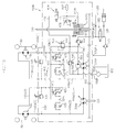
- Fig. 1 is an oil hydraulic circuit diagram of a working vehicle to which a pump unit according to a first embodiment of the present invention is applied.
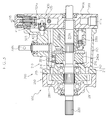
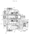
- Fig. 2 is a cross-sectional plan view of the pump unit of the first embodiment.
- Fig. 3 is a longitudinal cross-sectional side view of the pump unit taken along a line III-III in Fig. 2.
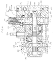
- Fig. 4 is a longitudinal cross-sectional side view of the pump unit taken along a line IV-IV in Fig. 2.
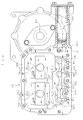
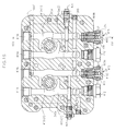
- Fig. 5 is a cross-sectional view taken along a line V-V in Fig. 2.
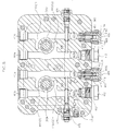
- Fig. 6 is a cross-sectional view taken along a line VI-VI in Fig. 2.
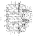
- Fig. 7 is a cross-sectional view taken along a line VII-VII in Fig. 2.
- Fig. 8 is a cross-sectional view taken along a line VIII-VIII in Fig. 2.
- Fig. 9 is a cross-sectional view of a port block in a modified pump unit of the present invention.
- Fig. 10 is a cross-sectional view of an auxiliary pump case, taken along a line X-X in Fig. 2.
- Fig. 11 is a cross-sectional view taken along a line XI-XI in Fig. 10.
- Fig. 12 is a cross-sectional view taken along a line XII-XII in Fig. 10.
- Fig. 13 is a cross-sectional view of a modified pump unit of the present invention.
- Fig. 14 is a cross-sectional view of a port block in a modified pump unit of the present invention.
- Fig. 15 is a hydraulic circuit diagram of a vehicle to which a pump unit according to a second embodiment of the present invention.
- Fig. 16 is a longitudinal cross-sectional front view of a port block in the pump unit of the second embodiment.
- Fig. 17 is a cross sectional view taken along a line XVII-XVII in Fig. 16.
- Fig. 18 is a longitudinal cross-sectional view of a port block in a modified pump unit of the present invention.
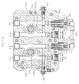
- Fig. 19 is a longitudinal cross-sectional view of a port block in another modified pump unit of the present invention.
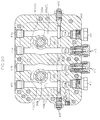
- Fig. 20 is a longitudinal cross-sectional view of a port block in still another modified pump unit of the present invention.
- Hereinafter, a preferred embodiment of a pump unit according to the present invention will be described with reference to the attached drawings.
- Fig. 1 illustrates an oil hydraulic circuit diagram of a working
vehicle 1 to which a pump unit according to this embodiment is applied. Fig. 2 illustrates a cross-sectional plan view of thepump unit 100 according to this embodiment. Fig. 3 and Fig. 4 are longitudinal cross-sectional side views of thepump unit 100 taken along a line III-III and a line IV-IV in Fig. 2, respectively. - The
pump unit 100 according to this embodiment is configured to form a main transmission path for transmitting the rotational power from a driving power source (not shown) to an actuator through a pair ofhydraulic fluid lines - More specifically, as illustrated in Fig. 1 to Fig. 4, the
pump unit 100 includes aninput shaft 220 which is operatively connected to the driving power source, hydraulic pumpmain bodies input shaft 220 and are fluidly connected to the aforementioned actuator through the pair ofhydraulic fluid lines PTO shaft 610 which is operatively driven by theinput shaft 220, and a PTOclutch mechanism 600A inserted in the transmission path from theinput shaft 200 to thePTO shaft 610, wherein the hydraulic pumpmain bodies PTO shaft 610 and the PTOclutch mechanism 600A form a part of the secondary transmission path. - Further, the
pump unit 100 according to this embodiment includes aPTO braking mechanism 600B which operates in conjunction with the PTOclutch mechanism 600A. ThePTO braking mechanism 600B is provided in order to prevent thePTO shaft 610 from being continuously rotated due to an inertial force when the power to thePTO shaft 610 from theinput shaft 220 is shutoff. - In this embodiment, the
pump unit 100 includes a pair of first and second hydraulic pumpmain bodies - The pair of first and second hydraulic pump
main bodies hydraulic motor units hydraulic fluid lines main body 300a and the firsthydraulic motor unit 10a form a first HST for vehicle-traveling which drives one of a pair of drivingwheels 50 with variable rotational speeds. The second hydraulic pumpmain body 300b and the secondhydraulic motor unit 10b form a second HST for vehicle-traveling which drives the other one of the pair of drivingwheels 50 with variable rotational speeds. - Namely, out of the first hydraulic pump
main body 300a and the motor main body in the firsthydraulic motor unit 10a, at least one of them is of a variable displacement type. - Similarly, out of the second hydraulic pump
main body 300b and the motor main body in the secondhydraulic motor unit 10b, at least one of them is of a variable displacement type. - In this embodiment, the first and second hydraulic pump
main bodies hydraulic motor units - More specifically, the
pump unit 100 includes ahousing 200 which supports theinput shaft 220 and thePTO shaft 610 and accommodates the first and second hydraulic pumpmain bodies clutch mechanism 600A, and atransmission mechanism 280 which transmits the power from theinput shaft 220 to the first hydraulic pumpmain body 300a, the second hydraulic pumpmain body 300b and the PTOclutch mechanism 600A and also is accommodated within thehousing 200, in addition to theinput shaft 200, the first and second hydraulic pumpmain bodies PTO shaft 610 and the PTOclutch mechanism 600A. - Fig. 5 to Fig. 8 illustrate cross-sectional views taken along a line V-V, a line VI-VI, a line VII-VII and a line VIII-VIII in Fig. 2, respectively.
- As illustrated in Fig. 2 and Fig. 5 to Fig. 7, the
housing 200 includes a housingmain body 210 which accommodates the first and second hydraulic pumpmain bodies clutch mechanism 600A, a center section (port block) 360 which is detachably connected to the housingmain body 210 and is provided with fluid passages fluidly communicated with the first and second hydraulic pumpmain bodies cover member 250 which is detachably connected to the housingmain body 210 at the opposite side from theport block 360 in the direction of the rotation axes of the hydraulic pumpmain bodies - In this embodiment, the first and second hydraulic pump
main bodies housing 200 such that the directions of their rotation axes are in parallel with each other along the fore-to-aft direction of the vehicle. Further, thePTO shaft 610 is also supported by thehousing 200 such that the rotation axis thereof is in parallel with the direction of the rotation axes of the first and second hydraulic pumpmain bodies - More specifically, as illustrated in Fig. 2, the housing
main body 210 includes a first end-face portion 211 positioned at one side in the direction of the rotation axes of the first and second hydraulic pumpmain bodies face portion 212 spaced apart from the first end-face portion 211 at the other side in the direction of the rotation axes, and awall portion 213 extending along the direction of the rotation axes between the first end-face portion 211 and the second end-face portion 212. - The first end-
face portion 211 includes afirst opening 211 a which allows the first and second hydraulic pumpmain bodies main body 210. - Further, the
first opening 211a is liquid-tightly sealed with theport block 360. - Namely, the
housing 200 is configured to define a pumpaccommodating space 201 for accommodating the first and second hydraulic pumpmain bodies port block 360 and the second end-face portion 212 (see Fig. 2). - The second end-
face portion 212 includes a swashplate receiving portion 212a having a concave arc-shaped guiding surface for slidably abutting and supporting a movable swash plate 353 which will be described later of the first and second hydraulic pumpmain bodies accommodating space 201, and asecond opening 212b which allows the PTOclutch mechanism 600A to pass therethrough at the other side of thehousing 200 in the vehicle-widthwise direction (see Fig. 2). - Further, the
second opening 212b is liquid-tightly sealed with thecover member 250. - Namely, the
housing 200 is configured to define a PTO clutchaccommodating space 202 for accommodating the PTOclutch mechanism 600A between thecover member 250 and the first end-face portion 211. - As described above, in this embodiment, the internal space of the
housing 200, which is defined by theport block 360 and the second end-face portion 212, at one side in the widthwise direction is utilized as the pumpaccommodating space 201 while the internal space of thehousing 200, which is defined by thecover member 250 and the first end-face portion 211, at the other side in the widthwise direction is utilized as the PTO clutchaccommodating space 202. - Further, in this embodiment, the swash
plate receiving portion 212a is formed integrally with the housingmain body 210 and, accordingly, thefirst opening 211a which allows the first and second hydraulic pumpmain bodies second opening 212b which allows the PTOclutch mechanism 600A to pass therethrough are provided at one side and the other side in the direction of the rotation axes of the first and second hydraulic pumpmain bodies plate receiving portion 212a may be formed separately from the housingmain body 210. - By forming the swash
plate receiving portion 212a separately from the housingmain body 210, it is possible to eliminate the necessity of the second end-face portion 212. Consequently, when molding the housingmain body 210, it is possible to pull out the respective molds for forming the hydraulicpump housing portion 201 and the PTOclutch housing portion 202 in the same direction. - The
cover member 250 is detachably connected to the housingmain body 210 so as to form a transmission mechanism accommodating space 203 (see Fig. 2) for accommodating thetransmission mechanism 280 between thecover member 250 and the second end-face portion 212 of the housingmain body 210. - Further, as illustrated in Fig. 3, the second end-
face portion 212 may be provided with acommunication channel 215 which allows fluid to freely flow between the hydraulic pumpaccommodating space 201 and the transmission mechanismaccommodating space 203. - As illustrated in Fig. 2 and Fig. 3, the
input shaft 220 is supported by thehousing 200 in a state where its first end at the upstream side in the direction of transmission is outwardly extended from thehousing 200 so as to be operatively connected to the driving power source. - In this embodiment, the
input shaft 200 is formed integrally with afirst pump shaft 310a of the first hydraulic pumpmain body 300a. - In this embodiment, the first hydraulic pump
main body 300a is of an axial piston type as illustrated in Fig. 2 and Fig. 3. - More specifically, the first hydraulic pump
main body 300a includes thefirst pump shaft 310a which is operatively connected to theinput shaft 220, afirst cylinder block 320a supported on thefirst pump shaft 310a in a relatively non-rotatable manner, and afirst piston unit 330a accommodated within thecylinder block 320a in a relatively non-rotatable manner and a relatively axially slidable manner. - As previously described, in this embodiment, the first hydraulic pump
main body 300a is of a variable displacement type. - Consequently, in addition to the aforementioned structures, the first hydraulic pump
main body 300a includes an output-adjustingmember 340a for changing the range of sliding of thepiston unit 330a to adjust the suction/discharge rate. - In this embodiment, a cradle-type movable swash plate is employed as the output-adjusting
member 340a. - More specifically, the
movable swash plate 340a has a convex arc-shaped rear surface which is in intimate contact with a thrust metal secured on the concave arc-shaped surface of the swashplate receiving portion 212a so that themovable swash plate 340a is slidably supported, and a front surface which is abutted against a shoe provided at the tip end of thepiston unit 330a. Further, there is provided a thrustmetal engaging protrusion 216 for preventing the inclination of the thrust metal, at the deepest portion of the concave arc-shaped surface of the swashplate receiving portion 212a (see Fig. 3). - Further, the output-adjusting
member 340a can be manipulated from outside using acontrol shaft 350a which is connected thereto through an arm 351a (see Fig. 3). - As previously described, in this embodiment, a first side of the
first pump shaft 310a is formed integrally with theinput shaft 220 which is outwardly extended. - Further, as illustrated in Fig. 2 and Fig. 3, a second side of the
first pump shaft 310a is supported by theport block 360, the second end-face portion 212 and thecover member 250 in a relatively rotatable manner about its axis, at a state where the second side at the downstream-side end portion in the direction of transmission is outwardly extended through theport block 360. - In this embodiment, a cooling
fan 800 is provided on the second side of thefirst pump shaft 310a (see Fig. 2). - Obviously, the outwardly extended portion of the
first pump shaft 310a at the second side may be used as theinput shaft 220. Further, asecond pump shaft 310b, which will be described later, may be configured to have an outwardly extended portion beyond anauxiliary pump case 520, and then the coolingfan 800 may be provided on the outwardly extended portion of thesecond pump shaft 310b. - The second hydraulic
pump maim body 300b has substantially the same structure as that of the first hydraulicpump maim body 300a. - Consequently, detailed description of the second hydraulic
pump maim body 300b will be properly omitted by replacing the end reference character "a" of the first hydraulicpump maim body 300a with "b". - The
second pump shaft 310b is supported in a relatively rotatable manner about its axis by theport block 360, the second end-face portion 212 and thecover member 250 at a state where a downstream-side end portion in the direction of transmission is extended outwardly through theport block 360. - Further, an auxiliary pump
main body 510, which will be described later, is supported on the outwardly extended portion of thesecond pump shaft 310b. - As illustrated in Fig. 2, the
PTO shaft 610 is supported in a relatively rotatable manner about its axis by the first end-face portion 211 and thecover member 250 at a state where the downstream-side end portion in the direction of transmission is extended outwardly at the opposite side from the upstream-side of theinput shaft 220. - The PTO
clutch mechanism 600A includes a driving-side member 620 which is supported on thePTO shaft 610 in a relatively rotatable manner and is operatively connected to theinput shaft 220, a driven-side member 630 which is supported on thePTO shaft 610 in a relatively non-rotatable manner, andfriction plate unit 640 including driving-side friction plates supported by the driving-side member 620 in a relatively non-rotatable manner and driven-side friction plates supported by the driven-side member 630 in a relatively non-rotatable manner, wherein thefriction plate unit 640 can be selectively engaged or disengaged with the effect of the hydraulic pressure to engage or disengage the power transmission from theinput shaft 220 to thePTO shaft 610. - The
transmission mechanism 280 is configured to be capable of transferring the rotational power of theinput shaft 220 to thefirst pump shaft 310a, thesecond pump shaft 310b and the driving-side member 620, as illustrated in Fig. 2 and Fig. 4. - In this embodiment, the
transmission mechanism 280 includes afirst gear 281 supported on theinput shaft 220 in a relatively non-rotatable manner, asecond gear 282 supported on thesecond pump shaft 310b in a relatively non-rotatable manner with engaged with thefirst gear 281, and athird gear 283 provided on the driving-side member 620 such that it is engaged with thesecond gear 282. - As illustrated in Fig. 1, Fig. 2 and Fig. 4, the
pump unit 100 includes, in addition to the aforementioned structures, the auxiliary pumpmain body 510 which is operatively driven by theinput shaft 220, and anauxiliary pump case 520 connected to the outer surface of theport block 360 such that it surrounds the auxiliary pumpmain body 510. - In this embodiment, the auxiliary pump
main body 510 is driven by the outwardly extended portion of thesecond pump shaft 310b, as previously described. - The
pump unit 100 is configured to be capable of supplying fluid discharged from the auxiliary pumpmain body 510 to the pair of firsthydraulic fluid lines 400a and the pair of secondhydraulic fluid lines 400b as charge fluid, and also capable of supplying the discharged fluid to the PTOclutch mechanism 600A as operation fluid. - More specifically, as illustrated in Fig. 1, the
pump unit 100 includes asuction line 550 which has a first end fluidly connected to a fluid reservoir (the internal space of thehousing 200 in this embodiment) and a second end fluidly connected to a suction port of the auxiliary pumpmain body 510, adischarge line 560 which is fluidly connected to the discharge port of the auxiliary pumpmain body 510, acharge line 420 which supplies a part of the hydraulic fluid from thedischarge line 560 to the pair of the firsthydraulic fluid lines 400a and the pair of secondhydraulic fluid lines 400b through acheck valve 425, a PTOhydraulic fluid line 470 which supplies a part of the hydraulic fluid from thedischarge line 560 to the PTOclutch mechanism 600A through aPTO relief valve 478, a pressure-reducingvalve 530 which has a primary side fluidly connected to thedischarge line 560, and aresistance valve 540 which is fluidly connected to the primary side of the pressure-reducingvalve 530. - Further, the PTO
hydraulic fluid line 470 and thecharge line 420 are fluidly connected to the primary side and a secondary side of the pressure-reducingvalve 530, respectively, to enable maintaining the hydraulic pressure in thecharge line 420 constant regardless of whether or not the PTOclutch mechanism 600A is engaged or disengaged, thus preventing the malfunction of fluctuations in the operation torques of the output-adjustingmembers main bodies clutch mechanism 600A, which has been conventionally occurred. - Namely, in a conventional pump unit, the charge line and the PTO hydraulic fluid line are fluidly connected to the secondary side and the spring chamber of the pressure-reducing valve, respectively. This configuration induces the malfunction of a hydraulic pressure difference in the charge line between when the PTO clutch mechanism is engaged and when it is disengaged.
- More specifically, when the PTO clutch mechanism is engaged, the PTO hydraulic fluid line is maintained at a predetermined hydraulic pressure defined by a PTO relief valve which is inserted into the PTO hydraulic fluid line, while when the PTO clutch mechanism is disengaged, the PTO hydraulic fluid line is at a natural pressure since it is drained to the fluid reservoir.
- Consequently, in a conventional pump unit, when the PTO clutch mechanism is disengaged, the charge line is maintained at a predetermined hydraulic pressure with a hydraulic pressure setting spring of the pressure-reducing valve, while when the PTO clutch mechanism is engaged, the charge line is maintained at a pressure which is equal to the biasing force of the hydraulic pressure setting spring of the pressure-reducing valve plus the hydraulic pressure set by the PTO relief valve, since the hydraulic pressure of the PTO relief valve acts on the spring chamber of the pressure-reducing valve.
- Such hydraulic pressure fluctuations in the charge line induce back pressures acting on the
first piston unit 330a, thus causing fluctuations in the operation torques of the output-adjusting members in the hydraulic pump main bodies. Particularly, when the PTO clutch mechanism is engaged, the hydraulic pressure in the charge line rises, which causes an increase of the hydraulic pressure in the pair of hydraulic fluid lines, thus increasing the operation torques of the output-adjusting members. This offers discomfort to the operator and, for example, in a case where there is provided a neutral position returning mechanism for automatically returning the output-adjusting member to a neutral position in association with the release of the operating force, the returning to the neutral position will require a time or will not be completely attained in some cases due to the increase of the operation torque. - On the contrary, in this embodiment, as previously described, the
charge line 420 is fluidly connected to the secondary side of the pressure-reducingvalve 530 and the PTOhydraulic fluid line 470 is fluidly connected to the primary side of the pressure-reducingvalve 530. - Consequently, even in the event of fluctuations in the hydraulic pressure in the PTO
hydraulic fluid line 470 in association with the change of the state of the PTOclutch mechanism 600A, thecharge line 420 is maintained at a predetermined hydraulic pressure defined by the hydraulic pressure setting spring of the pressure-reducingvalve 530. Therefore, regardless of whether or not the PTOclutch mechanism 600A is actuated, the operation torques of the output-adjustingmembers main bodies - Further, in this embodiment, as illustrated in Fig. 1, the PTO
hydraulic fluid line 470 is fluidly connected to the primary side of the pressure-reducingvalve 530 through anorifice 472, and also surplus fluid in thedischarge line 560 is discharged to the outside of the system through theresistance valve 540. - Preferably, there may be provided a
drain line 570 for fluidly communicating the secondary side of theresistance valve 540 to the fluid reservoir, and anoil cooler 575 may be inserted in the drain line 570 (see Fig. 1). - By providing these structures, it is possible to effectively prevent the temperature rise in stored fluid in the fluid reservoir.
- More preferably, there may be provided an external hydraulic
fluid extraction line 580 for extracting hydraulic fluid from thedrain line 570 to outside. The external hydraulicfluid extraction line 580 is connected to, for example, a hydraulic actuator for lifting and lowering, with respect to the ground surface, a ground working machine (for example, a grass cutting mower machine) which is mounted on the workingvehicle 1 and driven by thePTO shaft 610. - In this embodiment, the
pump unit 100 includes the external hydraulicfluid extraction line 580 which has a first end fluidly connected to thedrain line 570, an outside hydraulicfluid return line 581 which has a first end fluidly connected to thedrain line 570, and a switchingvalve 582 for actuating the hydraulic actuator, the switchingvalve 582 being inserted in thedrain line 570 between the connectingpoint 580T of the external hydraulicfluid extraction line 580 and thedrain line 570 and the connectingpoint 581T of the outside hydraulicfluid return line 581 and thedrain line 570. - Further, the outside hydraulic
fluid return line 581 is connected to thedrain line 570 at the upstream side of theoil cooler 575, thus enabling effectively preventing the temperature rise in the fluid in the fluid reservoir. - In this embodiment, the
pump unit 100 includes an external hydraulicpressure relief valve 595 which has a primary side fluidly connected to thedischarge line 560, the external hydraulicpressure relief valve 595 being for setting the hydraulic pressure in the external hydraulicfluid extraction line 580. - Preferably, as illustrated in Fig. 1, there may be provided a
return line 590 which has a first end fluidly connected to thedischarge line 560 and a second end fluidly connected to thesuction line 550, and the external hydraulicpressure relief valve 595 may be inserted in thisreturn line 590. - The concrete structures of the aforementioned respective hydraulic pressure lines will be described.
- As illustrated in Fig. 8, in the
port block 360, there are formed a pair of firsthydraulic fluid passages 410a forming a part of the pair of firsthydraulic fluid lines 400a and a pair of second hydraulicfluid passages 410b forming a part of the pair of secondhydraulic fluid lines 400b. - The pair of the first
hydraulic fluid passages 410a and the pair of second hydraulicfluid passages 410b have substantially the same structure. Consequently, detailed description of the pair of the second hydraulicfluid passages 410b will be properly omitted by replacing the end reference character "a" of the pair of the firsthydraulic fluid passages 410a with "b". - Each of the pair of the first
hydraulic fluid passages 410a includes a kidney port serving as a fluid communication port to the corresponding first hydraulic pumpmain body 300a and ahydraulic fluid port 411a which is opened into the outer surface to serve as a fluid communication port to the firsthydraulic motor unit 10a. - In this embodiment, as illustrated in Fig. 8, the pair of first
hydraulic fluid passages 410a are formed in the port block such 360 that their first ends and second ends are opened to the outer surface, wherein the first ends form thehydraulic fluid ports 411a and the middle portions form the kidney ports. - Out of the pair of the first
hydraulic fluid passages 410a, the forward-movement low-pressure side firsthydraulic fluid passage 410a(2), which is brought into a low pressure during forward movement of the vehicle, is so configured that the second end is closed by aplug 412. On the other hand, the forward-movement high-pressure side firsthydraulic fluid passage 410a(1), which is brought into a high pressure during forward movement of the vehicle, is so configured that the second end is sealed with arelief valve 415 which will be described later. - Specifically, out of the pair of first
hydraulic fluid passages 410a and the pair of second hydraulicfluid passages 410b, the forward-movement high-pressure side firsthydraulic fluid passage 410a(1) and the forward-movement high-pressure side secondhydraulic fluid passage 410b(1), which are in high pressure state during forward movement, are provided with a relief mechanism which releases the hydraulic pressures in the forward-movement high-pressure side firsthydraulic fluid passage 410a(1) and the forward-movement high-pressure side secondhydraulic fluid passage 410b(1) to the forward-movement low-pressure side firsthydraulic fluid passage 410a(2) and the forward-movement low-pressure side secondhydraulic fluid passage 410b(2), respectively, when the hydraulic pressures in the forward-movement high-pressure side firsthydraulic fluid passage 410a(1) and the forward-movement high-pressure side secondhydraulic fluid passage 410b(1) exceed a predetermined hydraulic pressure. - In this embodiment, as illustrated in Fig. 4 and Fig. 8, the relief mechanism includes
relief fluid passages 413 formed in theport block 360 so as to have first ends fluidly communicated with the second end of the forward-movement high-pressure sidehydraulic fluid passage 410a(1) and 410b(1) and second ends opened into the surface abutting the housingmain body 210, and therelief valves 415 mounted in theport block 360 so as to be positioned between the forward-movement high-pressure sidehydraulic fluid passage 410a(1) and 410b(1) and the correspondingrelief fluid passages 413. - Further, in this embodiment, in order to enable easily coping with specification changes, there are further formed, in the
port block 360,relief fluid passages 413 corresponding to the forward-movement low-pressure hydraulicfluid passages 410a(2) and 410b(2). Theplugs 412 are adapted to intercept between therelief fluid passages 413 and the corresponding forward-movement low-pressure side hydraulicfluid passages 410a(1) and 410b(2). - As illustrated in Fig. 8, the
relief valves 415 include avalve housing 416 including a valve case having an opening communicated to the forward-movement high-pressure sidehydraulic fluid passage 410a(1) or 410b(1) and a cap which is detachably mounted on the valve case, a valvemain body 417 which is slidably accommodated within thevalve housing 416, the valvemain body 417 being capable of being positioned at a shutting-off position for closing the opening and a communicating position for causing the opening to be opened, and arelief spring 418 for biasing the valvemain body 417 towards the shutting-off position. - The
relief valves 415 act as follows. When the hydraulic pressures in the forward-movement high-pressure side hydraulicfluid passages 410a(1) and 410b(1) are equal to or less than a predetermined hydraulic pressure defined by the biasing force of the relief springs 418, therelief valves 415 intercept between the forward-movement high-pressure side hydraulicfluid passages 410a(1) and 410b(1) and therelief fluid passages 413. Also, when the hydraulic pressures in the forward-movement high-pressure side hydraulicfluid passages 410a(1) and 410b(1) exceed the predetermined hydraulic pressure, therelief valves 415 cause the forward-movement high-pressure side 410a(1) and 410b(1) to be communicated with therelief fluid passages 413. Consequently, in the event that thehydraulic motor units fluid passages 410a(1) and 410b(1) to protect the first and second hydraulic pumpmain bodies - More specifically, as illustrated in Fig. 8, the
valve housing 416 may be provided with apressure maintaining chamber 416C which slidably supports the base end portion of the valvemain body 417, thepressure maintaining chamber 416C being separated from therelief fluid passage 413. Further, the valvemain body 417 may be provided with anaxial hole 417H between the tip end portion and the base end portion thereof, theaxial hole 417H having an orifice. - By providing these structures, it is possible to slow the movement of the valve
main body 417 from the shutting-off position to the communicating position and the movement thereof from the communicating position to the shutting-off position, thereby effectively preventing damping and/or chattering. Further, while in this embodiment therelief valves 415 are inserted only between the forward-movement high-pressure side hydraulicfluid passages 410a(1) and 410b(1) and the correspondingrelief fluid passages 413, and theplugs 412 are employed to intercept between the forward-movement low-pressure side hydraulicfluid passages 410a(2) and 410b(2) and the correspondingrelief fluid passages 413 as previously described, it is possible to mount therelief valves 415 between the forward-movement low-pressure side hydraulicfluid passages 410a(2) and 410b(2) and the correspondingrelief fluid passages 413. With the configuration, even in the event that the hydraulicpressure motor units fluid passages 410a(2) and 410b(2) to protect the first and second hydraulic pumpmain bodies - Further, while in this embodiment, the
relief valves 415 having thepressure maintaining chambers 416C are employed as previously described, it is possible to insert arelief valve 415B having no such apressure maintaining chamber 416C between the forward-movement high-pressure sidehydraulic fluid passage 410a(1) and therelief fluid passage 413 as illustrated in Fig. 9. - This modified configuration illustrated in Fig. 9 can slow the movement of the valve
main body 417 between the shutting-off position and the communicating position, while reducing the manufacturing cost. - In the configuration illustrated in Fig. 9,
relief valves 415B' are further provided in the forward-movement low-pressure side hydraulicfluid passages 410a(2) and 410b(2). - The relief valve main bodies 417' of the
relief valves 415B' include noaxial hole 417H with an orifice. - Further, as illustrated in Fig. 8, there are formed, in the
port block 360, a pair of bypassfluid passages 430 for communicating the pair of firsthydraulic fluid passages 410a to each other and for communicating the pair of second hydraulicfluid passages 410b to each other. - Further, switching valves 436 for opening/ closing the pair of bypass
fluid passages 430 are mounted in theport block 360. - By providing these bypass
fluid passages 430 and the switchingvalves 435, it is possible to prevent the occurrence of hydraulic pressure differences between the pair of firsthydraulic fluid lines 400a and between the pair of secondhydraulic fluid lines 400b resulting in resistances, when the vehicle is forcibly towed. - Fig. 10 illustrates a cross-sectional view of the
auxiliary pump case 520 taken along a line X-X in Fig. 2. In Fig. 10, there are illustrated different cross sections. - Fig. 11 illustrates a cross-sectional view taken along a line XI-XI in Fig. 10.
- As illustrated in Fig. 1, Fig. 2 and Fig. 10, in the
auxiliary pump case 520, there is formed asuction fluid passage 551 which has a first end opened to the outer surface to form asuction port 550P and a second end fluidly connected to the suction port of the auxiliary pumpmain body 510. - The
suction port 550P is fluidly connected to anexternal tank 900, which is placed separately from the housing 300, through anexternal conduit 552 having afilter 553 inserted therein (see Fig. 1). - In this embodiment, the
external conduit 552 and thesuction fluid passage 551 form thesuction line 550. - The
external tank 900 is connected to the inside space of thehousing 200 such that fluid can be freely communicated therebetween via acommunication port 200P formed on thewall 213 of the housing 200 (see Fig. 1 and Fig. 6) and anexternal conduit 910 connected to thecommunication port 200P. Namely, in this embodiment, the inside space of thehousing 200 and theexternal tank 900 form the fluid reservoir. - Further, as illustrated in Fig. 1, Fig. 4 and Fig. 10, in the
auxiliary pump case 520, there are formed asuction fluid passage 561 which has a first end fluidly connected to the discharge port of the auxiliary pumpmain body 510 to form thedischarge line 560, a return fluid passage 591 (see Fig. 10) which has a first end fluidly connected to thedischarge fluid passage 561 and a second end fluidly connected to thesuction fluid passage 551, and the external hydraulic pressure relief valve 595 (see Fig. 10) inserted in thereturn fluid passage 591. - Further, as illustrated in Fig. 10, the
auxiliary pump case 520 incorporates the pressure-reducingvalve 530 such that the primary side thereof is fluidly connected to thedischarge fluid passage 561 and also incorporates theresistance valve 540 such that it is fluidly connected to the primary side of the pressure-reducingvalve 530. - Further, in the
auxiliary pump case 520, there is formed an auxiliary -pump-case side commoncharge fluid passage 521 which has a first end fluidly connected to the secondary side of the pressure-reducingvalve 530 and has a second end opened to the surface abutting theport block 360, wherein the secondary-pump-case side commoncharge fluid passage 521 forms a part of the charge line 520 (see Fig. 10 and Fig. 11). - More specifically, in this embodiment, the charge line 520 includes the auxiliary -pump-case side common charge fluid passage 521 formed in the auxiliary pump case 520 (see Fig. 10 and Fig. 11), a port block side charge fluid passage 522 which is formed in the port block 360 such that it has a first end fluidly connected to the auxiliary - pump-case side common charge fluid passage 521 and a second end opened to the surface abutting the first end-face portion 211 of the housing main body 210 (see Fig. 5, Fig. 8 and Fig. 11), a charge fluid groove 523 formed in the outer surface (the surface abutting the port block 360) of the first end-face portion 211 of the housing main body 210 such that it is fluidly connected to the port block side common charge fluid passage 522 (see Fig. 5 and Fig. 11), a pair of first charge fluid passages 524a formed in the port block 360 such that they have first ends fluidly connected to the charge fluid groove 523 and second ends fluidly connected to the pair of first hydraulic fluid passages 410a (see Fig. 5 and Fig. 8), a pair of second charge fluid passages 524b formed in the port block 360 such that they have first ends fluidly connected to the charge fluid groove 523 and second ends fluidly connected to the pair of second hydraulic fluid passages 410b (see Fig. 5 and Fig. 8), and check valves 425 inserted in the pair of first charge fluid passages 524a and the pair of second charge fluid passages 524b for allowing fluid to flow from the corresponding charge fluid passages 524a and 524b into the corresponding hydraulic fluid passages 410a and 410b and for preventing the reverse flow thereof (see Fig. 1 and Fig. 4).
- In this embodiment, between the forward-movement low-pressure side hydraulic
fluid passages 410a(2), 410b(2) and the chargefluid passages 524b, orifices are respectively provided in parallel with thecheck valve 425 to prevent the reduction of the transmission efficiently during forward movement, while increasing the neutral ranges of the first HST and the second HST (see Fig. 1). - These orifices may be provided either in the valve cases for the rearward-
side check valves 425 or in theplugs 412 as illustrated in Fig. 14. The latter configuration enables utilizing common valve cases for both the forward and rearward-side check valves 425 and also enables eliminating assembly errors. - Further, in this embodiment, the secomd end portions of the
relief fluid passages 413 are opened into the charge fluid groove 543 (see Fig. 4 and Fig. 5). - Namely, when the pressures in the forward-movement high-pressure side hydraulic
fluid passages 410a(1) and 410b(b) become abnormally high, the hydraulic fluid flows from the forward-movement high-pressure side hydraulicfluid passages 410a(1) and 410b(b) into the forward-movement low-pressure side hydraulicfluid passages 410a(2) and 410b(2) through therelief fluid passages 413, thecharge fluid groove 523 and the charge fluid passages 524. - Further, as illustrated in Fig. 1, in addition to the aforementioned hydraulic lines, the
pump unit 100 according to this embodiment includes a self-suction line 440 which has a first end fluidly connected to the aforementioned fluid reservoir (the internal space of the housing 200) and a second end fluidly connected to thecharge line 420, wherein there is inserted therein acheck valve 445 which allows fluid to flow from the fluid reservoir to thecharge line 420 while preventing the reverse flow thereof. - In the event that any one of the pair of first
hydraulic fluid lines 400a or any one of secondhydraulic fluid lines 400b is brought into a negative pressure during standstill of the auxiliary pumpmain body 510, the self-suction line 440 sucks fluid from the fluid reservoir into the hydraulic fluid line at such a negative pressure. - Namely, for example, when the working vehicle is parked at a slope or the like and the engine 40 is stopped with the HST being at a neutral state, a rotational force is applied to the motor shaft which is operatively connected to the driving wheel 40, thereby the
hydraulic motor units - At this time, when the pair of first
hydraulic fluid lines 400a and the pair of secondhydraulic fluid line 400b are filled with hydraulic fluid, braking forces are acted on thehydraulic motor units hydraulic fluid lines 400a and one of the pair of secondhydraulic fluid lines 400b are raised to a high pressure with the pumping action of thesehydraulic motor units - In the event of the occurrence of hydraulic fluid leakage, the fluid is circulated from the negative-pressure side hydraulic fluid line to the high-pressure side hydraulic fluid line, in the pair of first
hydraulic fluid lines 400a and the pair of secondhydraulic fluid lines 400b, thus facilitating hydraulic fluid leakage from the high-pressure side hydraulic fluid line. Finally, the hydraulic fluid is removed from the pair of firsthydraulic fluid lines 400a and the pair of secondhydraulic fluid lines 400b, which causes the driving wheels to freely rotate and thus causes the vehicle to start descending the slope (free wheel phenomenon). - In view of this point, the pump unit according to this embodiment includes the self-
suction line 440 so that, in the event that any one of the pair of firsthydraulic fluid lines 400a or any one of secondhydraulic fluid line 400b is brought into a negative-pressure, fluid is supplied from the fluid reservoir (the inside space of thehousing 200 in the illustrated embodiment) to the negative-pressure side hydraulic fluid line, thus effectively preventing the aforementioned free wheel phenomenon. - More specifically, as illustrated in Fig. 11, the self-
suction line 440 includes a first self-suction fluid passage 441 formed in theport block 360 such that it has a first end opened to the inside space of thehousing 200 and a second end opened to the surface abutting theauxiliary pump case 520, and a second self-suction fluid passage 442 formed in theauxiliary pump case 520 such that it has a first end opened to the surface abutting theport block 360 to be fluidly connected to the first self-suction fluid passage 441 and a second end communicated with the auxiliary -pump-case side commoncharge fluid passage 521. - Further, the
check valve 445 is mounted on theauxiliary pump case 520 so as to allow fluid to flow only in the direction from the first self-section fluid passage 441 to the second self-suction fluid passage 442 through the surface abutting (contacting) theport block 360. - Fig. 12 is a cross-sectional view taken along a line XII-XII in Fig. 10.
- Further, as illustrated in Fig. 4, Fig. 10 and Fig. 12, the
auxiliary pump case 520 is provided with a first PTO hydraulic fluid passage 47 1a which has a first end fluidly connected to the primary side of the pressure-reducingvalve 530 and a second end opened to the surface abutting theport block 360, anorifice 472 inserted in the first PTO hydraulic fluid path 471, a PTO hydraulicfluid groove 473 which is formed at the surface abutting theport block 360 so as to be fluidly connected to the first PTO hydraulic fluid passage, asolenoid valve 474, a second PTOhydraulic fluid passage 471b which has a first end fluidly connected to the PTO hydraulicfluid groove 473 and a second end fluidly connected to the primary side of thesolenoid valve 474, a third PTOhydraulic fluid passage 471c which has a first end fluidly connected to the secondary side of thesolenoid valve 474 and a second end opened to the surface abutting theport block 360 at a position spaced apart from the PTO hydraulicfluid groove 473, and a PTOdrain fluid passage 650a which has a first end fluidly connected to the drain port of thesolenoid valve 474 and a second end opened to the surface abutting theport block 360. - Further, the first PTO
hydraulic fluid passage 471a, thethrottle 472, the PTO hydraulicfluid groove 473, thesolenoid valve 474, the second PTOhydraulic fluid passage 471b and the third PTOhydraulic fluid passage 471c form a part of the PTO hydraulic fluid line 470 (see Fig. 1). - The PTO
drain fluid passage 650a is opened into the internal space of thehousing 200 via a PTOdrain fluid passage 650b formed in the port block 360 (see Fig. 12). - As illustrated in Fig. 7, Fig. 10 and Fig. 12, the PTO
hydraulic fluid line 470 further includes a fourth PTOhydraulic fluid passage 471d formed in theport block 360 such that it has a first end fluidly connected to the downstream end portion of the third PTOhydraulic fluid passage 471c and a second end opened to the surface abutting the first end-face portion 211 of the housingmain body 210, a fifth PTOhydraulic fluid passage 471e formed in the first end-face portion 211 such that it has a first end fluidly connected to the fourth PTOhydraulic fluid passage 471d and a second end opened to the internal space of thehousing 200, and anaccumulator 660 incorporated in the first end-face portion 211 such that it is inserted in the fifth PTOhydraulic fluid passage 471e, theaccumulator 660 including aninlet port 660a for fluidly connecting a hydraulic chamber of theaccumulator 660 to the fifth PTOhydraulic fluid passage 471 e. Further, the PTOhydraulic fluid line 470 includes a PTOinternal conduit 475 provided within the internal space of thehousing 200 such that it has a first end fluidly connected to the downstream end portion of the fifth PTOhydraulic fluid passage 471e and a second portion reaching the inner surface of thecover member 250, a sixth PTOhydraulic fluid passage 471f formed in thecover member 250 such that it has a first end fluidly connected to the downstream end portion of the PTOinternal conduit 475 and a second end opened to an inner surface of a bearing hole which supports thePTO shaft 610 in a bearing manner, and a seventh PTOhydraulic fluid passage 471g formed in thePTO shaft 610 such that it has a first end opened to the outer surface within the bearing hole and a second end opened to the PTOclutch mechanism 600A. Further, the PTOhydraulic fluid line 470 includes a rotary joint 476 formed between the inner surface of the bearing hole and the outer surface of thePTO shaft 610 such that it fluidly connects the sixth PTOhydraulic fluid passage 471 f to the seventh PTO hydraulic fluid passage 47 1f, a PTOrelief fluid passage 477 formed in thecover member 250 such that it has a first end fluidly connected to the rotary joint 476 and a second end opened to the internal space of thehousing 200, and thePTO relief valve 478 inserted in the PTOrelief fluid passage 477. - As previously described, in the
pump unit 100 according to this embodiment, theaccumulator 660 for gradually raising the hydraulic pressure in the PTOhydraulic fluid line 470 to a predetermined hydraulic pressure defined by thePTO relief valve 478 is incorporated in thehousing 200 which accommodates the first hydraulic pumpmain body 300a, the second hydraulic pumpmain body 300b and the PTOclutch mechanism 600A. This facilitates the efficiency of the piping operation, the prevention of leakage of hydraulic fluid and the reduction of the size of the entire apparatus. - More specifically, as illustrated in Fig. 12, in this embodiment, the portion of the first end-
face portion 211 other then the portion for supporting the PTO shaft 610 (above the portion for supporting thePTO shaft 610, in this embodiment) is made to be a thick portion. - Further, as illustrated in Fig. 5 and Fig. 10, the
accumulator 660 is incorporated within the thick portion of the first end-face portion 211 such that its axis is substantially orthogonal to the rotation axes of the first and second hydraulic pumpmain bodies - Instead thereof, as illustrated in Fig. 13, the
accumulator 660 may be incorporated within thewall 213 of the housingmain body 210 such that its axis is substantially parallel to the rotation axes of the first and second hydraulic pumpmain bodies - Namely, in the embodiment illustrated in Fig. 13, the
accumulator 660 is incorporated within thewall 213, and there is formed afluid groove 665 which fluidly communicates the forth PTOhydraulic fluid passage 471d or the fifth PTOhydraulic fluid passage 471e to theinlet port 660a of theaccumulator 660, at the surface of the first end-face portion 211 abutting theport block 360. - This configuration facilitates the efficiency of the piping operation, the prevention of leakage of hydraulic fluid and the reduction of the size of the entire apparatus, similarly to this embodiment.
- Further, as illustrated in Fig. 4, Fig. 10 and Fig. 11, the
auxiliary pump case 520 is provided with theresistance valve 540 which is fluidly connected to the primary side of the pressure-reducingvalve 530, adrain fluid passage 571 which has a first end fluidly connected to the secondary side of theresistance valve 540 and has a second end opened to the outer surface to form an outlet port 570Pout, and a firstreturn fluid passage 651 which has a first end fluidly connected to a spring chamber of theresistance valve 540 and a second end opened to the surface abutting theport block 360. - Further, as illustrated in Fig. 11, the first
return fluid passage 651 is opened into the fluid reservoir (the internal space of thehousing 200 in this embodiment) through a secondreturn fluid passage 652 formed in theport block 360. - The
drain fluid passage 571 forms a part of thedrain line 570. - More specifically, as illustrated in Fig. 1, in addition to the
drain fluid passage 571, thedrain line 570 includes a drainexternal conduit 572 which has a first end fluidly connected to thedrain fluid passage 571 via thedrain port 570P and a second end fluidly connected to the internal space of thehousing 200 via an inlet port 570Pin (see Fig. 2) formed in thewall 213 of the housingmain body 210. - In this embodiment, the external hydraulic
fluid extraction line 580 and the outside hydraulicfluid return line 581 are connected to the drainexternal conduit 572. - Further, the
oil cooler 575 is inserted in the drainexternal conduit 572. - Further, while in this embodiment there has been described the dual-type pump unit including the first and second hydraulic pump
main bodies housing 200, it is obvious that the present invention is not limited to this embodiment. - Namely, the present invention may be applied to a single-type pump unit including a single hydraulic pump main body within a housing and also may be applied to a hydrostatic transmission including a hydraulic pump main body and a hydraulic motor main body accommodated within a housing.
- Hereinafter, another preferred embodiment according to the present invention will be described with reference to the attached drawings.
- A
pump unit 100B according to this embodiment is applied to a vehicle such that it forms a part of the travel-system transmission path. The pump unit is configured to be capable of transmitting a rotational power from a driving power source that is operatively connected thereto to first and secondhydraulic motor units wheels 50 through a pair of firsthydraulic fluid lines 400a and a pair of secondhydraulic fluid lines 400b. - The components identical or corresponding to those in the aforementioned first embodiment will be designated by the identical reference characters and description thereof will be properly omitted.
- Fig. 15 illustrates a hydraulic circuit diagram of a vehicle to which the
pump unit 100B according to this embodiment is applied. - More specifically, the
pump unit 100B includes theinput shaft 220 which is operatively connected to the driving power source, the first and second hydraulic pumpmain bodies input shaft 220 and are fluidly connected to the first and secondhydraulic motor units hydraulic fluid lines 400a and the pair of secondhydraulic fluid lines 400b, a housing main body (not shown) accommodating the first and second hydraulic pumpmain bodies port block 360B (see Fig. 16) which abuts and supports the first and second hydraulic pumpmain bodies main bodies - More specifically, the first hydraulic pump
main body 300a forms a first HST in cooperation with the first hydraulic motor main body in the firsthydraulic motor unit 10a while the second hydraulic pumpmain body 300b forms a second HST in cooperation with the second hydraulic motor main body in the secondhydraulic motor unit 10b. - Namely, at least one of the first hydraulic pump
main body 300a and the first hydraulic motor main body is of a variable displacement type which varies the suction/discharge rate on the basis of the operation of the output-adjusting member. - Similarly, at least one of the second hydraulic pump
main body 300b and the second hydraulic motor main body is of a variable displacement type which varies the suction/discharge rate on the basis of the operation of the output-adjusting member. - Through the operation of the respective output-adjusting members in the first HST and the second HST, the left and right driving wheels can be individually driven in a variable-speed manner.
- As illustrated in Fig. 15, the
pump unit 100B further includes acommunication line 100 having anorifice 1100 inserted therein, thecommunication line 100 being for communicating the forward-movement high-pressure side firsthydraulic fluid line 400a(1) out of the pair of the firsthydraulic fluid lines 400a to the forward-movement high-pressure side secondhydraulic fluid line 400b(1) out of the pair of secondhydraulic fluid lines 400b, wherein the pressures in the forward-movement high-pressure side firsthydraulic fluid line 400a(1) and the forward-movement high-pressure side secondhydraulic fluid line 400b(1) are raised to higher pressures during forward movement. With this configuration, it is possible to effectively maintain the independent transmissions of the first and second HSTs while effectively preventing or reducing the occurrence of wandering phenomenon that the vehicle meanders even though the respective output-adjusting members of the first and second HSTs are operated such that the first and second HSTs are brought into the same output state. - Namely, by providing the
communication line 1000 with the orifice, it is possible to maintain the hydraulic pressure difference between the forward-movement high-pressure side firsthydraulic fluid line 400a(1) and the forward-movement high-pressure side secondhydraulic fluid line 400b(1) when the first and second HSTs are brought into different output states for rotating the vehicle, and also it is possible to prevent or reduce the occurrence of hydraulic pressure differences between the forward-movement high-pressure side firsthydraulic fluid line 400a(1) and the forward-movement high-pressure side secondhydraulic fluid line 400b(1) when the first and second HSTs are brought into the same output state for moving the vehicle straightly. - In this embodiment, the
communication line 1000 includes acommunication fluid passage 1010 formed in theport block 360B. - Fig. 16 illustrates a longitudinal cross-sectional front view of the
port block 360B. Further, Fig. 17 illustrates a cross sectional view taken along a line XVII-XVII in Fig. 16. - As illustrated in Fig. 16, the
port block 360B is provided with a pair of firsthydraulic fluid passages 410a forming a part of the pair of first hydraulic fluid lines and a pair of second hydraulicfluid passages 410b forming a part of the pair of secondhydraulic fluid lines 400b. - The pair of first
hydraulic fluid passages 410a and the pair of second hydraulicfluid passages 410b have substantially the same structure. Consequently, detailed description of the pair of second hydraulicfluid passages 410b will be properly omitted by replacing the end reference character "a" of the pair of firsthydraulic fluid passages 410a with "b". - Each of the pair of the first
hydraulic fluid passages 410a includes a kidney port forming a fluid communication port to the corresponding first hydraulic pumpmain body 300a and ahydraulic fluid port 411a which is opened to the outer surface to form a fluid communication port to the firsthydraulic motor unit 10a. - In this embodiment, as illustrated in Fig. 16, the pair of first
hydraulic fluid passages 410a are formed in theport block 360B so as to have first ends and second ends opened to the outer surface, wherein the first ends form thehydraulic fluid ports 411a and the middle portions form the kidney ports. - Out of the pair of the first
hydraulic fluid passages 410a, the forward-movement low-pressure side firsthydraulic fluid passage 410a(2) is so configured that aplug 412 closes the second end, the forward-movement high-pressure side firsthydraulic fluid passage 410a(1) is so configured that arelief valve 415 is mounted at the second end. - The
relief valve 415 is provided in order to flow the hydraulic fluid from the forward-movement high-pressure side firsthydraulic fluid passage 410a(1) to the forward-movement low-pressure side firsthydraulic fluid passage 410a(2), in the event that the hydraulic pressure in the forward-movement high-pressure side firsthydraulic fluid passage 410a(1) exceeds a predetermined hydraulic pressure, - The
relief valves 415 include a valvemain body 417 which receives the hydraulic pressures in the corresponding forward-movement high-pressure side hydraulicfluid passages 410a(1) and 410b(1), the valvemain body 417 having anaxial hole 417H with an orifice, and avalve housing 416 having apressure maintaining chamber 416C defined by the base end portion of the valvemain body 417, thepressure maintaining chamber 416C being separated from arelief fluid passage 413 which will be described later. - By providing these structures, it is possible to slow the movement of the valve
main bodies 417 with respect to the hydraulic pressure changes in the corresponding forward-movement high-pressure side hydraulicfluid passages 410a(1) and 410b(1), thus effectively preventing the occurrence of damping and/or chattering. - Further, the
port block 360B is provided with a pair of bypassfluid passages 430 for communicating the pair of firsthydraulic fluid passages 410a to each other and for communicating the pair of second hydraulicfluid passages 410b to each other, and a pair of switchingvalves 435 for opening/closing the pair of bypassfluid passages 430. - By providing these bypass
fluid passages 430 and the switchingvalves 435, it is possible to prevent the occurrence of hydraulic pressure differences between the pair of firsthydraulic fluid lines 400a and between the pair of secondhydraulic fluid lines 400b when the vehicle is forcibly towed in the event of engine failures and the like. - Further, as illustrated in Fig. 16 and Fig. 17, the
port block 360B is provided with a pair of firstcharge fluid passages 524a for supplying charge fluid from an auxiliary pumpmain body 510 provided in thepump unit 100B or a hydraulic fluid supplying apparatus such as the auxiliary pump unit placed separately from thepump unit 100B to the pair of firsthydraulic fluid passages 400a, a pair of secondcharge fluid passages 524b for supplying charge fluid from the auxiliary pump main body or the hydraulic fluid supplying apparatus to the pair of second hydraulicfluid passages 400b, and check valves 425 (see Fig. 15) inserted in the pair of firstcharge fluid passages 524a and the pair of secondcharge fluid passages 524b. - The
reference character 523 in Fig. 17 designates a charge fluid groove for supplying charge fluid from the auxiliary pump main body or the hydraulic fluid supplying apparatus to the pair of firstcharge fluid passages 524a and the pair of secondcharge fluid passages 524b. - The
reference character 413 in Fig. 16 and Fig. 17 designates a relief fluid passage for communicating the secondary sides of therelief valves 415 to thecharge fluid groove 523. - Further, as illustrated in Fig. 16, the
communication fluid passage 1010 is formed in theport block 360B such that it communicates the forward-movement high-pressure side firsthydraulic fluid passage 410a(1) and the forward-movement high-pressure side secondhydraulic fluid passage 410b(1) to each other. - More specifically, in this embodiment, the pair of first
hydraulic fluid passages 410a and the pair of second hydraulicfluid passages 410b are formed to be substantially parallel to each other at substantially the same position in the thicknesswise direction of theport block 360B. - As illustrated in Fig. 15 and Fig. 16, the
communication fluid passage 1010 is extended substantially in the direction orthogonal to the pair of firsthydraulic fluid passages 410a and the pair of second hydraulicfluid passages 410b at a position displaced from the pair of firsthydraulic fluid passages 410a and the pair of second hydraulicfluid passages 411 b in the thicknesswise direction of theport block 360B, such that it communicates only the forward-movement high-pressure side firsthydraulic fluid passage 410a and the forward-movement high-pressure side secondhydraulic fluid passage 410b(1) to each other. - While in this embodiment the
communication fluid passage 1010 is formed at the same side as the bypassfluid passages 430 with respect to the first andsecond pump shafts fluid passages 430 with respect to the first andsecond pump shafts - The communication fluid passage 1010' is provided with throttles at the positions communicated to both the forward-movement high-pressure side first
hydraulic fluid passage 410a(1) and the forward-movement high-pressure side secondhydraulic fluid passage 410b(1). - While in this embodiment the
communication line 1000 is formed by the communication fluid passage 1010 (or 1010') formed in theport block 360B, the present invention is not limited to this configuration. - For example, as illustrated in Fig. 18, the forward-movement high-pressure side first
hydraulic fluid passage 410a(1) and the forward-movement high-pressure side secondhydraulic fluid passage 410b(1) may be communicated to each other through anexternal communication conduit 1020 connected to theport block 360. - More specifically, in the configuration illustrated in Fig. 18, the
external communication conduit 1020 is configured to communicate thepressure maintaining chamber 416C of therelief valve 415 corresponding to the forward-movement high-pressure side firsthydraulic fluid passage 410a(1) with thepressure maintaining chamber 416C of therelief valve 415 corresponding to the forward-movement high-pressure side secondhydraulic fluid passage 410b(1). - With this configuration, it is possible to reduce the thickness of the
port block 360 in comparison with the configuration illustrated in Fig. 16 and Fig. 17, and also it is possible to utilize the damping-chattering preventing orifices provided in theaxial holes 417H in the relief valvemain bodies 417 as theorifices 1100 inserted in thecommunication line 1000. - Also, in the configuration in which the
communication line 1000 is formed by theexternal communication conduit 1020, it is possible to provide an orifice between theexternal communication conduit 1020, and at least one of thepressure maintaining chamber 416C in therelief valve 415 provided in the forward-movement high-pressure side firsthydraulic fluid passage 410a(1) and thepressure maintaining chamber 416C in therelief valve 415 provided in the forward-movement high-pressure side secondhydraulic fluid passage 410b(1), instead of the orifice provided in theaxial hole 417H, as illustrated in Fig. 19. - Further, in the configurations illustrated in Fig. 16, Fig. 18 and Fig. 19, the pair of first
hydraulic fluid passages 410a and the pair of second hydraulicfluid passages 410b are respectively concentrated at one side and the other side when viewed along the axes of thepump shafts - Specifically, in the aspects illustrated in Fig. 16, Fig. 18 and Fig. 19, between the forward-movement high-pressure side first
hydraulic fluid passage 410a(1) and the forward-movement high-pressure side secondhydraulic fluid passage 410b(1), there is placed one of the forward-movement low-pressure side hydraulic fluid passages (the forward-movement low-pressure side firsthydraulic fluid passage 410a(2) in the illustrated aspect). - Alternatively, as illustrated in Fig. 20, a
port block 360C can be formed such that the forward-movement high-pressure side firsthydraulic fluid passage 410a(1) is adjacent to the forward-movement high-pressure side secondhydraulic fluid passage 410b(1). This enables easily forming thecommunication line 1000 by utilizing holes forming one or both of the pair of bypassfluid passages 430. - Namely, the forward-movement high-pressure side first
hydraulic fluid passage 410a(1) and the forward-movement high-pressure side secondhydraulic fluid passage 410b(1) may be placed adjacent to each other at the center portion of theport block 360C, while the forward-movement low-pressure side firsthydraulic fluid passage 410a(2) and the forward-movement low-pressure side secondhydraulic fluid passage 410b(2) may be placed at outer positions of theport block 360C. Further, one or both of the pair of bypassfluid passages 430 may be extended at their inner end portions and theextended fluid passages 1030 may be used to form thecommunication line 1000 for communicating the forward-movement high-pressure side firsthydraulic fluid passage 410a(1) to the forward-movement high-pressure side secondhydraulic fluid passage 410b(1). - In the aspect illustrated in Fig. 19, the pair of bypass
fluid passages 430 are placed coaxially and both of the pair of bypassfluid passages 430 are extended at their inner end portions, wherein the orifice is formed between the opposite end portions of the pair of extendedfluid passages 1030. - This specification is by no means intended to restrict the present invention to the preferred embodiments set forth therein. Various modifications to the pump unit, as well as the hydrostatic transmission as described herein, may be made by those skilled in the art without departing from the spirit and scope of the present invention as defined in the appended claims.
Claims (23)
- A pump unit configured to be capable of transmitting a rotational power from a driving power source which is operatively connected thereto to an actuator through a pair of hydraulic fluid lines, the pump unit comprising:an input shaft which is operatively connected to the driving power source;a hydraulic pump main body which is operatively driven by the input shaft and is fluidly connected to the actuator through the pair of hydraulic fluid lines;a PTO shaft which is operatively driven by the input shaft;a PTO clutch mechanism which is inserted in a transmission path from the input shaft to the PTO shaft;an auxiliary pump main body;a suction line which has a first end fluidly connected to a fluid reservoir and a second end fluidly connected to a suction port of the auxiliary pump main body;a discharge line which is fluidly connected to the discharge port of the auxiliary pump main body;a charge line which supplies a part of hydraulic fluid from the discharge line to the pair of hydraulic fluid lines through check valves;a PTO hydraulic fluid line which supplies a part of hydraulic fluid from the discharge line to the PTO clutch mechanism through a PTO relief valve;a pressure-reducing valve which has a primary side fluidly connected to the discharge line; anda resistance valve which is fluidly connected to the primary side of the pressure-reducing valve, whereinthe PTO hydraulic fluid line and the charge line are fluidly connected to the primary side and a secondary side of the pressure-reducing valve, respectively.
- The pump unit according to claim 1, further comprising:a drain line which fluidly connects a secondary side of the resistance valve to the fluid reservoir, whereinan oil cooler is inserted in the drain line.
- The pump unit according to claim 1 or 2, further comprising:a drain line which fluidly connects the secondary side of the resistance valve to the fluid reservoir; andan external hydraulic fluid extraction line which is branched off from the drain line.
- The pump unit according to claim 3, further comprising:an external hydraulic pressure relief valve which has a primary side fluidly connected to the discharge line, whereinthe hydraulic pressure in the external hydraulic fluid extraction line is set by the external hydraulic pressure relief valve.
- The pump unit according to claim 4, further comprising:a return line which has a first end fluidly connected to the discharge line and a second end fluidly connected to the suction line, whereinthe external hydraulic pressure relief valve is inserted in the return line.
- The pump unit according to any one of claims 1 to 5, wherein
the PTO hydraulic fluid line is fluidly connected to the primary side of the pressure-reducing valve through an orifice. - A hydrostatic transmission for vehicle traveling, which non-stepwisely changes a speed of a rotational power from a driving power source which is operatively connected thereto by means of hydraulic actions, the hydrostatic transmission comprising:an input shaft which is operatively connected to the driving power source;a hydraulic pump main body which is operatively driven by the input shaft;a hydraulic motor main body which is fluidly connected to the hydraulic pump main body;a motor shaft which is rotated and driven by the hydraulic motor main body, and operatively connected to a driving wheel;a PTO shaft which is operatively driven by the input shaft;a PTO clutch mechanism which is inserted in a transmission path from the input shaft to the PTO shaft;an auxiliary pump main body;a pair of hydraulic fluid lines which fluidly connects the hydraulic pump main body to the hydraulic motor main body;a suction line which has a first end fluidly connected to a fluid reservoir and a second end fluidly connected to a suction port of the auxiliary pump main body;a discharge line which is fluidly connected to a discharge port of the auxiliary pump main body;a charge line which supplies a part of hydraulic fluid from the discharge line to the pair of hydraulic fluid lines through check valves;a PTO hydraulic fluid line which supplies a part of hydraulic fluid from the discharge line to the PTO clutch mechanism through a PTO relief valve;a pressure-reducing valve which has a primary side fluidly connected to the discharge line; anda resistance valve which is fluidly connected to the primary side of the pressure-reducing valve, whereinthe PTO hydraulic fluid line and the charge line are fluidly connected to the primary side and a secondary side of the pressure-reducing valve, respectively.
- The hydrostatic transmission according to claim 7, further comprising:a drain line which fluidly connects a secondary side of the resistance valve to the fluid reservoir, whereinan oil cooler is inserted in the drain line.
- The hydrostatic transmission according to claim 7 or 8, further comprising:a drain line which fluidly connects the secondary side of the resistance valve to the fluid reservoir; andan external hydraulic fluid extraction line which is branched off from the drain line.
- The hydrostatic transmission according to claim 9, further comprising:an external hydraulic pressure relief valve which has a primary side fluidly connected to the discharge line, whereinthe hydraulic pressure in the external hydraulic fluid extraction line is set by the external hydraulic pressure relief valve.
- The hydrostatic transmission according to claim 10, further comprising:a return line which has a first end fluidly connected to the discharge line and a second end fluidly connected to the suction line, whereinthe external hydraulic pressure relief valve is inserted in the return line.
- The hydrostatic transmission according to any one of claims 7 to 11, wherein
the PTO hydraulic fluid line is fluidly connected to the primary side of the pressure-reducing valve through an orifice. - A pump unit configured to be capable of transmitting a rotational power from a driving power source which is operatively connected thereto to an actuator through a pair of hydraulic fluid lines, the pump unit comprising:an input shaft which is operatively connected to the driving power source;a hydraulic pump main body which is operatively driven by the input shaft and is fluidly connected to the actuator through the pair of hydraulic fluid lines;a PTO shaft which is operatively driven by the input shaft;a PTO clutch mechanism which is inserted in a transmission path from the input shaft to the PTO shaft;an auxiliary pump main body;a housing which accommodates the hydraulic pump main body and the PTO clutch mechanism;a discharge line which is fluidly connected to a discharge port of the auxiliary pump main body;a PTO hydraulic fluid line which is fluidly connected to the discharge line and supplies hydraulic fluid to the PTO clutch mechanism;a PTO relief valve which sets the hydraulic pressure in the PTO hydraulic fluid line; andan accumulator which is inserted in the PTO hydraulic fluid line and raises the hydraulic pressure in the PTO hydraulic fluid line to the pressure set by the PTO relief valve, whereinthe accumulator is incorporated in the housing.
- The pump unit according to claim 13, wherein
the housing includes:a housing main body which is provided with an opening for allowing the hydraulic pump main body to pass therethrough, the opening being provided at one side in the direction of a rotation axis of the hydraulic pump main body; anda port block which is detachably connected to the housing main body such that it abuts the hydraulic pump main body and closes the opening of the housing main body in a liquid-tight manner, the port block being provided with a pair of hydraulic fluid passages forming a part of the pair of hydraulic fluid lines,the housing main body includes a first end-face portion provided with the opening, a second end-face portion positioned at the opposite side from the first end-face portion with respect to the direction of the rotation axis of the hydraulic pump main body, and a wall portion extending in the direction of the rotation axis of the hydraulic pump main body between the first end-face portion and the second end-face portion, andthe accumulator is incorporated within the wall portion such that its axis is along the direction of the rotation axis of the hydraulic pump main body. - The pump unit according to claim 13, wherein
the housing includes:a housing main body which is provided with an opening for allowing the hydraulic pump main body to pass therethrough, the opening being provided at one side with respect to the direction of the rotation axis of the hydraulic pump main body; anda port block which is detachably connected to the housing main body such that it abuts the hydraulic pump main body and closes the opening of the housing main body in a liquid-tight manner, the port block being provided with a pair of hydraulic fluid passages forming a part of the pair of hydraulic fluid lines,the housing main body includes a first end-face portion provided with the opening, a second end-face portion positioned at the opposite side from the first end-face portion with respect to the direction of the rotation axis of the hydraulic pump main body and a wall portion extending in the direction of the rotation axis of the hydraulic pump main body between the first end-face portion and the second end-face portion, andthe accumulator is incorporated within the first end-face portion or the second end-face portion such that its axis is substantially orthogonal to the direction of the rotation axis of the hydraulic pump main body. - A hydrostatic transmission which non-stepwisely changes a speed of a rotational power from a driving power source which is operatively connected thereto by means of hydraulic actions, the hydrostatic transmission comprising:an input shaft which is operatively connected to the driving power source;a hydraulic pump main body which is operatively driven by the input shaft;a hydraulic motor main body which is fluidly connected to the hydraulic pump main body;a motor shaft which is rotated and driven by the hydraulic motor main body;a PTO shaft which is operatively driven by the input shaft;a PTO clutch mechanism which is inserted in a transmission path from the input shaft to the PTO shaft;an auxiliary pump main body;a housing which accommodates the hydraulic pump main body, the hydraulic motor main body and the PTO clutch mechanism;a discharge line which is fluidly connected to a discharge port of the auxiliary pump main body;a PTO hydraulic fluid line which is fluidly connected to the discharge line and supplies hydraulic fluid to the PTO clutch mechanism;a PTO relief valve which sets the hydraulic pressure in the PTO hydraulic fluid line; andan accumulator which is inserted in the PTO hydraulic fluid line and gradually raises the hydraulic pressure in the PTO hydraulic fluid line to the pressure set by the PTO relief valve, whereinthe accumulator is incorporated in the housing.
- The hydrostatic transmission according to claim 16, wherein the housing includes:a housing main body which is provided with an opening for allowing the hydraulic pump main body and the hydraulic motor main body to pass therethrough, the opening being provided at one side in the direction of the rotation axis of the hydraulic pump main body; anda port block which is detachably connected to the housing main body such that it abuts the hydraulic pump main body and the hydraulic motor main body, and closes the opening of the housing main body in a liquid-tight manner, the port block being provided with a pair of hydraulic fluid passages which fluidly connect the hydraulic pump main body and the hydraulic motor main body to each other,the housing main body includes a first end-face portion provided with the opening, a second end-face portion positioned at the opposite side from the first end-face portion with respect to the direction of the rotation axis of the hydraulic pump main body and a wall portion extending in the direction of the rotation axis of the hydraulic pump main body between the first end-face portion and the second end-face portion, andthe accumulator is incorporated within the wall portion such that its axis is along the direction of the rotation axis of the hydraulic pump main body.
- The hydrostatic transmission according to claim 16, wherein the housing includes:a housing main body which is provided with an opening for allowing the hydraulic pump main body and the hydraulic motor main body to pass therethrough, the opening being provided at one side in the direction of the rotation axis of the hydraulic pump main body; anda port block which is detachably connected to the housing main body such that it abuts the hydraulic pump main body and the hydraulic motor main body, and closes the opening of the housing main body in a liquid-tight manner, the port block being provided with a pair of hydraulic fluid passages which fluidly connect the hydraulic pump main body and the hydraulic motor main body to each other,the housing main body includes a first end-face portion provided with the opening, a second end-face portion positioned at the opposite side from the first end-face portion with respect to the direction of the rotation axis of the hydraulic pump main body and a wall portion extending in the direction of the rotation axis of the hydraulic pump main body between the first end-face portion and the second end-face portion, andthe accumulator is incorporated within the first end-face portion or the second end-face portion such that its axis is substantially orthogonal to the direction of the rotation axis of the hydraulic pump main body.
- A pump unit for vehicle traveling configured to be capable of transmitting a rotational power through a pair of first hydraulic fluid lines and a pair of second hydraulic fluid lines from a driving power source which is operatively connected thereto to first and second hydraulic motor units for driving right and left driving wheels, the pump unit comprising:an input shaft which is operatively connected to the driving power source;first and second hydraulic pump main bodies which are operatively driven by the input shaft and are fluidly connected to the first and second motor units through the pair of first hydraulic fluid lines and the pair of second hydraulic fluid lines;a housing main body which surrounds the first and second hydraulic pump main bodies;a port block which abuts and supports the first and second hydraulic pump main bodies, and defines the accommodating space for the first and second hydraulic pump main bodies in cooperation with the housing main body; anda communication line which communicates between a forward-movement high-pressure side first hydraulic fluid line, which is brought into higher pressure during forward movement, out of the pair of first hydraulic fluid lines and a forward-movement high-pressure side second hydraulic fluid line, which is brought into higher pressure during forward movement, out of the pair of second hydraulic fluid lines, the communication line having an orifice inserted therein.
- The pump unit according to claim 19, wherein
the port block is provided with a pair of first hydraulic fluid passages and a pair of second hydraulic fluid passages which form a part of the pair of first hydraulic fluid lines and the pair of second hydraulic fluid lines, respectively, and
the communication line is configured to communicate between a forward-movement high-pressure side first hydraulic fluid passage, which is brought into higher pressure during forward movement, out of the pair of first hydraulic fluid passages and a forward-movement high-pressure side second hydraulic fluid passage, which is brought into higher pressure during forward movement, out of the pair of second hydraulic fluid passages. - The pump unit according to claim 20, wherein
the pair of first hydraulic fluid passages and the pair of second hydraulic fluid passages are formed to be substantially parallel to each other, and
the communication line has a communication fluid passage formed in the port block such that it is orthogonal to the pair of first hydraulic fluid passages and the pair of second hydraulic fluid passages. - The pump unit according to claim 21, wherein
the forward-movement high-pressure side first hydraulic fluid passage and the forward-movement high-pressure side second hydraulic fluid passage are placed adjacent to each other. - The pump unit according to claim 20, wherein
the communication line has a conduit which is detachably connected to the port block such that it communicates the forward-movement high-pressure side first hydraulic fluid passage and the forward-movement high-pressure side second hydraulic fluid passage to each other.
Applications Claiming Priority (1)
| Application Number | Priority Date | Filing Date | Title |
|---|---|---|---|
| JP2004340101A JP2006153033A (en) | 2004-11-25 | 2004-11-25 | Pumping device and hydraulic continuously variable transmission |
Publications (2)
| Publication Number | Publication Date |
|---|---|
| EP1661748A2 true EP1661748A2 (en) | 2006-05-31 |
| EP1661748A3 EP1661748A3 (en) | 2008-11-12 |
Family
ID=35841857
Family Applications (1)
| Application Number | Title | Priority Date | Filing Date |
|---|---|---|---|
| EP05022808A Withdrawn EP1661748A3 (en) | 2004-11-25 | 2005-10-19 | Pump unit and hydrostatic transmission |
Country Status (3)
| Country | Link |
|---|---|
| US (4) | US7231765B2 (en) |
| EP (1) | EP1661748A3 (en) |
| JP (1) | JP2006153033A (en) |
Families Citing this family (25)
| Publication number | Priority date | Publication date | Assignee | Title |
|---|---|---|---|---|
| JP2006153033A (en) * | 2004-11-25 | 2006-06-15 | Kanzaki Kokyukoki Mfg Co Ltd | Pumping device and hydraulic continuously variable transmission |
| EP1662139A2 (en) * | 2004-11-30 | 2006-05-31 | Kanzaki Kokyukoki MFG. Co., Ltd. | Pump unit |
| JP2006220183A (en) * | 2005-02-08 | 2006-08-24 | Honda Motor Co Ltd | Lubricating structure of hydrostatic continuously variable transmission |
| US7726126B1 (en) | 2005-12-21 | 2010-06-01 | Hydro-Gear Limited Partnership | Dual pump apparatus with power take off |
| US8984974B2 (en) * | 2006-12-14 | 2015-03-24 | W.S. Darley & Co. | Pump transmission with PTO gear and independently clutched impeller |
| WO2008076924A2 (en) * | 2006-12-14 | 2008-06-26 | W.S. Darley & Co. | Dual gear pump transmission |
| JP2008157161A (en) * | 2006-12-26 | 2008-07-10 | Kanzaki Kokyukoki Mfg Co Ltd | Multi-pump unit and vehicle equipped with multi-pump unit |
| US9010105B1 (en) * | 2007-08-01 | 2015-04-21 | Hydro-Gear Limited Partnership | Transmission and engine configuration |
| SE531843E (en) * | 2007-12-13 | 2011-10-11 | Scania Cv Ab | Methods and apparatus for controlling PTO operation and vehicles |
| EP2174816B1 (en) * | 2008-02-13 | 2012-06-06 | Kanzaki Kokyukoki Mfg. Co., Ltd. | Wheel motor device |
| US8002073B2 (en) * | 2008-04-22 | 2011-08-23 | Kanzaki Kokyukoki Mfg. Co., Ltd. | Hydraulic drive working vehicle |
| US8336306B2 (en) * | 2009-03-17 | 2012-12-25 | Deere & Company | Hydraulic fluid cooling system for pair of integrated hydrostatic transmissions |
| US8925311B1 (en) | 2009-07-24 | 2015-01-06 | Hydro-Gear Limited Partnership | Transmission and engine configuration |
| US8745983B2 (en) * | 2010-01-06 | 2014-06-10 | Deere & Company | Hydraulic fluid cooling system for pair of integrated hydrostatic transmissions with auxiliary hydraulic circuit |
| CN101771854A (en) * | 2010-02-02 | 2010-07-07 | 中兴通讯股份有限公司 | Method for initiatively establishing video conference by wireless terminal and system therefor |
| JP5063760B2 (en) * | 2010-08-31 | 2012-10-31 | 株式会社小松製作所 | forklift |
| JP5827883B2 (en) * | 2011-12-14 | 2015-12-02 | ヤンマー株式会社 | Marine deceleration reverse rotation device |
| US20140075928A1 (en) * | 2012-09-17 | 2014-03-20 | Caterpillar Global Mining Llc | Hydraulic control manifold assembly |
| WO2014109131A1 (en) * | 2013-01-08 | 2014-07-17 | 日立建機株式会社 | Hydraulic system for work machine |
| EP3013660A2 (en) * | 2013-06-26 | 2016-05-04 | Parker Hannifin Manufacturing Limited | Energy efficient electric vehicle control system |
| WO2015093791A1 (en) * | 2013-12-20 | 2015-06-25 | 두산인프라코어 주식회사 | Closed-circuit hydraulic system for construction machine |
| US9464580B2 (en) | 2014-01-02 | 2016-10-11 | Caterpillar Paving Products Inc. | Torque limit control |
| EP3137768B1 (en) * | 2014-04-30 | 2020-10-14 | Anthony George Hurter | Supercritical water used fuel oil purification apparatus and process |
| CN108138928B (en) * | 2015-10-13 | 2021-06-25 | 株式会社神崎高级工机制作所 | hydraulic transmission |
| EP3835625B1 (en) | 2019-12-09 | 2024-08-07 | Ningbo Geely Automobile Research & Development Co. Ltd. | An actuator system for a vehicle transmission, a vehicle comprising an actuator system, and a method for operating an actuator system |
Citations (1)
| Publication number | Priority date | Publication date | Assignee | Title |
|---|---|---|---|---|
| JP2003291674A (en) | 2002-04-03 | 2003-10-15 | Kanzaki Kokyukoki Mfg Co Ltd | Pump unit and work vehicle |
Family Cites Families (15)
| Publication number | Priority date | Publication date | Assignee | Title |
|---|---|---|---|---|
| GB1272971A (en) * | 1969-03-13 | 1972-05-03 | Nat Res Dev | Hdyrostatic vehicle transmission |
| JPH0732221Y2 (en) * | 1989-12-05 | 1995-07-26 | 株式会社神崎高級工機製作所 | Hydraulic supply for work vehicles |
| WO1999064264A1 (en) * | 1998-06-05 | 1999-12-16 | Kanzaki Kokyukoki Mfg. Co., Ltd. | Transmission mechanism of vehicle with hst and pressure oil feeding device for the mechanism |
| US6397966B1 (en) * | 1999-01-22 | 2002-06-04 | Kanzaki Kokyukoki, Mfg. Co., Ltd. | Vehicle improved in steering |
| US6425244B1 (en) * | 1999-10-18 | 2002-07-30 | Kanzaki Kokyukoki Mfg. Co., Ltd. | Pump unit |
| JP2002022007A (en) * | 2000-07-04 | 2002-01-23 | Kanzaki Kokyukoki Mfg Co Ltd | Axle driving apparatus |
| DE60220613T2 (en) * | 2001-10-12 | 2007-10-25 | Kanzaki Kokyukoki Mfg. Co., Ltd., Amagasaki | Transmission for a work vehicle and vehicle |
| EP1642487B1 (en) * | 2002-04-03 | 2007-10-24 | Kanzaki Kokyukoki MFG. Co., Ltd. | Pump unit and working vehicle |
| US6672843B1 (en) * | 2002-04-08 | 2004-01-06 | Hydro-Gear Limited Partnership | Dual pump apparatus comprising dual drive shafts and auxiliary pump |
| EP1473183B1 (en) * | 2003-04-17 | 2009-01-14 | Kanzaki Kokyukoki MFG. Co., Ltd. | Power-dividing device and axle-driving device for a working vehicle |
| US6935454B1 (en) * | 2003-09-18 | 2005-08-30 | Hydro-Gear Limited Partnership | Valve for a hydraulic drive apparatus |
| EP1586775A3 (en) * | 2004-04-13 | 2011-11-09 | Kanzaki Kokyukoki Mfg. Co., Ltd. | Hydraulic pump unit, hydraulic pump set and working vehicle |
| EP1630030A3 (en) * | 2004-08-24 | 2008-04-09 | Kanzaki Kokyukoki MFG. Co., Ltd. | Pump system and axle-driving system |
| JP4568807B2 (en) * | 2004-11-16 | 2010-10-27 | 株式会社 神崎高級工機製作所 | Pump device |
| JP2006153033A (en) | 2004-11-25 | 2006-06-15 | Kanzaki Kokyukoki Mfg Co Ltd | Pumping device and hydraulic continuously variable transmission |
-
2004
- 2004-11-25 JP JP2004340101A patent/JP2006153033A/en not_active Abandoned
-
2005
- 2005-10-19 EP EP05022808A patent/EP1661748A3/en not_active Withdrawn
- 2005-11-09 US US11/269,643 patent/US7231765B2/en not_active Expired - Fee Related
-
2007
- 2007-05-10 US US11/746,945 patent/US7430863B2/en not_active Expired - Fee Related
-
2008
- 2008-09-08 US US12/206,451 patent/US7762371B2/en not_active Expired - Fee Related
-
2010
- 2010-06-22 US US12/820,604 patent/US20100257856A1/en not_active Abandoned
Patent Citations (1)
| Publication number | Priority date | Publication date | Assignee | Title |
|---|---|---|---|---|
| JP2003291674A (en) | 2002-04-03 | 2003-10-15 | Kanzaki Kokyukoki Mfg Co Ltd | Pump unit and work vehicle |
Also Published As
| Publication number | Publication date |
|---|---|
| US20100257856A1 (en) | 2010-10-14 |
| US7430863B2 (en) | 2008-10-07 |
| US7231765B2 (en) | 2007-06-19 |
| JP2006153033A (en) | 2006-06-15 |
| US7762371B2 (en) | 2010-07-27 |
| US20060107660A1 (en) | 2006-05-25 |
| US20070209355A1 (en) | 2007-09-13 |
| EP1661748A3 (en) | 2008-11-12 |
| US20090008183A1 (en) | 2009-01-08 |
Similar Documents
| Publication | Publication Date | Title |
|---|---|---|
| US7762371B2 (en) | Pump unit and hydrostatic transmission | |
| US8056670B2 (en) | Pump unit and working vehicle | |
| US7775309B2 (en) | Pump unit | |
| US6968684B1 (en) | Valve for a hydraulic drive apparatus | |
| US7409827B2 (en) | Working vehicle | |
| US6637294B2 (en) | Transmission for vehicle | |
| US20090178400A1 (en) | Neutral Valve Structure | |
| US20120297757A1 (en) | Hydrostatic Stepless Transmission | |
| EP2343466B1 (en) | Hydraulic fluid cooling system and method | |
| US20130269328A1 (en) | Hydrostatic Stepless Transmission | |
| US7695252B2 (en) | Pump system and pump unit | |
| US7334404B2 (en) | Pump unit | |
| EP1811207B1 (en) | Hst | |
| US7162871B2 (en) | Pump unit | |
| JP2009262840A (en) | Hydraulic four-wheel-drive working vehicle | |
| JP2003014075A (en) | Electronically controlled restraint for hydrostatic transmission device | |
| US7497081B2 (en) | Hydraulic fluid supply structure | |
| JP2002013636A (en) | Fluid pressure transmission | |
| JP2009526172A (en) | Hydraulic transaxle for garden conservation vehicles | |
| JP2007309288A (en) | Dual pump unit |
Legal Events
| Date | Code | Title | Description |
|---|---|---|---|
| PUAI | Public reference made under article 153(3) epc to a published international application that has entered the european phase |
Free format text: ORIGINAL CODE: 0009012 |
|
| AK | Designated contracting states |
Kind code of ref document: A2 Designated state(s): AT BE BG CH CY CZ DE DK EE ES FI FR GB GR HU IE IS IT LI LT LU LV MC NL PL PT RO SE SI SK TR |
|
| AX | Request for extension of the european patent |
Extension state: AL BA HR MK YU |
|
| PUAL | Search report despatched |
Free format text: ORIGINAL CODE: 0009013 |
|
| AK | Designated contracting states |
Kind code of ref document: A3 Designated state(s): AT BE BG CH CY CZ DE DK EE ES FI FR GB GR HU IE IS IT LI LT LU LV MC NL PL PT RO SE SI SK TR |
|
| AX | Request for extension of the european patent |
Extension state: AL BA HR MK YU |
|
| 17P | Request for examination filed |
Effective date: 20090409 |
|
| AKX | Designation fees paid |
Designated state(s): DE FR IT |
|
| GRAP | Despatch of communication of intention to grant a patent |
Free format text: ORIGINAL CODE: EPIDOSNIGR1 |
|
| STAA | Information on the status of an ep patent application or granted ep patent |
Free format text: STATUS: THE APPLICATION IS DEEMED TO BE WITHDRAWN |
|
| 18D | Application deemed to be withdrawn |
Effective date: 20100501 |