EP1661741A1 - High stress stabilizer for vehicle - Google Patents
High stress stabilizer for vehicle Download PDFInfo
- Publication number
- EP1661741A1 EP1661741A1 EP04771972A EP04771972A EP1661741A1 EP 1661741 A1 EP1661741 A1 EP 1661741A1 EP 04771972 A EP04771972 A EP 04771972A EP 04771972 A EP04771972 A EP 04771972A EP 1661741 A1 EP1661741 A1 EP 1661741A1
- Authority
- EP
- European Patent Office
- Prior art keywords
- bending portion
- bending
- stabilizer
- vehicle
- stress
- Prior art date
- Legal status (The legal status is an assumption and is not a legal conclusion. Google has not performed a legal analysis and makes no representation as to the accuracy of the status listed.)
- Granted
Links
Images


Classifications
-
- B—PERFORMING OPERATIONS; TRANSPORTING
- B60—VEHICLES IN GENERAL
- B60G—VEHICLE SUSPENSION ARRANGEMENTS
- B60G21/00—Interconnection systems for two or more resiliently-suspended wheels, e.g. for stabilising a vehicle body with respect to acceleration, deceleration or centrifugal forces
- B60G21/02—Interconnection systems for two or more resiliently-suspended wheels, e.g. for stabilising a vehicle body with respect to acceleration, deceleration or centrifugal forces permanently interconnected
- B60G21/04—Interconnection systems for two or more resiliently-suspended wheels, e.g. for stabilising a vehicle body with respect to acceleration, deceleration or centrifugal forces permanently interconnected mechanically
- B60G21/05—Interconnection systems for two or more resiliently-suspended wheels, e.g. for stabilising a vehicle body with respect to acceleration, deceleration or centrifugal forces permanently interconnected mechanically between wheels on the same axle but on different sides of the vehicle, i.e. the left and right wheel suspensions being interconnected
- B60G21/055—Stabiliser bars
-
- B—PERFORMING OPERATIONS; TRANSPORTING
- B60—VEHICLES IN GENERAL
- B60G—VEHICLE SUSPENSION ARRANGEMENTS
- B60G2206/00—Indexing codes related to the manufacturing of suspensions: constructional features, the materials used, procedures or tools
- B60G2206/01—Constructional features of suspension elements, e.g. arms, dampers, springs
- B60G2206/40—Constructional features of dampers and/or springs
- B60G2206/42—Springs
- B60G2206/427—Stabiliser bars or tubes
-
- B—PERFORMING OPERATIONS; TRANSPORTING
- B60—VEHICLES IN GENERAL
- B60G—VEHICLE SUSPENSION ARRANGEMENTS
- B60G2206/00—Indexing codes related to the manufacturing of suspensions: constructional features, the materials used, procedures or tools
- B60G2206/01—Constructional features of suspension elements, e.g. arms, dampers, springs
- B60G2206/70—Materials used in suspensions
- B60G2206/72—Steel
- B60G2206/724—Wires, bars or the like
-
- B—PERFORMING OPERATIONS; TRANSPORTING
- B60—VEHICLES IN GENERAL
- B60G—VEHICLE SUSPENSION ARRANGEMENTS
- B60G2206/00—Indexing codes related to the manufacturing of suspensions: constructional features, the materials used, procedures or tools
- B60G2206/01—Constructional features of suspension elements, e.g. arms, dampers, springs
- B60G2206/80—Manufacturing procedures
- B60G2206/81—Shaping
- B60G2206/8103—Shaping by folding or bending
- B60G2206/81035—Shaping by folding or bending involving heating to relieve internal stresses
-
- B—PERFORMING OPERATIONS; TRANSPORTING
- B60—VEHICLES IN GENERAL
- B60G—VEHICLE SUSPENSION ARRANGEMENTS
- B60G2206/00—Indexing codes related to the manufacturing of suspensions: constructional features, the materials used, procedures or tools
- B60G2206/01—Constructional features of suspension elements, e.g. arms, dampers, springs
- B60G2206/80—Manufacturing procedures
- B60G2206/81—Shaping
- B60G2206/811—Shaping by cutting
Definitions
- the present invention relates to a solid vehicle stabilizer for high stress, the stabilizer being applicable under high stress, that is able to reduce an amount in which a vehicle body is rolled during a turning of a vehicle such as an automobile, and improves riding comfort for a vehicle passenger, and enhances stability of the vehicle body.
- a vehicle such as an automobile is provided with a stabilizer that is formed by conducting a hot-bending process on a spring steel material or the like (see Document 1).
- a stabilizer has a complicated configuration in which a plurality of points at a lengthwise intermediate portion of the stabilizer is bent in order to avoid the stabilizer from interfering with a lower portion and a suspension of a vehicle body when the stabilizer is attached to a vehicle.
- the stabilizer comprises a torsion portion that is existed to extend in a vehicle widthwise direction in a state of being attached to the vehicle and arm portions extending respectively from both left and right end portions of the torsion portion in a front and back direction of the vehicle. Further, a continuous portion spanning between the torsion portion and each of the arm portions is formed into a circular arc shape and is provided with a bending portion.
- the torsion portion is connected at the vehicle body side through a rubber bush, a bracket or the like.
- Link members are also connected to tip end portions of the arm portions by using bolts or the like, and the arm portions are connected, via the link members, to each member at a side of an axle such as a suspension arm or the like.
- this stabilizer is structured to allow a resilient reaction force to act on the member at the axle side and, suppress the roll of the vehicle body. Therefore, high load is repeatedly applied to such a stabilizer, which causes a problem with durability such as fatigue life. In particular, a maximum stress that is applied to the stabilizer tends to generate on the bending portion.
- an object of the present invention is to provide a vehicle stabilizer for high stress in which fatigue life of a bending portion can be prolonged and which can exhibit excellent durability.
- the present invention is the vehicle stabilizer for high stress in which a radius of bending R, a flat rate ⁇ of a cross section of the bending portion, and a material diameter d before the bending process are set within predetermined ranges of values at the bending portion on which a maximum stress is generally applied and which is a most fragile portion.
- the material diameter d, and the radius of bending R of the bending portion are values independently determined for each vehicle family.
- the flat rate ⁇ of a cross section of the bending portion is determined within a predetermined range of values on the basis of values of the predetermined material diameter d and the radius of bending R of the bending portion.
- the present invention is the vehicle stabilizer for high stress, wherein the vehicle stabilizer for high stress is used under stress of 500MPa or more.
- the vehicle stabilizer for high stress according to the present invention can prolong fatigue life of the bending portion, and improve durability.
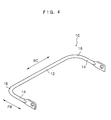
- Fig. 1 shows a front view of a vehicle stabilizer for high stress 10 (hereinafter, stabilizer 10) according to an embodiment of the present invention.
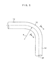
- Fig. 2 shows a side view of the stabilizer 10.
- the stabilizer 10 is molded such that a hot-bending process is conducted on a solid round steel bar, and immediately, a quench-and-temper process is conducted thereon, and is adapted for the use under high stress of 500MPa or more.
- This stabilizer 10 is formed into a complicated configuration in which a plurality of portions is bent at an intermediate portion in a lengthwise direction of the stabilizer 10 in order to avoid the stabilizer 10 from interfering with a lower structure and a suspension of a vehicle body when attached to a vehicle.
- the stabilizer 10 comprises, in a state of being attached to the vehicle, a torsion portion 12 extending in a widthwise direction (in a direction of arrow WC) of a vehicle and arm portions 14 extending from both left and right end portions of the torsion portion 12 in a front and back direction of a vehicle (in a direction of arrow FR).
- Two bending portions 18, each of which is bent in a crank shape, are provided at lengthwise intermediate portions of the torsion portion 12.
- Bending portions 20, each of which is bent in a circular arc shape are provided respectively at a lengthwise intermediate portion of the arm portions 14.
- Bending potions 16, each of which is formed in a circular arc shape are provided at continuous portions, each of which is formed between the torsion portion 12 and each arm portion 14.
- a flat portion what we call, "tool mark" 22 is formed at an outer periphery of each bending portion 16 due to contacting with a mold during the hot-bending process, and a cross section of the bending portion 16 is made flat to have substantially D shape. Further, although it is not shown, tool marks are also formed at the bending portions 18 and 20 in the same manner as in the bending portion 16. In order to simplify the explanation of bending portions, the bending portion 16 is representatively exemplified and a description thereof will be made, hereinafter.
- Fig. 6 shows a perspective view of a test piece 50 which was employed for a fatigue test of the stabilizer 10 according to the present embodiment.
- the test piece 50 was made such that a round bar i.e., JIS spring steel material "SUP9" having a predetermined material diameter was subjected to a hot-bending process, and formed into a substantially U shape, and was immediately subjected to a quench-and-temper process.
- a length of a torsion portion 52 was set to 800 mm, and a length of each of arm portions 54 at both sides was set to 400 mm.
- sixteen test pieces 50 in total numbered from A1 to A8 and from B1 to B8, were prepared by varying a bending portion 56 of each of the test pieces 50 in shapes (values of the radius of bending R, the flat rate ⁇ of the cross section, and the like). Further, although it is not shown, at the bending portions 56 of the test pieces 50, in the same manner as the bending portion 16 of the stabilizer 10, tool marks were formed during the hot-bending process.
- test pieces 50 numbered from A1 to A8 are formed in a state that shapes of the bending portions 56 suffice conditions: 0 ⁇ 4, and ( ⁇ d/R) ⁇ 2 (the present invention).
- each of the bending portions 56 of the test pieces 50 numbered from A1 to A8 is equivalent to the bending portion 16 of the stabilizer 10.
- the test pieces 50 numbered from B1 to B8 are formed in a state in which shapes of the bending portions 56 do not suffice the conditions: 0 ⁇ 4, and ( ⁇ d/R) ⁇ 2 (the comparative example).
- a method for a fatigue test is such that the torsion portion 52 of the test piece 50 is supported at two points thereof, one of the arm portions 54 is horizontally fixed, the other is repeatedly connected via a rotational pin to a test device, a repeated vertical load is applied to the other arm portion 54, and the number of load applications (repetitions), at which number the bending portion 56 between the other of the arm portions 54 and the torsion portion 52 is broken, is counted.
- two types of stresses that are applied to the arm portion 54 of the test piece 50 were 500MPa and 800MPa, respectively.
- test pieces 50 numbered from A1 to A4 and B1 to B4 are provided for the test under the stress of 500MPa, and the test pieces 50 numbered A5 to A8 and B5 to B8 are provided for the test under the stress of 800MPa. Further, an angle at which the other arm portion 54 is bent was set within a range of from 90 to 100 degrees.
- measurement results from the fatigue test under the stress of 550MPa are shown in table 2.
- a graph of relationship between the flat rate ⁇ and the number of repetitions of breakage (the number of repetitions at a time of breakage) in table 2 is shown in Fig. 7, and a graph of relationship between ( ⁇ ⁇ d/R) and the number of repetitions of breakage in table 2 is shown in Fig. 8.
- ⁇ marks express measurement results from the test pieces 50 (numbered from A1 to A4) in which the configurations of the bending portions 56 suffice the conditions: 0 ⁇ 4, and ( ⁇ d/R) ⁇ 2
- ⁇ marks express measurement results from the test pieces 50 (numbered from B1 to B4) in which the configurations of the bending portions 56 do not suffice the conditions: 0 ⁇ 4, and ( ⁇ d/R) ⁇ 2.
- a graph of relationship between the flat rate ⁇ and the number of repetitions of breakage in table 3 is shown in Fig. 9, and a graph of relationship between ( ⁇ ⁇ d/R) and the number of repetitions of breakage in table 3 is shown in Fig. 10.
- ⁇ marks express measurement results from the test pieces 50 (numbered from A5 to A8) in which the configurations of the bending portions 56 suffice the conditions: 0 ⁇ 4, and ( ⁇ d/R) ⁇ 2
- ⁇ marks express measurement results from the test pieces 50 (numbered from B5 to B8) in which the configurations of the bending portions 56 do not suffice the conditions: 0 ⁇ 4, and ( ⁇ d/R) ⁇ 2.
- the bending portions 18 and 20 are also formed so as to suffice the conditions: 0 ⁇ 4 and ( ⁇ d/R) ⁇ 2.
Landscapes
- Engineering & Computer Science (AREA)
- Mechanical Engineering (AREA)
- Vehicle Body Suspensions (AREA)
- Investigating Strength Of Materials By Application Of Mechanical Stress (AREA)
Abstract
Description
- The present invention relates to a solid vehicle stabilizer for high stress, the stabilizer being applicable under high stress, that is able to reduce an amount in which a vehicle body is rolled during a turning of a vehicle such as an automobile, and improves riding comfort for a vehicle passenger, and enhances stability of the vehicle body.
- Typically, in order to reduce an amount of a vehicle roll that occurs during a vehicle cornering, a vehicle such as an automobile is provided with a stabilizer that is formed by conducting a hot-bending process on a spring steel material or the like (see Document 1).
Such a stabilizer has a complicated configuration in which a plurality of points at a lengthwise intermediate portion of the stabilizer is bent in order to avoid the stabilizer from interfering with a lower portion and a suspension of a vehicle body when the stabilizer is attached to a vehicle. However, generally, the stabilizer comprises a torsion portion that is existed to extend in a vehicle widthwise direction in a state of being attached to the vehicle and arm portions extending respectively from both left and right end portions of the torsion portion in a front and back direction of the vehicle. Further, a continuous portion spanning between the torsion portion and each of the arm portions is formed into a circular arc shape and is provided with a bending portion.
Here, the torsion portion is connected at the vehicle body side through a rubber bush, a bracket or the like. Link members are also connected to tip end portions of the arm portions by using bolts or the like, and the arm portions are connected, via the link members, to each member at a side of an axle such as a suspension arm or the like. Then, during a vehicle cornering, vertical loads in directions opposite to each other are applied to the tip end portions of the respective arm portions so that the respective arm portions are deflected in directions opposite to each other, and the torsion portion is twisted due to a moment. Accordingly, this stabilizer is structured to allow a resilient reaction force to act on the member at the axle side and, suppress the roll of the vehicle body.
Therefore, high load is repeatedly applied to such a stabilizer, which causes a problem with durability such as fatigue life. In particular, a maximum stress that is applied to the stabilizer tends to generate on the bending portion. However, generally, due to contacting with a mold during the hot-bending process, a flat portion, what is called, a "tool mark" is formed at the bending portion, therefore, the cross section of the bending portion is made flat to form a substantially D-shape. For this reason, when the stabilizer is actually attached to a vehicle for practical use, stress is often concentrated on the "tool mark" of the bending portion, which often causes the stabilizer to be broken due to the concentration of stress. Accordingly, in order to improve the durability of the stabilizer, fatigue life of the bending portion must be maintained as long as possible.
In particular, due to an increase of family of a vehicle having a large vehicle height such as a so-called SUV (sports utility vehicle), high roll rigidity of the stabilizer is highly required. Further, in order to obtain a crushable zone in the vehicle, it is also required that arm portions should be made as short as possible. For this reason, there is a tendency that stress applied to the bending portion increases more and more. Consequently, in such a stabilizer used under high stress as described above, further improvement in durability is required. - In view of the aforementioned facts, an object of the present invention is to provide a vehicle stabilizer for high stress in which fatigue life of a bending portion can be prolonged and which can exhibit excellent durability.
- In order solve the aforementioned problems, the present invention is a vehicle stabilizer for high stress that is formed by conducting a hot-bending process on a solid round steel bar material, wherein a bending portion is molded in a state which satisfies conditions:

in which d represents a material diameter of the solid round steel bar material, R represents a radius of bending of the bending portion, d1 represents a short radius of a cross section of the bending portion, d2 represents a long radius of the cross section of the bending portion, and a flat rate φ of the cross section of the bending portion is represented by the following equation:
The present invention is the vehicle stabilizer for high stress in which a radius of bending R, a flat rate φ of a cross section of the bending portion, and a material diameter d before the bending process are set within predetermined ranges of values at the bending portion on which a maximum stress is generally applied and which is a most fragile portion. Here, the material diameter d, and the radius of bending R of the bending portion are values independently determined for each vehicle family. Namely, in the vehicle stabilizer for high stress of the present invention, the flat rate φ of a cross section of the bending portion is determined within a predetermined range of values on the basis of values of the predetermined material diameter d and the radius of bending R of the bending portion. Consequently, it becomes possible to prevent concentration of stress, i.e., shearing stress, occurred at the bending portion when the load is inputted thereto and prevent the vehicle stabilizer from being broken at the bending portion due to the concentration of stress at the bending portion.
Further, the present invention is the vehicle stabilizer for high stress, wherein the vehicle stabilizer for high stress is used under stress of 500MPa or more. - As described above, the vehicle stabilizer for high stress according to the present invention can prolong fatigue life of the bending portion, and improve durability.
-
- [Fig. 1]
Fig.1 is a front view showing a vehicle stabilizer for high stress according to an embodiment of the present invention. - [Fig. 2]
Fig.2 is a side view showing the vehicle stabilizer for high stress according to the present embodiment. - [Fig. 3]
Fig.3 is a perspective view showing a structure of a bending portion of the vehicle stabilizer for high stress according to the present embodiment. - [Fig. 4]
Fig.4 is a cross-sectional view taken along a line A-A of Fig. 3. - [Fig. 5]
Fig.5 is a plan view showing the structure of the bending portion of the vehicle stabilizer for high stress according to the present embodiment. - [Fig. 6]
Fig. 6 is a perspective view showing a test piece applied for a fatigue test of the vehicle stabilizer for high stress according to the present embodiment. - [Fig. 7]
Fig. 7 is a graph illustrating a relationship between a flat rate φ and the number of repetitions of breakage in a case in which stress is 550MPa. - [Fig. 8]
Fig. 8 is a graph illustrating a relationship between (a flat rate φ×a material diameter d/radius of bending R) and the number of repetitions of breakage in a case in which stress is 550MPa. - [Fig. 9]
Fig. 9 is a graph illustrating a relationship between a flat rate φ and the number of repetitions of breakage in a case in which stress is 800MPa. - [Fig.10]
Fig. 10 is a graph illustrating a relationship between (a flat rate φ×a material diameter d/radius of bending R) and the number of repetitions of breakage in a case in which stress is 800MPa. - Fig. 1 shows a front view of a vehicle stabilizer for high stress 10 (hereinafter, stabilizer 10) according to an embodiment of the present invention. Further, Fig. 2 shows a side view of the
stabilizer 10.
Thestabilizer 10 is molded such that a hot-bending process is conducted on a solid round steel bar, and immediately, a quench-and-temper process is conducted thereon, and is adapted for the use under high stress of 500MPa or more. Thisstabilizer 10 is formed into a complicated configuration in which a plurality of portions is bent at an intermediate portion in a lengthwise direction of thestabilizer 10 in order to avoid thestabilizer 10 from interfering with a lower structure and a suspension of a vehicle body when attached to a vehicle. Thestabilizer 10 comprises, in a state of being attached to the vehicle, atorsion portion 12 extending in a widthwise direction (in a direction of arrow WC) of a vehicle andarm portions 14 extending from both left and right end portions of thetorsion portion 12 in a front and back direction of a vehicle (in a direction of arrow FR). Two bendingportions 18, each of which is bent in a crank shape, are provided at lengthwise intermediate portions of thetorsion portion 12. Bendingportions 20, each of which is bent in a circular arc shape, are provided respectively at a lengthwise intermediate portion of thearm portions 14. Bendingpotions 16, each of which is formed in a circular arc shape, are provided at continuous portions, each of which is formed between thetorsion portion 12 and eacharm portion 14.
As shown in Figs. 3 and 4, a flat portion, what we call, "tool mark" 22 is formed at an outer periphery of eachbending portion 16 due to contacting with a mold during the hot-bending process, and a cross section of thebending portion 16 is made flat to have substantially D shape. Further, although it is not shown, tool marks are also formed at thebending portions bending portion 16. In order to simplify the explanation of bending portions, thebending portion 16 is representatively exemplified and a description thereof will be made, hereinafter.
In thestabilizer 10, the bendingportion 16 is formed into a state which satisfies conditions:
wherein d represents a (material) diameter of the solid round steel bar material, R represents a radius of bending of the bendingportion 16, d1 represents a short radius of a cross section of the bendingportion 16, and d2 represents a long radius of the cross section of the bendingportion 16, and a flat rate φ of the cross section of the bendingportion 16 is represented by the following equation:
Further, the radius of bending R of the bendingportion 16 is a radius of bending which is taken along the centerline SP of the bendingportion 16 as shown in Fig. 5. Moreover, the material diameter d of the solid round steel bar material and the radius of bending R of the bending portion are values individually set for each of vehicle families.
Next, a description of a fatigue test will be made.
Fig. 6 shows a perspective view of a test piece 50 which was employed for a fatigue test of thestabilizer 10 according to the present embodiment.
The test piece 50 was made such that a round bar i.e., JIS spring steel material "SUP9" having a predetermined material diameter was subjected to a hot-bending process, and formed into a substantially U shape, and was immediately subjected to a quench-and-temper process. A length of a torsion portion 52 was set to 800 mm, and a length of each of arm portions 54 at both sides was set to 400 mm. At this time, as seen from table 1 shown below, sixteen test pieces 50 in total, numbered from A1 to A8 and from B1 to B8, were prepared by varying a bending portion 56 of each of the test pieces 50 in shapes (values of the radius of bending R, the flat rate φ of the cross section, and the like). Further, although it is not shown, at the bending portions 56 of the test pieces 50, in the same manner as the bendingportion 16 of thestabilizer 10, tool marks were formed during the hot-bending process. - [Table 1]
Table 1 No material diameter d (mm) radius of bending R (mm) d/R short radius d1 (mm) long radius d2 (mm) flat rateφ (%) φ ×d/R remarks A1 23 65 0.35 22.8 23.0 0.87 0.31 Present Invention A2 23 45 0.51 22.6 23.0 1.74 0.89 A3 26 65 0.40 25.7 26.0 1.15 0.46 A4 26 45 0.58 25.5 26.0 1.92 1.11 A5 23 65 0.35 22.8 23.0 0.87 0.31 A6 23 45 0.51 22.6 23.0 1.74 0.89 A7 26 65 0.40 25.7 26.0 1.15 0.46 A8 26 45 0.58 25.5 26.0 1.92 1.11 B1 23 65 0.35 21.8 23.0 5.22 1.85 Comparative Example B2 23 45 0.51 21.6 23.0 6.09 3.11 B3 26 65 0.40 24.5 26.0 5.77 2.31 B4 26 45 0.58 24.3 26.0 6.54 3.78 B5 23 65 0.35 21.8 23.0 5.22 1.85 B6 23 45 0.51 21.6 23.0 6.09 3.11 B7 26 65 0.40 24.5 26.0 5.77 2.31 B8 26 45 0.58 24.3 26.0 6.54 3.78 - As shown in table 1, the test pieces 50 numbered from A1 to A8 are formed in a state that shapes of the bending portions 56 suffice conditions: 0<φ≦4, and (φ×d/R)≦2 (the present invention). In other words, each of the bending portions 56 of the test pieces 50 numbered from A1 to A8 is equivalent to the bending
portion 16 of thestabilizer 10. On the other hand, the test pieces 50 numbered from B1 to B8 are formed in a state in which shapes of the bending portions 56 do not suffice the conditions: 0<φ≦4, and (φ×d/R)≦2 (the comparative example). On the other hand, a method for a fatigue test is such that the torsion portion 52 of the test piece 50 is supported at two points thereof, one of the arm portions 54 is horizontally fixed, the other is repeatedly connected via a rotational pin to a test device, a repeated vertical load is applied to the other arm portion 54, and the number of load applications (repetitions), at which number the bending portion 56 between the other of the arm portions 54 and the torsion portion 52 is broken, is counted. Moreover, two types of stresses that are applied to the arm portion 54 of the test piece 50 were 500MPa and 800MPa, respectively. The test pieces 50 numbered from A1 to A4 and B1 to B4 are provided for the test under the stress of 500MPa, and the test pieces 50 numbered A5 to A8 and B5 to B8 are provided for the test under the stress of 800MPa. Further, an angle at which the other arm portion 54 is bent was set within a range of from 90 to 100 degrees.
Here, measurement results from the fatigue test under the stress of 550MPa are shown in table 2. - [Table 2]
Table 2 No. flat rateφ (%) φ ×d/R number of repetitions of breakage (_0,000 times) remarks A1 0.87 0.31 33.8 Present Invention A2 1.74 0.89 30.5 A3 1.15 0.46 31.5 A4 1.92 1.11 29.5 B1 5.22 1.85 13.5 Comparative Example B2 6.09 3.11 15.2 B3 5.77 2.31 14.6 B4 6.54 3.78 13.7 - Further, a graph of relationship between the flat rate φ and the number of repetitions of breakage (the number of repetitions at a time of breakage) in table 2 is shown in Fig. 7, and a graph of relationship between (φ ×d/R) and the number of repetitions of breakage in table 2 is shown in Fig. 8. Moreover, in Figs. 7 and 8, ● marks express measurement results from the test pieces 50 (numbered from A1 to A4) in which the configurations of the bending portions 56 suffice the conditions: 0<φ≦4, and (φ×d/R)≦2, and Δ marks express measurement results from the test pieces 50 (numbered from B1 to B4) in which the configurations of the bending portions 56 do not suffice the conditions: 0<φ≦4, and (φ×d/R)≦2. On the basis of table 2, and Figs. 4 and 5, under the load stress of 550MPa, regarding the test pieces 50 (numbered from A1 to A4), in which the configurations of the bending portions 56 suffice both conditions: 0<φ≦4, and (φ×d/R)≦2, it is revealed that the number of repetitions of breakage is 295, 000 times or more. On the other hand, under the load stress of 550MPa, regarding the test pieces 50 (numbered from B1 to B4), in which the configurations of the bending portions 56 do not suffice the conditions: 0<φ ≦ 4, and (φ×d/R) ≦ 2, it is revealed that the number of repetitions of breakage are 1 52,000 times or less.
Consequently, under the stress of 550MPa, as long as the bending portion 56 is formed into a configuration that suffices both conditions: 0<φ≦4, and (φ×d/R)≦2, it is noted that the number of repetitions of breakage (fatigue life) of the bending portion 56 increases rapidly.
Next, measurement results from the fatigue test under the stress of 800MPa are shown in table 3. - [Table 3]
Table 3 No. flat rateφ (%) φ ×d/R number of repetitions of breakage (_0,000 times) remarks A5 0.87 0.31 3.2 Present Invention A6 1.74 0.89 3.7 A7 1.15 0.46 4.5 A8 1.92 1.11 4.0 B5 5.22 1.85 2.1 Comparative Example B6 6.09 3.11 1.5 B7 5.77 2.31 1.3 B8 6.54 3.78 1.2 - Further, a graph of relationship between the flat rate φ and the number of repetitions of breakage in table 3 is shown in Fig. 9, and a graph of relationship between (φ ×d/R) and the number of repetitions of breakage in table 3 is shown in Fig. 10. Moreover, in Figs. 9 and 10, ● marks express measurement results from the test pieces 50 (numbered from A5 to A8) in which the configurations of the bending portions 56 suffice the conditions: 0<φ≦4, and (φ×d/R)≦2, and Δ marks express measurement results from the test pieces 50 (numbered from B5 to B8) in which the configurations of the bending portions 56 do not suffice the conditions: 0<φ≦4, and (φ×d/R)≦2. On the basis of table 3, and Figs. 9 and 10, under the stress of 800MPa, regarding the test pieces 50 (numbered from A5 to A8), in which the configurations of the bending portions 56 suffice both
conditions 0<φ≦4, and (φ×d/R) ≦ 2, it is revealed that the number of repetitions of breakage is 32, 000 times or more. On the other hand, under the stress of 800MPa, regarding the test pieces 50 (numbered from B5 to B8) that have the bending portions 56 whose configurations do not suffice the conditions: 0<φ≦4, and (φ×d/R)≦2, it is revealed that the number of repetitions of breakage is 21,000 times or less.
Consequently, also, under the stress of 800MPa, as long as the bending portion 56 is formed into a state that suffices bothconditions 0<φ≦4, and (φ×d/R)≦2, the number of repetitions of breakage (fatigue life) of the bending portion 56 increases rapidly.
From the above-described results, it is revealed that, in thesolid stabilizer 10 which has received a heat treatment by a hot-bending process and is to be used under the stress of 500MPa or more, the relationship among the flat rate φ of the bendingportion 16, the material diameter d before the bending process, the radius of bending R of the bendingportion 16 suffices both 0<φ≦4 and (φ×d/R)≦2, it is ensured that thestabilizer 10 having excellent durability can be obtained, and that the present invention can exhibit excellent efficiency.
Thus, in the vehicle stabilizer for high stress according to the present invention, fatigue life of the bendingportion 16 can be increased, and durability can improve.
Further, in the aforementioned embodiment, although relationship between the configuration of the bendingportion 16 of thevehicle stabilizer 10 for high stress and fragile life has been explained, the bendingportions -
- 10:
- vehicle stabilizer for high stress
- 12:
- torsion portion
- 14:
- arm portion
- 16:
- bending portion
- 18:
- bending portion
- 20:
- bending portion
- 22:
- tool mark
- R:
- radius of bending
- d:
- material diameter
- d1:
- short radius
- d2:
- long radius
- φ :
- flat rate
- 50:
- test piece
- 52:
- torsion portion
- 54:
- arm portion
- 56:
- bending portion
Claims (2)
- A vehicle stabilizer for high stress that is formed by conducting a hot-bending process on a solid round steel bar material, wherein a bending portion is formed in a state which satisfies conditions:

in which d represents a material diameter of the solid round steel bar material, R represents a radius of bending of the bending portion, d1 represents a short radius of a cross section of the bending portion, d2 represents a long radius of the cross section of the bending portion, and a flat rate φ of the cross section of the bending portion is represented by the following equation:
- The vehicle stabilizer for high stress according to claim 1, wherein the vehicle stabilizer for high stress is used under stress of 500MPa or more.
Applications Claiming Priority (2)
| Application Number | Priority Date | Filing Date | Title |
|---|---|---|---|
| JP2003301402A JP4087765B2 (en) | 2003-08-26 | 2003-08-26 | High stress stabilizer for vehicles |
| PCT/JP2004/012011 WO2005018966A1 (en) | 2003-08-26 | 2004-08-20 | High stress stabilizer for vehicle |
Publications (3)
| Publication Number | Publication Date |
|---|---|
| EP1661741A1 true EP1661741A1 (en) | 2006-05-31 |
| EP1661741A4 EP1661741A4 (en) | 2006-12-06 |
| EP1661741B1 EP1661741B1 (en) | 2010-06-09 |
Family
ID=34213889
Family Applications (1)
| Application Number | Title | Priority Date | Filing Date |
|---|---|---|---|
| EP04771972A Expired - Lifetime EP1661741B1 (en) | 2003-08-26 | 2004-08-20 | High stress stabilizer for vehicle |
Country Status (7)
| Country | Link |
|---|---|
| US (1) | US7500660B2 (en) |
| EP (1) | EP1661741B1 (en) |
| JP (1) | JP4087765B2 (en) |
| CN (1) | CN100447002C (en) |
| CA (1) | CA2537253C (en) |
| DE (1) | DE602004027639D1 (en) |
| WO (1) | WO2005018966A1 (en) |
Families Citing this family (5)
| Publication number | Priority date | Publication date | Assignee | Title |
|---|---|---|---|---|
| US2840037A (en) * | 1954-04-02 | 1958-06-24 | Howard V Schweitzer | Mechanical movement for coating apparatus |
| DE10326858A1 (en) * | 2003-06-14 | 2005-01-13 | Daimlerchrysler Ag | Watt strut |
| US20070257462A1 (en) * | 2006-05-02 | 2007-11-08 | Meritor Suspension Systems Company, Us | Die cast stabilizer bar ends |
| DE102006054874A1 (en) * | 2006-11-20 | 2008-05-21 | Zf Friedrichshafen Ag | Stabilizer device with Radführungslenker |
| CN107725650A (en) * | 2017-09-28 | 2018-02-23 | 浙江华莎驰机械有限公司 | A kind of torsion-type dynamic mechanically connector |
Family Cites Families (14)
| Publication number | Priority date | Publication date | Assignee | Title |
|---|---|---|---|---|
| US4231555A (en) * | 1978-06-12 | 1980-11-04 | Horikiri Spring Manufacturing Co., Ltd. | Bar-shaped torsion spring |
| JPS5642741A (en) * | 1979-09-18 | 1981-04-21 | Nhk Spring Co Ltd | Hollow stabilizer for vehicle |
| FI90635C (en) * | 1990-03-05 | 1994-03-10 | Imatra Steel Oy Ab | Method and apparatus for manufacturing anti-roll bars |
| JPH0641937A (en) | 1992-07-22 | 1994-02-15 | Kaishin:Kk | Two-stage gate device |
| JPH0641937U (en) | 1992-11-13 | 1994-06-03 | 鈴木金属工業株式会社 | Molding pin for coil spring molding |
| JP3082558B2 (en) | 1994-01-28 | 2000-08-28 | 日本鋼管株式会社 | Hollow stabilizer with excellent durability |
| JPH07266837A (en) * | 1994-03-29 | 1995-10-17 | Horikiri Bane Seisakusho:Kk | Hollow stabilizer manufacturing method |
| JPH08142632A (en) * | 1994-11-16 | 1996-06-04 | Nhk Spring Co Ltd | Hollow stabilizer |
| EP0878334B1 (en) * | 1997-05-12 | 2003-09-24 | Firma Muhr und Bender | Stabilizer |
| JP3814710B2 (en) | 1998-06-30 | 2006-08-30 | Jfe条鋼株式会社 | Manufacturing method of steel material for high strength cold forming non-tempered buffer / restoration mechanism member |
| JP2000024737A (en) * | 1998-07-14 | 2000-01-25 | Mitsubishi Motors Corp | Manufacturing method of stabilizer bar |
| US6318710B1 (en) * | 2000-11-21 | 2001-11-20 | Meritor Suspension Systems Company | Stabilizer bars with variable cross-sectional properties |
| JP2002331326A (en) * | 2001-03-08 | 2002-11-19 | Nhk Spring Co Ltd | Hollow stabilizer and method of manufacturing the same |
| JP2002283824A (en) | 2001-03-29 | 2002-10-03 | Mitsubishi Steel Mfg Co Ltd | Stabilizer for vehicle |
-
2003
- 2003-08-26 JP JP2003301402A patent/JP4087765B2/en not_active Expired - Lifetime
-
2004
- 2004-08-20 EP EP04771972A patent/EP1661741B1/en not_active Expired - Lifetime
- 2004-08-20 CA CA2537253A patent/CA2537253C/en not_active Expired - Lifetime
- 2004-08-20 US US10/569,787 patent/US7500660B2/en not_active Expired - Lifetime
- 2004-08-20 DE DE602004027639T patent/DE602004027639D1/en not_active Expired - Lifetime
- 2004-08-20 WO PCT/JP2004/012011 patent/WO2005018966A1/en not_active Ceased
- 2004-08-20 CN CNB2004800244369A patent/CN100447002C/en not_active Expired - Lifetime
Also Published As
| Publication number | Publication date |
|---|---|
| US20070063473A1 (en) | 2007-03-22 |
| WO2005018966A1 (en) | 2005-03-03 |
| US7500660B2 (en) | 2009-03-10 |
| JP2005066661A (en) | 2005-03-17 |
| DE602004027639D1 (en) | 2010-07-22 |
| CA2537253A1 (en) | 2005-03-03 |
| JP4087765B2 (en) | 2008-05-21 |
| CN1842423A (en) | 2006-10-04 |
| HK1097491A1 (en) | 2007-08-24 |
| EP1661741A4 (en) | 2006-12-06 |
| CA2537253C (en) | 2010-04-27 |
| CN100447002C (en) | 2008-12-31 |
| EP1661741B1 (en) | 2010-06-09 |
Similar Documents
| Publication | Publication Date | Title |
|---|---|---|
| US7828308B2 (en) | Stabiliser bar for a vehicle | |
| EP0933241B1 (en) | Stabiliser | |
| US8616567B2 (en) | Vehicle suspension apparatus | |
| EP0965467B1 (en) | Leaf spring suspension system | |
| EP2969611B1 (en) | Rear twist beam with bulged middle section | |
| EP1661741B1 (en) | High stress stabilizer for vehicle | |
| US5246248A (en) | Vehicle rear suspension apparatus | |
| CN111051727A (en) | Bushing | |
| EP0825042B1 (en) | Stabilizer system | |
| DE102018201435B4 (en) | Axle suspension | |
| CN113682100B (en) | Stabilizer bar and vehicle | |
| EP0527139B1 (en) | High strength cord | |
| EP1522433B1 (en) | Stabilizer bar lateral retainer collar | |
| HK1097491B (en) | High stress stabilizer for vehicle | |
| US4775166A (en) | Vehicle suspension beam-to-axle connection | |
| JP2726710B2 (en) | FRP member | |
| KR100902836B1 (en) | Tubular torsion beam for rear suspension of vehicle | |
| Wittek et al. | Stabilizer bars. Part 1: Calculations and construction | |
| DE102019209977A1 (en) | Axle suspension for a vehicle | |
| KR20140008114A (en) | Producing method for stabilizer bar having multiple steps | |
| KR100908175B1 (en) | Car Stabilizer Bar | |
| KR100820474B1 (en) | Wheel alignment adjustment device for vehicle with leaf spring | |
| WO2005084970A1 (en) | Torsion bar | |
| KR20070032591A (en) | Leaf spring device | |
| DE102019209917A1 (en) | Axle suspension for a vehicle |
Legal Events
| Date | Code | Title | Description |
|---|---|---|---|
| PUAI | Public reference made under article 153(3) epc to a published international application that has entered the european phase |
Free format text: ORIGINAL CODE: 0009012 |
|
| 17P | Request for examination filed |
Effective date: 20060301 |
|
| AK | Designated contracting states |
Kind code of ref document: A1 Designated state(s): DE FR GB |
|
| DAX | Request for extension of the european patent (deleted) | ||
| RBV | Designated contracting states (corrected) |
Designated state(s): DE FR GB |
|
| A4 | Supplementary search report drawn up and despatched |
Effective date: 20061107 |
|
| GRAP | Despatch of communication of intention to grant a patent |
Free format text: ORIGINAL CODE: EPIDOSNIGR1 |
|
| GRAS | Grant fee paid |
Free format text: ORIGINAL CODE: EPIDOSNIGR3 |
|
| GRAA | (expected) grant |
Free format text: ORIGINAL CODE: 0009210 |
|
| AK | Designated contracting states |
Kind code of ref document: B1 Designated state(s): DE FR GB |
|
| REF | Corresponds to: |
Ref document number: 602004027639 Country of ref document: DE Date of ref document: 20100722 Kind code of ref document: P |
|
| PLBE | No opposition filed within time limit |
Free format text: ORIGINAL CODE: 0009261 |
|
| STAA | Information on the status of an ep patent application or granted ep patent |
Free format text: STATUS: NO OPPOSITION FILED WITHIN TIME LIMIT |
|
| 26N | No opposition filed |
Effective date: 20110310 |
|
| REG | Reference to a national code |
Ref country code: DE Ref legal event code: R097 Ref document number: 602004027639 Country of ref document: DE Effective date: 20110309 |
|
| REG | Reference to a national code |
Ref country code: FR Ref legal event code: PLFP Year of fee payment: 12 |
|
| REG | Reference to a national code |
Ref country code: FR Ref legal event code: PLFP Year of fee payment: 13 |
|
| REG | Reference to a national code |
Ref country code: FR Ref legal event code: PLFP Year of fee payment: 14 |
|
| REG | Reference to a national code |
Ref country code: FR Ref legal event code: PLFP Year of fee payment: 15 |
|
| PGFP | Annual fee paid to national office [announced via postgrant information from national office to epo] |
Ref country code: GB Payment date: 20230629 Year of fee payment: 20 |
|
| PGFP | Annual fee paid to national office [announced via postgrant information from national office to epo] |
Ref country code: FR Payment date: 20230703 Year of fee payment: 20 Ref country code: DE Payment date: 20230627 Year of fee payment: 20 |
|
| REG | Reference to a national code |
Ref country code: DE Ref legal event code: R071 Ref document number: 602004027639 Country of ref document: DE |
|
| REG | Reference to a national code |
Ref country code: GB Ref legal event code: PE20 Expiry date: 20240819 |
|
| PG25 | Lapsed in a contracting state [announced via postgrant information from national office to epo] |
Ref country code: GB Free format text: LAPSE BECAUSE OF EXPIRATION OF PROTECTION Effective date: 20240819 |
|
| PG25 | Lapsed in a contracting state [announced via postgrant information from national office to epo] |
Ref country code: GB Free format text: LAPSE BECAUSE OF EXPIRATION OF PROTECTION Effective date: 20240819 |