EP1661607B1 - Transparentes Kantenträger für Eislaufschuhe - Google Patents
Transparentes Kantenträger für Eislaufschuhe Download PDFInfo
- Publication number
- EP1661607B1 EP1661607B1 EP20040292779 EP04292779A EP1661607B1 EP 1661607 B1 EP1661607 B1 EP 1661607B1 EP 20040292779 EP20040292779 EP 20040292779 EP 04292779 A EP04292779 A EP 04292779A EP 1661607 B1 EP1661607 B1 EP 1661607B1
- Authority
- EP
- European Patent Office
- Prior art keywords
- blade holder
- graphical element
- blade
- clear material
- inner surfaces
- Prior art date
- Legal status (The legal status is an assumption and is not a legal conclusion. Google has not performed a legal analysis and makes no representation as to the accuracy of the status listed.)
- Ceased
Links
- 239000000463 material Substances 0.000 claims description 43
- NJPPVKZQTLUDBO-UHFFFAOYSA-N novaluron Chemical compound C1=C(Cl)C(OC(F)(F)C(OC(F)(F)F)F)=CC=C1NC(=O)NC(=O)C1=C(F)C=CC=C1F NJPPVKZQTLUDBO-UHFFFAOYSA-N 0.000 claims description 16
- 239000003973 paint Substances 0.000 claims description 4
- 229920000515 polycarbonate Polymers 0.000 claims description 4
- 239000004417 polycarbonate Substances 0.000 claims description 4
- -1 polyethylene Polymers 0.000 claims description 4
- 239000006260 foam Substances 0.000 claims description 3
- 238000001746 injection moulding Methods 0.000 claims description 3
- 229920002635 polyurethane Polymers 0.000 claims description 3
- 239000004814 polyurethane Substances 0.000 claims description 3
- OKTJSMMVPCPJKN-UHFFFAOYSA-N Carbon Chemical compound [C] OKTJSMMVPCPJKN-UHFFFAOYSA-N 0.000 claims description 2
- 229920000271 Kevlar® Polymers 0.000 claims description 2
- 239000004698 Polyethylene Substances 0.000 claims description 2
- 239000004743 Polypropylene Substances 0.000 claims description 2
- 239000004793 Polystyrene Substances 0.000 claims description 2
- RTAQQCXQSZGOHL-UHFFFAOYSA-N Titanium Chemical compound [Ti] RTAQQCXQSZGOHL-UHFFFAOYSA-N 0.000 claims description 2
- NIXOWILDQLNWCW-UHFFFAOYSA-N acrylic acid group Chemical group C(C=C)(=O)O NIXOWILDQLNWCW-UHFFFAOYSA-N 0.000 claims description 2
- XAGFODPZIPBFFR-UHFFFAOYSA-N aluminium Chemical compound [Al] XAGFODPZIPBFFR-UHFFFAOYSA-N 0.000 claims description 2
- 229910052782 aluminium Inorganic materials 0.000 claims description 2
- 229910052799 carbon Inorganic materials 0.000 claims description 2
- 239000011111 cardboard Substances 0.000 claims description 2
- 239000011152 fibreglass Substances 0.000 claims description 2
- 239000004761 kevlar Substances 0.000 claims description 2
- 239000000123 paper Substances 0.000 claims description 2
- 229920000573 polyethylene Polymers 0.000 claims description 2
- 229920000642 polymer Polymers 0.000 claims description 2
- 229920001155 polypropylene Polymers 0.000 claims description 2
- 229920002223 polystyrene Polymers 0.000 claims description 2
- 238000003856 thermoforming Methods 0.000 claims description 2
- 229910052719 titanium Inorganic materials 0.000 claims description 2
- 239000010936 titanium Substances 0.000 claims description 2
- 238000010102 injection blow moulding Methods 0.000 claims 1
- 239000008258 liquid foam Substances 0.000 claims 1
- 238000000034 method Methods 0.000 description 18
- 230000000007 visual effect Effects 0.000 description 3
- 238000005299 abrasion Methods 0.000 description 1
- 238000000071 blow moulding Methods 0.000 description 1
- 239000003086 colorant Substances 0.000 description 1
- 239000002131 composite material Substances 0.000 description 1
- 238000010276 construction Methods 0.000 description 1
- 238000013461 design Methods 0.000 description 1
- 230000006866 deterioration Effects 0.000 description 1
- 239000007788 liquid Substances 0.000 description 1
- 238000012986 modification Methods 0.000 description 1
- 230000004048 modification Effects 0.000 description 1
- 238000010422 painting Methods 0.000 description 1
- 238000012552 review Methods 0.000 description 1
- 238000012546 transfer Methods 0.000 description 1
- 239000012780 transparent material Substances 0.000 description 1
Images


Classifications
-
- A—HUMAN NECESSITIES
- A63—SPORTS; GAMES; AMUSEMENTS
- A63C—SKATES; SKIS; ROLLER SKATES; DESIGN OR LAYOUT OF COURTS, RINKS OR THE LIKE
- A63C1/00—Skates
-
- A—HUMAN NECESSITIES
- A63—SPORTS; GAMES; AMUSEMENTS
- A63C—SKATES; SKIS; ROLLER SKATES; DESIGN OR LAYOUT OF COURTS, RINKS OR THE LIKE
- A63C1/00—Skates
- A63C1/30—Skates with special blades
-
- A—HUMAN NECESSITIES
- A63—SPORTS; GAMES; AMUSEMENTS
- A63C—SKATES; SKIS; ROLLER SKATES; DESIGN OR LAYOUT OF COURTS, RINKS OR THE LIKE
- A63C2203/00—Special features of skates, skis, roller-skates, snowboards and courts
- A63C2203/42—Details of chassis of ice or roller skates, of decks of skateboards
Definitions
- the present invention relates to a clear blade holder for an ice skate.
- An ice skate typically includes a skate boot for receiving a foot of a user, an ice skate blade for engaging an ice surface, and a blade holder holding the ice skate blade and attached to the skate boot.
- a blade holder is usually made of a rigid polymeric material and is hollow in construction, for weight considerations. Normally, a blade holder is opaque and of a specific color such as black or white. Some blade holders have been made of transparent material but have enjoyed limited success in the industry.
- International Patent Application WO 03/002216 relates to a transparent blade holder assembly configured so that a user can adjust the pitch of the ice blade between a plurality of discrete pitch positions. The pitch is adjusted by locking the ice blade at a desired angle relative to the blade holder.
- the invention provides a blade holder comprising a body having a top portion for attachment to a skate boot and a bottom portion for receiving an ice skate blade.
- the body is at least partly made of a clear material and defines a cavity.
- the blade holder also comprises a graphical element inside the cavity and visible through the clear material.
- the invention provides a blade holder comprising a body at least partly made of a clear material and comprising a bottom portion having a longitudinal slot for receiving an ice skate blade, a front pedestal with a front inner surface, a rear pedestal with a rear inner surface and a bridge portion interconnecting the front and rear pedestals, the front and rear inner surfaces defining respective front and rear cavities.
- the blade holder has a graphical element inside one of the front and rear cavities, the graphical element being visible through the clear material.
- the invention provides a method of customizing a blade holder.
- the method comprises providing to a customer a blade holder body being at least partly made of a clear material and defining a cavity.
- the method also comprises providing to the customer a plurality of graphical elements, and selecting a graphical element from the plurality of graphical elements.
- the method further comprises mounting the graphical element inside the cavity of the blade holder body such that the graphical element is visible through the clear material.
- the invention provides a method of customizing a blade holder.
- the method comprises providing to a customer a blade holder body being at least partly made of a clear material and comprising a front pedestal with a front inner surface, a rear pedestal with a rear inner surface, and a bridge portion interconnecting the front and rear pedestals, the front and rear inner surfaces defining respective front and rear cavities.
- the method also comprises providing to the customer a plurality of graphical elements, and selecting a graphical element from the plurality of graphical elements.
- the method further comprises mounting the graphical element inside one of the front and rear cavities such that the graphical element is visible through the clear material.
- the invention provides a method of customizing a blade holder.
- the method comprises providing to a customer a blade holder body being at least partly made of a clear material and comprising a front pedestal with a front inner surface, a rear pedestal with a rear inner surface, and a bridge portion interconnecting the front and rear pedestals, the front and rear inner surfaces defining respective front and rear cavities.
- the method also comprises providing to the customer a plurality of graphical elements, and selecting a graphical element selected from the plurality of graphical elements.
- the method further comprises affixing the graphical element on one of the front and rear surfaces such that the graphical element is visible through the clear material.
- the invention provides a method of customizing a blade holder.
- the method comprises providing to a customer a blade holder body being at least partly made of a clear material and comprising a front pedestal with a front inner surface, a rear pedestal with a rear inner surface, and a bridge portion interconnecting the front and rear pedestals, the front and rear inner surfaces defining respective front and rear cavities.
- the method also comprises providing to the customer a plurality of graphical elements, and selecting a graphical element from the plurality of graphical elements.
- the method further comprises painting the graphical element on one of the front and rear surfaces such that the graphical element is visible through the clear material.
- FIG 1 shows an ice skate 10 having a blade holder 12 in accordance with an embodiment of the invention.
- the blade holder 12 has an ice skate blade 14 and is attached to a skate boot 16 of the ice skate 10.
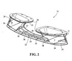
- the blade holder 12 comprises a body 13 having a top portion 20 for attachment to the skate boot 16 and a bottom portion 22 for receiving the ice skate blade 14.
- the body 13 has a front portion 24, a rear portion 26, and a bridge portion 28 interconnecting the front portion 24 and the rear portion 26.
- the front portion 24 is configured as a front pedestal
- the rear portion 26 is configured as a rear pedestal
- the bridge portion 28 has a plurality of apertures 29 for reducing the weight of the body 13 of the blade holder 12.
- the upper edges of the apertures 29 follow a concave imaginary line while the lower edges of the apertures 29 follow a generally straight imaginary line.
- the top portion 20 has a front top portion 21 located on the front portion 24 and a rear top portion 23 located on the rear portion 26. Each one of the front top portion 21 and the rear top portion 23 is adapted to be attached to a sole of the skate boot 16 using fasteners such as rivets, bolts, or other suitable fasteners.
- the bottom portion 22 has a longitudinal slot 25 for receiving the ice skate blade 14.
- the front portion 24 is made of a clear material and defines a front cavity 30.
- the rear portion 26 is also made of the clear material and defines a rear cavity 32.
- the entire body 13 of the blade holder 12 is made of the clear material.
- only certain portions of the body 13 of the blade holder 12 may be made of a clear material while other portions may not be made of a clear material.
- each one of the front portion 24 and the rear portion 26 may be made of a clear material while the bridge portion 28 may not be made of a clear material.
- the clear material is a material capable of being seen through.
- the clear material can be colorless or colored.
- the clear material can include a first region characterized by a first degree of transparency and a second region characterized by a second degree of transparency different from the first degree of transparency.
- the different degrees of transparency can be achieved, for instance, by a different surface finish or thickness of the first and second regions.
- the clear material may be a polymeric material such as, Acrylic, clear polymer or polycarbonate.
- the body 13 of the blade holder 12 can be manufactured using known processes, including but not limited to an injection molding process.
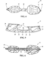
- the blade holder 12 also comprises a front graphical element 34 inside the front cavity 30 and visible through the clear material of the front portion 24, and a rear graphical element 36 inside the rear cavity 32 and visible through the clear material of the rear portion 26. More specifically, the front graphical element 34 is characterized by at least one of a colored area, a mark, a symbol, and a logo visible through the clear material of the front portion 24. Similarly, the rear graphical element 36 is characterized by at least one of a colored area, a mark, a symbol, and a logo visible through the clear material of the rear portion 26.
- the front graphical element 34 is a front insert 38 disposed inside of the front cavity 30, and the rear graphical element 36 is a rear insert 40 disposed inside of the rear cavity 32.
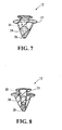
- the front insert 38 may have a contour following an inner surface 42 of the front portion 24 defining the front cavity 30.
- the front insert 38 may also have a flange 48 that at least partially overlies the front top portion 21 such that attachment of the front top portion 21 to the sole of the skate boot 14 secures the front insert 38 inside the front cavity 30.
- the front insert 38 may be affixed, for instance by being glued, to the inner surface 42 of the front portion 24.
- the rear insert 40 may have a contour following an inner surface 44 of the rear portion 26 defining the rear cavity 32, and may have a flange 49 that at least partially overlies the rear top portion 23 such that attachment of the rear top portion 23 to the sole of the skate boot 14 secures the rear insert 40 inside the rear cavity 32.
- the front insert 38 may be of a first color, while the rear insert 40 may have a second color different from the first color.
- various other visual characteristics can be included on each one of the front and rear inserts 38 and 40 without departing from the scope of the claims.
- Each one of the front and rear inserts 38, 40 may be made of a polymeric material such as, polyethylene, polystyrene, polyurethane or polypropylene, polycarbonate. These front and rear inserts 38, 40 may also be made of carbon, fiberglass, titanium, aluminum, Kevlar, paper, cardboard or foam. Alternatively, each one of the front and rear inserts 38, 40 may be made of a composite material or any other suitable material.
- the inserts 38,40 may be manufactured using known processes, including but not limited to thermoforming, blow molding or injection molding.
- the front graphical element 34 is applied directly on the inner surface 42 defining the front cavity 30.
- the rear graphical element 36 is applied directly on the inner surface 44 of the rear portion 26 defining the rear cavity 32.
- each one of the front and rear graphical elements 34, 36 is implemented as paint applied to the inner surfaces 42, 44.
- the paint can be applied using a paintbrush or can be spray-paint.
- the front graphical element 34 is a sticker affixed to the inner surface 42 and, similarly, the rear graphical element 36 is a sticker affixed to the inner surface 44.
- the sticker affixed to each one of the inner surfaces 42, 44 can be any type of sticker, including an ink transfer sticker which is initially applied on a surface and subsequently removed in order to leave a design on the surface.
- the front and rear graphical elements 34, 36 may be colored foam injected in the respective front and rear cavities 30, 32.
- the front and rear graphical elements may be made of a material that can be catalyzed to a liquid foamed state and which will cure relatively rapididly.
- One such material is polyurethane.
- the combination of the clear material and the front and rear graphical elements 34, 36 allows the blade holder 12 to be imparted with various colors and/or other visual characteristics. Furthermore, the front and rear graphical elements 34, 36 are protected from abrasion and deterioration due to impacts since they are respectively located inside the front and rear cavities 30, 32.
- Each one of the front and rear graphical elements 34 and 36 permits a customization of the appearance of the blade holder 12.
- a hockey store can therefore provide to a customer a blade holder body being at least partly made of a clear material and comprising a front pedestal with a front inner surface, a rear pedestal with a rear inner surface and a bridge portion interconnecting said front and rear pedestals, the front and rear inner surfaces defining respective front and rear cavities.
- the hockey store can also provide to the customer a plurality of graphical elements to be mounted into the front and rear cavities or the store may receive from the customer an indication of the graphical elements that are desired to be present on the blade holder.
- the graphical elements that are desired to be present on the blade holder can include the main color(s) associated with the hockey team, the logo of the hockey team, and the number of the player on the hockey team.
- the store can provide the front and rear graphical elements such that the front graphical element includes a colored area containing the main color(s) associated with the hockey team as well as the logo of the hockey team, and the rear graphical element includes a colored area containing the main color(s) associated with the hockey team as well as the number of the hockey player.
- the graphical element may be affixed to the inner surface of the cavity or may be painted on this inner surface.
Landscapes
- Footwear And Its Accessory, Manufacturing Method And Apparatuses (AREA)
Claims (21)
- Kufenhalter mit einem Körper (13), der mindestens teilweise aus einem klaren Material hergestellt ist und aufweist: einen unteren Abschnitt (22) mit einem Längsschlitz (25) zum Aufnehmen einer Schlittschuhkufe (14), einen vorderen Sockel (24) mit einer vorderen Innenfläche (42), einen hinteren Sockel (26) mit einer hinteren Innenfläche (44) und einen Brückenabschnitt (28), der den vorderen und hinteren Sockel miteinander verbindet, wobei die vordere und hintere Innenfläche einen vorderen bzw. einen hinteren Hohlraum (30, 32) bilden, wobei der Kufenhalter dadurch gekennzeichnet ist, daß er ein graphisches Element (34, 36) innerhalb des vorderen oder hinteren Hohlraums (30, 32) aufweist, wobei das graphische Element durch das klare Material sichtbar ist.
- Kufenhalter nach Anspruch 1, wobei das graphische Element (34, 36) ein vorderes graphisches Element (34) ist, wobei der Kufenhalter ferner ein hinteres graphisches Element (36) innerhalb des hinteren Hohlraums (32) aufweist.
- Kufenhalter nach Anspruch 2, wobei der vordere und hintere Sockel (24, 26) einen vorderen bzw. einen hinteren oberen Abschnitt (21, 23) zur Anbringung an einem Schlittschuhstiefel (16) aufweisen.
- Kufenhalter nach einem der Ansprüche 1 bis 3, wobei die Schlittschuhkufe (14) im Schlitz (25) aufgenommen ist.
- Kufenhalter nach Anspruch 1, wobei das graphische Element (34, 36) durch einen farbigen Bereich, eine Markierung, ein Symbol und/oder ein Logo gekennzeichnet ist.
- Kufenhalter nach Anspruch 1, wobei das graphische Element (34, 36) ein Einsatz (38, 40) ist.
- Kufenhalter nach Anspruch 3, wobei das vordere und hintere graphische Element (34, 36) ein vorderer und ein hinterer Einsatz (38, 40) mit einer Kontur sind, die der vorderen bzw. hinteren Innenfläche (42, 44) folgt.
- Kufenhalter nach Anspruch 7, wobei der vordere und hintere Einsatz (38, 40) einen vorderen bzw. einen hinteren Flansch (48, 49) aufweisen, die mindestens teilweise so über dem vorderen bzw. hinteren oberen Abschnitt (21, 23) liegen, daß die Anbringung des vorderen und hinteren oberen Abschnitts am Schlittschuhstiefel den vorderen und hinteren Einsatz innerhalb des vorderen und hinteren Hohlraums befestigt.
- Kufenhalter nach Anspruch 6, wobei der Einsatz (38, 40) an der vorderen oder hinteren Innenfläche (42, 44) fixiert ist.
- Kufenhalter nach Anspruch 6, wobei der Einsatz (38, 40) durch Spritzgießen, Blasformen oder Thermoformen hergestellt ist.
- Kufenhalter nach Anspruch 6, wobei der Einsatz (38, 40) aus einem Material hergestellt ist, das aus der Gruppe ausgewählt ist, die aus Polyethylen, Polystyrol, Polyurethan, Polypropylen, Polycarbonat, Carbon, Fiberglas, Titan, Aluminium, Kevlar, Papier, Pappe und Schaumstoff besteht.
- Kufenhalter nach Anspruch 1, wobei das graphische Element (34, 36) aus Lack gebildet ist, der auf die vordere oder hintere Innenfläche aufgetragen ist.
- Kufenhalter nach Anspruch 1, wobei das graphische Element (34, 36) ein Sticker ist, der an der vorderen oder hinteren Innenfläche fixiert ist.
- Kufenhalter nach Anspruch 1, wobei das vordere oder hintere graphische Element (34, 36) farbigen Flüssigschaum aufweist, der in den vorderen oder hinteren Hohlraum eingespritzt ist.
- Kufenhalter nach einem der Ansprüche 1 bis 14, wobei das klare Material einen ersten Bereich mit einem ersten Transparenzgrad und einen zweiten Bereich mit einem zweiten Transparenzgrad aufweist, der sich vom ersten Transparenzgrad unterscheidet.
- Kufenhalter nach Anspruch 15, wobei der erste Bereich eine erste Oberflächengüte hat und der zweite Bereich eine zweite Oberflächengüte hat, die sich von der ersten Oberflächengüte unterscheidet.
- Kufenhalter nach einem der Ansprüche 1 bis 16, wobei das klare Material farbig ist.
- Kufenhalter nach einem der Ansprüche 1 bis 17, wobei das klare Material ein Material ist, das aus der Gruppe ausgewählt ist, die aus Acryl, klarem Polymer und Polycarbonat besteht.
- Kufenhalter nach einem der Ansprüche 1 bis 18, wobei der Brückenabschnitt (28) eine Öffnung (29) zum Reduzieren des Gewichts des Kufenhalters aufweist.
- Kufenhalter nach einem der Ansprüche 1 bis 18, wobei der Brückenabschnitt (28) mehrere Öffnungen (29) zum Reduzieren des Gewichts des Kufenhalters aufweist, wobei die Öffnungen so angeordnet sind, daß ihre Oberkanten gemeinsam einer gedachten konkaven Linie folgen.
- Schlittschuh (10) mit einem Kufenhalter (12) nach einem der Ansprüche 1 bis 20.
Priority Applications (2)
| Application Number | Priority Date | Filing Date | Title |
|---|---|---|---|
| EP20040292779 EP1661607B1 (de) | 2004-11-25 | 2004-11-25 | Transparentes Kantenträger für Eislaufschuhe |
| EP08158064A EP1961462B1 (de) | 2004-11-25 | 2004-11-25 | transparentes Kantenträger für Eislaufschuhe |
Applications Claiming Priority (1)
| Application Number | Priority Date | Filing Date | Title |
|---|---|---|---|
| EP20040292779 EP1661607B1 (de) | 2004-11-25 | 2004-11-25 | Transparentes Kantenträger für Eislaufschuhe |
Related Child Applications (1)
| Application Number | Title | Priority Date | Filing Date |
|---|---|---|---|
| EP08158064A Division EP1961462B1 (de) | 2004-11-25 | 2004-11-25 | transparentes Kantenträger für Eislaufschuhe |
Publications (2)
| Publication Number | Publication Date |
|---|---|
| EP1661607A1 EP1661607A1 (de) | 2006-05-31 |
| EP1661607B1 true EP1661607B1 (de) | 2009-03-04 |
Family
ID=34931545
Family Applications (2)
| Application Number | Title | Priority Date | Filing Date |
|---|---|---|---|
| EP20040292779 Ceased EP1661607B1 (de) | 2004-11-25 | 2004-11-25 | Transparentes Kantenträger für Eislaufschuhe |
| EP08158064A Ceased EP1961462B1 (de) | 2004-11-25 | 2004-11-25 | transparentes Kantenträger für Eislaufschuhe |
Family Applications After (1)
| Application Number | Title | Priority Date | Filing Date |
|---|---|---|---|
| EP08158064A Ceased EP1961462B1 (de) | 2004-11-25 | 2004-11-25 | transparentes Kantenträger für Eislaufschuhe |
Country Status (1)
| Country | Link |
|---|---|
| EP (2) | EP1661607B1 (de) |
Family Cites Families (5)
| Publication number | Priority date | Publication date | Assignee | Title |
|---|---|---|---|---|
| US3558149A (en) * | 1970-03-19 | 1971-01-26 | Russell A Weidenbacker | Elastomeric-bonded ice skate |
| DE4233880C1 (de) * | 1992-10-08 | 1994-01-05 | Holger Wuerthner | Kufensportgerät oder Kufenfahrzeug mit auswechselbarem Laufmesser |
| US6164667A (en) * | 1994-06-14 | 2000-12-26 | Bauer Nike Hockey Inc. | Skate blade and skate blade assembly |
| US20020011712A1 (en) * | 1998-11-24 | 2002-01-31 | K2 Corporation | Skate frame with cap construction |
| EP1401544B1 (de) * | 2001-06-29 | 2010-09-15 | Mission Itech Hockey, Inc. | Schlittschuhchassis mit neigungsregelung |
-
2004
- 2004-11-25 EP EP20040292779 patent/EP1661607B1/de not_active Ceased
- 2004-11-25 EP EP08158064A patent/EP1961462B1/de not_active Ceased
Also Published As
| Publication number | Publication date |
|---|---|
| EP1961462A1 (de) | 2008-08-27 |
| EP1661607A1 (de) | 2006-05-31 |
| EP1961462B1 (de) | 2009-05-20 |
Similar Documents
| Publication | Publication Date | Title |
|---|---|---|
| US7543826B2 (en) | Method of customizing a blade holder for an ice skate | |
| US9687039B2 (en) | Graphical element laminate for use in forming a skate boot | |
| US20260090601A1 (en) | Skate or other footwear | |
| JP5978268B2 (ja) | 車両コンソールおよび可撓性車両トリム部品を形成する方法 | |
| USD531210S1 (en) | Ink stick for phase change ink jet printer | |
| USD581782S1 (en) | Triangular column box | |
| US20050250596A1 (en) | Golf club head | |
| US8864148B2 (en) | Antimicrobial, molded laminate shopping cart part and method of manufacturing same | |
| USD521065S1 (en) | Ink stick for phase change ink jet printer | |
| US20240109263A1 (en) | Skate or other footwear | |
| EP1661607B1 (de) | Transparentes Kantenträger für Eislaufschuhe | |
| US5248160A (en) | Ski with foam filler | |
| US20070035101A1 (en) | Disassemblable skateboard for improved portability and carrying system therefor | |
| CA2488419C (en) | Clear ice skate blade holder | |
| USD521064S1 (en) | Ink stick for phase change ink jet printer | |
| EP1016352A1 (de) | Mit unterschiedlichen Dichten aufweisende Polsterung für Helm | |
| US20060119077A1 (en) | Multilayer film for constructing skis | |
| US20060043163A1 (en) | Mailbox with mounted vehicle | |
| KR200367991Y1 (ko) | 인라인스케이트용 바퀴프레임 | |
| EP0921060B1 (de) | Boot | |
| USD537872S1 (en) | Ink stick for phase change ink jet printer | |
| CA3054868A1 (en) | Foam product with a core having a surface recess with a soft shell disposed therein |
Legal Events
| Date | Code | Title | Description |
|---|---|---|---|
| PUAI | Public reference made under article 153(3) epc to a published international application that has entered the european phase |
Free format text: ORIGINAL CODE: 0009012 |
|
| AK | Designated contracting states |
Kind code of ref document: A1 Designated state(s): AT BE BG CH CY CZ DE DK EE ES FI FR GB GR HU IE IS IT LI LU MC NL PL PT RO SE SI SK TR |
|
| AX | Request for extension of the european patent |
Extension state: AL HR LT LV MK YU |
|
| 17P | Request for examination filed |
Effective date: 20060724 |
|
| AKX | Designation fees paid |
Designated state(s): CZ SE |
|
| REG | Reference to a national code |
Ref country code: DE Ref legal event code: 8566 |
|
| 17Q | First examination report despatched |
Effective date: 20080220 |
|
| RAP1 | Party data changed (applicant data changed or rights of an application transferred) |
Owner name: NIKE BAUER HOCKEY INC. |
|
| RAP1 | Party data changed (applicant data changed or rights of an application transferred) |
Owner name: NIKE BAUER HOCKEY CORP. |
|
| RAP1 | Party data changed (applicant data changed or rights of an application transferred) |
Owner name: NIKE INTERNATIONAL LTD. |
|
| RAP1 | Party data changed (applicant data changed or rights of an application transferred) |
Owner name: NIKE BAUER HOCKEY INC. |
|
| RAP1 | Party data changed (applicant data changed or rights of an application transferred) |
Owner name: NIKE BAUER HOCKEY CORP. |
|
| RAP1 | Party data changed (applicant data changed or rights of an application transferred) |
Owner name: NIKE BAUER HOCKEY LTD. |
|
| RAP1 | Party data changed (applicant data changed or rights of an application transferred) |
Owner name: NIKE BAUER HOCKEY CORP. |
|
| GRAP | Despatch of communication of intention to grant a patent |
Free format text: ORIGINAL CODE: EPIDOSNIGR1 |
|
| GRAS | Grant fee paid |
Free format text: ORIGINAL CODE: EPIDOSNIGR3 |
|
| GRAA | (expected) grant |
Free format text: ORIGINAL CODE: 0009210 |
|
| RAP1 | Party data changed (applicant data changed or rights of an application transferred) |
Owner name: BAUER HOCKEY CORP. |
|
| AK | Designated contracting states |
Kind code of ref document: B1 Designated state(s): CZ SE |
|
| REG | Reference to a national code |
Ref country code: SE Ref legal event code: TRGR |
|
| PLBE | No opposition filed within time limit |
Free format text: ORIGINAL CODE: 0009261 |
|
| STAA | Information on the status of an ep patent application or granted ep patent |
Free format text: STATUS: NO OPPOSITION FILED WITHIN TIME LIMIT |
|
| 26N | No opposition filed |
Effective date: 20091207 |
|
| PGFP | Annual fee paid to national office [announced via postgrant information from national office to epo] |
Ref country code: SE Payment date: 20141111 Year of fee payment: 11 Ref country code: CZ Payment date: 20141106 Year of fee payment: 11 |
|
| PG25 | Lapsed in a contracting state [announced via postgrant information from national office to epo] |
Ref country code: CZ Free format text: LAPSE BECAUSE OF NON-PAYMENT OF DUE FEES Effective date: 20151125 |
|
| PG25 | Lapsed in a contracting state [announced via postgrant information from national office to epo] |
Ref country code: SE Free format text: LAPSE BECAUSE OF NON-PAYMENT OF DUE FEES Effective date: 20151126 |