EP1660733B1 - Rainscreen apparatus and method - Google Patents
Rainscreen apparatus and method Download PDFInfo
- Publication number
- EP1660733B1 EP1660733B1 EP04743866A EP04743866A EP1660733B1 EP 1660733 B1 EP1660733 B1 EP 1660733B1 EP 04743866 A EP04743866 A EP 04743866A EP 04743866 A EP04743866 A EP 04743866A EP 1660733 B1 EP1660733 B1 EP 1660733B1
- Authority
- EP
- European Patent Office
- Prior art keywords
- rainscreen
- panel
- air barrier
- rainscreen apparatus
- constructing
- Prior art date
- Legal status (The legal status is an assumption and is not a legal conclusion. Google has not performed a legal analysis and makes no representation as to the accuracy of the status listed.)
- Expired - Lifetime
Links
Images







Classifications
-
- E—FIXED CONSTRUCTIONS
- E04—BUILDING
- E04B—GENERAL BUILDING CONSTRUCTIONS; WALLS, e.g. PARTITIONS; ROOFS; FLOORS; CEILINGS; INSULATION OR OTHER PROTECTION OF BUILDINGS
- E04B1/00—Constructions in general; Structures which are not restricted either to walls, e.g. partitions, or floors or ceilings or roofs
- E04B1/62—Insulation or other protection; Elements or use of specified material therefor
- E04B1/64—Insulation or other protection; Elements or use of specified material therefor for making damp-proof; Protection against corrosion
-
- E—FIXED CONSTRUCTIONS
- E04—BUILDING
- E04F—FINISHING WORK ON BUILDINGS, e.g. STAIRS, FLOORS
- E04F13/00—Coverings or linings, e.g. for walls or ceilings
- E04F13/007—Outer coverings for walls with ventilating means
-
- E—FIXED CONSTRUCTIONS
- E04—BUILDING
- E04B—GENERAL BUILDING CONSTRUCTIONS; WALLS, e.g. PARTITIONS; ROOFS; FLOORS; CEILINGS; INSULATION OR OTHER PROTECTION OF BUILDINGS
- E04B1/00—Constructions in general; Structures which are not restricted either to walls, e.g. partitions, or floors or ceilings or roofs
- E04B1/18—Structures comprising elongated load-supporting parts, e.g. columns, girders, skeletons
- E04B1/20—Structures comprising elongated load-supporting parts, e.g. columns, girders, skeletons the supporting parts consisting of concrete, e.g. reinforced concrete, or other stonelike material
-
- E—FIXED CONSTRUCTIONS
- E04—BUILDING
- E04B—GENERAL BUILDING CONSTRUCTIONS; WALLS, e.g. PARTITIONS; ROOFS; FLOORS; CEILINGS; INSULATION OR OTHER PROTECTION OF BUILDINGS
- E04B1/00—Constructions in general; Structures which are not restricted either to walls, e.g. partitions, or floors or ceilings or roofs
- E04B1/62—Insulation or other protection; Elements or use of specified material therefor
- E04B1/70—Drying or keeping dry, e.g. by air vents
-
- E—FIXED CONSTRUCTIONS
- E04—BUILDING
- E04B—GENERAL BUILDING CONSTRUCTIONS; WALLS, e.g. PARTITIONS; ROOFS; FLOORS; CEILINGS; INSULATION OR OTHER PROTECTION OF BUILDINGS
- E04B2/00—Walls, e.g. partitions, for buildings; Wall construction with regard to insulation; Connections specially adapted to walls
- E04B2/56—Load-bearing walls of framework or pillarwork; Walls incorporating load-bearing elongated members
- E04B2/70—Load-bearing walls of framework or pillarwork; Walls incorporating load-bearing elongated members with elongated members of wood
- E04B2/706—Load-bearing walls of framework or pillarwork; Walls incorporating load-bearing elongated members with elongated members of wood with supporting function
- E04B2/707—Load-bearing walls of framework or pillarwork; Walls incorporating load-bearing elongated members with elongated members of wood with supporting function obturation by means of panels
-
- E—FIXED CONSTRUCTIONS
- E04—BUILDING
- E04F—FINISHING WORK ON BUILDINGS, e.g. STAIRS, FLOORS
- E04F13/00—Coverings or linings, e.g. for walls or ceilings
- E04F13/07—Coverings or linings, e.g. for walls or ceilings composed of covering or lining elements; Sub-structures therefor; Fastening means therefor
- E04F13/08—Coverings or linings, e.g. for walls or ceilings composed of covering or lining elements; Sub-structures therefor; Fastening means therefor composed of a plurality of similar covering or lining elements
-
- E—FIXED CONSTRUCTIONS
- E04—BUILDING
- E04F—FINISHING WORK ON BUILDINGS, e.g. STAIRS, FLOORS
- E04F13/00—Coverings or linings, e.g. for walls or ceilings
- E04F13/07—Coverings or linings, e.g. for walls or ceilings composed of covering or lining elements; Sub-structures therefor; Fastening means therefor
- E04F13/08—Coverings or linings, e.g. for walls or ceilings composed of covering or lining elements; Sub-structures therefor; Fastening means therefor composed of a plurality of similar covering or lining elements
- E04F13/0889—Coverings or linings, e.g. for walls or ceilings composed of covering or lining elements; Sub-structures therefor; Fastening means therefor composed of a plurality of similar covering or lining elements characterised by the joints between neighbouring elements, e.g. with joint fillings or with tongue and groove connections
-
- E—FIXED CONSTRUCTIONS
- E04—BUILDING
- E04F—FINISHING WORK ON BUILDINGS, e.g. STAIRS, FLOORS
- E04F17/00—Vertical ducts; Channels, e.g. for drainage
-
- Y—GENERAL TAGGING OF NEW TECHNOLOGICAL DEVELOPMENTS; GENERAL TAGGING OF CROSS-SECTIONAL TECHNOLOGIES SPANNING OVER SEVERAL SECTIONS OF THE IPC; TECHNICAL SUBJECTS COVERED BY FORMER USPC CROSS-REFERENCE ART COLLECTIONS [XRACs] AND DIGESTS
- Y02—TECHNOLOGIES OR APPLICATIONS FOR MITIGATION OR ADAPTATION AGAINST CLIMATE CHANGE
- Y02A—TECHNOLOGIES FOR ADAPTATION TO CLIMATE CHANGE
- Y02A50/00—TECHNOLOGIES FOR ADAPTATION TO CLIMATE CHANGE in human health protection, e.g. against extreme weather
Definitions
- This invention relates to exterior cladding systems for both residential and commercial buildings and in particular a rainscreen apparatus, system and methods of manufacture and assembly.
- the invention is directed particularly, but not solely to a rainscreen system having a means of pressure equalization with the external environment.
- an air barrier layer is first placed upon the frame.
- a series of battens are then placed atop the air barrier and attached to the frame underneath.
- a cladding material is typically fixed to the battens.
- the space behind the cladding is usually configured to allow ventilation and removal of any water that may enter the wall cavity. Water trapped in a wall cavity if allowed to remain or accumulate, can affect the durability of frame and cladding components.
- a waterproof membrane such as housewrap, sarking or building paper is the sole air barrier placed upon the building frame, see US 6 233 690 B1 Entry of water, particularly wind driven rain, into buildings can be a problem when such systems are used in high wind areas or on the upper stories of low to medium rise buildings. This is because housewraps, sarking materials and the like are flexible and may deform when exposed to wind or more generally when a pressure differential exists on opposite sides of the air barrier; allowing rain or liquid water to enter the wall behind the air barrier, particularly where adjacent sheets of sarking join or overlap, and thereby become trapped within the wall framing with little hope of removal.
- the invention broadly provides a rainscreen apparatus including:
- the rainscreen apparatus includes an air vent to atmosphere from the pressure equalised space to allow air pressure within the space to equalise with air pressure externally of the space.
- the clearance space is sealed by the sealing means on the top and sides, and vented at the bottom, to prevent ingress wind forced rain.
- the rainscreen apparatus is suitable for use on building frames with studs placed at predetermined intervals so as to resist water ingress with wind pressure at up to a predetermined level. More preferably, the stud placement is between approximately 400 and 610 mm center to center. The predetermined wind pressure is preferably greater than approximately 1 kPa and less than approximately 4.5 kPa.
- the substantially rigid air barrier may be comprised of any polymeric or cellulosic or cementitous material suitably reinforced to provide the degree of rigidity required to resist water ingress when incorporated into a rainscreen apparatus and exposed to a predetermined wind pressure according to a standardized wind test.
- the rigid air barrier is in the form of a panel.
- the air barrier panel is between 2mm and around 15mm in thickness, and more preferably 5mm-7mm thick. More preferably, the air barrier is a panel comprising oriented strandboard, plywood, metal or expanded polymeric foam, or a combination of these materials. Most preferably, the panel comprises fibre cement.
- the air barrier is a panel that substantially prevents liquid water from passing therethrough by attachment of a sheet of polymeric or substantially water repellent cellulosic material to the exterior surface of the panel.
- the air barrier is a panel having at least the exterior side treated with a material that repels liquid water.
- the air barrier is panel that contains a water repellent material.
- the rigid air barrier is in the form of at least one thin sheet comprising a polymeric or substantially water repellent cellulosic material, the sheet having relatively rigid reinforcing means attached thereto.
- the thin sheet is a substantially polyolefinic material having relatively rigid reinforcing means comprising a mesh of fibreglass, metal or polymeric material laminated to at least one surface of the thin sheet.
- the relatively rigid reinforcing means may include a series of battens or the like laminated to at least one surface of the thin sheet.
- the rainscreen may be of any exterior cladding known in the art.
- the rainscreen is in the form of a panel comprising a cementitous material, oriented strandboard, plywood, metal, polymeric foam or a combination of these. More preferably the rainscreen panel may be between approximately 2mm-1 lmm thick, more preferably 7-1 lmm thick, and most preferably around 9mm thick.
- the rainscreen panel comprises fibre cement sheet.
- the rainscreen apparatus includes a seal for sealing a joint between at least two adjacent air barrier panel, the seal including a sealing strip of a substantially resilient material having a first surface and a second surface opposite to the first surface, the first surface being adapted to contact the panels, and at least one batten provided in use over the second surface of the sealing strip, the batten being in contact with the second surface so as to maintain the first surface of the strip in contact with the region of the air barrier adjacent to the joint.
- the first surface has an adhesive provided thereon.
- the second surface has an adhesive provided thereon.
- the rainscreen apparatus has a flashing including a first edge portion adapted to be located on or adjacent to a lower edge of an air barrier, a second edge portion adapted to be located on or adjacent to an upper region of a rainscreen panel provided below the air barrier panel, and a central portion which is contiguous with the first and second edge portions and is provided at a substantially obtuse angle to the first and second edge portions.
- the central portion slopes downwardly to allow water to drain over the central portion and exterior to the rainscreen panel.
- the vent includes a first wall adapted for location on or adjacent to the air barrier panel, a second wall adapted to be located on or adjacent to an internal surface of the rainscreen panel, and a central portion connected between the first and second walls, the central portion having one or more apertures therein, the one or more apertures allowing liquid to drain from the space and also allowing ingress of air into the space.
- the rainscreen apparatus includes a sealing member having a base and at least two lips projecting from the base, the lips being spaced from each other, one lip being adapted to make a substantially sealing contact with a rear surface of a first rainscreen panel, and the second lip being adapted to make a substantially sealing contact with the rear surface of a second rainscreen panel, the second panel being located adjacent to the first panel.
- the invention broadly provides a method of constructing a rainscreen, the method including the steps of attaching a substantially rigid air barrier to an external side of a building frame, attaching one or more battens over an exterior surface of the substantially rigid air barrier, and attaching a rainscreen panel over at least one of the battens.
- the substantially rigid air barrier is in the form of a panel.
- the panel is between approximately 2-15mm thick, and more preferably 5mm-7mm thick.
- the air barrier may be formed from any suitable material including cementitious material, oriented strandboard, plywood, metal, expanded polymeric foam or a combination of these. Most preferably, the panel is formed from fibre cement.
- the rainscreen is in the form of a panel comprising a cementitous material, oriented strandboard, plywood, metal, polymeric foam or a combination of these. More preferably the rainscreen panel may be between approximately 2mm-1 lmm thick, more preferably 7-1 lmm thick, most preferably 9mm thick. Most preferably, the rainscreen panel comprises fibre cement.
- the invention broadly provides a method for constructing a rainscreen, said method including the steps of:
- one or both of the panels may be fibre reinforced cement panels.
- Figure 1 shows a building structure, having structural concrete supports in the form of concrete columns 1 and a suspended concrete floor 2. Between the concrete structural supports, the framing generally referenced 4 is provided including studs 5 and nogs 6. In this example, the framing is timber but those skilled in the art will appreciate that other framing materials may be used, for example steel frame materials.
- the structure in Figure 1 represents an exposed exterior structure of a building, preferably but not necessarily a commercial building.
- an air barrier generally referenced 8
- a number of separate panels are affixed to the framing in order to create the air barrier.
- the number of panels may vary, for example a single panel could be used and the number of panels will vary depending upon the dimensions of the panels that are used and the area of the structure required to be covered.
- 12 air barrier panels, each referenced 10 are shown.
- the panels are preferably fibre cement panels (for example Hardiflex® manfufactured by James Hardie Building Products Pty. Ltd).
- a sealing strip 12 is provided as will be described in more detail below.
- the rigid air barrier is in the form of at least one thin sheet comprising a polymeric or substantially water repellent cellulosic material, said sheet having a relatively rigid reinforcing means attached thereto.
- the thin sheet is a substantially polyolefin material having a relatively rigid reinforcing means comprising a mesh of fibreglass, metal or polymeric material laminated to at least one surface of the thin sheet.
- the relatively rigid reinforcing means is a series of battens or the like laminated to at least one surface of the thin sheet.
- spacers in the form of battens 14 are shown placed over the air barrier.
- the battens are preferably constructed from a treated timber material and are preferably 50 mm x 20 mm in cross section.
- other materials may be used to provide spacers, for example comprised of metal or polymeric composite
- Further battens or spacers 16 may also be provided if necessary.
- Figure 4 the structure of Figure 3 is shown with rain barrier panels 20 affixed over the battens so that there are a number of spaces provided between the rainscreen wall and the air barrier.
- Figure 5 shows the partial structure in plan view in which spaces between the air barrier and rainscreen panels are referenced 21.
- the regions labelled A-H are shown in greater detail than the remaining figures.
- the air barrier panel 10 is affixed at its lower edge by a fastener such as nail 22 to the bottom plate 24 of the framing assembly.
- a fastener such as nail 22 to the bottom plate 24 of the framing assembly.
- An appropriate screw such as a 65 mm x 10g wood thread screw 26 affixes the rainscreen panel, the batten and the air barrier panel to the bottom plate.
- the nail 22 may also hold a vent strip 28 in location at the base of the screen.
- the rain barrier panel 20 preferably comprises a fibre reinforced cement panel such as that marketed under the trademark Titan TM or Exotec TM .
- the preferred thickness of panel 20 is 7 - 11 mm, most preferably 9 mm.
- vent strip is shown in greater detail as an isometric sketch which reveals it has a number of apertures 30 in the base which have sufficient dimension to allow any water such as rain water in the space between the panels 10 and 20 to drain from that space, while also allowing air entry to the space so that the space may be pressure equalised in use and therefore resist ingress of water such as wind driven rain.
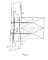
- FIG. 7 detail B of Figure 4 is shown in which the connection of the rainscreen arrangement to a stud 5 is shown.
- a screw or similar fastener 32 connects screens 10 and 20 and a batten 14 securely to the stud.
- FIG 8 a vertical joint between horizontally adjacent panels of the screen arrangement is illustrated.
- a sealing strip 34 which is preferably 50 mm wide and constructed from a resilient material such as an appropriate plastics or rubber material is laid over the joint between the adjacent air barrier panels 10.
- the sealing strip 34 is preferably coated with an adhesive on either side to assist with location under attention about the joint.
- the battens 14 (which may alternatively comprise a single batten if desired) are provided directly over an upper surface of the sealing strip 34 so that one side of each batten holds the sealing strip securely in place.
- a further sealing strip 36 is provided having a base 38 and two projecting sealing lips 40 projecting from the base.
- One lip 40 engages with the rear surface of each of the rainscreen panels 20. The arrangement is such that a substantial seal is made between the side edges of each of the panels 10 and 20.
- a flashing 42 which has a first edge part 44 and a second edge part 46 for location on an air barrier panel and on an external surface of a rainscreen panel respectively.
- a central bridging portion 48 is angled at 90 degrees or more i.e. substantially obtusely to the edges 44 and 46. This provides a downwardly angled flow path, which allows any water within the spaces of the upper panels as shown in Figure 9 to drain out from between those panels and on to the exterior of the lower rainscreen panel shown in the figure.
- the flashing 42 also assists with sealing or at least protecting the seal between the lower air barrier panel and lower rainscreen panel.
- a seal created by sealant 48 over a backing PEF rod 50 for sealing vertically adjacent air barrier panels is also shown.
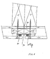
- FIG 11 which shows detail F of Figure 4 , a joint between vertically adjacent panels as shown a short support batten 16 is used together with an aluminium socket 54 which screws 56 penetrate.
- a sealant 58 such as that sold under the trademark Fosrock MS sealant or similar is used between socket 54 and the edges of rainscreen panels 20.
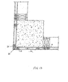
- FIG 13 an external corner detail is shown in which it can be seen that a sealing strip 60, for example an 80 mm wide strip of substantially resilient material such as butynol is provided.
- a sealing strip 60 for example an 80 mm wide strip of substantially resilient material such as butynol is provided.
- Figure 14 detail I of Figure 5 is shown in which it can be seen that a sealing strip the same as or similar to that described above with reference to Figure 13 may also be used to provide an appropriate seal at an internal corner.
- the outer surface, i.e. the surface away from the framing, of the air barrier panels 10 is preferably coated with a substantially water resistant coating.
- the exterior surface, i.e. the surface opposite battens 14 of rainscreen panels 20 is also preferably coated with a substantially water resistant coating.
- an effective rainscreen system particularly a pressure-equalised rainscreen, together with an effective sealing arrangement.
- the sealing arrangement allows the spaces between air barrier and rainscreen panels to be effectively sealed along the side and upper edges while providing a vent at the lower edge.
- air pressure within the spaces is equalised with exterior pressure such as that from wind for example. Therefore, there is no pressure differential to force water such as raindrops carried by wind to enter the spaces behind the rainscreen. As a result, the rainscreen prevents rain from entering the building structure.
Landscapes
- Engineering & Computer Science (AREA)
- Architecture (AREA)
- Civil Engineering (AREA)
- Structural Engineering (AREA)
- Physics & Mathematics (AREA)
- Electromagnetism (AREA)
- Building Environments (AREA)
- Finishing Walls (AREA)
- Transition And Organic Metals Composition Catalysts For Addition Polymerization (AREA)
- Ventilation (AREA)
Abstract
Description
- This invention relates to exterior cladding systems for both residential and commercial buildings and in particular a rainscreen apparatus, system and methods of manufacture and assembly.
- The invention is directed particularly, but not solely to a rainscreen system having a means of pressure equalization with the external environment.
- Any discussion of the prior art throughout the specification is provided so that the invention and the advantages of it may be better understood in an appropriate technical context, but should in no way be considered as an admission that such prior art is widely known or forms part of common general knowledge in the field.
- Generally, when applying cladding or a rainscreen to a building frame, an air barrier layer is first placed upon the frame. A series of battens are then placed atop the air barrier and attached to the frame underneath. Finally, a cladding material is typically fixed to the battens. The space behind the cladding is usually configured to allow ventilation and removal of any water that may enter the wall cavity. Water trapped in a wall cavity if allowed to remain or accumulate, can affect the durability of frame and cladding components.
- In known cladding or rainscreen systems, a waterproof membrane such as housewrap, sarking or building paper is the sole air barrier placed upon the building frame, see
US 6 233 690 B1 Entry of water, particularly wind driven rain, into buildings can be a problem when such systems are used in high wind areas or on the upper stories of low to medium rise buildings. This is because housewraps, sarking materials and the like are flexible and may deform when exposed to wind or more generally when a pressure differential exists on opposite sides of the air barrier; allowing rain or liquid water to enter the wall behind the air barrier, particularly where adjacent sheets of sarking join or overlap, and thereby become trapped within the wall framing with little hope of removal. - What is needed is a cladding or rainscreen system for buildings that will better protect the building frame from water ingress during periods of wind driven rain.
- It is an object of the present invention to overcome or substantially ameliorate one or more of the disadvantages of the prior art, or at least to provide a useful alternative.
- It is a further obj ect of the invention in its preferred form to provide an improved rainscreen system and method that are less susceptible to the ingress of water during periods of wind driven rain.
- It is a further object of the invention in its preferred form to provide an air barrier for a wall cladding system that is suitable for use on low to mid-rise buildings.
- In one aspect, the invention broadly provides a rainscreen apparatus including:
- a substantially rigid air barrier adapted for attachment to a building structure;
- a rainscreen panel adapted for attachment over the air barrier;
- a spacing member adapted to provide a clearance space between the air barrier and the rainscreen panel; and
- sealing means adapted to provide substantial pressure equalisation between the clearance space and the external atmosphere.
- Preferably, the rainscreen apparatus includes an air vent to atmosphere from the pressure equalised space to allow air pressure within the space to equalise with air pressure externally of the space. Preferably, the clearance space is sealed by the sealing means on the top and sides, and vented at the bottom, to prevent ingress wind forced rain.
- Preferably, the rainscreen apparatus is suitable for use on building frames with studs placed at predetermined intervals so as to resist water ingress with wind pressure at up to a predetermined level. More preferably, the stud placement is between approximately 400 and 610 mm center to center. The predetermined wind pressure is preferably greater than approximately 1 kPa and less than approximately 4.5 kPa.
- The substantially rigid air barrier may be comprised of any polymeric or cellulosic or cementitous material suitably reinforced to provide the degree of rigidity required to resist water ingress when incorporated into a rainscreen apparatus and exposed to a predetermined wind pressure according to a standardized wind test.
- In one preferred embodiment, the rigid air barrier is in the form of a panel. Preferably, the air barrier panel is between 2mm and around 15mm in thickness, and more preferably 5mm-7mm thick. More preferably, the air barrier is a panel comprising oriented strandboard, plywood, metal or expanded polymeric foam, or a combination of these materials. Most preferably, the panel comprises fibre cement.
- In one preferred embodiment, the air barrier is a panel that substantially prevents liquid water from passing therethrough by attachment of a sheet of polymeric or substantially water repellent cellulosic material to the exterior surface of the panel. Alternatively, the air barrier is a panel having at least the exterior side treated with a material that repels liquid water. Alternatively, the air barrier is panel that contains a water repellent material.
- In another embodiment, the rigid air barrier is in the form of at least one thin sheet comprising a polymeric or substantially water repellent cellulosic material, the sheet having relatively rigid reinforcing means attached thereto. In one embodiment, the thin sheet is a substantially polyolefinic material having relatively rigid reinforcing means comprising a mesh of fibreglass, metal or polymeric material laminated to at least one surface of the thin sheet. Alternatively, the relatively rigid reinforcing means may include a series of battens or the like laminated to at least one surface of the thin sheet.
- The rainscreen may be of any exterior cladding known in the art. Preferably the rainscreen is in the form of a panel comprising a cementitous material, oriented strandboard, plywood, metal, polymeric foam or a combination of these. More preferably the rainscreen panel may be between approximately 2mm-1 lmm thick, more preferably 7-1 lmm thick, and most preferably around 9mm thick. Preferably, the rainscreen panel comprises fibre cement sheet.
- In certain embodiments, the rainscreen apparatus includes a seal for sealing a joint between at least two adjacent air barrier panel, the seal including a sealing strip of a substantially resilient material having a first surface and a second surface opposite to the first surface, the first surface being adapted to contact the panels, and at least one batten provided in use over the second surface of the sealing strip, the batten being in contact with the second surface so as to maintain the first surface of the strip in contact with the region of the air barrier adjacent to the joint.
- Preferably, the first surface has an adhesive provided thereon. Preferably the second surface has an adhesive provided thereon.
- In some embodiments, the rainscreen apparatus has a flashing including a first edge portion adapted to be located on or adjacent to a lower edge of an air barrier, a second edge portion adapted to be located on or adjacent to an upper region of a rainscreen panel provided below the air barrier panel, and a central portion which is contiguous with the first and second edge portions and is provided at a substantially obtuse angle to the first and second edge portions.
- Preferably, the central portion slopes downwardly to allow water to drain over the central portion and exterior to the rainscreen panel.
- In certain embodiments, , the vent includes a first wall adapted for location on or adjacent to the air barrier panel, a second wall adapted to be located on or adjacent to an internal surface of the rainscreen panel, and a central portion connected between the first and second walls, the central portion having one or more apertures therein, the one or more apertures allowing liquid to drain from the space and also allowing ingress of air into the space.
- In some preferred embodiments the rainscreen apparatus includes a sealing member having a base and at least two lips projecting from the base, the lips being spaced from each other, one lip being adapted to make a substantially sealing contact with a rear surface of a first rainscreen panel, and the second lip being adapted to make a substantially sealing contact with the rear surface of a second rainscreen panel, the second panel being located adjacent to the first panel.
- In a further aspect, the invention broadly provides a method of constructing a rainscreen, the method including the steps of attaching a substantially rigid air barrier to an external side of a building frame, attaching one or more battens over an exterior surface of the substantially rigid air barrier, and attaching a rainscreen panel over at least one of the battens.
- Preferably, the substantially rigid air barrier is in the form of a panel. Preferably the panel is between approximately 2-15mm thick, and more preferably 5mm-7mm thick. The air barrier may be formed from any suitable material including cementitious material, oriented strandboard, plywood, metal, expanded polymeric foam or a combination of these. Most preferably, the panel is formed from fibre cement.
- Preferably, the rainscreen is in the form of a panel comprising a cementitous material, oriented strandboard, plywood, metal, polymeric foam or a combination of these. More preferably the rainscreen panel may be between approximately 2mm-1 lmm thick, more preferably 7-1 lmm thick, most preferably 9mm thick. Most preferably, the rainscreen panel comprises fibre cement. In a further aspect, the invention broadly provides a method for constructing a rainscreen, said method including the steps of:
- providing a substantially rigid air barrier panel;
- coating the panel with a water resistant material;
- attaching one or more battens over an exterior surface of the air barrier panel;
- fixing a rainscreen panel over the battens so that the rainscreen panel is spaced from the air barrier panel; and
- coating the exterior surface of the rainscreen panel with a substantially water resistant material.
- Preferably, one or both of the panels may be fibre reinforced cement panels.
- Preferred embodiments of the invention will be described, with reference to the accompanying drawings, in which:
-
Figure 1 is a front elevation of a two storey building structure; -
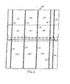
Figure 2 is a front elevation of the structure ofFigure 1 including an air barrier affixed thereto; -
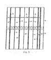
Figure 3 is an elevation ofFigure 2 further including battens provided over the air barrier; -
Figure 4 is a front elevation of the structure ofFigure 3 and further including a rainscreen provided over the battens; -
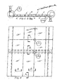
Figure 5 is a plan view ofFigure 4 ; -
Figure 6 is a side elevation and cross section of detail of A ofFigure 4 ; -
Figure 6A is an isometric sketch of a vent; -
Figure 7 is a plan view and cross section of detail B ofFigure 4 ; -
Figure 8 is a plan view and cross section of detail C ofFigure 4 ; -
Figure 9 is a side elevation and cross section of detail D ofFigure 4 ; -
Figure 10 is a partial elevation ofFigure 4 showing detail E; -
Figure 11 is a side elevation and cross section showing detail F ofFigure 4 ; -
Figure 12 is a partial elevation ofFigure 4 showing detail G; -
Figure 13 is a sectional plan view showing detail H ofFigure 5 ; and -
Figure 14 is a plan view and cross section showing detail I ofFigure 5 . -
Figure 1 shows a building structure, having structural concrete supports in the form ofconcrete columns 1 and a suspended concrete floor 2. Between the concrete structural supports, the framing generally referenced 4 is provided includingstuds 5 andnogs 6. In this example, the framing is timber but those skilled in the art will appreciate that other framing materials may be used, for example steel frame materials. The structure inFigure 1 represents an exposed exterior structure of a building, preferably but not necessarily a commercial building. - Turning to
Figure 2 , the first step in cladding the framing so as to provide a rainscreen according to the invention is illustrated in which an air barrier generally referenced 8 is provided. In the example illustrated, a number of separate panels are affixed to the framing in order to create the air barrier. The number of panels may vary, for example a single panel could be used and the number of panels will vary depending upon the dimensions of the panels that are used and the area of the structure required to be covered. InFigure 2 ,12 air barrier panels, each referenced 10 are shown. The panels are preferably fibre cement panels (for example Hardiflex® manfufactured by James Hardie Building Products Pty. Ltd). However, panels of wood, wood composite (such as oriented strandboard or plywood), metal, expanded polymeric foam or composite panels comprising these materials will also make suitable rigid air barrier. At the vertical joints betweenair barrier panels 10, a sealingstrip 12 is provided as will be described in more detail below. - Alternatively, the rigid air barrier is in the form of at least one thin sheet comprising a polymeric or substantially water repellent cellulosic material, said sheet having a relatively rigid reinforcing means attached thereto. In one embodiment, the thin sheet is a substantially polyolefin material having a relatively rigid reinforcing means comprising a mesh of fibreglass, metal or polymeric material laminated to at least one surface of the thin sheet. Alternatively, the relatively rigid reinforcing means is a series of battens or the like laminated to at least one surface of the thin sheet.
- In
Figure 3 , spacers in the form ofbattens 14 are shown placed over the air barrier. In this example, the battens are preferably constructed from a treated timber material and are preferably 50 mm x 20 mm in cross section. Those skilled in the art will appreciate that other materials may be used to provide spacers, for example comprised of metal or polymeric composite Further battens orspacers 16 may also be provided if necessary. - In
Figure 4 , the structure ofFigure 3 is shown withrain barrier panels 20 affixed over the battens so that there are a number of spaces provided between the rainscreen wall and the air barrier.Figure 5 shows the partial structure in plan view in which spaces between the air barrier and rainscreen panels are referenced 21. InFigures 4 and 5 , the regions labelled A-H are shown in greater detail than the remaining figures. - Detail A is shown in
Figure 6 from which it can be seen that theair barrier panel 10 is affixed at its lower edge by a fastener such asnail 22 to thebottom plate 24 of the framing assembly. An appropriate screw such as a 65 mm x 10gwood thread screw 26 affixes the rainscreen panel, the batten and the air barrier panel to the bottom plate. Thenail 22 may also hold avent strip 28 in location at the base of the screen. Therain barrier panel 20 preferably comprises a fibre reinforced cement panel such as that marketed under the trademark Titan™ or Exotec™. The preferred thickness ofpanel 20 is 7 - 11 mm, most preferably 9 mm. InFigure 6A the vent strip is shown in greater detail as an isometric sketch which reveals it has a number ofapertures 30 in the base which have sufficient dimension to allow any water such as rain water in the space between thepanels - Turning to
Figure 7 , detail B ofFigure 4 is shown in which the connection of the rainscreen arrangement to astud 5 is shown. A screw orsimilar fastener 32 connectsscreens - In
Figure 8 , a vertical joint between horizontally adjacent panels of the screen arrangement is illustrated. A sealing strip 34, which is preferably 50 mm wide and constructed from a resilient material such as an appropriate plastics or rubber material is laid over the joint between the adjacentair barrier panels 10. The sealing strip 34 is preferably coated with an adhesive on either side to assist with location under attention about the joint. The battens 14 (which may alternatively comprise a single batten if desired) are provided directly over an upper surface of the sealing strip 34 so that one side of each batten holds the sealing strip securely in place. - On the other side of the
battens 14, a further sealingstrip 36 is provided having a base 38 and two projecting sealinglips 40 projecting from the base. Onelip 40 engages with the rear surface of each of therainscreen panels 20. The arrangement is such that a substantial seal is made between the side edges of each of thepanels - Turning to
Figure 9 , detail D ofFigure 4 is shown. In this figure, it can be seen that a flashing 42 is provided which has afirst edge part 44 and asecond edge part 46 for location on an air barrier panel and on an external surface of a rainscreen panel respectively. Acentral bridging portion 48 is angled at 90 degrees or more i.e. substantially obtusely to theedges Figure 9 to drain out from between those panels and on to the exterior of the lower rainscreen panel shown in the figure. As well as allowing drainage, the flashing 42 also assists with sealing or at least protecting the seal between the lower air barrier panel and lower rainscreen panel. A seal created bysealant 48 over a backingPEF rod 50 for sealing vertically adjacent air barrier panels is also shown. - In
Figure 10 , detail E ofFigure 4 is shown which again shows theseal strip 36 described above. - In
Figure 11 , which shows detail F ofFigure 4 , a joint between vertically adjacent panels as shown a short support batten 16 is used together with analuminium socket 54 which screws 56 penetrate. Asealant 58 such as that sold under the trademark Fosrock MS sealant or similar is used betweensocket 54 and the edges ofrainscreen panels 20. - In
Figure 12 , the aluminium socket and sealant arrangement is shown in elevation in accordance with detail G ofFigure 4 . - In
Figure 13 , an external corner detail is shown in which it can be seen that a sealingstrip 60, for example an 80 mm wide strip of substantially resilient material such as butynol is provided. InFigure 14 , detail I ofFigure 5 is shown in which it can be seen that a sealing strip the same as or similar to that described above with reference toFigure 13 may also be used to provide an appropriate seal at an internal corner. - The outer surface, i.e. the surface away from the framing, of the
air barrier panels 10 is preferably coated with a substantially water resistant coating. Similarly, the exterior surface, i.e. the surface opposite battens 14 ofrainscreen panels 20 is also preferably coated with a substantially water resistant coating. - From the foregoing it can be seen that an effective rainscreen system, particularly a pressure-equalised rainscreen, together with an effective sealing arrangement is provided. The sealing arrangement allows the spaces between air barrier and rainscreen panels to be effectively sealed along the side and upper edges while providing a vent at the lower edge. In this way, air pressure within the spaces is equalised with exterior pressure such as that from wind for example. Therefore, there is no pressure differential to force water such as raindrops carried by wind to enter the spaces behind the rainscreen. As a result, the rainscreen prevents rain from entering the building structure.
- Where in the foregoing description, reference has been made to specific components or integers of the invention having known equivalents then such equivalents are herein incorporated as if individually set forth.
- Although this invention has been described by way of example and with reference to possible embodiments thereof, it is to be understood that modifications or improvements may be made thereto without departing from the scope or spirit of the invention.
- It should be noted that various changes and modifications to the presently preferred embodiments described herein will be apparent to those skilled in the art. Such changes and modifications may be made without departing from the scope of the present invention and without diminishing its attendant advantages.
Claims (43)
- A rainscreen apparatus including:a substantially rigid air barrier adapted for attachment to a building structure;a rainscreen panel adapted for attachment over the air barrier;a spacing member adapted to provide a clearance space between the air barrier and the rainscreen panel; andsealing means adapted to provide substantial pressure equalisation within the clearance space.
- A rainscreen apparatus according to claim 1 including an air vent to atmosphere from said pressure equalised space to allow air pressure within said space to equalise with air pressure externally of said space.
- A rainscreen apparatus according to claim 1 or claim 2 wherein said apparatus is suitable for use on building frames with studs placed at a predetermined interval such that said apparatus resists water ingress under predetermined wind pressure.
- A rainscreen apparatus according to claim 3 wherein said studs are placed at between approximately 400 and 610 mm centre to centre and said predetermined wind pressure is greater than approximately 1 kPa and less than approximately 4. 5 kPa.
- A rainscreen apparatus according to any one of the preceding claims wherein said rigid air barrier is comprised of any polymeric or cellulosic or cementitous material suitably reinforced to provide the degree of rigidity required to resist water ingress when incorporated into said rainscreen apparatus and exposed to a predetermined wind pressure according to a standardized wind test.
- A rainscreen apparatus according to any one of the preceding claims wherein said rigid air barrier is in the form of a panel.
- A rainscreen apparatus according to claim 6 wherein said air barrier panel is between approximately 2-15mm thick.
- A rainscreen apparatus according to claim 6 or claim 7 wherein said air barrier panel is between 5-7mm thick.
- A rainscreen apparatus according to any one of claims 6 to 8 wherein said air barrier panel includes fibre cement, oriented strandboard, plywood, metal, expanded polymeric foam or a combination of these.
- A rainscreen apparatus according to any one of claims 6 to 9 wherein said air barrier panel is substantially formed from fibre cement.
- A rainscreen apparatus according to any one of claims 6 to 10 wherein said panel includes a sheet of polymeric or substantially water repellent cellulosic material attached to the exterior surface of the panel so as substantially to prevent water from passing therethrough.
- A rainscreen apparatus according to any one of claims 6 to 10 wherein said air barrier panel has at least the exterior side treated with a material that repels water.
- A rainscreen apparatus according to any one of claims 6 to 10 wherein said air barrier panel includes a water repellent material.
- A rainscreen apparatus according to any one of claims 1 to 5 wherein said rigid air barrier is in the form of at least one thin sheet comprising a polymeric or substantially water repellent cellulosic material, said sheet having a relatively rigid reinforcing means attached thereto.
- A rainscreen apparatus according to claim 14 wherein said sheet includes a polyolefin material having a relatively rigid reinforcing means including a mesh of fibreglass, metal or polymeric material laminated to at least one surface of said sheet.
- A rainscreen apparatus according to claim 14 wherein said sheet includes a polyolefin material having a relatively rigid reinforcing means including a series of battens or the like laminated to at least one surface of said sheet.
- A rainscreen apparatus according to any one of the preceding claims wherein said rainscreen panel includes a cementitous material, oriented strandboard, plywood, metal, polymeric foam or a combination of these.
- A rainscreen apparatus according to any one of the preceding claims wherein said rainscreen panel is between approximately 2-11 mm thick.
- A rainscreen apparatus according to any one of the preceding claims wherein said rainscreen panel is between approximately 7-11 mm thick.
- A rainscreen apparatus according to any one of the preceding claims wherein said rainscreen panel is around 9mm thick.
- A rainscreen apparatus according to any one of the preceding claims wherein said rainscreen panel is substantially formed from fibre cement.
- A rainscreen apparatus according to any one of the claims 1 to 16 wherein said rainscreen panel is formed from an exterior cladding material.
- A rainscreen air apparatus according to any one of claims 1 to 22, including a seal for sealing a joint between at least two adjacent rigid air barriers, said seal including a sealing strip of a substantially resilient material having a first surface and a second surface opposite to said first surface, said first surface being adapted to contact said rigid air barriers, and at least one batten provided in use over said second surface of the seal strip, said batten being in contact with the second surface so as to maintain said first surface of the strip in contact with the region of said air barrier adjacent to said joint.
- A rainscreen apparatus according to claim 23 wherein said first surface has an adhesive provided thereon.
- A rainscreen apparatus according to claim 23 or claim 24 wherein said second surface has an adhesive provided thereon.
- A rainscreen apparatus according to any one of the claims 1 to 25 having a flashing, said flashing including a first edge portion adapted to be located on or adjacent to a lower edge of said air barrier, a second edge portion adapted to be located on or adjacent to an upper region of said rainscreen panel provided below said air barrier, and a central portion which is contiguous with said first and second edge portions and is provided at a substantially obtuse angle to said first and second edge portions.
- A rainscreen apparatus according to claim 26 wherein said central portion slopes downwardly to allow water to drain over said central portion and exterior to said rainscreen panel.
- A rainscreen apparatus according to claim 2 or any one of claims 3 to 27 when dependent on claim 2, wherein said air vent includes a first wall adapted for location on or adjacent to said air barrier, a second wall adapted to be located on or adjacent to an internal surface of said rainscreen panel, and a central portion connected between said first and second walls, said central portion having one or more apertures therein allowing liquid to drain from said space and also allowing ingress of air into said space.
- A rainscreen apparatus according to any one of claims 1 to 28, including a sealing member having a base and at least two lips projecting from said base, said lips being spaced from each other, one lip being adapted to make a substantially sealing contact with a rear surface of a first rainscreen panel, and the second lip being adapted to make a substantially sealing contact with the rear surface of a second rainscreen panel, said second panel being located adjacent to the first panel.
- A method of constructing a rainscreen apparatus according to any one of claims 1 to 29, the method including the steps of:attaching said rigid air barrier to an external side of building framing;attaching one or more battens over an exterior surface of said rigid air barrier; andattaching said rainscreen panel over at least one of said battens.
- A method of constructing a rainscreen apparatus according to claim 30 wherein said rigid air barrier is in the form of a panel.
- A method of constructing a rainscreen apparatus according to claim 31 wherein said air barrier panel is between approximately 2-15mm thick.
- A method of constructing a rainscreen apparatus according to claim 31 or claim 32 wherein said air barrier panel is between approximately 5-7mm thick.
- method of constructing a rainscreen apparatus according to any one of claims 31 to 33 wherein said air barrier panel includes fibre cement, oriented strandboard, plywood, metal, expanded polymeric foam or a combination of these.
- A method of constructing a rainscreen apparatus according to any one of claims 31 to 34 wherein said air barrier panel is substantially formed from fibre cement.
- A method of constructing the rainscreen apparatus according to any one of claims 30 to 35 wherein said rainscreen panel includes a cementitous material, oriented strandboard, plywood, metal, polymeric foam or a combination of these.
- A method of constructing a rainscreen apparatus according to any one of claims 30 to 36 wherein said rainscreen panel is between approximately 2-11 mm thick.
- A method of constructing a rainscreen apparatus according to any one of claims 30 to 37 wherein said rainscreen panel is between approximately 7-11 mm thick.
- A method of constructing a rainscreen apparatus according to any one of claims 30 to 38 wherein said rainscreen panel is substantially 9mm thick.
- A method of constructing a rainscreen apparatus according to any one of claims 30 to 39 wherein said rainscreen panel is substantially formed from fibre cement.
- A method of constructing a rainscreen apparatus according to claims 30 to 40 including the step of:coating said air barrier with a water resistant material.
- A method of constructing a rainscreen apparatus according to any one of claims 30 to 41 including the step of:coating the exterior surface of said rainscreen panel with a substantially water resistant material.
- A method of constructing a rainscreen apparatus according to claim 41 or claim 42 wherein one or both of said rigid air barrier or said rainscreen panel is substantially formed from fibre reinforced cement.
Applications Claiming Priority (2)
| Application Number | Priority Date | Filing Date | Title |
|---|---|---|---|
| AU2003903440A AU2003903440A0 (en) | 2003-07-04 | 2003-07-04 | Rainscreen apparatus and method |
| PCT/IB2004/002202 WO2005003478A1 (en) | 2003-07-04 | 2004-07-05 | Rainscreen apparatus and method |
Publications (3)
| Publication Number | Publication Date |
|---|---|
| EP1660733A1 EP1660733A1 (en) | 2006-05-31 |
| EP1660733A4 EP1660733A4 (en) | 2008-07-02 |
| EP1660733B1 true EP1660733B1 (en) | 2011-06-08 |
Family
ID=31983074
Family Applications (1)
| Application Number | Title | Priority Date | Filing Date |
|---|---|---|---|
| EP04743866A Expired - Lifetime EP1660733B1 (en) | 2003-07-04 | 2004-07-05 | Rainscreen apparatus and method |
Country Status (11)
| Country | Link |
|---|---|
| US (1) | US8484921B2 (en) |
| EP (1) | EP1660733B1 (en) |
| JP (1) | JP4861171B2 (en) |
| KR (1) | KR20060052776A (en) |
| CN (1) | CN1816668B (en) |
| AT (1) | ATE512260T1 (en) |
| AU (1) | AU2003903440A0 (en) |
| CA (1) | CA2530334C (en) |
| NO (1) | NO20060364L (en) |
| NZ (1) | NZ544286A (en) |
| WO (1) | WO2005003478A1 (en) |
Families Citing this family (18)
| Publication number | Priority date | Publication date | Assignee | Title |
|---|---|---|---|---|
| US6689451B1 (en) | 1999-11-19 | 2004-02-10 | James Hardie Research Pty Limited | Pre-finished and durable building material |
| MXPA03009029A (en) | 2001-04-03 | 2004-02-12 | James Hardie Res Pty Ltd | Spline for siding planks, methods of making and installing. |
| MXPA05003691A (en) | 2002-10-07 | 2005-11-17 | James Hardie Int Finance Bv | Durable medium-density fibre cement composite. |
| US7998571B2 (en) | 2004-07-09 | 2011-08-16 | James Hardie Technology Limited | Composite cement article incorporating a powder coating and methods of making same |
| MX2008003173A (en) * | 2005-09-06 | 2008-03-18 | Smithkline Beecham Corp | Benzimidazole thiophene compounds as plk inhibitors. |
| US8689509B2 (en) | 2006-02-03 | 2014-04-08 | James Hardie Technology Limited | Expressed joint facade system |
| WO2007115379A1 (en) | 2006-04-12 | 2007-10-18 | James Hardie International Finance B.V. | A surface sealed reinforced building element |
| WO2008106735A1 (en) | 2007-03-08 | 2008-09-12 | James Hardie International Finance B.V. | Building system |
| NZ579719A (en) | 2007-03-21 | 2012-08-31 | Hardie James Technology Ltd | Drainage panel for a framed wall construction with a water resistant surface and drainage channels |
| CA2615154C (en) * | 2007-11-20 | 2012-06-19 | Bcm Developments Ltd. | Method of building construction |
| AU320072S (en) | 2008-03-07 | 2008-06-30 | Hardie James Technology Ltd | Building element |
| AU320071S (en) | 2008-03-07 | 2008-06-30 | Hardie James Technology Ltd | Building element |
| AU326889S (en) | 2009-05-29 | 2009-07-27 | Hardie James Technology Ltd | Building element |
| FR2950640A1 (en) * | 2009-09-29 | 2011-04-01 | Elmere | METHOD FOR PRODUCING A PREFABRICATED WOOD-BASED BUILDING BUILDING AND BUILDING THUS OBTAINED |
| ES2657612T3 (en) | 2010-05-28 | 2018-03-06 | The Diller Corporation | Laminate coating system for construction |
| US8875461B2 (en) | 2012-03-09 | 2014-11-04 | Wesley F. Kestermont | Foundation wall system |
| CN110344529B (en) * | 2019-07-26 | 2020-11-13 | 易县易新装配式建筑科技有限公司 | Assembled coincide floor |
| WO2024119003A1 (en) * | 2022-12-01 | 2024-06-06 | Advanced Architectural Products, Llc | Wall sill assembly and wall construction having a wall sill assembly |
Family Cites Families (31)
| Publication number | Priority date | Publication date | Assignee | Title |
|---|---|---|---|---|
| US2645824A (en) * | 1949-09-13 | 1953-07-21 | Edwin J Titsworth | Ventilated wall |
| US2724465A (en) * | 1950-02-04 | 1955-11-22 | Republic Steel Corp | Panel and curtain wall construction |
| US3568391A (en) * | 1968-10-30 | 1971-03-09 | United States Gypsum Co | Casing bead for use in a joint construction |
| US3760544A (en) * | 1971-05-27 | 1973-09-25 | Tetra Plastics | Sealing gasket with elongated internal stiffner |
| US3998016A (en) * | 1975-03-13 | 1976-12-21 | H. H. Robertson Company | Blow-in/blow-out wall structure |
| SE403640B (en) * | 1976-06-24 | 1978-08-28 | Thoren Torgny | BUILDING ELEMENT |
| US4286420A (en) * | 1979-04-18 | 1981-09-01 | Pharmakidis Panayiotis D | Heat retention wall system |
| US4655018A (en) * | 1985-01-31 | 1987-04-07 | National Concrete Masonry Association | Roof paver element and system |
| CH674391A5 (en) * | 1986-12-23 | 1990-05-31 | Sarna Granol Ag | |
| CA1298454C (en) | 1987-05-01 | 1992-04-07 | Franklin Roman Babienko | Curtain wall assembly |
| US4765107A (en) * | 1987-10-19 | 1988-08-23 | Ting Raymond M L | Vertical joint sealing of horizontal wall panels |
| FR2628775B1 (en) * | 1988-03-21 | 1991-05-03 | Gtm Batimen Travaux Publ | INTERMEDIATE VACUUM BUILDING FACADE WALL UNINTERRUPTED BETWEEN FLOORS AND ECONOMIC CONSTRUCTION METHOD |
| US5027572A (en) * | 1989-08-17 | 1991-07-02 | W. R. Grace & Co.-Conn. | Moisture and vapor barrier in exterior insulation finish systems |
| US5230189A (en) * | 1992-04-02 | 1993-07-27 | Tom Sourlis | Mortar and debris collection device and system |
| GB9216029D0 (en) * | 1992-07-28 | 1992-09-09 | Sto Ind Canada Inc | Exterior insulation and finish system |
| CA2204044C (en) | 1993-01-28 | 1999-07-06 | Richard E. Kroll | Insulative wall cladding |
| US5761864A (en) * | 1994-08-31 | 1998-06-09 | Nonoshita; Tadamichi | Thermally insulated building and a building panel therefor |
| US5596851A (en) * | 1995-01-13 | 1997-01-28 | Ting; Raymond M. L. | Exterior wall perimeters |
| US5598671A (en) | 1995-02-09 | 1997-02-04 | Ting; Raymond M. L. | Externally drained wall joint |
| US5826388A (en) * | 1996-05-07 | 1998-10-27 | K2, Inc. | Composite insulating drainage wall system |
| CA2226595C (en) * | 1998-01-12 | 2003-12-02 | Emco Limited | Composite vapour barrier panel |
| US6233890B1 (en) * | 1999-02-24 | 2001-05-22 | United States Gypsum Company | Drainable sheathing membrane for exterior wall assembly water management system |
| JP2001260661A (en) * | 2000-03-23 | 2001-09-26 | Toyoda Gosei Co Ltd | Mounting structure of glass inner weather strip for automobile door |
| US6745531B1 (en) * | 2000-07-31 | 2004-06-08 | Construction Research & Technology Gmbh | Pressure equalized compartment for exterior insulation and finish system |
| US6619004B2 (en) * | 2000-09-14 | 2003-09-16 | William Loper | Water draining exterior wall structure |
| US6679010B2 (en) * | 2001-01-05 | 2004-01-20 | Nichiha Corporation | Overhanging member |
| GB2382827B (en) * | 2002-01-23 | 2003-11-12 | Thermal Economics Ltd | Improved thermal insulation |
| US6698144B1 (en) * | 2002-04-18 | 2004-03-02 | Plastic Components, Inc. | Stucco casing bead |
| US6918218B2 (en) * | 2002-06-04 | 2005-07-19 | Robert Greenway | External insulated finish system with high density polystyrene layer |
| WO2005103407A2 (en) * | 2004-04-19 | 2005-11-03 | Rotter Martin J | Rib vent system for roofing panels |
| WO2009006441A2 (en) * | 2007-06-28 | 2009-01-08 | Spiderlath, Inc. | Lath support system |
-
2003
- 2003-07-04 AU AU2003903440A patent/AU2003903440A0/en not_active Abandoned
-
2004
- 2004-07-05 KR KR1020067000212A patent/KR20060052776A/en not_active Withdrawn
- 2004-07-05 AT AT04743866T patent/ATE512260T1/en not_active IP Right Cessation
- 2004-07-05 NZ NZ544286A patent/NZ544286A/en not_active IP Right Cessation
- 2004-07-05 US US10/563,406 patent/US8484921B2/en active Active
- 2004-07-05 EP EP04743866A patent/EP1660733B1/en not_active Expired - Lifetime
- 2004-07-05 JP JP2006516594A patent/JP4861171B2/en not_active Expired - Fee Related
- 2004-07-05 CA CA2530334A patent/CA2530334C/en not_active Expired - Fee Related
- 2004-07-05 CN CN200480019066XA patent/CN1816668B/en not_active Expired - Fee Related
- 2004-07-05 WO PCT/IB2004/002202 patent/WO2005003478A1/en not_active Ceased
-
2006
- 2006-01-23 NO NO20060364A patent/NO20060364L/en not_active Application Discontinuation
Also Published As
| Publication number | Publication date |
|---|---|
| AU2003903440A0 (en) | 2003-07-17 |
| JP2007521427A (en) | 2007-08-02 |
| US20060156638A1 (en) | 2006-07-20 |
| NZ544286A (en) | 2007-09-28 |
| US8484921B2 (en) | 2013-07-16 |
| CA2530334C (en) | 2012-10-02 |
| EP1660733A1 (en) | 2006-05-31 |
| WO2005003478A1 (en) | 2005-01-13 |
| CA2530334A1 (en) | 2005-01-13 |
| CN1816668A (en) | 2006-08-09 |
| JP4861171B2 (en) | 2012-01-25 |
| CN1816668B (en) | 2010-04-28 |
| NO20060364L (en) | 2006-01-23 |
| KR20060052776A (en) | 2006-05-19 |
| EP1660733A4 (en) | 2008-07-02 |
| ATE512260T1 (en) | 2011-06-15 |
Similar Documents
| Publication | Publication Date | Title |
|---|---|---|
| CA2530334C (en) | Rainscreen apparatus and method | |
| US4869037A (en) | Wall construction | |
| US6591559B2 (en) | Exterior wall sealing system | |
| US10011990B2 (en) | Laminated air circulation board | |
| US6745531B1 (en) | Pressure equalized compartment for exterior insulation and finish system | |
| US10221562B2 (en) | Continuous wall assemblies and methods | |
| JP5483730B2 (en) | Frame structure and method | |
| US5836135A (en) | Drainage track | |
| US5826388A (en) | Composite insulating drainage wall system | |
| US6748709B1 (en) | Curtain wall support method and apparatus | |
| US5027572A (en) | Moisture and vapor barrier in exterior insulation finish systems | |
| US5937600A (en) | Exterior wall system and drip channel | |
| US20060236618A1 (en) | Pan flashing with sill wedge and window clip | |
| US12359423B2 (en) | Self-sealing joint sealing system | |
| US20180328026A1 (en) | Exterior insulation and finish wall drainage system | |
| JP5080191B2 (en) | Exterior wall construction structure | |
| US6952901B2 (en) | Panel mounted shingles assembly with ventilating screen | |
| AU2004254124B2 (en) | Rainscreen apparatus and method | |
| US12448780B2 (en) | Moisture porous building furring strip | |
| US20250020346A1 (en) | Self-adhering ventilation screed device | |
| US20240167271A1 (en) | Wall panel and method for constructing a wall | |
| JP2006045824A (en) | Building panel mounting structure | |
| JPH08144444A (en) | Interior / exterior structure | |
| HU217678B (en) | Covering element from laminated material to covering facades | |
| NZ719694B2 (en) | Wall cladding system |
Legal Events
| Date | Code | Title | Description |
|---|---|---|---|
| PUAI | Public reference made under article 153(3) epc to a published international application that has entered the european phase |
Free format text: ORIGINAL CODE: 0009012 |
|
| 17P | Request for examination filed |
Effective date: 20060203 |
|
| AK | Designated contracting states |
Kind code of ref document: A1 Designated state(s): AT BE BG CH CY CZ DE DK EE ES FI FR GB GR HU IE IT LI LU MC NL PL PT RO SE SI SK TR |
|
| DAX | Request for extension of the european patent (deleted) | ||
| A4 | Supplementary search report drawn up and despatched |
Effective date: 20080602 |
|
| 17Q | First examination report despatched |
Effective date: 20091203 |
|
| RAP1 | Party data changed (applicant data changed or rights of an application transferred) |
Owner name: JAMES HARDIE TECHNOLOGY LIMITED |
|
| GRAP | Despatch of communication of intention to grant a patent |
Free format text: ORIGINAL CODE: EPIDOSNIGR1 |
|
| GRAS | Grant fee paid |
Free format text: ORIGINAL CODE: EPIDOSNIGR3 |
|
| GRAA | (expected) grant |
Free format text: ORIGINAL CODE: 0009210 |
|
| AK | Designated contracting states |
Kind code of ref document: B1 Designated state(s): AT BE BG CH CY CZ DE DK EE ES FI FR GB GR HU IE IT LI LU MC NL PL PT RO SE SI SK TR |
|
| REG | Reference to a national code |
Ref country code: GB Ref legal event code: FG4D |
|
| REG | Reference to a national code |
Ref country code: CH Ref legal event code: EP |
|
| REG | Reference to a national code |
Ref country code: IE Ref legal event code: FG4D |
|
| REG | Reference to a national code |
Ref country code: DE Ref legal event code: R096 Ref document number: 602004032989 Country of ref document: DE Effective date: 20110721 |
|
| REG | Reference to a national code |
Ref country code: NL Ref legal event code: VDEP Effective date: 20110608 |
|
| PG25 | Lapsed in a contracting state [announced via postgrant information from national office to epo] |
Ref country code: SE Free format text: LAPSE BECAUSE OF FAILURE TO SUBMIT A TRANSLATION OF THE DESCRIPTION OR TO PAY THE FEE WITHIN THE PRESCRIBED TIME-LIMIT Effective date: 20110608 |
|
| PG25 | Lapsed in a contracting state [announced via postgrant information from national office to epo] |
Ref country code: FI Free format text: LAPSE BECAUSE OF FAILURE TO SUBMIT A TRANSLATION OF THE DESCRIPTION OR TO PAY THE FEE WITHIN THE PRESCRIBED TIME-LIMIT Effective date: 20110608 Ref country code: AT Free format text: LAPSE BECAUSE OF FAILURE TO SUBMIT A TRANSLATION OF THE DESCRIPTION OR TO PAY THE FEE WITHIN THE PRESCRIBED TIME-LIMIT Effective date: 20110608 Ref country code: ES Free format text: LAPSE BECAUSE OF FAILURE TO SUBMIT A TRANSLATION OF THE DESCRIPTION OR TO PAY THE FEE WITHIN THE PRESCRIBED TIME-LIMIT Effective date: 20110919 Ref country code: SI Free format text: LAPSE BECAUSE OF FAILURE TO SUBMIT A TRANSLATION OF THE DESCRIPTION OR TO PAY THE FEE WITHIN THE PRESCRIBED TIME-LIMIT Effective date: 20110608 Ref country code: GR Free format text: LAPSE BECAUSE OF FAILURE TO SUBMIT A TRANSLATION OF THE DESCRIPTION OR TO PAY THE FEE WITHIN THE PRESCRIBED TIME-LIMIT Effective date: 20110909 Ref country code: CY Free format text: LAPSE BECAUSE OF FAILURE TO SUBMIT A TRANSLATION OF THE DESCRIPTION OR TO PAY THE FEE WITHIN THE PRESCRIBED TIME-LIMIT Effective date: 20110608 |
|
| PG25 | Lapsed in a contracting state [announced via postgrant information from national office to epo] |
Ref country code: BE Free format text: LAPSE BECAUSE OF FAILURE TO SUBMIT A TRANSLATION OF THE DESCRIPTION OR TO PAY THE FEE WITHIN THE PRESCRIBED TIME-LIMIT Effective date: 20110608 Ref country code: NL Free format text: LAPSE BECAUSE OF FAILURE TO SUBMIT A TRANSLATION OF THE DESCRIPTION OR TO PAY THE FEE WITHIN THE PRESCRIBED TIME-LIMIT Effective date: 20110608 |
|
| PG25 | Lapsed in a contracting state [announced via postgrant information from national office to epo] |
Ref country code: PT Free format text: LAPSE BECAUSE OF FAILURE TO SUBMIT A TRANSLATION OF THE DESCRIPTION OR TO PAY THE FEE WITHIN THE PRESCRIBED TIME-LIMIT Effective date: 20111010 Ref country code: EE Free format text: LAPSE BECAUSE OF FAILURE TO SUBMIT A TRANSLATION OF THE DESCRIPTION OR TO PAY THE FEE WITHIN THE PRESCRIBED TIME-LIMIT Effective date: 20110608 Ref country code: CZ Free format text: LAPSE BECAUSE OF FAILURE TO SUBMIT A TRANSLATION OF THE DESCRIPTION OR TO PAY THE FEE WITHIN THE PRESCRIBED TIME-LIMIT Effective date: 20110608 |
|
| PG25 | Lapsed in a contracting state [announced via postgrant information from national office to epo] |
Ref country code: MC Free format text: LAPSE BECAUSE OF NON-PAYMENT OF DUE FEES Effective date: 20110731 Ref country code: PL Free format text: LAPSE BECAUSE OF FAILURE TO SUBMIT A TRANSLATION OF THE DESCRIPTION OR TO PAY THE FEE WITHIN THE PRESCRIBED TIME-LIMIT Effective date: 20110608 Ref country code: SK Free format text: LAPSE BECAUSE OF FAILURE TO SUBMIT A TRANSLATION OF THE DESCRIPTION OR TO PAY THE FEE WITHIN THE PRESCRIBED TIME-LIMIT Effective date: 20110608 Ref country code: RO Free format text: LAPSE BECAUSE OF FAILURE TO SUBMIT A TRANSLATION OF THE DESCRIPTION OR TO PAY THE FEE WITHIN THE PRESCRIBED TIME-LIMIT Effective date: 20110608 |
|
| REG | Reference to a national code |
Ref country code: CH Ref legal event code: PL |
|
| PLBE | No opposition filed within time limit |
Free format text: ORIGINAL CODE: 0009261 |
|
| STAA | Information on the status of an ep patent application or granted ep patent |
Free format text: STATUS: NO OPPOSITION FILED WITHIN TIME LIMIT |
|
| REG | Reference to a national code |
Ref country code: IE Ref legal event code: MM4A |
|
| PG25 | Lapsed in a contracting state [announced via postgrant information from national office to epo] |
Ref country code: LI Free format text: LAPSE BECAUSE OF NON-PAYMENT OF DUE FEES Effective date: 20110731 Ref country code: CH Free format text: LAPSE BECAUSE OF NON-PAYMENT OF DUE FEES Effective date: 20110731 |
|
| 26N | No opposition filed |
Effective date: 20120309 |
|
| PG25 | Lapsed in a contracting state [announced via postgrant information from national office to epo] |
Ref country code: IT Free format text: LAPSE BECAUSE OF FAILURE TO SUBMIT A TRANSLATION OF THE DESCRIPTION OR TO PAY THE FEE WITHIN THE PRESCRIBED TIME-LIMIT Effective date: 20110608 |
|
| PG25 | Lapsed in a contracting state [announced via postgrant information from national office to epo] |
Ref country code: DK Free format text: LAPSE BECAUSE OF FAILURE TO SUBMIT A TRANSLATION OF THE DESCRIPTION OR TO PAY THE FEE WITHIN THE PRESCRIBED TIME-LIMIT Effective date: 20110608 |
|
| REG | Reference to a national code |
Ref country code: DE Ref legal event code: R097 Ref document number: 602004032989 Country of ref document: DE Effective date: 20120309 |
|
| PG25 | Lapsed in a contracting state [announced via postgrant information from national office to epo] |
Ref country code: IE Free format text: LAPSE BECAUSE OF NON-PAYMENT OF DUE FEES Effective date: 20110705 |
|
| PG25 | Lapsed in a contracting state [announced via postgrant information from national office to epo] |
Ref country code: LU Free format text: LAPSE BECAUSE OF NON-PAYMENT OF DUE FEES Effective date: 20110705 |
|
| PG25 | Lapsed in a contracting state [announced via postgrant information from national office to epo] |
Ref country code: BG Free format text: LAPSE BECAUSE OF FAILURE TO SUBMIT A TRANSLATION OF THE DESCRIPTION OR TO PAY THE FEE WITHIN THE PRESCRIBED TIME-LIMIT Effective date: 20110908 |
|
| PG25 | Lapsed in a contracting state [announced via postgrant information from national office to epo] |
Ref country code: TR Free format text: LAPSE BECAUSE OF FAILURE TO SUBMIT A TRANSLATION OF THE DESCRIPTION OR TO PAY THE FEE WITHIN THE PRESCRIBED TIME-LIMIT Effective date: 20110608 |
|
| PG25 | Lapsed in a contracting state [announced via postgrant information from national office to epo] |
Ref country code: HU Free format text: LAPSE BECAUSE OF FAILURE TO SUBMIT A TRANSLATION OF THE DESCRIPTION OR TO PAY THE FEE WITHIN THE PRESCRIBED TIME-LIMIT Effective date: 20110608 |
|
| REG | Reference to a national code |
Ref country code: FR Ref legal event code: PLFP Year of fee payment: 12 |
|
| REG | Reference to a national code |
Ref country code: FR Ref legal event code: PLFP Year of fee payment: 13 |
|
| REG | Reference to a national code |
Ref country code: FR Ref legal event code: PLFP Year of fee payment: 14 |
|
| REG | Reference to a national code |
Ref country code: FR Ref legal event code: PLFP Year of fee payment: 15 |
|
| PGFP | Annual fee paid to national office [announced via postgrant information from national office to epo] |
Ref country code: FR Payment date: 20210611 Year of fee payment: 18 |
|
| PGFP | Annual fee paid to national office [announced via postgrant information from national office to epo] |
Ref country code: GB Payment date: 20210609 Year of fee payment: 18 |
|
| PGFP | Annual fee paid to national office [announced via postgrant information from national office to epo] |
Ref country code: DE Payment date: 20210608 Year of fee payment: 18 |
|
| REG | Reference to a national code |
Ref country code: DE Ref legal event code: R119 Ref document number: 602004032989 Country of ref document: DE |
|
| GBPC | Gb: european patent ceased through non-payment of renewal fee |
Effective date: 20220705 |
|
| PG25 | Lapsed in a contracting state [announced via postgrant information from national office to epo] |
Ref country code: FR Free format text: LAPSE BECAUSE OF NON-PAYMENT OF DUE FEES Effective date: 20220731 |
|
| PG25 | Lapsed in a contracting state [announced via postgrant information from national office to epo] |
Ref country code: GB Free format text: LAPSE BECAUSE OF NON-PAYMENT OF DUE FEES Effective date: 20220705 Ref country code: DE Free format text: LAPSE BECAUSE OF NON-PAYMENT OF DUE FEES Effective date: 20230201 |