EP1659699B1 - Mobile communication terminal and signal receiving method thereof - Google Patents
Mobile communication terminal and signal receiving method thereof Download PDFInfo
- Publication number
- EP1659699B1 EP1659699B1 EP05025465A EP05025465A EP1659699B1 EP 1659699 B1 EP1659699 B1 EP 1659699B1 EP 05025465 A EP05025465 A EP 05025465A EP 05025465 A EP05025465 A EP 05025465A EP 1659699 B1 EP1659699 B1 EP 1659699B1
- Authority
- EP
- European Patent Office
- Prior art keywords
- signal
- mobile broadcast
- cdma
- gps
- dmb
- Prior art date
- Legal status (The legal status is an assumption and is not a legal conclusion. Google has not performed a legal analysis and makes no representation as to the accuracy of the status listed.)
- Expired - Fee Related
Links
Images

Classifications
-
- H—ELECTRICITY
- H04—ELECTRIC COMMUNICATION TECHNIQUE
- H04W—WIRELESS COMMUNICATION NETWORKS
- H04W88/00—Devices specially adapted for wireless communication networks, e.g. terminals, base stations or access point devices
- H04W88/02—Terminal devices
- H04W88/06—Terminal devices adapted for operation in multiple networks or having at least two operational modes, e.g. multi-mode terminals
-
- H—ELECTRICITY
- H04—ELECTRIC COMMUNICATION TECHNIQUE
- H04B—TRANSMISSION
- H04B1/00—Details of transmission systems, not covered by a single one of groups H04B3/00 - H04B13/00; Details of transmission systems not characterised by the medium used for transmission
- H04B1/38—Transceivers, i.e. devices in which transmitter and receiver form a structural unit and in which at least one part is used for functions of transmitting and receiving
- H04B1/40—Circuits
- H04B1/403—Circuits using the same oscillator for generating both the transmitter frequency and the receiver local oscillator frequency
- H04B1/406—Circuits using the same oscillator for generating both the transmitter frequency and the receiver local oscillator frequency with more than one transmission mode, e.g. analog and digital modes
-
- H—ELECTRICITY
- H04—ELECTRIC COMMUNICATION TECHNIQUE
- H04B—TRANSMISSION
- H04B1/00—Details of transmission systems, not covered by a single one of groups H04B3/00 - H04B13/00; Details of transmission systems not characterised by the medium used for transmission
- H04B1/005—Details of transmission systems, not covered by a single one of groups H04B3/00 - H04B13/00; Details of transmission systems not characterised by the medium used for transmission adapting radio receivers, transmitters andtransceivers for operation on two or more bands, i.e. frequency ranges
- H04B1/0053—Details of transmission systems, not covered by a single one of groups H04B3/00 - H04B13/00; Details of transmission systems not characterised by the medium used for transmission adapting radio receivers, transmitters andtransceivers for operation on two or more bands, i.e. frequency ranges with common antenna for more than one band
- H04B1/0057—Details of transmission systems, not covered by a single one of groups H04B3/00 - H04B13/00; Details of transmission systems not characterised by the medium used for transmission adapting radio receivers, transmitters andtransceivers for operation on two or more bands, i.e. frequency ranges with common antenna for more than one band using diplexing or multiplexing filters for selecting the desired band
-
- H—ELECTRICITY
- H04—ELECTRIC COMMUNICATION TECHNIQUE
- H04B—TRANSMISSION
- H04B1/00—Details of transmission systems, not covered by a single one of groups H04B3/00 - H04B13/00; Details of transmission systems not characterised by the medium used for transmission
- H04B1/38—Transceivers, i.e. devices in which transmitter and receiver form a structural unit and in which at least one part is used for functions of transmitting and receiving
- H04B1/3805—Transceivers, i.e. devices in which transmitter and receiver form a structural unit and in which at least one part is used for functions of transmitting and receiving with built-in auxiliary receivers
-
- H—ELECTRICITY
- H04—ELECTRIC COMMUNICATION TECHNIQUE
- H04B—TRANSMISSION
- H04B7/00—Radio transmission systems, i.e. using radiation field
- H04B7/02—Diversity systems; Multi-antenna system, i.e. transmission or reception using multiple antennas
- H04B7/04—Diversity systems; Multi-antenna system, i.e. transmission or reception using multiple antennas using two or more spaced independent antennas
- H04B7/08—Diversity systems; Multi-antenna system, i.e. transmission or reception using multiple antennas using two or more spaced independent antennas at the receiving station
- H04B7/0802—Diversity systems; Multi-antenna system, i.e. transmission or reception using multiple antennas using two or more spaced independent antennas at the receiving station using antenna selection
- H04B7/0817—Diversity systems; Multi-antenna system, i.e. transmission or reception using multiple antennas using two or more spaced independent antennas at the receiving station using antenna selection with multiple receivers and antenna path selection
- H04B7/082—Diversity systems; Multi-antenna system, i.e. transmission or reception using multiple antennas using two or more spaced independent antennas at the receiving station using antenna selection with multiple receivers and antenna path selection selecting best antenna path
Definitions
- the present invention relates to a mobile communication terminal, and more particularly, to a mobile communication terminal and signal receiving method thereof.
- the present invention is suitable for a wide scope of applications, it is particularly suitable for receiving GPS and mobile broadcast signals by preventing interference between radio signals received via a dual band antenna.
- DMB European digital audio broadcasting
- DMB describes a broadcasting service that enables appreciation of high quality video and CD-level music at anytime or anywhere.
- DMB is merging with a current mobile communication technology such that DMB service will be available via a mobile communication terminal.
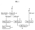
- FIG. 1 is a block diagram of a mobile communication terminal to receive CDMA and DMB signals according to a related art.
- a mobile communication terminal consists of a CDMA-DMB dual band antenna 11 and a DMB antenna 12 to provide CDMA communications and DMB services.
- Signals received via the CDMA-DMB dual antenna 11 are selectively switched by a diplexer 13 according to mode selection control signals, respectively.
- a CDMA signal is inputted to a radio frequency receiver (RFR) chipset 17 via a CDMA RF path 14, whereas a DMB signal is inputted to a DMB chipset 18 via a first DMB RF path 15.
- a DMB signal received via the DMB antenna 12 is inputted into the DMB chipset 18 via a second DMB RF path 16.
- the DMB chipset 18 selects, based on the path having the better radio sensitivity, which of the two DMB signals is to be used.
- the CDMA-DMB dual band antenna 11 is replaced by a CDMA-DMB-GPS triple band antenna to perform triple switching using an SP3T (single pole three-throw) switch and the like or a GPS antenna is independently provided to use.
- SP3T single pole three-throw
- a primary interference signal between a 1.57GHz GPS signal and an 824 ⁇ 896MHs CDMA signal lies on 2.39 ⁇ 2.47GHz to affect a 2.6GHz DMB satellite signal.
- a primary interference signal between the CDMA and DMB satellite signals lies on 1.78 ⁇ 1.70GHz to affect the 1.57GHz GPS signal.
- the three antennas coexisting in one mobile communication terminal mutually play a role as dipole intervening with each other in radio sensitivity to degrade the radio sensitivity or reception.
- WO 03/088510 A1 discloses a terminal capable of receiving data from a broadcast station and simultaneously participating in a wireless network via transmissions to a wireless station.
- the terminal includes a multi-band antenna for reception of signals from both the broadcast station and the base station.
- a diplexer filters the received signals so that broadcast signals are routed to a broadcast receiver and communication signals are routed to a network transceiver in the terminal.
- US 2002/003494 A1 discloses a combined GPS-DAB receiver having a single antenna and a mixer stage supplied with a local oscillator signal of tunable frequency.
- the receiver At the detection of any DAB-related signal, the receiver is functioning in a DAB reception mode and switches a controllable switching device to a digital DAB signal path including a DAB demodulator.
- an oscillator providing the local oscillator signal is tuned to a frequency suitable for DAB reception.
- the receiver is switched from the DAB reception mode into a GPS reception mode by switching the switching device to a GPS signal path. In the GPS reception mode, the oscillator provides an oscillator signal of a different frequency suitable for GPS reception.
- WO 2004/086657 A2 discloses a wireless terminal device comprising separate antennas for the reception of different types of services.
- a first service received via one of the antennas is a broadcasting service and a second service received via the other antenna is a position measuring service.
- the second service is a bidirectional communication service.
- the terminal device includes a common tuner unit coupled to the two antennas for frequency-converting the received signals to first and second baseband signals, respectively. Separate baseband units are coupled to the tuner unit for demodulating the first and second baseband signals.
- US 2003/0022647 A1 discloses a radio receiver used for different formats of data such as AM, FM, GPS, digital TV, TV, digital/audio broadcast, audio broadcast, digital/video broadcast or the like.
- the receiver may be designed to receive frequencies other than radio frequencies.
- Antennas may be referred as sensors capable of sensing a variety of data formats. Each of these sensors or antennas in the system may receive different formats of data so that, for example, one sensor may receive radio signals while other sensors may receive different types of data as listed above.
- the present invention provides a mobile communication terminal and signal receiving method thereof, by which GPS and DMB signals can be received using a dual band antenna. To this end, the present invention provides a mobile communication terminal according to claim 1 as well, as a signal reception method according to claim 4.
- a mobile communication terminal includes a first reception path establishing unit to receive a CDMA or mobile broadcast signal, a second reception path establishing unit to receive a DMB or GPS (global positioning system) signal, a mobile broadcast chipset receiving the mobile broadcast signal delivered via the first or second reception path establishing unit, and a radio frequency reception (RFR) chipset receiving the CDMA and/or GPS signal delivered via the first or second reception path establishing unit.
- a first reception path establishing unit to receive a CDMA or mobile broadcast signal
- a second reception path establishing unit to receive a DMB or GPS (global positioning system) signal
- a mobile broadcast chipset receiving the mobile broadcast signal delivered via the first or second reception path establishing unit
- RFR radio frequency reception
- the first reception path establishing unit includes a CDMA-mobile broadcast dual band antenna receiving the CDMA or mobile broadcast signal and a first diplexer selecting the CDMA or mobile broadcast signal received via the CDMA-mobile broadcast dual band antenna according to a mode selection control signal.
- the second reception path establishing unit includes a mobile broadcast-GPS dual band antenna receiving the mobile broadcast or GPS signal and a second diplexer selecting the mobile broadcast or GPS signal received via the mobile broadcast-GPS dual band antenna according to a mode selection control signal.
- the mobile communication terminal further includes a band-pass filter (BPF) passing the GPS signal selected by the second diplexer.
- BPF band-pass filter
- a mobile communication terminal may include a CDMA-mobile broadcast dual band antenna receiving a CDMA or mobile broadcast signal, a mobile broadcast-GPS dual band antenna receiving a mobile broadcast of GPS signal, a first means for diverging the CDMA or mobile broadcast signal received by the CDMA-mobile broadcast dual band antenna, a second means for diverging the mobile broadcast or GPS signal received by the mobile broadcast-GPS dual band antenna, and a third means for selecting either the mobile broadcast signal outputted from the first means or the mobile broadcast signal outputted from the second means if the selected mobile broadcast signal has a signal quality better than that of the non-selected mobile broadcast signal.
- the mobile communication terminal further includes a band pas filter (BPF) band-passing the GPS signal outputted from the second means.
- BPF band pas filter
- the first means diverges the CDMA or mobile broadcast signal according to an inputted mode selection control signal.
- the second means diverges the mobile broadcast or GPS signal according to an inputted mode selection control signal.
- the first means includes a diplexer.
- the second means comprises a diplexer.
- the mobile broadcast is a digital multimedia broadcasting (DMB).
- DMB digital multimedia broadcasting
- a method of signal reception in a mobile communication terminal includes the steps of diverging a CDMA or mobile broadcast signal from a signal received via a CDMA-mobile broadcast dual band antenna, diverging a mobile broadcast or GPS signal from a signal received via a mobile broadcast-GPS dual band antenna, comparing qualities of the mobile broadcast signals received by the two diverging steps, and selecting the mobile broadcast signal having the better quality of reception.
- the two diverging steps are carried out by a diplexer selectively establishing a reception path according to a mode selection control signal.
- FIG. 2 is a block diagram of a mobile communication terminal according to one preferred embodiment of the present invention.
- a mobile communication terminal includes a CDMA-DMB dual band antenna 21 receiving a CDMA or DMB signal, a DMB-GPS dual band antenna 22 receiving a DMB or GPS signal, a first diplexer 23 diverging the CDMA or DMB signal received by the CDMA-DMB dual band antenna 23, a second diplexer 24 diverging the DMB or GPS signal received by the DMB-GPS dual band antenna 22, a DMB chipset 29 selecting a signal having a better quality from the DMB signals respectively outputted from the first and second diplexers 23 and 24 to perform data processing on the selected signal, a radio reception chipset 30 converting the CDMA signal signal-processed via an RF path from the first diplexer 23 and the GPS signal-processed via an RF path from the second diplexer 24 to baseband signals, and a GPS band-pass filter 28 band-passing the GPS signal outputted from the second diplexer 24.
- a CDMA RF path 25 is a path for the CDMA signal outputted from the first diplexer 23 to be delivered to the radio reception chipset 30.
- a first DMB RF path 26 is a path for the DMB signal outputted from the first diplexer 23 to be delivered to the DMB chipset 29.
- a second DMB RF path 27 is a path for the DMB signal outputted from the second diplexer 24 to be delivered to the DMB chipset 29.
- An MSM 32 is a processor chip that drives various functions and applications including a short message service support, various multimedia support, Internet function and the like as well as a basic function of voice communication.
- CDMA RF path 25 the first DMB RF path 26 and the second DMB RF path 27 can employ the related art.
- FIG. 2 An operation of one preferred embodiment of the present invention shown in FIG. 2 is explained as follows.
- the signal received via the CDMA-DMB dual band antenna 21 is separated into the CDMA or DMB signal according to a mode selection control signal by the first diplexer 23.
- the CDMA signal outputted from the first diplexer 23 is signal-processed via the CDMA RF path 25 to be inputted to the radio reception chipset 30.
- the DMB signal outputted from the first diplexer 23 is signal-processed via the first DMB RF path 26 to be inputted to the DMB chipset 29.
- the signal received via the DMB-GPS dual band antenna 22 is separated into the DMB or GPS signal according to a mode selection control signal by the second diplexer 24.
- the DMB signal outputted from the second diplexer 24 is signal-processed via the DMB RF path 27 to be inputted to the DMB chipset 29.
- the GPS signal outputted from the second diplexer 24 is band-passed by the GPS band-pass filter 28 to be inputted to the radio reception chipset 30.
- the radio reception chipset 30 converts the inputted CDMA and GPS signals to baseband signals to deliver to the MSM 32.
- the RFR chipset can be used as the radio reception chipset 30.
- the RFR chipset mixes the CDMA or GPS signal as an RF signal with a local signal outputted from a voltage controlled oscillator (VCO) (not shown) built into the chip to convert to the baseband.
- VCO voltage controlled oscillator
- the DMB chipset 20 selects the signal having the better signal quality from the DMB signals respectively inputted via the first and second DMB RF paths 26 and 27, then converts the selected signal to a baseband signal, and then delivers the converted signal to the MSM 32.
- the MSM 32 receives the CDMA, DMB and GPS signals respectively converted to the baseband signals and then performs data processing on the received signals. Hence, the data-processed signals can be used by the application program of the mobile communication terminal.
- the present invention provides the following effects or advantages.
- the present invention prevents interference on the radio signals received via antenna.
- the present invention enables interference-free radio signal reception, whereby the mobile communication terminal can enable the high-quality receptions of the DMB and GPS services.
Description
- The present invention relates to a mobile communication terminal, and more particularly, to a mobile communication terminal and signal receiving method thereof. Although the present invention is suitable for a wide scope of applications, it is particularly suitable for receiving GPS and mobile broadcast signals by preventing interference between radio signals received via a dual band antenna.
- Generally, as standards for mobile broadcasting, there are FLO (forward link only) by Qualcomm, U.S.A., DVB-H (digital video broadcasting-handheld) by Nokia, Europe, and Korean DMB (digital multimedia broadcasting) based on European digital audio broadcasting (DAB). DMB is selected to be explained in the following description. As used herein, the term DMB does not limit the scope of the claims to the Korean standard. Rather, the term DMB is used as a generic indicator of a variety of multimedia services that include both audio data and video data, such as, but not limited to, those services represented by the standards identified above.
- DMB describes a broadcasting service that enables appreciation of high quality video and CD-level music at anytime or anywhere. DMB is merging with a current mobile communication technology such that DMB service will be available via a mobile communication terminal.
-
FIG. 1 is a block diagram of a mobile communication terminal to receive CDMA and DMB signals according to a related art. - Referring to
FIG. 1 , a mobile communication terminal according to a related art consists of a CDMA-DMBdual band antenna 11 and aDMB antenna 12 to provide CDMA communications and DMB services. - Signals received via the CDMA-DMB
dual antenna 11 are selectively switched by adiplexer 13 according to mode selection control signals, respectively. Hence, a CDMA signal is inputted to a radio frequency receiver (RFR)chipset 17 via aCDMA RF path 14, whereas a DMB signal is inputted to aDMB chipset 18 via a firstDMB RF path 15. Meanwhile, a DMB signal received via theDMB antenna 12 is inputted into theDMB chipset 18 via a secondDMB RF path 16. TheDMB chipset 18 selects, based on the path having the better radio sensitivity, which of the two DMB signals is to be used. - Meanwhile, in order for the mobile communication terminal to use a function of GPS (global positioning system) as well as to receive the DMB, the CDMA-DMB
dual band antenna 11 is replaced by a CDMA-DMB-GPS triple band antenna to perform triple switching using an SP3T (single pole three-throw) switch and the like or a GPS antenna is independently provided to use. - However, in using the triple band antenna, a primary interference signal between a 1.57GHz GPS signal and an 824~896MHs CDMA signal lies on 2.39~2.47GHz to affect a 2.6GHz DMB satellite signal. And, a primary interference signal between the CDMA and DMB satellite signals lies on 1.78~1.70GHz to affect the 1.57GHz GPS signal.
- Moreover, in case of using the GPS antenna independently, the three antennas coexisting in one mobile communication terminal mutually play a role as dipole intervening with each other in radio sensitivity to degrade the radio sensitivity or reception.
-
WO 03/088510 A1 -
US 2002/003494 A1 discloses a combined GPS-DAB receiver having a single antenna and a mixer stage supplied with a local oscillator signal of tunable frequency. At the detection of any DAB-related signal, the receiver is functioning in a DAB reception mode and switches a controllable switching device to a digital DAB signal path including a DAB demodulator. At the same time, an oscillator providing the local oscillator signal is tuned to a frequency suitable for DAB reception. On the other hand, at the detection of a Null symbol, the receiver is switched from the DAB reception mode into a GPS reception mode by switching the switching device to a GPS signal path. In the GPS reception mode, the oscillator provides an oscillator signal of a different frequency suitable for GPS reception. -
WO 2004/086657 A2 discloses a wireless terminal device comprising separate antennas for the reception of different types of services. In one embodiment, a first service received via one of the antennas is a broadcasting service and a second service received via the other antenna is a position measuring service. In another embodiment, the second service is a bidirectional communication service. The terminal device includes a common tuner unit coupled to the two antennas for frequency-converting the received signals to first and second baseband signals, respectively. Separate baseband units are coupled to the tuner unit for demodulating the first and second baseband signals. -
US 2003/0022647 A1 discloses a radio receiver used for different formats of data such as AM, FM, GPS, digital TV, TV, digital/audio broadcast, audio broadcast, digital/video broadcast or the like. The receiver may be designed to receive frequencies other than radio frequencies. Antennas may be referred as sensors capable of sensing a variety of data formats. Each of these sensors or antennas in the system may receive different formats of data so that, for example, one sensor may receive radio signals while other sensors may receive different types of data as listed above. - The present invention provides a mobile communication terminal and signal receiving method thereof, by which GPS and DMB signals can be received using a dual band antenna. To this end, the present invention provides a mobile communication terminal according to claim 1 as well, as a signal reception method according to claim 4.
- A mobile communication terminal according to the present invention includes a first reception path establishing unit to receive a CDMA or mobile broadcast signal, a second reception path establishing unit to receive a DMB or GPS (global positioning system) signal, a mobile broadcast chipset receiving the mobile broadcast signal delivered via the first or second reception path establishing unit, and a radio frequency reception (RFR) chipset receiving the CDMA and/or GPS signal delivered via the first or second reception path establishing unit.
- The first reception path establishing unit includes a CDMA-mobile broadcast dual band antenna receiving the CDMA or mobile broadcast signal and a first diplexer selecting the CDMA or mobile broadcast signal received via the CDMA-mobile broadcast dual band antenna according to a mode selection control signal. And, the second reception path establishing unit includes a mobile broadcast-GPS dual band antenna receiving the mobile broadcast or GPS signal and a second diplexer selecting the mobile broadcast or GPS signal received via the mobile broadcast-GPS dual band antenna according to a mode selection control signal.
- More preferably, the mobile communication terminal further includes a band-pass filter (BPF) passing the GPS signal selected by the second diplexer.
- In another aspect, a mobile communication terminal may include a CDMA-mobile broadcast dual band antenna receiving a CDMA or mobile broadcast signal, a mobile broadcast-GPS dual band antenna receiving a mobile broadcast of GPS signal, a first means for diverging the CDMA or mobile broadcast signal received by the CDMA-mobile broadcast dual band antenna, a second means for diverging the mobile broadcast or GPS signal received by the mobile broadcast-GPS dual band antenna, and a third means for selecting either the mobile broadcast signal outputted from the first means or the mobile broadcast signal outputted from the second means if the selected mobile broadcast signal has a signal quality better than that of the non-selected mobile broadcast signal.
- Preferably, the mobile communication terminal further includes a band pas filter (BPF) band-passing the GPS signal outputted from the second means.
- Preferably, the first means diverges the CDMA or mobile broadcast signal according to an inputted mode selection control signal. And, the second means diverges the mobile broadcast or GPS signal according to an inputted mode selection control signal.
- Preferably, the first means includes a diplexer. And, the second means comprises a diplexer.
- Preferably, the mobile broadcast is a digital multimedia broadcasting (DMB).
- A method of signal reception in a mobile communication terminal according to the present invention includes the steps of diverging a CDMA or mobile broadcast signal from a signal received via a CDMA-mobile broadcast dual band antenna, diverging a mobile broadcast or GPS signal from a signal received via a mobile broadcast-GPS dual band antenna, comparing qualities of the mobile broadcast signals received by the two diverging steps, and selecting the mobile broadcast signal having the better quality of reception.
- The two diverging steps are carried out by a diplexer selectively establishing a reception path according to a mode selection control signal.
- It is to be understood that both the foregoing general description and the following detailed description of the present invention are exemplary and explanatory and are intended to provide further explanation of the invention as claimed.
- The accompanying drawings, which are included to provide a further understanding of the invention, illustrate embodiment(s) of the invention and together with the description serve to explain the principle of the invention. In the drawings:
-
FIG. 1 is a block diagram of a mobile communication terminal according to a related art; and -
FIG. 2 is a block diagram of a mobile communication terminal according to one preferred embodiment of the present invention. - Reference will now be made in detail to the preferred embodiments of the present invention, examples of which are illustrated in the accompanying drawings.
-
FIG. 2 is a block diagram of a mobile communication terminal according to one preferred embodiment of the present invention. - Referring to
FIG. 2 , a mobile communication terminal according to one preferred embodiment of the present invention includes a CDMA-DMBdual band antenna 21 receiving a CDMA or DMB signal, a DMB-GPSdual band antenna 22 receiving a DMB or GPS signal, afirst diplexer 23 diverging the CDMA or DMB signal received by the CDMA-DMBdual band antenna 23, asecond diplexer 24 diverging the DMB or GPS signal received by the DMB-GPSdual band antenna 22, aDMB chipset 29 selecting a signal having a better quality from the DMB signals respectively outputted from the first andsecond diplexers radio reception chipset 30 converting the CDMA signal signal-processed via an RF path from thefirst diplexer 23 and the GPS signal signal-processed via an RF path from thesecond diplexer 24 to baseband signals, and a GPS band-pass filter 28 band-passing the GPS signal outputted from thesecond diplexer 24. In this case, the RFR chipset by Qualcomm can be used as theradio reception chipset 30. - A
CDMA RF path 25 is a path for the CDMA signal outputted from thefirst diplexer 23 to be delivered to theradio reception chipset 30. A firstDMB RF path 26 is a path for the DMB signal outputted from thefirst diplexer 23 to be delivered to theDMB chipset 29. A secondDMB RF path 27 is a path for the DMB signal outputted from thesecond diplexer 24 to be delivered to theDMB chipset 29. - An
MSM 32 is a processor chip that drives various functions and applications including a short message service support, various multimedia support, Internet function and the like as well as a basic function of voice communication. - And, the
CDMA RF path 25, the firstDMB RF path 26 and the secondDMB RF path 27 can employ the related art. - An operation of one preferred embodiment of the present invention shown in
FIG. 2 is explained as follows. - First of all, the signal received via the CDMA-DMB
dual band antenna 21 is separated into the CDMA or DMB signal according to a mode selection control signal by thefirst diplexer 23. The CDMA signal outputted from thefirst diplexer 23 is signal-processed via theCDMA RF path 25 to be inputted to theradio reception chipset 30. And, the DMB signal outputted from thefirst diplexer 23 is signal-processed via the firstDMB RF path 26 to be inputted to theDMB chipset 29. - The signal received via the DMB-GPS
dual band antenna 22 is separated into the DMB or GPS signal according to a mode selection control signal by thesecond diplexer 24. The DMB signal outputted from thesecond diplexer 24 is signal-processed via theDMB RF path 27 to be inputted to theDMB chipset 29. And, the GPS signal outputted from thesecond diplexer 24 is band-passed by the GPS band-pass filter 28 to be inputted to theradio reception chipset 30. - The
radio reception chipset 30 converts the inputted CDMA and GPS signals to baseband signals to deliver to theMSM 32. The RFR chipset can be used as theradio reception chipset 30. In this case, the RFR chipset mixes the CDMA or GPS signal as an RF signal with a local signal outputted from a voltage controlled oscillator (VCO) (not shown) built into the chip to convert to the baseband. - The DMB chipset 20 selects the signal having the better signal quality from the DMB signals respectively inputted via the first and second
DMB RF paths MSM 32. - The
MSM 32 receives the CDMA, DMB and GPS signals respectively converted to the baseband signals and then performs data processing on the received signals. Hence, the data-processed signals can be used by the application program of the mobile communication terminal. - Accordingly, the present invention provides the following effects or advantages.
- First of all, by avoiding a triple band antenna enabling interference according to the frequency deviation between the CDMA, GPS and DMB bands, the present invention prevents interference on the radio signals received via antenna.
- Secondly, by configuring the antenna additionally provided for the DMB reception as a dual band antenna enabling the reception of the GPS signal and by adjusting each of the diplexers according to the mode selection control signal to select the signals received by both antennas, the present invention enables interference-free radio signal reception, whereby the mobile communication terminal can enable the high-quality receptions of the DMB and GPS services.
- It is intended that the present invention covers the modifications and variations of this invention provided they come within the scope of the appended claims.
Claims (5)
- A mobile communication terminal comprising:a first reception path establishing unit (21, 23) to receive a CDMA or mobile broadcast signal;a second reception path establishing unit (22, 24) to receive a mobile broadcast or GPS (global positioning system) signal;a mobile broadcast chipset (29) receiving the mobile broadcast signal delivered via the first or second reception path establishing unit; anda radio frequency reception (RFR) chipset (30) receiving the CDMA and/or GPS signal delivered via the first or second reception path establishing unit,characterized in that the first reception path establishing unit (21, 23) comprises a CDMA-mobile broadcast dual band antenna (21) receiving the CDMA or mobile broadcast signal and a first diplexer (23) selecting the CDMA or mobile broadcast signal received via the CDMA-mobile broadcast dual band antenna (21) according to a mode selection control signal and in that the second reception path establishing unit (22, 24) comprises a mobile broadcast-GPS dual band antenna (22) receiving the mobile broadcast or GPS signal and a second diplexer (24) selecting the mobile broadcast or GPS signal received via the mobile broadcast-GPS dual band antenna (22) according to a mode selection control signal.
- The mobile communication terminal of claim 1, further comprising a bandpass filter (28) passing the GPS signal selected by the second diplexer (24).
- The mobile communication terminal of any one preceding claim, wherein the mobile broadcast signal is a digital multimedia broadcasting (DMB).
- A method of signal reception in a mobile communication terminal, comprising the step of:diverging a CDMA or mobile broadcast signal from a signal received via a CDMA-mobile broadcast dual band antenna (21);diverging a mobile broadcast or GPS signal from a signal received via a mobile broadcast-GPS dual band antenna (22);comparing a quality of a first diverged mobile broadcast signal from the signal received via the CDMA-mobile broadcast dual band antenna and a quality of a second diverged mobile broadcast signal from the signal received via the mobile broadcast-GPS dual band antenna; andselecting the mobile broadcast signal having the better quality of reception in response to the comparing result,wherein the two diverging steps are carried out by respective diplexers (23, 24) selectively establishing a reception path according to a mode selection control signal.
- The method of claim 4, wherein the mobile broadcast signal is a digital multimedia broadcasting (DMB) signal.
Applications Claiming Priority (1)
| Application Number | Priority Date | Filing Date | Title |
|---|---|---|---|
| KR1020040096334A KR100672514B1 (en) | 2004-11-23 | 2004-11-23 | Mobile terminal for receiving DMB and GPS service |
Publications (3)
| Publication Number | Publication Date |
|---|---|
| EP1659699A2 EP1659699A2 (en) | 2006-05-24 |
| EP1659699A3 EP1659699A3 (en) | 2006-06-07 |
| EP1659699B1 true EP1659699B1 (en) | 2012-08-29 |
Family
ID=35871171
Family Applications (1)
| Application Number | Title | Priority Date | Filing Date |
|---|---|---|---|
| EP05025465A Expired - Fee Related EP1659699B1 (en) | 2004-11-23 | 2005-11-22 | Mobile communication terminal and signal receiving method thereof |
Country Status (7)
| Country | Link |
|---|---|
| US (1) | US7574232B2 (en) |
| EP (1) | EP1659699B1 (en) |
| JP (1) | JP2006148938A (en) |
| KR (1) | KR100672514B1 (en) |
| CN (1) | CN100407584C (en) |
| BR (1) | BRPI0505155A (en) |
| RU (1) | RU2305897C1 (en) |
Families Citing this family (8)
| Publication number | Priority date | Publication date | Assignee | Title |
|---|---|---|---|---|
| KR100736051B1 (en) * | 2005-10-17 | 2007-07-06 | 삼성전자주식회사 | Apparatus and method for providing supplementary function of digital multimedia broadcasting |
| WO2007060734A1 (en) * | 2005-11-25 | 2007-05-31 | Fujitsu Limited | Electronic device, method of controlling electronic device, and electronic device control program |
| KR100783112B1 (en) * | 2006-07-27 | 2007-12-07 | 삼성전자주식회사 | Wireless communication device available for mobile broadcasting and bluetooth with single antenna |
| US7856238B2 (en) * | 2006-10-16 | 2010-12-21 | Motorola, Inc. | Method for mobile to inform base station of additonal GPS capabilities |
| US8004610B2 (en) | 2006-12-19 | 2011-08-23 | Intel Corporation | Techniques to enable digital television and GPS coexistence |
| CN102111169A (en) * | 2011-03-14 | 2011-06-29 | 中兴通讯股份有限公司 | Double-mode mobile terminal |
| CN104362425B (en) * | 2014-11-20 | 2018-04-06 | 惠州Tcl移动通信有限公司 | A kind of mobile terminal of shared NFC antenna |
| CN112039540A (en) * | 2020-07-27 | 2020-12-04 | 广东以诺通讯有限公司 | Circuit for reducing interference of main radio frequency to GPS |
Family Cites Families (14)
| Publication number | Priority date | Publication date | Assignee | Title |
|---|---|---|---|---|
| US5999811A (en) | 1996-02-16 | 1999-12-07 | Ericsson, Inc. | Mobile telephone for roaming using dual mode/band equipment including SIM cards |
| US6172970B1 (en) | 1997-05-05 | 2001-01-09 | The Hong Kong University Of Science And Technology | Low-complexity antenna diversity receiver |
| JP3304901B2 (en) * | 1998-11-27 | 2002-07-22 | 株式会社村田製作所 | Composite high frequency component and mobile communication device using the same |
| US6584090B1 (en) | 1999-04-23 | 2003-06-24 | Skyworks Solutions, Inc. | System and process for shared functional block CDMA and GSM communication transceivers |
| ATE445849T1 (en) * | 2000-05-22 | 2009-10-15 | Ipg Electronics 503 Ltd | INTEGRATED GPS/DAB RECEIVER |
| CN1287441A (en) | 2000-10-19 | 2001-03-14 | 周军明 | Comprehensive mobile information transceiver terminal equipment |
| JP2003032140A (en) | 2001-07-19 | 2003-01-31 | Murata Mfg Co Ltd | Signal distribution circuit and wireless device provided with the same |
| US7181171B2 (en) | 2001-07-20 | 2007-02-20 | Kyocera Wireless Corp. | System and method for providing auxiliary reception in a wireless communications system |
| US6760386B2 (en) | 2001-07-27 | 2004-07-06 | Motorola, Inc. | Receiver and method therefor |
| GB0208555D0 (en) | 2002-04-15 | 2002-05-22 | Koninkl Philips Electronics Nv | Terminal |
| JP2004032165A (en) | 2002-06-24 | 2004-01-29 | Denso Corp | Mobile communication terminal |
| JP4039256B2 (en) | 2003-01-28 | 2008-01-30 | トヨタ自動車株式会社 | In-vehicle communication system |
| CN1795629B (en) | 2003-03-25 | 2010-12-01 | 松下电器产业株式会社 | Wireless terminal device |
| US20070243832A1 (en) * | 2004-03-15 | 2007-10-18 | Hyung-Weon Park | Multimode/Multiband Mobile Station and Method for Operating the Same |
-
2004
- 2004-11-23 KR KR1020040096334A patent/KR100672514B1/en not_active IP Right Cessation
-
2005
- 2005-11-22 JP JP2005337818A patent/JP2006148938A/en active Pending
- 2005-11-22 EP EP05025465A patent/EP1659699B1/en not_active Expired - Fee Related
- 2005-11-22 US US11/283,756 patent/US7574232B2/en not_active Expired - Fee Related
- 2005-11-22 CN CN2005101271514A patent/CN100407584C/en not_active Expired - Fee Related
- 2005-11-23 BR BRPI0505155-0A patent/BRPI0505155A/en not_active IP Right Cessation
- 2005-11-23 RU RU2005136459/09A patent/RU2305897C1/en not_active IP Right Cessation
Also Published As
| Publication number | Publication date |
|---|---|
| BRPI0505155A (en) | 2007-03-06 |
| CN1783735A (en) | 2006-06-07 |
| CN100407584C (en) | 2008-07-30 |
| US20060121870A1 (en) | 2006-06-08 |
| KR20060057245A (en) | 2006-05-26 |
| RU2305897C1 (en) | 2007-09-10 |
| KR100672514B1 (en) | 2007-01-24 |
| EP1659699A2 (en) | 2006-05-24 |
| RU2005136459A (en) | 2007-05-27 |
| US7574232B2 (en) | 2009-08-11 |
| EP1659699A3 (en) | 2006-06-07 |
| JP2006148938A (en) | 2006-06-08 |
Similar Documents
| Publication | Publication Date | Title |
|---|---|---|
| EP1659699B1 (en) | Mobile communication terminal and signal receiving method thereof | |
| EP1842355B1 (en) | Integrated multi-band transceiver for use in mobile communication device | |
| US6845231B2 (en) | Method facilitating inter-mode handoff | |
| US20070243832A1 (en) | Multimode/Multiband Mobile Station and Method for Operating the Same | |
| EP1863193B1 (en) | Digital satellite receiver and method for switching among multiple receiver antennas using diversity circuitry | |
| US20050191967A1 (en) | System and method for a GPS enabled antenna | |
| JP2007529181A (en) | Multi-mode / multi-band mobile station and method of operating the mobile station | |
| US20060150219A1 (en) | Satellite digital multimedia broadcasting receiver of single tuning type | |
| JP2002517129A (en) | Apparatus and method for processing a signal selected from a multiplex data stream | |
| US20060025152A1 (en) | Apparatus and method of controlling diversity reception for mobile communication terminal combined with satellite DMB receiver | |
| JP2005159827A (en) | Portable telephone receiving a plurality of broadcast waves | |
| JP5117098B2 (en) | A wireless communication device capable of receiving mobile broadcasts and transmitting and receiving Bluetooth with a single antenna | |
| US7945228B2 (en) | Receiver and electronic apparatus using the same | |
| EP1659707A2 (en) | Apparatus and method for processing digital multimedia broadcast (dmb) signals | |
| US20140221041A1 (en) | Dual mode communications device and method of improving data rate thereof | |
| KR20050073914A (en) | Mobile station including the external antenna | |
| KR101196749B1 (en) | Digital multimedia broadcasting terminal and operation method using diversity reception | |
| GB2428917A (en) | Antenna diversity arrangement for an rf transceiver | |
| KR20070023209A (en) | Apparatus for receiving radio broadcasting in Mobile Communication Terminal | |
| KR100715789B1 (en) | Mobile communication terminal | |
| KR100650852B1 (en) | Multi mode mobile phone | |
| KR20050108287A (en) | Radio frequency transceiver of portable terminal having multiband multimode function, and portable terminal having thereof |
Legal Events
| Date | Code | Title | Description |
|---|---|---|---|
| PUAI | Public reference made under article 153(3) epc to a published international application that has entered the european phase |
Free format text: ORIGINAL CODE: 0009012 |
|
| PUAL | Search report despatched |
Free format text: ORIGINAL CODE: 0009013 |
|
| AK | Designated contracting states |
Kind code of ref document: A2 Designated state(s): AT BE BG CH CY CZ DE DK EE ES FI FR GB GR HU IE IS IT LI LT LU LV MC NL PL PT RO SE SI SK TR |
|
| AX | Request for extension of the european patent |
Extension state: AL BA HR MK YU |
|
| AK | Designated contracting states |
Kind code of ref document: A3 Designated state(s): AT BE BG CH CY CZ DE DK EE ES FI FR GB GR HU IE IS IT LI LT LU LV MC NL PL PT RO SE SI SK TR |
|
| AX | Request for extension of the european patent |
Extension state: AL BA HR MK YU |
|
| RIC1 | Information provided on ipc code assigned before grant |
Ipc: H04B 7/08 20060101ALI20060426BHEP Ipc: H04N 7/16 20060101ALI20060426BHEP Ipc: H04B 1/18 20060101AFI20060302BHEP Ipc: H04B 1/38 20060101ALI20060426BHEP Ipc: H04B 1/40 20060101ALI20060426BHEP |
|
| 17P | Request for examination filed |
Effective date: 20061207 |
|
| 17Q | First examination report despatched |
Effective date: 20070111 |
|
| AKX | Designation fees paid |
Designated state(s): DE FR GB IT |
|
| RAP1 | Party data changed (applicant data changed or rights of an application transferred) |
Owner name: LG ELECTRONICS INC. |
|
| GRAP | Despatch of communication of intention to grant a patent |
Free format text: ORIGINAL CODE: EPIDOSNIGR1 |
|
| RTI1 | Title (correction) |
Free format text: MOBILE COMMUNICATION TERMINAL AND SIGNAL RECEIVING METHOD THEREOF |
|
| GRAS | Grant fee paid |
Free format text: ORIGINAL CODE: EPIDOSNIGR3 |
|
| GRAA | (expected) grant |
Free format text: ORIGINAL CODE: 0009210 |
|
| AK | Designated contracting states |
Kind code of ref document: B1 Designated state(s): DE FR GB IT |
|
| REG | Reference to a national code |
Ref country code: GB Ref legal event code: FG4D |
|
| REG | Reference to a national code |
Ref country code: DE Ref legal event code: R096 Ref document number: 602005035850 Country of ref document: DE Effective date: 20121025 |
|
| PLBE | No opposition filed within time limit |
Free format text: ORIGINAL CODE: 0009261 |
|
| STAA | Information on the status of an ep patent application or granted ep patent |
Free format text: STATUS: NO OPPOSITION FILED WITHIN TIME LIMIT |
|
| 26N | No opposition filed |
Effective date: 20130530 |
|
| REG | Reference to a national code |
Ref country code: DE Ref legal event code: R097 Ref document number: 602005035850 Country of ref document: DE Effective date: 20130530 |
|
| REG | Reference to a national code |
Ref country code: FR Ref legal event code: PLFP Year of fee payment: 11 |
|
| PGFP | Annual fee paid to national office [announced via postgrant information from national office to epo] |
Ref country code: IT Payment date: 20151118 Year of fee payment: 11 Ref country code: GB Payment date: 20151023 Year of fee payment: 11 Ref country code: DE Payment date: 20151028 Year of fee payment: 11 |
|
| PGFP | Annual fee paid to national office [announced via postgrant information from national office to epo] |
Ref country code: FR Payment date: 20151026 Year of fee payment: 11 |
|
| REG | Reference to a national code |
Ref country code: DE Ref legal event code: R119 Ref document number: 602005035850 Country of ref document: DE |
|
| GBPC | Gb: european patent ceased through non-payment of renewal fee |
Effective date: 20161122 |
|
| REG | Reference to a national code |
Ref country code: FR Ref legal event code: ST Effective date: 20170731 |
|
| PG25 | Lapsed in a contracting state [announced via postgrant information from national office to epo] |
Ref country code: IT Free format text: LAPSE BECAUSE OF NON-PAYMENT OF DUE FEES Effective date: 20161122 Ref country code: FR Free format text: LAPSE BECAUSE OF NON-PAYMENT OF DUE FEES Effective date: 20161130 |
|
| PG25 | Lapsed in a contracting state [announced via postgrant information from national office to epo] |
Ref country code: GB Free format text: LAPSE BECAUSE OF NON-PAYMENT OF DUE FEES Effective date: 20161122 Ref country code: DE Free format text: LAPSE BECAUSE OF NON-PAYMENT OF DUE FEES Effective date: 20170601 |