EP1659672A1 - Stator for an electrical machine, method for manufacturing a stator and DC motor - Google Patents
Stator for an electrical machine, method for manufacturing a stator and DC motor Download PDFInfo
- Publication number
- EP1659672A1 EP1659672A1 EP05016715A EP05016715A EP1659672A1 EP 1659672 A1 EP1659672 A1 EP 1659672A1 EP 05016715 A EP05016715 A EP 05016715A EP 05016715 A EP05016715 A EP 05016715A EP 1659672 A1 EP1659672 A1 EP 1659672A1
- Authority
- EP
- European Patent Office
- Prior art keywords
- stator
- sleeve
- teeth
- stator teeth
- slots
- Prior art date
- Legal status (The legal status is an assumption and is not a legal conclusion. Google has not performed a legal analysis and makes no representation as to the accuracy of the status listed.)
- Granted
Links
Images


Classifications
-
- H—ELECTRICITY
- H02—GENERATION; CONVERSION OR DISTRIBUTION OF ELECTRIC POWER
- H02K—DYNAMO-ELECTRIC MACHINES
- H02K3/00—Details of windings
- H02K3/46—Fastening of windings on the stator or rotor structure
- H02K3/48—Fastening of windings on the stator or rotor structure in slots
- H02K3/487—Slot-closing devices
- H02K3/493—Slot-closing devices magnetic
Definitions
- the invention relates to a stator assembly for an electric machine, a method for manufacturing a stator assembly, and a DC motor using such a stator assembly.
- the stator arrangement according to the invention can be used in a wide variety of types of electrical machines and is provided in particular for DC motors and generators.
- a preferred field of application of the invention are brushless DC motors and other permanent magnet motors, which are preferably configured as internal rotor motors.
- Electric motors with a permanent magnetic internal rotor configuration have a rotor return, which is applied to a shaft, wherein one or more permanent magnets are applied to the rotor yoke or embedded in these.
- the motors include a stator assembly which is typically constructed of a number of packetized metal sheets forming an annular stator yoke from which stator teeth project radially inwardly. The stator teeth form the stator poles, between which stator slots for receiving windings are formed.
- the rotor assembly is coaxially inserted into the stator assembly.
- the invention is also applicable to external rotor motors.
- stator and stator are housed in a housing having at least one end flange for mounting the motor.
- the outer side of the stator lamination stack closes the motor to the outside.
- stator consists of a grooved laminated core, with the windings, for example of insulated copper wire, being received in the slots of the stator.
- stator teeth are widened at their free ends and have so-called pole pieces, which serve to absorb as much magnetic flux as possible and reduce the detent torque of the machine by their design.
- the pole pieces have the additional function of winding the coils inside the slots fix their position.
- To reduce the cogging torque of an electrical machine and to optimize the magnetic flux pole shoes should be as wide as possible.
- a disadvantage of wide pole shoes is that they leave only a relatively narrow gap open for passing the winding wire into the stator slots.
- stator arrangement having the features of patent claim 1.
- the invention also provides a DC motor according to claim 11 and a method for producing a stator assembly for an electrical machine according to claim 12.
- the invention provides a stator assembly for an electric machine and in particular for a DC motor, which has a stator body with a stator yoke ring and a plurality of stator teeth.
- the stator teeth extend radially from the stator return ring and define stator slots between them to receive windings.
- Stator poles are formed at the free ends of the stator teeth.
- the stator assembly is for an internal rotor motor, the stator teeth extending radially inwardly from the stator yoke ring in this configuration.
- the stator teeth have no widening pole shoes at their free ends, as would be customary in the prior art.
- stator assembly After winding the stator teeth, a sleeve is applied to the stator assembly according to the invention, which extends coaxially to the stator and is coupled to the free ends of the stator teeth. In an internal rotor configuration, the sleeve determines the inner diameter of the stator and closes it off from the rotor.
- the sleeve has several functions in the stator assembly according to the invention. First, it serves as a slot cover and holds the windings in the stator slots. For this feature is it is expedient to coat the sleeve on its surface facing the stator grooves with an electrically insulating material, so that it also assumes the function of a slot insulation. Another more important function of the sleeve is the formation of pole pieces. To achieve this object, the sleeve is expediently made of a ferromagnetic material, wherein it is magnetically coupled to the free ends of the stator teeth.
- the sleeve is preferably designed so that it has between each two adjacent stator teeth in the axial direction extending non-weak or weak magnetic zones to magnetically separate the pole pieces of adjacent stator teeth from each other.
- These zones between the pole shoes can be narrow because they only have the function of magnetically separating the pole pieces.
- the zones for separating the pole pieces are formed by narrow slots formed from the sleeve, e.g. be punched out.
- the sleeve is preferably made of ferromagnetic material in this embodiment.
- the sleeve is made of a bi-permeable material which is ferromagnetic in a first state and paramagnetic in a second state.
- This material has ferromagnetic properties in its initial state and paramagnetic properties after heat treatment.
- the sleeve is locally heated in the area in which the non-magnetic or weakly magnetic zones are to be formed and thus brought into the paramagnetic state within these zones.
- a material suitable for making the sleeve according to the invention is an Fe-Cr-C based alloy manufactured by Hitachi Metals Ltd., Tokyo, Japan under the name YEP FA1 steel.
- This alloy is described, for example, in US Pat. Nos. 6,255,005 and 6,390,443, and Japanese Patent Laid-Open Publication Nos. 2004-091842, JP 2004143585 and JP 2004-281737.
- These publications are related to the composition of the bi-permeable material as well as those disclosed therein Temperature ranges, particularly temperatures for converting the bi-permeable material from the ferromagnetic to the paramagnetic state.
- the bi-permeable material in electromagnetic valves and used other magnetic components; use in stator arrangements is neither described nor intended.
- the sleeve is also coated on its surface remote from the stator slots with electrically insulating material to provide electrical insulation from the rotor, e.g. to avoid voltage flashovers in the event of a fault.
- the stator assembly according to the invention can be produced in a particularly simple and cost-effective manner, when the sleeve is made from a stamped, rolled and optionally coated sheet metal.
- the sleeve is first punched from a flat sheet, with slots for the separation of the individual pole pieces and recesses for connection with the stator teeth are mitausgestanzt. Subsequently, the sheet is rolled into a sleeve which is open at a seam and thus flexible. This facilitates the application or pressing of the sleeve on the free ends of the stator teeth. It is expedient to provide the free ends of the stator teeth with a corresponding fit, which cooperates with the recesses in the sleeve.
- the recesses for connection to the stator teeth may be formed by slots extending in the axial direction along the sleeve which are closed at both axial ends of the sleeve. In this embodiment, the recesses are pressed onto the stator teeth. In an alternative embodiment, the recesses are formed by slots which are closed at only one axial end of the sleeve. In this embodiment, the sleeve can be pushed in the axial direction of the stator or the stator teeth.
- lateral slots are formed in the stator teeth near their free ends to slid the sleeve in the axial direction onto the stator teeth so that the edges of the recesses engage in the slots.
- the sleeve In its second embodiment, the sleeve, similar to the first embodiment, is stamped from a flat sheet, this sheet being made of the bi-permeable material of the type described above. Recesses for connecting the sleeve with the stator teeth are punched with, but slots for the separation of the individual poles of the stator are not necessary. Subsequently, the sheet is rolled into a sleeve which is open at a seam and thus flexible. The sleeve can be pushed onto the stator teeth in the axial direction or pressed onto them.
- the sleeve Before or after the sleeve is applied to the stator teeth, preferably before the sheet is rolled into a sleeve, it is locally heated within the axially extending zones, each between two adjacent stator teeth, about the bi-permeable material within it To convert zones from the ferromagnetic initial state to the paramagnetic state.
- the zones are preferably heated to a temperature> 1150 °, for example by means of laser or induction welding. While this second embodiment requires the additional operation of localized heating of the sleeve, it has the advantage that the sleeve has better mechanical stability compared to the slotted sleeve. Magnetic short circuits in the region of the front end of the sleeve, on which the slots are bridged in the first embodiment, can be avoided.
- stator assembly In order to stabilize the finished stator assembly, it can be encapsulated with a plastic or synthetic resin.
- the sleeve itself can also be stiffened by beads or folds.
- the sleeve generates a certain amount of eddy currents, this effect being less in the embodiment with the slots than in the embodiment in which the sleeve is made of the bi-permeable material.
- the problem of eddy current formation can be minimized in that the sleeve is constructed from individual mutually electrically insulated layers, similar to the production of a stator body from a stamped sheet stack.
- a series of sheets of ferromagnetic material or of the bi-permeable material are stacked and punched into narrow sheet metal strips. Then the sheets are joined together.
- the sheets are made of the bi-permeable material, it is advisable to bring the sheets in the zone by heat treatment, for example by means of laser or induction welding, in a paramagnetic state and simultaneously to connect within these areas. Subsequently, the recesses for pushing the sleeve on the stator teeth are removed, for example, punched out, and the sleeve is rolled and optionally joined together at their ends.
- the advantage of this arrangement is that due to the sheet structure eddy currents within the sleeve material are virtually completely avoided.
- At least one axial end of the sleeve projects beyond a front end of the stator body in the axial direction.
- This embodiment has the advantage that the webs arranged at the axial ends, which hold the sleeve together and bridge the pole shoes, can be arranged outside the magnetic field of the rotor. This prevents that the sleeve forms a magnetic short circuit in the region of the rotor.
- Another advantage of a sleeve projecting in the axial direction over at least one front end of the stator body is that it shields stator magnetic fields toward the rotor.
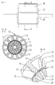
- Fig. 1 shows an external view of a DC motor according to the invention.
- a stator 10 can be seen, in which a sleeve 12 is applied to the stator teeth, which projects axially at both ends of the stator 10.
- the stator body 10 includes a stator return ring 14 from which stator teeth 16 extend inwardly in the radial direction.
- the stator teeth are coupled at their free ends to the sleeve 12.
- the sleeve has slot-shaped recesses 18 which are engaged with the free ends of the stator teeth 16, wherein in the illustrated embodiment, the stator teeth 16 have at their free ends a connecting portion 20 which is pressed or pushed into the recesses 18.
- the sleeve further has slots 22, which are arranged approximately in the middle between two adjacent recesses 20 and associated stator teeth 16.
- the sleeve may be stiffened by beads or folds or the like (not shown).
- the sleeve 12 protrudes in the axial direction in relation to the front ends of the stator body 10. It delimits the stator body 10 against a rotor space.
- a rotor Coaxially within the stator body 10, a rotor is arranged, which is shown schematically by a rotor body 24 in the figures.
- the rotor body 24 has spoke-shaped recesses 26 for receiving permanent magnets, the recesses 26 being connected in pairs.
- the rotor body 24 is applied to a shaft 28. Between the rotor body 24 and the stator body 10, a working air gap 30 is formed.
- stator teeth 16 are substantially rectangular without the broadening of their free ends common in the prior art to form pole pieces. This allows a simple winding of the stator body 10, because the slot opening between two adjacent pole teeth 16 is very far. Alternatively, it is possible to postpone already pre-wound coils together with bobbin from the inside to the stator teeth 16.
- the sleeve 12 is applied after the winding of the stator teeth 16 on the free ends and thus also serves as a groove cover. Suitably, it is coated on its surface facing the stator with an electrically insulating material.
- the sleeve 12 is made of a ferroelectric material and magnetically coupled to the stator teeth.
- the sleeve 12 forms the pole pieces at the end of the stator teeth 16, with adjacent pole pieces being separated by the slots 22 formed in the sleeve.
- a stator arrangement with pole shoes can be produced whose slot opening is smaller than is usual in the prior art.
- the rule is that the slot opening must be about ⁇ 1.5 times the wire diameter, which must be passed through the slot opening. This limitation does not have to be complied with in the stator arrangement according to the invention. This results in a stator that achieves extremely low torque fluctuations and a relatively high flux concentration during operation.
- the sleeve 12 is preferably formed so that it protrudes at the axial ends of the stator body 10. This has the advantage that the axial, the slots 22 bridging webs 34, which are necessary for the cohesion of the sleeve, are outside the range of action of the rotor and thus can not form a magnetic short circuit. Furthermore, the sleeve 22 at the front end of the stator assembly 10 shields the magnetic field generated by the stator in the direction of the rotor. Magnetic sensors for detecting the rotational position of the electrical machine, for example, Hall sensors or magnetoresistive sensors, are often arranged on the stator or on the flange opposite the front side of the rotor.
- these are preferably arranged in the vicinity of the outer circumference of a rotor. This is especially the case when the rotor is not, as in the embodiment shown, embedded permanent magnets but the permanent magnets are arranged on the outer circumference of the rotor. Nearby However, the circumference of the rotor also affects the magnetic field generated by the winding head, which is largely shielded in the invention by the axial projecting sleeve 12.
- a possible position for a rotational position sensor is indicated by the arrow S.
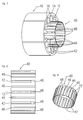
- the sleeve 12 may be coated on its inside and / or its outside with an electrically insulating material.
- the sleeve is preferably punched out of a metal sheet and then rolled, wherein the sleeve 12 can remain open at a seam 32.
- the sleeve 12 is sufficiently flexible to introduce it in the axial direction in the interior of the stator body 10 and press with the recesses 18 on the stator teeth 16.
- the geometry of the free ends of the stator teeth 16 and the recesses 18 must be suitably adapted to each other.
- the recesses 18 and the slots 22 are bridged at both axial ends of the sleeve 12 by webs 34.
- the recesses 18 at one axial end of the sleeve 12 are open. This makes it possible for the sleeve 12 to be pushed onto the stator teeth 16 in the axial direction.
- the slots 22 are open at one axial end of the sleeve, whereby the risk of the formation of a magnetic short circuit through the sleeve 12 is reduced. It can also be provided to separate the sleeve 12 after application to the stator teeth 16 in the region of the slots 22 in order to completely separate adjacent pole pieces for magnetic optimization.
- stator assembly may be appropriate to encase the wound stator assembly after applying the sleeve 12 with a plastic in order to increase the stability of the stator assembly.
- the separation of the sleeve 12 may take place after the stator assembly has been embedded in plastic.
- Fig. 6 shows a schematic sectional view through a section of an electric machine according to another embodiment of the invention, which is similar to Fig. 2b. Corresponding parts are denoted by the same reference numerals and not explained again in detail.
- the stator teeth 16 in the vicinity of their free ends on lateral grooves 36, in which the sleeve 12 - in axial Direction of the stator - can be inserted.
- the recesses 18 of the sleeve 12 are open at one end to insert the sleeve 12 with the edges of the recesses 18 in the slots 36.
- This embodiment has the advantage that the sleeve can not be pulled off the stator teeth or poles as a result of the magnetic attraction of the rotor magnets.
- the sleeve is preferably made of a magnetically conductive, i. ferromagnetic, material. However, if it is only intended to fulfill the function of a slot cover, it can also be made of a non-magnetic material.
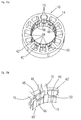
- FIG. 7 to 9 A second embodiment of the stator assembly according to the invention is shown in Figs. 7 to 9 and a modification of this embodiment in Figs. 10a and 10b.
- this embodiment does not differ from that described above.
- Corresponding parts are identified by the same reference numerals.
- the sleeve is constructed differently than in the first embodiment.
- the sleeve 40 is made of a magnetic material which is ferromagnetic in a first state and paramagnetic in a second state.
- This magnetic material is also referred to as a bi-permeable material.
- the preferred material for the sleeve according to the second embodiment is a YEP FA1 steel developed by Hitachi Metals Ltd., Tokyo, Japan. This is an alloy based on Fe-Cr-C, which additionally contains amounts of Si, Mn, Ni or Al. This material has a starting ferromagnetic state with a relative magnetic permeability of about 900 and a paramagnetic state with a relative magnetic permeability as low as 1.01.
- the material can be converted from the ferromagnetic to the paramagnetic state by heating it to a temperature above 1050 ° C, especially above 1100 ° C, preferably in the range of 1100 ° C and 1200 ° C.
- a particularly preferred temperature range is between 1150 ° C and the melting temperature of the material.
- the entire sleeve 40 is made of this material, wherein the sleeve is preferably punched out of a sheet and recesses 42 are formed during the punching. Subsequently, the sleeve is rolled, wherein it can initially remain open at a seam 44. The sleeve 40 is slid with the recesses 42 on the stator teeth 16 in the axial direction, as described above with reference to the first embodiment. Alternatively, the sleeve 40 can also be pressed onto the stator teeth 16.
- the sleeve 40 is locally heated in the region of axially extending zones 46, whereby the sleeve 40 is brought in the region of these zones 46 in the paramagnetic state.
- the zones 46 are selected to provide complete magnetic separation of the individual stator poles formed by the stator teeth 16 and the adjacent portions of the sleeve 40, the zones 46 each being symmetrical between two adjacent stator poles.
- the heating can be generated for example by means of laser or induction welding, which is preferably of the order of 1150 ° C.
- the heating of the zones 46 of the sleeve 40 can be done before or after the roll of the sleeve; it is preferably done before.
- the sleeve is preferably formed so as to protrude at the axial ends of the stator body 10.
- the webs 48 at the ends of the sleeve 40 which bridge the recesses 42 and are necessary for the cohesion of the sleeve, also heated and thereby converted into the paramagnetic state. In this way, magnetic short circuits in this area can be completely avoided.
- the sleeve 40 may be coated on its inside with an electrically insulating material.
- the recesses 42 are bridged by the webs 48 only at one axial end of the sleeve 40.
- the recesses 42 could be provided that the recesses 42 are bridged at both axial ends of the sleeve 40 in order to give the sleeve additional stability. In this case, it would not be possible to push the sleeve on the stator body 10 in the axial direction, but the sleeve could be pressed onto the stator teeth 16 from the inside. It may be appropriate to encase the wound stator assembly after applying the sleeve 40 with a plastic to increase the stability of the stator assembly.
- the sleeve 40 is slid onto an axial end of the stator body 10.
- a modification of this embodiment is shown in Figs. 10a to 10b, wherein in this modification, the sleeve is constructed in two parts, so that it can be pushed from the two opposite axial ends of the stator 10.
- the two sleeve halves 40 'of the two-part sleeve can basically be constructed in the same way as the one-part sleeve 40 shown in FIGS. 8 and 9, wherein the sleeve is only shortened in the axial direction so as to push the two halves 40' on both sides of the stator body. that they complement each other to a sleeve which extends substantially over the entire axial length of the stator.
- a gap 50 between the sleeve halves 40 ' is shown, they are preferably as far pushed onto the stator body 10 that they touch at their front ends, whereby a small gap is tolerable.
- the second embodiment has the advantage of increased mechanical stability as well as complete magnetic separation of the individual poles of the stator assembly. However, it generates eddy currents to some extent, which can be suppressed by the measures described below.
- the sleeve is constructed of individual mutually electrically insulated layers.
- sheets of bi-permeable material are preferably stacked and stamped into sheet metal strips, which are initially designed linear and serve as a base for the sleeve.
- the areas which are to form the demagnetized zones are demagnetized by heat treatment, for example by means of laser or induction welding, and at the same time the individual sheets are thereby connected to one another.
- the recesses for pushing the sleeve on the stator teeth are removed, for example by punching, and the sleeve is rolled and possibly joined together at their ends. Due to the sheet metal structure of the sleeve eddy currents can be avoided within the sleeve material.
Abstract
Description
Die Erfindung betrifft eine Statoranordnung für eine elektrische Maschine, ein Verfahren zur Herstellung einer Statoranordnung und einen Gleichstrommotor, der eine solche Statoranordnung verwendet. Die erfindungsgemäße Statoranordnung kann in unterschiedlichsten Arten elektrischer Maschinen eingesetzt werden und ist insbesondere für Gleichstrommotoren und - generatoren vorgesehen.The invention relates to a stator assembly for an electric machine, a method for manufacturing a stator assembly, and a DC motor using such a stator assembly. The stator arrangement according to the invention can be used in a wide variety of types of electrical machines and is provided in particular for DC motors and generators.
Ein bevorzugtes Anwendungsgebiet der Erfindung sind bürstenlose Gleichstrommotoren und andere Permanentmagnetmotoren, die vorzugsweise als Innenläufermotoren konfiguriert sind. Elektromotoren mit einer permanentmagnetischen Innenläuferkonfiguration weisen einen Rotorrückschluß auf, der auf eine Welle aufgebracht ist, wobei ein oder mehrere Permanentmagnete auf den Rotorrückschluß aufgebracht oder in diesen eingebettet sind. Ferner umfassen die Motoren eine Statoranordnung, die üblicherweise aus einer Anzahl paketierter Metallbleche aufgebaut ist, welche einen ringförmigen Statorrückschluß bilden, von dem Statorzähne radial nach innen abstehen. Die Statorzähne bilden die Statorpole, zwischen denen Statornuten zur Aufnahme von Wicklungen gebildet sind. Die Rotoranordnung ist koaxial in die Statoranordnung eingefügt. Die Erfindung ist auch anwendbar auf Außenläufermotoren.A preferred field of application of the invention are brushless DC motors and other permanent magnet motors, which are preferably configured as internal rotor motors. Electric motors with a permanent magnetic internal rotor configuration have a rotor return, which is applied to a shaft, wherein one or more permanent magnets are applied to the rotor yoke or embedded in these. Further, the motors include a stator assembly which is typically constructed of a number of packetized metal sheets forming an annular stator yoke from which stator teeth project radially inwardly. The stator teeth form the stator poles, between which stator slots for receiving windings are formed. The rotor assembly is coaxially inserted into the stator assembly. The invention is also applicable to external rotor motors.
Es ist üblich, daß Rotor und Stator in einem Gehäuse aufgenommen sind, das wenigstens einen stirnseitigen Flansch zur Befestigung des Motors aufweist. Jedoch sind auch Motoren bekannt, bei denen die Außenseite des Statorblechpakets den Motor nach außen hin abschließt. Bei den meisten Motoren besteht der Stator aus einem genuteten Blechpaket, wobei die Wicklungen, beispielsweise aus isoliertem Kupferdraht in den Nuten des Stators aufgenommen werden. Üblicherweise sind die Statorzähne an ihren freien Enden verbreitert und weisen sogenannte Polschuhe auf, die dazu dienen, soviel magnetischen Fluß wie möglich aufzunehmen und durch ihre Gestaltung das Rastmoment der Maschine zu reduzieren. Die Polschuhe haben die zusätzliche Funktion, daß sie die Wicklungen innerhalb der Nuten in ihrer Position fixieren. Zur Verminderung des Rastmomentes einer elektrischen Maschine und zur Optimierung des Magnetflusses sollten die Polschuhe so breit wie möglich sein. Ein Nachteil breiter Polschuhe ist jedoch, daß sie nur einen relativ schmalen Spalt zum Hindurchführen des Wicklungsdrahtes in die Statornuten offen lassen.It is common for the rotor and stator to be housed in a housing having at least one end flange for mounting the motor. However, engines are also known in which the outer side of the stator lamination stack closes the motor to the outside. In most motors, the stator consists of a grooved laminated core, with the windings, for example of insulated copper wire, being received in the slots of the stator. Usually, the stator teeth are widened at their free ends and have so-called pole pieces, which serve to absorb as much magnetic flux as possible and reduce the detent torque of the machine by their design. The pole pieces have the additional function of winding the coils inside the slots fix their position. To reduce the cogging torque of an electrical machine and to optimize the magnetic flux pole shoes should be as wide as possible. However, a disadvantage of wide pole shoes is that they leave only a relatively narrow gap open for passing the winding wire into the stator slots.
Es ist daher die Aufgabe der Erfindung, eine Statoranordnung für eine elektrische Maschine anzugeben, die bezüglich der Magnetflußfiihrung und des Rastmoments gute Eigenschaften aufweist und gleichwohl ein einfaches Bewickeln der Statorzähne erlaubt.It is therefore an object of the invention to provide a stator assembly for an electrical machine, which has good properties with respect to the Magnetflußfiihrung and the cogging torque and nevertheless allows easy winding of the stator teeth.
Diese Aufgabe wird durch eine Statoranordnung mit den Merkmalen von Patentanspruch 1 gelöst. Die Erfindung sieht auch einen Gleichstrommotor gemäß Anspruch 11 sowie ein Verfahren zur Herstellung einer Statoranordnung für eine elektrische Maschine gemäß Anspruch 12 vor.This object is achieved by a stator arrangement having the features of patent claim 1. The invention also provides a DC motor according to claim 11 and a method for producing a stator assembly for an electrical machine according to
Die Erfindung sieht eine Statoranordnung für eine elektrische Maschine und insbesondere für einen Gleichstrommotor vor, die einen Statorkörper mit einem Statorrückschlußring und mehreren Statorzähnen aufweist. Die Statorzähne erstrecken sich von dem Statorrückschlußring in radialer Richtung und grenzen zwischen sich Statornuten zur Aufnahme von Wicklungen ein. An den freien Enden der Statorzähne sind Statorpole gebildet. In ihrer bevorzugten Ausführung der Erfindung ist die Statoranordnung für einen Innenläufermotor vorgesehen, wobei die Statorzähne sich in dieser Konfiguration von dem Statorrückschlußring in radialer Richtung nach innen erstrecken. Die Statorzähne weisen an ihren freien Enden keine sich verbreiternde Polschuhe auf, wie das im Stand der Technik üblich wäre. Die Nutöffnungen zwischen den Statorzähnen sind daher weit, und das Einführen der Wickeldrähte in die Nutöffnung zum Bewickeln der Statorzähne ist deutlich einfacher als bei üblichen Statoranordnungen für Innenläufermotoren. Nach dem Bewickeln der Statorzähne wird auf die erfindungsgemäße Statoranordnung eine Hülse aufgebracht, die sich koaxial zu dem Statorkörper erstreckt und mit den freien Enden der Statorzähne gekoppelt wird. In einer Innenläuferkonfiguration bestimmt die Hülse den Innendurchmesser des Stators und schließt diesen gegenüber dem Rotor ab.The invention provides a stator assembly for an electric machine and in particular for a DC motor, which has a stator body with a stator yoke ring and a plurality of stator teeth. The stator teeth extend radially from the stator return ring and define stator slots between them to receive windings. Stator poles are formed at the free ends of the stator teeth. In its preferred embodiment of the invention, the stator assembly is for an internal rotor motor, the stator teeth extending radially inwardly from the stator yoke ring in this configuration. The stator teeth have no widening pole shoes at their free ends, as would be customary in the prior art. The groove openings between the stator teeth are therefore wide, and the insertion of the winding wires in the slot opening for winding the stator teeth is much easier than in conventional stator arrangements for internal rotor motors. After winding the stator teeth, a sleeve is applied to the stator assembly according to the invention, which extends coaxially to the stator and is coupled to the free ends of the stator teeth. In an internal rotor configuration, the sleeve determines the inner diameter of the stator and closes it off from the rotor.
Die Hülse hat in der erfindungsgemäßen Statoranordnung mehrere Funktionen. Zunächst dient sie als Nutabdeckung und hält die Wicklungen in den Statornuten. Für diese Funktion ist es zweckmäßig, die Hülse auf ihrer den Statornuten zugewandten Oberfläche mit einem elektrisch isolierenden Material zu beschichten, so daß sie auch die Funktion einer Nutisolierung übernimmt. Eine weitere, noch wichtigere Funktion der Hülse ist die Bildung von Polschuhen. Zur Erfüllung dieser Aufgabe besteht die Hülse zweckmäßig aus einem ferromagnetischen Material, wobei sie mit den freien Enden der Statorzähne magnetisch gekoppelt ist. Ferner ist die Hülse vorzugsweise so gestaltet, daß sie zwischen jeweils zwei benachbarten Statorzähnen in axialer Richtung verlaufende nicht- oder schwachmagnetische Zonen aufweist, um die Polschuhe benachbarter Statorzähne magnetisch voneinander zu trennen. Diese Zonen zwischen den Polschuhen können schmal sein, weil sie lediglich die Funktion haben, die Polschuhe magnetisch voneinander zu trennen. Dadurch kann eine Statoranordnung mit besonders breiten Polschuhen erhalten werden, die günstig für das Laufverhalten der elektrischen Maschine ist und insbesondere eine Reduzierung des Rastmoments ermöglicht.The sleeve has several functions in the stator assembly according to the invention. First, it serves as a slot cover and holds the windings in the stator slots. For this feature is it is expedient to coat the sleeve on its surface facing the stator grooves with an electrically insulating material, so that it also assumes the function of a slot insulation. Another more important function of the sleeve is the formation of pole pieces. To achieve this object, the sleeve is expediently made of a ferromagnetic material, wherein it is magnetically coupled to the free ends of the stator teeth. Further, the sleeve is preferably designed so that it has between each two adjacent stator teeth in the axial direction extending non-weak or weak magnetic zones to magnetically separate the pole pieces of adjacent stator teeth from each other. These zones between the pole shoes can be narrow because they only have the function of magnetically separating the pole pieces. As a result, a stator arrangement with particularly wide pole shoes can be obtained, which is favorable for the running behavior of the electric machine and in particular allows a reduction of the cogging torque.
In einer ersten Ausführung der Erfindung werden die Zonen zur Trennung der Polschuhe durch schmale Schlitze gebildet, welche aus der Hülse z.B. ausgestanzt werden. Die Hülse besteht in dieser Ausführung vorzugsweise aus ferromagnetischem Material.In a first embodiment of the invention, the zones for separating the pole pieces are formed by narrow slots formed from the sleeve, e.g. be punched out. The sleeve is preferably made of ferromagnetic material in this embodiment.
In einer weiteren Ausführung der Erfindung ist die Hülse aus einem bi-permeablen Material hergestellt, das in einem ersten Zustand ferromagnetisch ist und in einem zweiten Zustand paramagnetisch ist. Dieses Material hat in seinem Ausgangszustand ferromagnetische und nach Wärmebehandlung paramagnetische Eigenschaften. Die Hülse wird in dem Bereich, in dem die nicht- oder schwachmagnetischen Zonen entstehen sollen, lokal begrenzt erhitzt und so innerhalb dieser Zonen in den paramagnetischen Zustand gebracht.In a further embodiment of the invention, the sleeve is made of a bi-permeable material which is ferromagnetic in a first state and paramagnetic in a second state. This material has ferromagnetic properties in its initial state and paramagnetic properties after heat treatment. The sleeve is locally heated in the area in which the non-magnetic or weakly magnetic zones are to be formed and thus brought into the paramagnetic state within these zones.
Ein Material, das sich für die Herstellung der Hülse gemäß der Erfindung eignet, ist eine Legierung auf der Basis von Fe-Cr-C, die von Hitachi Metals Ltd., Tokyo, Japan, unter der Bezeichnung YEP FA1-Stahl hergestellt wird. Diese Legierung ist beispielsweise beschrieben in den US-Patenten 6,255,005 und 6,390,443, sowie in den japanischen Offenlegungsschriften JP 2004 091842, JP 2004 143585 und JP 2004 281737. Auf diese Schriften wird in bezug auf die Zusammensetzung des bi-permeablen Materials sowie auf die darin offenbarten Temperaturbereiche, insbesondere Temperaturen zum Umwandeln des bi-permeablen Materials von dem ferromagnetischen in den paramagnetischen Zustand Bezug genommen. In den genannten Veröffentlichungen wird das bi-permeable Material in elektromagnetischen Ventilen und anderen Magnetbauteilen verwendet; eine Verwendung in Statoranordnungen ist weder beschrieben noch angedacht.A material suitable for making the sleeve according to the invention is an Fe-Cr-C based alloy manufactured by Hitachi Metals Ltd., Tokyo, Japan under the name YEP FA1 steel. This alloy is described, for example, in US Pat. Nos. 6,255,005 and 6,390,443, and Japanese Patent Laid-Open Publication Nos. 2004-091842, JP 2004143585 and JP 2004-281737. These publications are related to the composition of the bi-permeable material as well as those disclosed therein Temperature ranges, particularly temperatures for converting the bi-permeable material from the ferromagnetic to the paramagnetic state. In the cited publications, the bi-permeable material in electromagnetic valves and used other magnetic components; use in stator arrangements is neither described nor intended.
In einer vorteilhaften Ausführung der Erfindung ist die Hülse auch auf ihrer von den Statornuten abgewandten Oberfläche mit elektrisch isolierendem Material beschichtet, um eine elektrische Isolation gegenüber dem Rotor z.B. zur Vermeidung von Spannungsüberschlägen im Fehlerfall vorzusehen.In an advantageous embodiment of the invention, the sleeve is also coated on its surface remote from the stator slots with electrically insulating material to provide electrical insulation from the rotor, e.g. to avoid voltage flashovers in the event of a fault.
Die erfindungsgemäße Statoranordnung kann auf besonders einfache und kostengünstige Weise hergestellt werden, wenn die Hülse aus einem gestanzten, gerollten und gegebenenfalls beschichteten Blech hergestellt wird. In der ersten Ausführung wird die Hülse zunächst aus einem flachen Blech gestanzt, wobei Schlitze zur Trennung der einzelnen Polschuhe sowie Ausnehmungen zur Verbindung mit den Statorzähnen mitausgestanzt werden. Anschließend wird das Blech zu einer Hülse gerollt, die an einer Nahtstelle offen und dadurch flexibel ist. Dies erleichtert das Aufbringen bzw. Aufdrücken der Hülse auf die freien Enden der Statorzähne. Es ist zweckmäßig, die freien Enden der Statorzähne mit einer entsprechenden Paßform zu versehen, die mit den Ausnehmungen in der Hülse zusammenwirkt. Es sind verschiedene Ausführungen der Hülse denkbar. So können die Ausnehmungen zur Verbindung mit den Statorzähnen durch sich in axialer Richtung entlang der Hülse erstreckende Schlitze gebildet sein, die an beiden axialen Enden der Hülse geschlossen sind. In dieser Ausführung werden die Ausnehmungen auf die Statorzähne gedrückt. In einer alternativen Ausführung sind die Ausnehmungen durch Schlitze gebildet, die an nur einem axialen Ende der Hülse geschlossen sind. In dieser Ausführung kann die Hülse in axialer Richtung auf den Statorkörper bzw. die Statorzähne aufgeschoben werden. In einer weiteren Ausführung der Erfindung sind in den Statorzähnen in der Nähe ihrer freien Enden seitliche Schlitze ausgebildet, um die Hülse in axialer Richtung so auf die Statorzähne aufzuschieben, daß die Kanten der Ausnehmungen in die Schlitze eingreifen. Dies hat den Vorteil, daß die Hülse nicht in Folge der magnetischen Anziehungskraft der Rotormagneten von den Statorpolen abgezogen werden kann. Zusätzlich oder alternativ kann die Hülse mit den Statorzähnen fest verbunden werden, beispielsweise durch Schweißen, insbesondere Laserschweißen, oder Kleben. Um der Hülse größere Stabilität zu verleihen, kann es zweckmäßig sein, die Naht der gerollten Hülse nach dem Aufbringen auf den Statorkörper zu schließen. Eine offene Naht hat den Vorteil, daß beim Ausstanzen der Hülse größere Toleranzen gewährt werden können und die Hülse flexibler ist.The stator assembly according to the invention can be produced in a particularly simple and cost-effective manner, when the sleeve is made from a stamped, rolled and optionally coated sheet metal. In the first embodiment, the sleeve is first punched from a flat sheet, with slots for the separation of the individual pole pieces and recesses for connection with the stator teeth are mitausgestanzt. Subsequently, the sheet is rolled into a sleeve which is open at a seam and thus flexible. This facilitates the application or pressing of the sleeve on the free ends of the stator teeth. It is expedient to provide the free ends of the stator teeth with a corresponding fit, which cooperates with the recesses in the sleeve. There are different versions of the sleeve conceivable. Thus, the recesses for connection to the stator teeth may be formed by slots extending in the axial direction along the sleeve which are closed at both axial ends of the sleeve. In this embodiment, the recesses are pressed onto the stator teeth. In an alternative embodiment, the recesses are formed by slots which are closed at only one axial end of the sleeve. In this embodiment, the sleeve can be pushed in the axial direction of the stator or the stator teeth. In a further embodiment of the invention, lateral slots are formed in the stator teeth near their free ends to slid the sleeve in the axial direction onto the stator teeth so that the edges of the recesses engage in the slots. This has the advantage that the sleeve can not be deducted from the stator poles as a result of the magnetic attraction of the rotor magnets. Additionally or alternatively, the sleeve can be firmly connected to the stator teeth, for example by welding, in particular laser welding, or gluing. To give the sleeve greater stability, it may be appropriate to close the seam of the rolled sleeve after application to the stator body. An open seam has the advantage that greater tolerances can be granted when punching out the sleeve and the sleeve is more flexible.
Es ist auch eine Ausführung der Erfindung denkbar, bei der die Hülse zunächst auf die Statorzähne aufgedrückt oder aufgeschoben wird und bei der anschließend die Hülse im Bereich der die Polschuhe trennenden Schlitze aufgetrennt wird, um vollständig voneinander getrennte Polschuhe zu bilden. Zur Stabilisierung dieser oder anderer Ausführungen der erfindungsgemäßen Statoranordnung kann ferner vorgesehen sein, den bewickelten Stator mit Kunststoff zu umspritzen.It is also an embodiment of the invention conceivable in which the sleeve is first pressed or pushed onto the stator teeth and in which subsequently the sleeve is separated in the region of the pole shoes separating slots to form completely separate pole pieces. To stabilize these or other embodiments of the stator assembly according to the invention may also be provided to overmold the wound stator with plastic.
In ihrer zweiten Ausführung wird die Hülse, ähnlich wie in der ersten Ausführung, aus einem flachen Blech gestanzt, wobei dieses Blech aus dem bi-permeablen Material der oben beschriebenen Art besteht. Ausnehmungen zur Verbindung der Hülse mit dem Statorzähnen werden mit ausgestanzt, Schlitze zur Trennung der einzelnen Pole des Stators sind jedoch nicht notwendig. Anschließend wird das Blech zu einer Hülse gerollt, die an einer Nahtstelle offen und dadurch flexibel ist. Die Hülse kann in axialer Richtung auf die Statorzähne aufgeschoben oder auf diese aufgedrückt werden. Vor oder nach dem Aufbringen der Hülse auf die Statorzähne, vorzugsweise vor dem Rollen des Bleches zu einer Hülse wird dieses innerhalb der in axialer Richtung verlaufenden Zonen, die jeweils zwischen zwei benachbarten Statorzähnen liegen, lokal erwärmt, um das bi-permeable Material innerhalb dieser begrenzten Zonen von dem ferromagnetischen Ausgangszustand in den paramagnetischen Zustand zu überführen. Zu diesem Zweck werden die Zonen vorzugsweise auf eine Temperatur > 1150° beispielsweise mittels Laser- oder Induktionsschweißen erwärmt. Während diese zweite Ausführung den zusätzlichen Arbeitsschritt der lokal begrenzten Erwärmung der Hülse erfordert, hat sie den Vorteil, daß die Hülse im Vergleich zu der geschlitzten Hülse eine bessere mechanische Stabilität aufweist. Magnetische Kurzschlüsse im Bereich des Stirnendes der Hülse, an dem bei der ersten Ausführung die Schlitze überbrückt sind, können vermieden werden.In its second embodiment, the sleeve, similar to the first embodiment, is stamped from a flat sheet, this sheet being made of the bi-permeable material of the type described above. Recesses for connecting the sleeve with the stator teeth are punched with, but slots for the separation of the individual poles of the stator are not necessary. Subsequently, the sheet is rolled into a sleeve which is open at a seam and thus flexible. The sleeve can be pushed onto the stator teeth in the axial direction or pressed onto them. Before or after the sleeve is applied to the stator teeth, preferably before the sheet is rolled into a sleeve, it is locally heated within the axially extending zones, each between two adjacent stator teeth, about the bi-permeable material within it To convert zones from the ferromagnetic initial state to the paramagnetic state. For this purpose, the zones are preferably heated to a temperature> 1150 °, for example by means of laser or induction welding. While this second embodiment requires the additional operation of localized heating of the sleeve, it has the advantage that the sleeve has better mechanical stability compared to the slotted sleeve. Magnetic short circuits in the region of the front end of the sleeve, on which the slots are bridged in the first embodiment, can be avoided.
Um die fertige Statoranordnung zu stabilisieren, kann sie mit einem Kunststoff oder Kunstharz umgossen werden. Die Hülse selbst kann ferner durch Sicken oder Abkantungen versteift werden.In order to stabilize the finished stator assembly, it can be encapsulated with a plastic or synthetic resin. The sleeve itself can also be stiffened by beads or folds.
Versuche mit der erfindungsgemäßen Statoranordnung in der Praxis haben gezeigt, daß die Hülse einen gewissen Anteil an Wirbelströmen erzeugt, wobei dieser Effekt in der Ausführung mit den Schlitzen geringer ist als in der Ausführung, in der die Hülse aus dem bi-permeablen Material hergestellt ist. Das Problem der Wirbelstrombildung läßt sich minimieren, indem die Hülse aus einzelnen gegeneinander elektrisch isolierten Lagen aufgebaut wird, ähnlich wie bei der Herstellung eines Statorkörpers aus einem gestanzten Blechstapel. Vorzugsweise werden zu diesem Zweck eine Reihe von Blechen aus ferromagnetischem Material oder aus dem bi-permeablen Material gestapelt und in schmalen Blechstreifen ausgestanzt. Anschließend werden die Bleche miteinander verbunden. Wenn die Bleche aus dem bi-permeablen Material hergestellt sind, bietet es sich an, die Bleche im Bereich der Zonen durch Wärmebehandlung, beispielsweise mittels Laser- oder Induktionsschweißen, in einen paramagnetischen Zustand zu überführen und gleichzeitig innerhalb dieser Bereiche miteinander zu verbinden. Anschließend werden die Ausnehmungen zum Aufschieben der Hülse auf die Statorzähne entfernt, beispielsweise ausgestanzt, und die Hülse wird rolliert und gegebenenfalls an ihren Enden miteinander verbunden. Der Vorteil dieser Anordnung ist, daß aufgrund der Blechstruktur Wirbelströme innerhalb des Hülsenmaterials praktisch vollständig vermieden werden.Experiments with the stator assembly according to the invention in practice have shown that the sleeve generates a certain amount of eddy currents, this effect being less in the embodiment with the slots than in the embodiment in which the sleeve is made of the bi-permeable material. The problem of eddy current formation can be minimized in that the sleeve is constructed from individual mutually electrically insulated layers, similar to the production of a stator body from a stamped sheet stack. Preferably, for this purpose, a series of sheets of ferromagnetic material or of the bi-permeable material are stacked and punched into narrow sheet metal strips. Then the sheets are joined together. If the sheets are made of the bi-permeable material, it is advisable to bring the sheets in the zone by heat treatment, for example by means of laser or induction welding, in a paramagnetic state and simultaneously to connect within these areas. Subsequently, the recesses for pushing the sleeve on the stator teeth are removed, for example, punched out, and the sleeve is rolled and optionally joined together at their ends. The advantage of this arrangement is that due to the sheet structure eddy currents within the sleeve material are virtually completely avoided.
In einer besonders bevorzugten Ausführung der Erfindung steht wenigstens ein axiales Ende der Hülse über ein Stirnende des Statorkörpers in axialer Richtung vor. Diese Ausführung hat den Vorteil, daß die an den axialen Stirnenden angeordneten Stege, welche die Hülse zusammenhalten und die Polschuhe überbrücken, außerhalb des Magnetfeldes des Rotors angeordnet werden können. Dadurch wird verhindert, daß die Hülse im Bereich des Rotors einen magnetischen Kurzschluß bildet. Ein weiterer Vorteil einer Hülse, die über wenigstens ein Stirnende des Statorkörpers in axialer Richtung vorsteht, ist, daß sie Stator-Magnetfelder zum Rotor hin abschirmt. Dies ist insbesondere bei solchen Maschinen sinnvoll, bei denen am Stator bzw. am Flansch der Stirnseite des Rotors gegenüberliegend ein Magnetsensor zur Erfassung der Drehlage angebracht ist. Durch die abschirmende Wirkung der axial vorstehenden Hülse werden diese Magnetsensoren nicht durch das Magnetfeld des Stators beeinflußt und können somit die Drehlage des Rotors genauer bestimmen.In a particularly preferred embodiment of the invention, at least one axial end of the sleeve projects beyond a front end of the stator body in the axial direction. This embodiment has the advantage that the webs arranged at the axial ends, which hold the sleeve together and bridge the pole shoes, can be arranged outside the magnetic field of the rotor. This prevents that the sleeve forms a magnetic short circuit in the region of the rotor. Another advantage of a sleeve projecting in the axial direction over at least one front end of the stator body is that it shields stator magnetic fields toward the rotor. This is particularly useful in such machines, in which on the stator or on the flange of the front side of the rotor opposite a magnetic sensor for detecting the rotational position is mounted. Due to the shielding effect of the axially projecting sleeve, these magnetic sensors are not affected by the magnetic field of the stator and thus can more accurately determine the rotational position of the rotor.
Die Erfindung ist im folgenden anhand bevorzugter Ausführungen in bezug auf die Zeichnung näher erläutert. In den Figuren zeigen:
- Fig. 1
- eine Außenansicht einer elektrischen Maschine gemäß der Erfindung;
- Fig. 2a
- eine schematische Schnittdarstellung durch die elektrische Maschine der Fig. 1 entlang der Linie X-X gemäß einer ersten Ausführung;
- Fig. 2b
- eine vergrößerte Detailansicht der Fig. 2a;
- Fig. 3
- eine auseinandergezogene perspektivische Darstellung der elektrischen Maschine gemäß der ersten Ausführung der Erfindung;
- Fig. 4
- eine ähnliche Darstellung wie in Fig. 3, jedoch in zusammengesetztem Zustand; und
- Fig. 5
- eine perspektivische Darstellung einer Hülse gemäß der ersten Ausführung, die in der erfindungsgemäßen Stator-anordnung eingesetzt ist;
- Fig. 6
- eine schematische Schnittdarstellung durch einen Teil einer elektrischen Maschine gemäß einer Abwandlung der ersten Ausführung der Erfindung, die ähnlich der Darstellung der Fig. 2b ist;
- Fig. 7
- eine auseinandergezogene perspektivische Darstellung einer Statoranordnung gemäß einer zweiten Ausführung der Erfindung;
- Fig. 8
- eine Seitenansicht einer Hülse gemäß der zweiten Ausführung, die in der erfindungsgemäßen Statoranordnung eingesetzt ist;
- Fig. 9
- eine perspektivische Darstellung der Hülse der Fig. 8;
- Fig. 10a
- eine perspektivische Darstellung der Statoranordnung gemäß einer Abwandlung der zweiten Ausführung der Erfindung; und
- Fig. 10b
- eine vergrößerte Detailansicht der Fig. 10a.
- Fig. 1
- an external view of an electrical machine according to the invention;
- Fig. 2a
- a schematic sectional view through the electric machine of Figure 1 along the line XX according to a first embodiment.
- Fig. 2b
- an enlarged detail view of Fig. 2a;
- Fig. 3
- an exploded perspective view of the electrical machine according to the first embodiment of the invention;
- Fig. 4
- a similar view as in Figure 3, but in an assembled state. and
- Fig. 5
- a perspective view of a sleeve according to the first embodiment, which is used in the stator assembly according to the invention;
- Fig. 6
- a schematic sectional view through part of an electric machine according to a modification of the first embodiment of the invention, which is similar to the representation of Figure 2b.
- Fig. 7
- an exploded perspective view of a stator assembly according to a second embodiment of the invention;
- Fig. 8
- a side view of a sleeve according to the second embodiment, which is used in the stator assembly according to the invention;
- Fig. 9
- a perspective view of the sleeve of Fig. 8;
- Fig. 10a
- a perspective view of the stator according to a modification of the second embodiment of the invention; and
- Fig. 10b
- an enlarged detail view of Fig. 10a.
Die Erfindung ist im folgenden anhand des Beispiels eines bürstenlosen Gleichstrommotors beschrieben, wobei ein Fachmann jedoch verstehen wird, daß die Grundsätze der Erfindung auf unterschiedlichste Art elektrischer Maschinen, einschließlich Generatoren, anwendbar sind.The invention will now be described by way of example of a brushless DC motor, however, it will be understood by those skilled in the art that the principles of the invention are applicable to a wide variety of electrical machines, including generators.
Die Erfindung ist im folgenden mit Bezug auf die Figuren beschrieben, wobei zunächst Bezug genommen wird auf die Fig. 1 bis 4.The invention is described below with reference to the figures, wherein first reference is made to Figs. 1 to 4.
Fig. 1 zeigt eine Außenansicht eines Gleichstrommotors gemäß der Erfindung. In der Außenansicht der Fig. 1 ist ein Statorkörper 10 zu erkennen, in dem eine Hülse 12 auf die Statorzähne aufgebracht ist, die an beiden Stirnenden des Statorkörpers 10 axial vorsteht. Wie in den Fig. 2a, 2b, 3 und 4 dargestellt, umfaßt der Statorkörper 10 einen Statorrückschlußring 14, von dem sich Statorzähne 16 in radialer Richtung nach innen erstrecken. Die Statorzähne sind an ihren freien Enden mit der Hülse 12 gekoppelt. Die Hülse weist schlitzförmige Ausnehmungen 18 auf, die mit den freien Enden der Statorzähne 16 in Eingriff sind, wobei bei der gezeigten Ausführung die Statorzähne 16 an ihren freien Enden einen Verbindungsabschnitt 20 aufweisen, der in die Ausnehmungen 18 eingedrückt oder eingeschoben wird.Fig. 1 shows an external view of a DC motor according to the invention. In the outer view of FIG. 1, a
Die Hülse weist ferner Schlitze 22 auf, die etwa in der Mitte zwischen zwei benachbarten Ausnehmungen 20 bzw. zugehörigen Statorzähnen 16 angeordnet sind. Die Hülse kann durch Sicken oder Abkantungen oder ähnliches versteift sein (nicht gezeigt).The sleeve further has
Wie insbesondere in den Fig. 1 und 4 erkennbar ist, steht die Hülse 12 im Verhältnis zu den Stirnenden des Statorkörpers 10 in axialer Richtung vor. Sie grenzt den Statorkörper 10 gegen einen Rotorraum ab.As can be seen in particular in FIGS. 1 and 4, the
Koaxial innerhalb des Statorkörpers 10 ist ein Rotor angeordnet, der in den Figuren schematisch durch einen Rotorkörper 24 dargestellt ist. In der gezeigten Ausführung weist der Rotorkörper 24 speichenförmig angeordnete Aussparungen 26 zur Aufnahme von Permanentmagneten auf, wobei die Aussparungen 26 jeweils paarweise verbunden sind. Der Rotorkörper 24 ist auf eine Welle 28 aufgebracht. Zwischen dem Rotorkörper 24 und dem Statorkörper 10 ist ein Arbeitsluftspalt 30 gebildet.Coaxially within the
Wie in den Figuren dargestellt, sind die Statorzähne 16 im wesentlichen rechteckig ohne die im Stand der Technik übliche Verbreiterung an ihren freien Enden zur Bildung von Polschuhen. Dies erlaubt ein einfaches Bewickeln des Statorkörpers 10, weil die Nutöffnung zwischen zwei benachbarten Polzähnen 16 sehr weit ist. Alternativ ist es möglich, bereits vorgewickelte Spulen mitsamt Spulenkörper von innen auf die Statorzähne 16 aufzuschieben. Die Hülse 12 wird nach dem Bewickeln der Statorzähne 16 auf deren freien Enden aufgebracht und dient somit auch als Nutabdeckung. Zweckmäßig ist sie auf ihrer den Statornuten zugewandten Oberfläche mit einem elektrisch isolierenden Material beschichtet.As shown in the figures, the
In der bevorzugten Ausführung der Erfindung ist die Hülse 12 aus einem ferroelektrischen Material hergestellt und mit den Statorzähnen magnetisch gekoppelt. In dieser Ausführung bildet die Hülse 12 die Polschuhe am Ende der Statorzähne 16, wobei jeweils benachbarte Polschuhe durch die in der Hülse ausgebildeten Schlitze 22 getrennt sind. Dadurch kann eine Statoranordnung mit Polschuhen hergestellt werden, deren Nutöffnung kleiner ist als im Stand der Technik üblich. Bei den bekannten Statoranordnungen mit angeformten Polschuhen gilt die Regel, daß die Nutöffnung etwa ≥1,5 mal der Drahtdurchmesser sein muß, welcher durch die Nutöffnung hindurchgeführt werden muß. Diese Begrenzung muß bei der erfindungsgemäßen Statoranordnung nicht eingehalten werden. Dadurch erhält man einen Stator, der im Betrieb äußerst geringe Drehmomentschwankungen und eine relativ hohe Flußkonzentration erzielt.In the preferred embodiment of the invention, the
Die Hülse 12 wird vorzugsweise so ausgebildet, daß sie an den axialen Stirnenden des Statorkörpers 10 vorsteht. Dies hat den Vorteil, daß die axialen, die Schlitze 22 überbrückenden Stege 34, welche für den Zusammenhalt der Hülse notwendig sind, außerhalb des Wirkungsbereichs des Rotors liegen und somit keinen magnetischen Kurzschluß bilden können. Ferner schirmt die Hülse 22 am Stirnende der Statoranordnung 10 das von dem Stator erzeugte Magnetfeld in Richtung zum Rotor ab. Am Stator bzw. am Flansch sind häufig der Stirnseite des Rotors gegenüberliegende Magnetsensoren zur Erfassung der Drehlage der elektrischen Maschine angeordnet, beispielsweise Hallsensoren oder magnetoresistive Sensoren. Um ein besonders präzises Drehlagesignal zu erhalten, werden diese vorzugsweise in der Nähe des äußeren Umfangs eines Rotors angeordnet. Dies ist insbesondere auch dann der Fall, wenn der Rotor nicht, wie in der gezeigten Ausführung, eingebettete Permanentmagnete aufweist sondern die Permanentmagnete auf dem Außenumfang des Rotors angeordnet sind. In der Nähe des Umfang des Rotors wirkt jedoch auch das von dem Wickelkopf erzeugte Magnetfeld, welches bei der Erfindung durch die axiale vorstehende Hülse 12 weitgehend abgeschirmt wird. In Fig. 4 ist eine mögliche Position für ein Drehlagesensor mit dem Pfeil S bezeichnet.The
Die Hülse 12 kann auf ihrer Innenseite und/oder ihrer Außenseite mit einem elektrisch isolierendem Material beschichtet sein.The
Wie insbesondere mit Bezug auf Fig. 5 erkennbar ist, wird die Hülse vorzugsweise aus einem Blech ausgestanzt und anschließend gerollt, wobei die Hülse 12 an einer Nahtstelle 32 offen bleiben kann. Dadurch ist die Hülse 12 ausreichend flexibel, um sie in axialer Richtung in das Innere des Statorkörpers 10 einzuführen und mit den Ausnehmungen 18 auf die Statorzähne 16 aufzudrücken. Die Geometrie der freien Enden der Statorzähne 16 und der Ausnehmungen 18 muß geeignet aneinander angepaßt werden.As can be seen in particular with reference to FIG. 5, the sleeve is preferably punched out of a metal sheet and then rolled, wherein the
In der gezeigten Ausführung sind die Ausnehmungen 18 und die Schlitze 22 an beiden axialen Enden der Hülse 12 durch Stege 34 überbrückt. In einer alternativen Ausführung kann vorgesehen sein, daß die Ausnehmungen 18 an einem axialen Ende der Hülse 12 offen sind. Dies ermöglicht es, die Hülse 12 in axialer Richtung auf die Statorzähne 16 aufzuschieben. Ferner kann vorgesehen sein, daß auch die Schlitze 22 an einem axialen Ende der Hülse offen sind, wodurch die Gefahr der Bildung eines magnetischen Kurzschlusses durch die Hülse 12 vermindert wird. Es kann auch vorgesehen sein, die Hülse 12 nach dem Aufbringen auf die Statorzähne 16 im Bereich der Schlitze 22 aufzutrennen, um benachbarte Polschuhe zur magnetischen Optimierung vollständig voneinander zu trennen. Ferner kann es zweckmäßig sein, die bewickelte Statoranordnung nach dem Aufbringen der Hülse 12 mit einem Kunststoff zu umgießen, um die Stabilität der Statoranordnung zu erhöhen. Das Auftrennen der Hülse 12 kann erfolgen, nachdem die Statoranordnung in Kunststoff eingebettet wurde.In the embodiment shown, the
Fig. 6 zeigt eine schematische Schnittdarstellung durch einen Ausschnitt einer elektrischen Maschine gemäß einer weiteren Ausführung der Erfindung, die ähnlich der Fig. 2b ist. Korrespondierende Teile sind mit denselben Bezugszeichen bezeichnet und nicht nochmals im einzelnen erläutert. Abweichend von der zuvor beschriebenen Ausführung weisen die Statorzähne 16 in der Nähe ihrer freien Enden seitliche Nuten 36 auf, in welche die Hülse 12 - in axialer Richtung des Stators - eingeschoben werden kann. Bei dieser Ausführung sind die Ausnehmungen 18 der Hülse 12 an einem Stirnende offen, um die Hülse 12 mit den Kanten der Ausnehmungen 18 in die Schlitze 36 einzuschieben. Diese Ausführung hat den Vorteil, daß die Hülse nicht in Folge der magnetischen Anziehungskraft der Rotormagnete von den Statorzähnen bzw. -polen abgezogen werden kann.Fig. 6 shows a schematic sectional view through a section of an electric machine according to another embodiment of the invention, which is similar to Fig. 2b. Corresponding parts are denoted by the same reference numerals and not explained again in detail. Notwithstanding the previously described embodiment, the
Bei sämtlichen Ausführungen der Erfindung ist es möglich, die Hülse 12 mit den Statorzähnen 16 zusätzlich etwa durch Schweißen, insbesondere Laserschweißen, oder Kleben fest zu verbinden.In all embodiments of the invention, it is possible to additionally connect the
Die Hülse besteht vorzugsweise aus einem magnetisch leitfähigen, d.h. ferromagnetischen, Material. Sofern sie nur die Funktion einer Nutabdeckung erfüllen soll, kann sie jedoch auch aus einem nicht magnetischen Material hergestellt werden.The sleeve is preferably made of a magnetically conductive, i. ferromagnetic, material. However, if it is only intended to fulfill the function of a slot cover, it can also be made of a non-magnetic material.
Eine zweite Ausführung der erfindungsgemäßen Statoranordnung ist in den Fig. 7 bis 9 und eine Abwandlung dieser Ausführung in den Fig. 10a und 10b dargestellt. Soweit es den Statorkörper 10 und den Rotorkörper 24 betrifft, unterscheidet sich diese Ausführung nicht von der zuvor beschriebenen. Korrespondierende Teile sind mit denselben Bezugszeichen gekennzeichnet. Die Hülse ist jedoch anders aufgebaut als in der ersten Ausführung.A second embodiment of the stator assembly according to the invention is shown in Figs. 7 to 9 and a modification of this embodiment in Figs. 10a and 10b. As far as the
In der zweiten Ausführung der Erfindung ist die Hülse 40 aus einem Magnetmaterial hergestellt, das in einem ersten Zustand ferromagnetisch ist und in einem zweiten Zustand paramagnetisch ist. Dieses Magnetmaterial wird auch als bi-permeables Material bezeichnet. Das bevorzugte Material für die Hülse gemäß der zweiten Ausführung ist ein YEP FA1-Stahl, der von Hitachi Metals Ltd., Tokyo, Japan, entwickelt wurde. Dies ist eine Legierung auf der Basis von Fe-Cr-C, welche zusätzlich Anteile an Si, Mn, Ni oder Al enthält. Dieses Material hat einen ferromagnetischen Ausgangszustand mit einer relativen magnetischen Permeabilität von ungefähr 900 sowie einen paramagnetischen Zustand mit einer relativen magnetischen Permeabilität von bis herab zu 1,01. Das Material kann von dem ferromagnetischen in den paramagnetischen Zustand überführt werden, indem es auf eine Temperatur erwärmt wird, die über 1050° C, insbesondere über 1100° C bevorzugt im Bereich von 1100° C und 1200° C liegt. Ein besonders bevorzugter Temperaturbereich liegt zwischen 1150° C und der Schmelztemperatur des Materials. Weitere Einzelheiten sind beschrieben beispielsweise in dem US-Patent 6,255,005 sowie in den oben genannten japanischen Offenlegungsschriften.In the second embodiment of the invention, the
In der zweiten Ausführung der Erfindung wird die gesamte Hülse 40 aus diesem Material hergestellt, wobei die Hülse vorzugsweise aus einem Blech ausgestanzt wird und während des Ausstanzens Ausnehmungen 42 ausgebildet werden. Anschließend wird die Hülse rolliert, wobei sie an einer Nahtstelle 44 zunächst offen bleiben kann. Die Hülse 40 wird mit den Ausnehmungen 42 auf die Statorzähne 16 in axialer Richtung aufgeschoben, wie oben mit Bezug auf die erste Ausführung beschrieben. Alternativ kann die Hülse 40 auch auf die Statorzähne 16 aufgedrückt werden.In the second embodiment of the invention, the
Die Hülse 40 wird im Bereich von sich axial erstreckenden Zonen 46 lokal erwärmt, wodurch die Hülse 40 im Bereich dieser Zonen 46 in den paramagnetischen Zustand gebracht wird. Die Zonen 46 werden so gewählt, daß sie eine vollständige magnetische Trennung der einzelnen Statorpole, welche durch die Statorzähne 16 und die angrenzenden Abschnitte der Hülse 40 gebildet werden, bewirken, wobei die Zonen 46 jeweils symmetrisch zwischen zwei benachbarten Statorpolen liegen.The
Die Erwärmung kann beispielsweise mittels Laser- oder Induktionsschweißen erzeugt werden, die vorzugsweise in der Größenordnung von 1150°C liegt. Das Erwärmen der Zonen 46 der Hülse 40 kann vor oder nach dem Rollieren der Hülse erfolgen; es wird vorzugsweise vorher durchgeführt.The heating can be generated for example by means of laser or induction welding, which is preferably of the order of 1150 ° C. The heating of the
Wie mit Bezug auf die erste Ausführung erläutert, ist die Hülse vorzugsweise so ausgebildet, daß sie an den axialen Stirnenden des Statorkörpers 10 vorsteht. In der zweiten Ausführung können die Stege 48 an den Stirnenden der Hülse 40, welche die Ausnehmungen 42 überbrücken und für den Zusammenhalt der Hülse notwendig sind, ebenfalls erwärmt und dadurch in den paramagnetischen Zustand überführt werden. Auf diese Weise können magnetische Kurzschlüsse in diesem Bereich vollständig vermieden werden.As explained with reference to the first embodiment, the sleeve is preferably formed so as to protrude at the axial ends of the
Die Hülse 40 kann auf ihrer Innenseite mit einem elektrisch isolierenden Material beschichtet sein.The
In der gezeigten Ausführung sind die Ausnehmungen 42 nur an einem axialen Ende der Hülse 40 durch die Stege 48 überbrückt. In einer alternativen Ausführung könnte vorgesehen sein, daß die Ausnehmungen 42 an beiden axialen Enden der Hülse 40 überbrückt sind, um der Hülse zusätzliche Stabilität zu verleihen. In diesem Fall wäre es nicht möglich, die Hülse in axialer Richtung auf den Statorkörper 10 aufzuschieben, die Hülse könnte jedoch von innen auf die Statorzähne 16 aufgedrückt werden. Es kann zweckmäßig sein, die bewickelte Statoranordnung nach dem Aufbringen der Hülse 40 mit einem Kunststoff zu umgießen, um die Stabilität der Statoranordnung zu erhöhen.In the embodiment shown, the
In der Ausführung der Fig. 7 bis 9 wird die Hülse 40 von einem axialen Ende des Statorkörpers 10 her auf diesen aufgeschoben. Eine Abwandlung dieser Ausführung ist in den Fig. 10a bis 10 b gezeigt, wobei in dieser Abwandlung die Hülse zweiteilig aufgebaut ist, so daß sie von den beiden gegenüberliegenden axialen Enden des Stators 10 aufgeschoben werden kann. Die beiden Hülsenhälften 40' der zweiteiligen Hülse können grundsätzlich genauso aufgebaut sein wie die in den Fig. 8 und 9 gezeigte einteilige Hülse 40, wobei die Hülse lediglich in axialer Richtung verkürzt ist, um die beiden Hälften 40' beidseits auf den Statorkörper so aufzuschieben, daß sie sich zu einer Hülse ergänzen, welche sich im wesentlichen über die gesamte axiale Länge des Stators erstreckt.In the embodiment of FIGS. 7 to 9, the
Während in den Fig. 10a und 10b ein Spalt 50 zwischen den Hülsenhälften 40' dargestellt ist, werden diese vorzugsweise soweit auf den Statorkörper 10 aufgeschoben, daß sie sich an ihren Stirnenden berühren, wobei auch ein kleiner Spalt tolerierbar ist.While in Figs. 10a and 10b, a
Die zweite Ausführung hat den Vorteil der erhöhten mechanischen Stabilität sowie einer vollständigen magnetischen Trennung der einzelnen Pole der Statoranordnung. Sie erzeugt jedoch in gewissem Umfang Wirbelströme, welche durch die im folgenden beschriebenen Maßnahmen unterdrückt werden können.The second embodiment has the advantage of increased mechanical stability as well as complete magnetic separation of the individual poles of the stator assembly. However, it generates eddy currents to some extent, which can be suppressed by the measures described below.
In einer weiteren Abwandlung der Erfindung, die in den Figuren nicht gezeigt ist, wird die Hülse aus einzelnen gegeneinander elektrisch isolierten Lagen aufgebaut. Hierzu werden vorzugsweise Bleche aus bi-permeablem Material gestapelt und zu Blechstreifen gestanzt, welche zunächst linear ausgestaltet sind und als Grundkörper für die Hülse dienen. Anschließend werden die Bereiche, welche die entmagnetisierten Zonen bilden sollen, durch Wärmebehandlung, beispielsweise mittels Laser- bzw. Induktionsschweißen, entmagnetisiert, und gleichzeitig werden die einzelnen Bleche hierdurch miteinander verbunden. Anschließend werden die Ausnehmungen zum Aufschieben der Hülse auf die Statorzähne entfernt, beispielsweise durch Stanzen, und die Hülse wird rolliert und gegebenenfalls an ihren Enden miteinander verbunden. Aufgrund der Blechstruktur der Hülse können Wirbelströme innerhalb des Hülsenmaterials vermieden werden.In a further modification of the invention, which is not shown in the figures, the sleeve is constructed of individual mutually electrically insulated layers. For this purpose, sheets of bi-permeable material are preferably stacked and stamped into sheet metal strips, which are initially designed linear and serve as a base for the sleeve. Subsequently For example, the areas which are to form the demagnetized zones are demagnetized by heat treatment, for example by means of laser or induction welding, and at the same time the individual sheets are thereby connected to one another. Subsequently, the recesses for pushing the sleeve on the stator teeth are removed, for example by punching, and the sleeve is rolled and possibly joined together at their ends. Due to the sheet metal structure of the sleeve eddy currents can be avoided within the sleeve material.
Die in der vorstehenden Beschreibung, den Ansprüchen und den Zeichnungen offenbarten Merkmale können sowohl einzeln als auch in beliebige Kombination für die Verwirklichung der Erfindung in ihren verschiedenen Ausführungen von Bedeutung sein.The features disclosed in the foregoing description, the claims and the drawings may be of importance both individually and in any combination for the realization of the invention in its various embodiments.
Bezugszeichenliste
- 10
- Statorkörper
- 12
- Hülse
- 14
- Statorrückschlußring
- 16
- Statorzähne
- 18
- Ausnehmungen
- 20
- Verbindungsabschnitt
- 22
- Schlitze
- 24
- Rotorkörper
- 26
- Aussparungen
- 28
- Welle
- 30
- Arbeitsluftspalt
- 32
- Nahtstelle
- 34
- Stege
- 36
- Nuten
- 40
- Hülse
- 40'
- Hülsenhälften
- 42
- Ausnehmungen
- 44
- Nahtstelle
- 46
- paramagnetische Zonen
- 48
- Stege
- 50
- Spalt
- S
- Sensorposition
- 10
- stator
- 12
- shell
- 14
- stator back yoke
- 16
- stator teeth
- 18
- recesses
- 20
- connecting portion
- 22
- slots
- 24
- rotor body
- 26
- recesses
- 28
- wave
- 30
- Working air gap
- 32
- join
- 34
- Stege
- 36
- groove
- 40
- shell
- 40 '
- shell halves
- 42
- recesses
- 44
- join
- 46
- paramagnetic zones
- 48
- Stege
- 50
- gap
- S
- sensor position
Claims (15)
Priority Applications (2)
| Application Number | Priority Date | Filing Date | Title |
|---|---|---|---|
| US11/259,277 US20060108890A1 (en) | 2004-11-22 | 2005-10-27 | Stator arrangement for an electric machine, a method for the manufacture of a stator arrangement and a direct current motor |
| JP2005337458A JP2006191788A (en) | 2004-11-22 | 2005-11-22 | Stator structure for electric machine, and manufacturing method therefor, and dc motor |
Applications Claiming Priority (1)
| Application Number | Priority Date | Filing Date | Title |
|---|---|---|---|
| DE200410056303 DE102004056303A1 (en) | 2004-11-22 | 2004-11-22 | Statoranrordnung for an electrical machine, method for producing a stator assembly and DC motor |
Publications (2)
| Publication Number | Publication Date |
|---|---|
| EP1659672A1 true EP1659672A1 (en) | 2006-05-24 |
| EP1659672B1 EP1659672B1 (en) | 2008-04-09 |
Family
ID=34937930
Family Applications (1)
| Application Number | Title | Priority Date | Filing Date |
|---|---|---|---|
| EP20050016715 Expired - Fee Related EP1659672B1 (en) | 2004-11-22 | 2005-08-01 | Stator for an electrical machine, method for manufacturing a stator and DC motor |
Country Status (2)
| Country | Link |
|---|---|
| EP (1) | EP1659672B1 (en) |
| DE (2) | DE102004056303A1 (en) |
Cited By (7)
| Publication number | Priority date | Publication date | Assignee | Title |
|---|---|---|---|---|
| CN105553130A (en) * | 2016-02-29 | 2016-05-04 | 珠海格力节能环保制冷技术研究中心有限公司 | Stator core, stator and motor |
| EP3309934A1 (en) * | 2016-10-11 | 2018-04-18 | Baumüller Nürnberg GmbH | Electric machine |
| FR3089712A1 (en) * | 2018-12-11 | 2020-06-12 | IFP Energies Nouvelles | Electric machine stator with a crown formed by a plurality of stator segments |
| US10848042B2 (en) | 2017-02-13 | 2020-11-24 | Milwaukee Electric Tool Corporation | Brushless direct current motor for power tools |
| CN112219339A (en) * | 2018-06-07 | 2021-01-12 | 利莱森玛电机公司 | Stator for rotating electric machine |
| EP3394960B1 (en) * | 2015-12-22 | 2022-07-06 | KSB SE & Co. KGaA | Centrifugal pump, in particular circulation pump |
| EP4108609A4 (en) * | 2020-02-18 | 2023-07-12 | Hitachi High-Tech Corporation | Conveyance device and sample analysis system comprising conveyance device |
Families Citing this family (5)
| Publication number | Priority date | Publication date | Assignee | Title |
|---|---|---|---|---|
| DE102006027001A1 (en) * | 2006-06-08 | 2007-12-13 | Oase Gmbh | Water pump for especially ponds, aquariums, fountains and the like |
| DE102010002696A1 (en) | 2009-09-03 | 2011-03-10 | Robert Bosch Gmbh | Stator with separately manufactured tooth heads |
| DE102011088539A1 (en) * | 2011-12-14 | 2013-06-20 | Bayerische Motoren Werke Aktiengesellschaft | Stator for an electric machine |
| DE102014222245A1 (en) * | 2014-10-31 | 2016-05-04 | Brose Fahrzeugteile GmbH & Co. Kommanditgesellschaft, Würzburg | Stator arrangement for an electric motor, electric motor and method for producing a stator assembly |
| US11876424B2 (en) | 2021-02-02 | 2024-01-16 | Black & Decker Inc. | Compact brushless motor including in-line terminals |
Citations (5)
| Publication number | Priority date | Publication date | Assignee | Title |
|---|---|---|---|---|
| US5219276A (en) * | 1991-02-27 | 1993-06-15 | Fresenius Ag | Pump, in particular an enclosed medical pump |
| JPH05316677A (en) * | 1992-05-12 | 1993-11-26 | Mitsubishi Electric Corp | Stator of ac generator for vehicle |
| JPH1051987A (en) * | 1996-07-31 | 1998-02-20 | Hitachi Ltd | Electric rotating machine |
| US20030193260A1 (en) * | 2002-04-16 | 2003-10-16 | Reiter Frederick B. | Composite power metal stator sleeve |
| US20040145267A1 (en) * | 2003-01-29 | 2004-07-29 | Lowry Michael Jeffrey | Liners for stators and rotors of electric machines and methods of making |
Family Cites Families (2)
| Publication number | Priority date | Publication date | Assignee | Title |
|---|---|---|---|---|
| JPS4954801A (en) * | 1972-09-27 | 1974-05-28 | ||
| JP2000060036A (en) * | 1998-08-18 | 2000-02-25 | Denso Corp | Stator core of dynamoelectric machine |
-
2004
- 2004-11-22 DE DE200410056303 patent/DE102004056303A1/en not_active Withdrawn
-
2005
- 2005-08-01 EP EP20050016715 patent/EP1659672B1/en not_active Expired - Fee Related
- 2005-08-01 DE DE200550003630 patent/DE502005003630D1/en active Active
Patent Citations (5)
| Publication number | Priority date | Publication date | Assignee | Title |
|---|---|---|---|---|
| US5219276A (en) * | 1991-02-27 | 1993-06-15 | Fresenius Ag | Pump, in particular an enclosed medical pump |
| JPH05316677A (en) * | 1992-05-12 | 1993-11-26 | Mitsubishi Electric Corp | Stator of ac generator for vehicle |
| JPH1051987A (en) * | 1996-07-31 | 1998-02-20 | Hitachi Ltd | Electric rotating machine |
| US20030193260A1 (en) * | 2002-04-16 | 2003-10-16 | Reiter Frederick B. | Composite power metal stator sleeve |
| US20040145267A1 (en) * | 2003-01-29 | 2004-07-29 | Lowry Michael Jeffrey | Liners for stators and rotors of electric machines and methods of making |
Non-Patent Citations (2)
| Title |
|---|
| PATENT ABSTRACTS OF JAPAN vol. 018, no. 137 (E - 1518) 7 March 1994 (1994-03-07) * |
| PATENT ABSTRACTS OF JAPAN vol. 1998, no. 06 30 April 1998 (1998-04-30) * |
Cited By (11)
| Publication number | Priority date | Publication date | Assignee | Title |
|---|---|---|---|---|
| EP3394960B1 (en) * | 2015-12-22 | 2022-07-06 | KSB SE & Co. KGaA | Centrifugal pump, in particular circulation pump |
| CN105553130A (en) * | 2016-02-29 | 2016-05-04 | 珠海格力节能环保制冷技术研究中心有限公司 | Stator core, stator and motor |
| EP3309934A1 (en) * | 2016-10-11 | 2018-04-18 | Baumüller Nürnberg GmbH | Electric machine |
| US10848042B2 (en) | 2017-02-13 | 2020-11-24 | Milwaukee Electric Tool Corporation | Brushless direct current motor for power tools |
| US11114927B2 (en) | 2017-02-13 | 2021-09-07 | Milwaukee Electric Tool Corporation | Brushless direct current motor for power tools |
| US11881750B2 (en) | 2017-02-13 | 2024-01-23 | Milwaukee Electric Tool Corporation | Brushless direct current motor for power tools |
| CN112219339A (en) * | 2018-06-07 | 2021-01-12 | 利莱森玛电机公司 | Stator for rotating electric machine |
| FR3089712A1 (en) * | 2018-12-11 | 2020-06-12 | IFP Energies Nouvelles | Electric machine stator with a crown formed by a plurality of stator segments |
| WO2020120130A1 (en) * | 2018-12-11 | 2020-06-18 | IFP Energies Nouvelles | Electric machine stator with a ring formed by a plurality of stator segments |
| EP4108609A4 (en) * | 2020-02-18 | 2023-07-12 | Hitachi High-Tech Corporation | Conveyance device and sample analysis system comprising conveyance device |
| US11933801B2 (en) | 2020-02-18 | 2024-03-19 | Hitachi High-Tech Corporation | Transport device and specimen analysis system including transport device |
Also Published As
| Publication number | Publication date |
|---|---|
| DE502005003630D1 (en) | 2008-05-21 |
| EP1659672B1 (en) | 2008-04-09 |
| DE102004056303A1 (en) | 2006-06-01 |
Similar Documents
| Publication | Publication Date | Title |
|---|---|---|
| EP1659672B1 (en) | Stator for an electrical machine, method for manufacturing a stator and DC motor | |
| EP2179488B1 (en) | Stator for electric motor | |
| DE112006002546B4 (en) | Electric motor with asymmetric poles | |
| DE102006022836A1 (en) | Stator arrangement and rotor arrangement for a transverse flux machine | |
| EP1617543A2 (en) | Device for the insulation of stator slots | |
| DE112016005510T5 (en) | Rotary electric machine with axial gap and process for its production | |
| DE19728172A1 (en) | Electrical machine with soft magnetic teeth and process for their manufacture | |
| DE102008056934A1 (en) | Machine with concentrated windings with magnetic slot wedges | |
| EP1620932A1 (en) | Electric machine | |
| DE102005017517B4 (en) | Stator assembly for an electric machine and method of manufacturing a stator assembly | |
| DE102010054847A1 (en) | Brushless electric motor or generator in shell construction | |
| EP2999087B1 (en) | Electric machine with low magnetic groove scattering | |
| DE112017002458T5 (en) | METHOD FOR MANUFACTURING A RUNNER, METHOD FOR PRODUCING A DYNAMO ELECTRICAL MACHINE, RUNNER, DYNAMO ELECTRICAL MACHINE, AND DEVICE FOR PRODUCING A RUNNER | |
| DE102004050374B4 (en) | Electric machine, in particular DC motor | |
| DE102019220203A1 (en) | Rotor of an electrical machine with a multi-part rotor body | |
| DE102011083917A1 (en) | A method of manufacturing a machine component for an electric machine, machine component and electric machine | |
| DE19503610A1 (en) | Electrical machine stator and rotor design for multi-phase electrical machine | |
| EP1643617A2 (en) | Rotor body and corresponding manufacturing process for a rotor of an electric machine | |
| WO2010063546A1 (en) | Hybrid-energized electrical machine with a pole-changing rotor | |
| DE102008023528A1 (en) | Machine with concentrated windings with magnetic slot wedges | |
| DE102014208715A1 (en) | Flux guiding element for an electric machine, machine component, electric machine and method for constructing an electrical machine | |
| EP1334545A2 (en) | Stator of an electronically switched two-phase reluctance machine | |
| DE102013226149A1 (en) | Machine component for an electric machine and method for manufacturing a machine component | |
| EP1585208A2 (en) | Stator member for a polyphase electric motor | |
| EP2067237A1 (en) | Synchronous machine |
Legal Events
| Date | Code | Title | Description |
|---|---|---|---|
| PUAI | Public reference made under article 153(3) epc to a published international application that has entered the european phase |
Free format text: ORIGINAL CODE: 0009012 |
|
| 17P | Request for examination filed |
Effective date: 20051117 |
|
| AK | Designated contracting states |
Kind code of ref document: A1 Designated state(s): AT BE BG CH CY CZ DE DK EE ES FI FR GB GR HU IE IS IT LI LT LU LV MC NL PL PT RO SE SI SK TR |
|
| AX | Request for extension of the european patent |
Extension state: AL BA HR MK YU |
|
| 17Q | First examination report despatched |
Effective date: 20061130 |
|
| AKX | Designation fees paid |
Designated state(s): CZ DE GB IT SK |
|
| GRAP | Despatch of communication of intention to grant a patent |
Free format text: ORIGINAL CODE: EPIDOSNIGR1 |
|
| GRAS | Grant fee paid |
Free format text: ORIGINAL CODE: EPIDOSNIGR3 |
|
| GRAA | (expected) grant |
Free format text: ORIGINAL CODE: 0009210 |
|
| AK | Designated contracting states |
Kind code of ref document: B1 Designated state(s): CZ DE GB IT SK |
|
| REG | Reference to a national code |
Ref country code: GB Ref legal event code: FG4D Free format text: NOT ENGLISH |
|
| REF | Corresponds to: |
Ref document number: 502005003630 Country of ref document: DE Date of ref document: 20080521 Kind code of ref document: P |
|
| PG25 | Lapsed in a contracting state [announced via postgrant information from national office to epo] |
Ref country code: CZ Free format text: LAPSE BECAUSE OF FAILURE TO SUBMIT A TRANSLATION OF THE DESCRIPTION OR TO PAY THE FEE WITHIN THE PRESCRIBED TIME-LIMIT Effective date: 20080409 |
|
| PLBE | No opposition filed within time limit |
Free format text: ORIGINAL CODE: 0009261 |
|
| STAA | Information on the status of an ep patent application or granted ep patent |
Free format text: STATUS: NO OPPOSITION FILED WITHIN TIME LIMIT |
|
| PG25 | Lapsed in a contracting state [announced via postgrant information from national office to epo] |
Ref country code: SK Free format text: LAPSE BECAUSE OF FAILURE TO SUBMIT A TRANSLATION OF THE DESCRIPTION OR TO PAY THE FEE WITHIN THE PRESCRIBED TIME-LIMIT Effective date: 20080409 |
|
| 26N | No opposition filed |
Effective date: 20090112 |
|
| PG25 | Lapsed in a contracting state [announced via postgrant information from national office to epo] |
Ref country code: IT Free format text: LAPSE BECAUSE OF FAILURE TO SUBMIT A TRANSLATION OF THE DESCRIPTION OR TO PAY THE FEE WITHIN THE PRESCRIBED TIME-LIMIT Effective date: 20080409 |
|
| GBPC | Gb: european patent ceased through non-payment of renewal fee |
Effective date: 20090801 |
|
| PG25 | Lapsed in a contracting state [announced via postgrant information from national office to epo] |
Ref country code: GB Free format text: LAPSE BECAUSE OF NON-PAYMENT OF DUE FEES Effective date: 20090801 |
|
| REG | Reference to a national code |
Ref country code: DE Ref legal event code: R082 Ref document number: 502005003630 Country of ref document: DE Representative=s name: BOEHMERT & BOEHMERT ANWALTSPARTNERSCHAFT MBB -, DE Ref country code: DE Ref legal event code: R081 Ref document number: 502005003630 Country of ref document: DE Owner name: MINEBEA MITSUMI INC., JP Free format text: FORMER OWNER: MINEBEA CO., LTD., NAGANO, JP |
|
| PGFP | Annual fee paid to national office [announced via postgrant information from national office to epo] |
Ref country code: DE Payment date: 20170831 Year of fee payment: 13 |
|
| REG | Reference to a national code |
Ref country code: DE Ref legal event code: R119 Ref document number: 502005003630 Country of ref document: DE |
|
| PG25 | Lapsed in a contracting state [announced via postgrant information from national office to epo] |
Ref country code: DE Free format text: LAPSE BECAUSE OF NON-PAYMENT OF DUE FEES Effective date: 20190301 |