EP1659371A1 - Apparatus and method for measuring a number of footsteps - Google Patents
Apparatus and method for measuring a number of footsteps Download PDFInfo
- Publication number
- EP1659371A1 EP1659371A1 EP05019935A EP05019935A EP1659371A1 EP 1659371 A1 EP1659371 A1 EP 1659371A1 EP 05019935 A EP05019935 A EP 05019935A EP 05019935 A EP05019935 A EP 05019935A EP 1659371 A1 EP1659371 A1 EP 1659371A1
- Authority
- EP
- European Patent Office
- Prior art keywords
- axis
- digital value
- digital
- value
- movement
- Prior art date
- Legal status (The legal status is an assumption and is not a legal conclusion. Google has not performed a legal analysis and makes no representation as to the accuracy of the status listed.)
- Granted
Links
- 238000000034 method Methods 0.000 title claims abstract description 32
- 230000005389 magnetism Effects 0.000 claims abstract description 39
- 230000001174 ascending effect Effects 0.000 claims abstract description 13
- 238000005070 sampling Methods 0.000 claims description 42
- 230000004044 response Effects 0.000 claims description 25
- 230000001133 acceleration Effects 0.000 description 5
- 238000010586 diagram Methods 0.000 description 4
- 230000006870 function Effects 0.000 description 2
- 239000000126 substance Substances 0.000 description 2
- 238000001514 detection method Methods 0.000 description 1
- 238000012986 modification Methods 0.000 description 1
- 230000004048 modification Effects 0.000 description 1
- 210000004197 pelvis Anatomy 0.000 description 1
- 230000001737 promoting effect Effects 0.000 description 1
- 238000004088 simulation Methods 0.000 description 1
Images



Classifications
-
- G—PHYSICS
- G01—MEASURING; TESTING
- G01C—MEASURING DISTANCES, LEVELS OR BEARINGS; SURVEYING; NAVIGATION; GYROSCOPIC INSTRUMENTS; PHOTOGRAMMETRY OR VIDEOGRAMMETRY
- G01C22/00—Measuring distance traversed on the ground by vehicles, persons, animals or other moving solid bodies, e.g. using odometers, using pedometers
- G01C22/006—Pedometers
-
- G—PHYSICS
- G01—MEASURING; TESTING
- G01C—MEASURING DISTANCES, LEVELS OR BEARINGS; SURVEYING; NAVIGATION; GYROSCOPIC INSTRUMENTS; PHOTOGRAMMETRY OR VIDEOGRAMMETRY
- G01C22/00—Measuring distance traversed on the ground by vehicles, persons, animals or other moving solid bodies, e.g. using odometers, using pedometers
-
- A—HUMAN NECESSITIES
- A61—MEDICAL OR VETERINARY SCIENCE; HYGIENE
- A61B—DIAGNOSIS; SURGERY; IDENTIFICATION
- A61B5/00—Measuring for diagnostic purposes; Identification of persons
- A61B5/103—Measuring devices for testing the shape, pattern, colour, size or movement of the body or parts thereof, for diagnostic purposes
- A61B5/11—Measuring movement of the entire body or parts thereof, e.g. head or hand tremor or mobility of a limb
-
- A—HUMAN NECESSITIES
- A61—MEDICAL OR VETERINARY SCIENCE; HYGIENE
- A61B—DIAGNOSIS; SURGERY; IDENTIFICATION
- A61B2562/00—Details of sensors; Constructional details of sensor housings or probes; Accessories for sensors
- A61B2562/02—Details of sensors specially adapted for in-vivo measurements
- A61B2562/0223—Magnetic field sensors
Definitions
- Apparatuses and methods consistent with the present invention relate to measuring a number of footsteps; more particularly, to measuring the number of footsteps using a terrestrial magnetism sensor.
- footstep measuring apparatuses According to a growing interest in promoting health, footstep measuring apparatuses have been introduced and actively developed. For example, a handheld phone has been introduced that includes a function of measuring the number of footsteps, which has become very popular among people who want to preserve their health.
- Conventional footstep measuring apparatuses generally use an acceleration sensor to measure the number of footsteps, and because of the acceleration sensor, the conventional footstep measuring apparatus consumes relatively large quantity of electric power.
- Footstep measuring apparatuses are generally embedded in a small sized electric appliance such as a handheld phone.
- a small sized electric appliance such as a handheld phone.
- the acceleration sensor which consumes mass amounts of electric power, in such a small sized electric appliance having a limited electric power source.
- An aspect of the present general inventive concept is to provide an apparatus and method for measuring the number of footsteps using a terrestrial magnetism.
- an apparatus for measuring the number of footsteps including: a terrestrial magnetism sensing unit for outputting digital values of each axis with a predetermined sampling time interval by using at least two axis of terrestrial magnetism sensors among a X-axis, a Y-axis and a Z-axis according to movements of a body; a reference digital value generator for generating a reference digital value based on N digital values of each axis output from the terrestrial magnetism sensing unit, (N-1) digital values of each axis output from the terrestrial magnetism sensing unit in one sampling time interval before the N digital values are output, (N-2) digital values of each axis output from the terrestrial magnetism sensor in one sampling time interval before the (N-1) digital values output; a reference axis selector for searching N digital value of one axis having a maximum amplitude in a predetermined period among the N digital values of each axis and selecting the one axis having the maximum amplitude
- the controller may determine that the movement of the body is a descending movement of one footstep when the digital value determiner determines that the N digital value of the reference axis is smaller than the reference digital value of the reference axis as much as a predetermined value.
- the apparatus may further include a counter for increasing the number of footsteps by one when the controller determines the descending movement.
- the apparatus may further include a display which displays the number of footsteps counted by the counter in response to the controller.
- an apparatus for measuring the number of footsteps including: a terrestrial magnetism sensing unit for outputting digital values of each axis within a predetermined sampling time by using at least two axis of terrestrial magnetism sensor among a X-axis, a Y-axis and a Z-axis according to movements of a body; a subtracter for generating difference digital values of each axis by subtracting (N-1) digital values of each axis, which are output in one sampling time before outputting N digital values of each axis from the terrestrial magnetism sensing unit, from the N digital values of each axis; an adder for generating a sum digital value by adding the difference values of each axis; and a controller for determining that the movement of the user is a half of one footstep when a sign of the sum digital value is changed.
- the controller may determine that the movement of the body is another half of one footstep when the changed sign of the sum digital value is changed again.
- the apparatus may further include a counter for increasing the number of footsteps by one when the controller determines that the movement of the body is another half of one step.
- the apparatus may further include a display which displays the number of footsteps counted by the counter in response to the controller.
- a method of measuring the number of footsteps including : outputting digital values of each axis within a predetermined sampling time interval by using at least two-axis of terrestrial magnetism sensor among a X-axis, a Y-axis and a Z-axis according to movements of a body; generating a reference digital value based on N digital values of each axis, (N-1) digital values of each axis output in one sampling time before outputting the Nth digital values, (N-2) digital values of each axis output in one sampling time before outputting the (N-1) digital values; searching an N digital value of one axis having a maximum amplitude in a predetermined period among the N digital values of each axis and selecting the one axis as a reference axis; determining whether the N digital value of the selected reference axis is larger than a reference digital value of the selected reference axis as much as a predetermined value; and determining the movement of the body
- the method may further include: determining that the movement of the body is a descending movement of one footstep when the digital value determiner determines when the N digital value of the reference axis is a predetermined value smaller than the reference digital value of the reference axis.
- the method may further include: increasing the number of footsteps by one when the controller determines the descending movement.
- the method may further include: displaying the number of footsteps counted by the counter in response to the controller.
- a method for measuring the number of footsteps including: outputting digital values of each axis within a predetermined sampling time interval by using at least two axis of terrestrial magnetism sensor among a X-axis, a Y-axis and a Z-axis according to movements of a body; generating difference digital values of each axis by subtracting (N-1) digital values of each axis, which are output in one sampling time before outputting N digital values of each axis, from the N th digital values of each axis; generating a sum digital value by adding the difference values of each axis; and determining that the movement of the user is a half of one footstep when a sign of the sum digital value is changed.
- the method may further include determining that the movement of the body is another half of one footstep when the changed sign of the sum digital value is changed again.
- the method may further include: increasing the number of footsteps by one when the controller determines that the movement of the body is another half of one step.
- the method may further include: displaying the number of footsteps counted by the counter in response to the controller.
- FIG. 1 is a block diagram illustrating an apparatus for measuring the number of footsteps according to an exemplary embodiment of the present invention
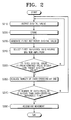
- FIG. 2 is a flowchart showing a method of measuring an ascending movement of a footstep according to an exemplary embodiment of the present invention
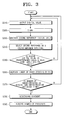
- FIG. 3 is a flowchart showing a method of measuring a descending movement of a footstep according to an exemplary embodiment of the present invention
- FIG. 4 is a block diagram illustrating an apparatus for measuring the number of footsteps according to another exemplary embodiment of the present invention.
- FIG. 5 is a flowchart showing a method of measuring the number of footsteps according to another exemplary embodiment of the present invention.
- FIG. 1 is a block diagram illustrating an apparatus for measuring the number of footsteps according to an exemplary embodiment of the present invention.
- an apparatus 100 for measuring the number of footsteps includes a terrestrial magnetism sensor 110, a memory 120, a reference digital value generator 130, a reference axis selector 140, a digital value determiner 150, a counter 160, a crossing time determiner 170, a display 180 and a controller 190.
- the terrestrial magnetism sensor 110 outputs digital values of each axis including an x-axis digital value, a y-axis digital value, and a z-axis digital value, which represent a movement of user's body in response to the controller 190.
- the terrestrial magnetism sensor 110 includes a operating pulse generating circuit 111, a current amplifying circuit 112, a three-axis fluxgate circuit 113, a chopping circuit 114, a first amplifying circuit 115, a lowpass filter 116, a second amplifying circuit 117 and an A/D converter 118.
- a two-axis fluxgate circuit may be used instead of using the three-axis fluxgate circuit 113 according to another exemplary embodiment of the present invention.
- the three-axis fluxgate circuit 113 is used for accurately detecting a movement of the user's body.
- the operating pulse generating circuit 111 generates an operating pulse to operate the three-axis fluxgate 113. After generating the operating pulse, the operating pulse generating circuit 111 selectively switches the generated operating pulse and supplies the switched operating pulse to the current amplifying circuit 112.
- the current amplifying circuit 112 generates a pulse signal and a reversed pulse signal having a reverse phase compared to the pulse signal based on the pulse output through the operating pulse generating circuit 111 by using a plurality of amplifiers and a reverser.
- the three-axis fluxgate circuit 113 includes an X-axis fluxgate, a Y-axis fluxgate and a Z-axis fluxgate which are orthogonally crossed.
- the three-axis fluxgate circuit 113 generates a detection signal in response to an electromotive force generated by magnetic field generated by the pulse signal and the reverse pulse signal transferred to the X-axis fluxgate, the Y-axis fluxgate and the Z-axis fluxgate.
- Each of the X-axis fluxgate, the Y-axis fluxgate and the Z-axis fluxgate may include two rectangular ring-shaped magnetic substance cores which are arranged in a length direction based on each of X-axis, Y-axis and Z-axis.
- a driving coil and a sensing coil are wired at each of the magnetic substance cores. If the operating pulse is applied to the driving coil, the X-axis fluxgate, the Y-axis fluxgate and the Z-axis fluxgate generate a magnetic field, and the sensing coil senses an induced electromotive force according to the generated magnetic field.
- the chopping circuit 114 chops an electric signal sensed from the three-axis fluxgate circuit 113 by using a plurality of switches.
- the first amplifying circuit 115 differentially amplifies the chopped electric signal and the lowpass filter 116 filters the chopped electric signal to generate signals within a predetermined range.
- the second amplifying circuit 117 finally amplifies the filtered signal.
- the A/D converter 118 converts the amplified signal to a digital value. That is, the A/D converter 118 outputs digital values of the X-axis, Y-axis and Z-axis in predetermined sampling time interval.
- the memory 120 stores the digital values of each axis, i.e., X-axis digital values, the Y-axis digital value, and the Z-axis digital value output from the A/D converter 118 in response to the controller 190.
- digital values corresponding to the number of footsteps among the stored digital values are defined as a target digital value.
- the reference digital value generating unit 130 generates a first reference digital value by using the stored digital value of the memory 120 such as an N digital value, a (N-1) digital value, a (N-2) digital value in response to the control of the controller 190.
- the N digital value, the (N-1) digital value and the (N-2) digital value represent digital values output from the A/D converter 118 within the sampling time interval.
- the N digital value is the target digital value.
- the reference digital value generating unit 130 generates a second reference digital value by using digital values of X-axis, Y-axis and Z-axis stored in the memory 120 such as a (N+k+1) digital value, a (N+k+2) digital value and a (N+k+3) digital value, in response to the control of the controller 190.
- the (N+k+1) digital value, the (N+k+2) digital value and the (N+k+3) digital value represent digital values output from the A/D converter 118 within the sampling time interval.
- a positive integer including 0 is applied to k and the (N+k+3) is the target digital value.
- T_RxF is a T digital value of a time T and (T-1)_RxF is a (T-1) digital value of a time (T-1) which is one sampling time before the time T. Also, the (T-2)_RxF is a (T-2) digital value of a time (T-2) which is one sampling time before the time (T-1). Furthermore, in Equation 1, "a” denotes a weight allocated at the time T, "b” represents a weight allocated at the time (T-1) and “c” denotes a weight allocated at the time (T-2). A degree that a digital value of each time influences the reference digital value is determined according to the weight. A weight higher than a previous digital value may be applied by providing b and c to be larger than a.
- the reference axis selector 140 analyzes digital values of each axis including the N digital value within a first predetermined period such as a X-axis digital value (N x digital value), a Y-axis digital value (N y digital value) and a Z-axis digital value (N z digital value) in response to the controller 190.
- N x digital value a X-axis digital value
- N y digital value a Y-axis digital value
- N z digital value Z-axis digital value
- the reference axis selector 140 also analyzes digital values of each axis including the (N+k+3) digital value within a second predetermined period such as a X-axis digital value ((N+k+3) x digital value), a Y-axis digital value ((N+k+3) y digital value) and a Z-axis digital value ((N+k+3) z digital value) in response to the controller 190.
- the first predetermined period and the second predetermined period may be optimally set by simulations.
- the reference axis selector 140 searches a maximum value and a minimum value in the digital values of each axis.
- the reference axis selector 140 selects a reference axis having a maximum amplitude among the X-axis digital value, the Y-axis digital value and the Z-axis digital value.
- a reference axis corresponding to the N digital value is defined as a first reference axis and a reference axis corresponding to the (N+k+3) digital value is defined as a second reference axis.
- the digital value determiner 150 compares a reference digital value corresponding to the first reference axis and an N digital value corresponding to the first reference axis in response to the controller 190. If the first reference digital value is larger than the N digital value as much as a first predetermined value, the controller 190 indicates that an over-crossing has occurred.
- the term "over-crossing" means that a target digital value is larger than the reference digital value by a predetermined value.
- the first predetermined value is a value set by applying various experimental noises.
- the digital value determiner 150 compares a second reference digital value corresponding to the second reference axis and a (N+k+3) digital value corresponding to the second reference axis in response to the controller 190 after detecting an ascending movement of one footstep. If the second reference digital value is larger than the (N+k+3) digital value by a second predetermined value, the controller 190 indicates that an under-crossing has occurred.
- under-crossing means that the target digital value is smaller than the reference digital value by a predetermined value.
- the second predetermined value is also set by applying experimental various noises.
- the counter 160 increases the number of over-crossing by one when the over-crossing has occurred in response to the controller 190.
- the counter 160 also increases the number of under-crossing by one when the under-crossing has occurred in response to the controller 190.
- the counter 160 also increase the number of footsteps by one when the ascending movement and the descending movement of one footstep are detected.
- the crossing time determiner 170 determines whether the number of the over-crossing counted by the counter 160 is larger than a reference over-crossing time in response to the controller 190.
- the reference over-crossing time is set by applying various experimental noises.
- the reference over-crossing time may be 2, for example. If the increased over-crossing time is larger than the reference over-crossing time, the controller 190 determines that a body movement of a user is an ascending movement of one footstep.
- the crossing time determiner 170 also determines whether the number of the under-crossing counted by the counter 160 is larger than a reference under-crossing time in response to the controller 190.
- the reference under-crossing time is set by applying various experimental noises.
- the reference under-crossing time may be 3, for example. If the increased over-crossing time is larger than the reference under-crossing time, the controller 190 determines that a body movement of a user is a descending movement of one footstep.
- the display 180 displays the increased number of footsteps in response to the controller 190 when the counter 160 increases the number of footsteps by one.
- the controller 190 generally controls the apparatus 100 for measuring the number of footsteps according to a control program stored in the memory 120.
- FIG. 2 is a flowchart showing a method of measuring the number of footsteps according to an exemplary embodiment of the present invention. Especially, the flowchart of FIG. 2 shows a method of measuring an ascending movement in the apparatus 100 shown in FIG. 1.
- the terrestrial magnetism sensor 110 detects a (N-2) digital value at operation S210 and the output (N-2) digital value is stored at the memory 120 at operation S220.
- the terrestrial magnetism sensor 110 also detects a (N-1) digital value after one sampling time is elapsed after the (N-2) digital value is output at operation S210 and the output (N-1) digital value is stored in the memory 120 at operation S220.
- the terrestrial magnetism sensor 110 further detects an N digital value after one sampling time is elapsed after the (N-1) digital value is detected at operation S210 and the output N digital value is stored in the memory 120 at operation S220.
- the digital value generator 130 By using the stored (N-2) to N digital values, the digital value generator 130 generates a first reference digital value at operation S230.
- the first reference digital value may be generated according to Equation 1.
- the reference axis selector 140 analyzes an X-axis digital value (N x digital value), a Y-axis digital value (N y digital value) and a Z-axis digital value (N z digital value) including the N digital value within a first predetermined period and selects a first reference axis having a maximum amplitude by finding a maximum value and a minimum value at operation S240.
- the first reference axis having the maximum amplitude is assumed as an X-axis.
- the digital value determiner 150 compares the first reference digital value of the X axis and the N x digital value of the X axis at operation S250.
- the N x digital value is an N digital value of the X-axis and it may be represented as a target digital value.
- the operations S210 to S250 are repeatedly performed.
- the counter increases the number of over-crossing by one at operation S260.
- the crossing time determiner 170 determines whether the increased over-crossing time is larger than an over-crossing reference time at operation S270.
- the controller 190 determines that a movement of the user is an ascending movement of one footstep at operation S280.
- the operations S210 to S270 are repeatedly performed in response to the controller 190.
- FIG. 3 is a flowchart showing a method of measuring a descending movement in the apparatus shown in FIG. 1.
- the terrestrial magnetism sensor 110 outputs a (N+k) digital value and a (N+k+1) digital value after one sampling time is elapsed after the (N+k) digital value is output at operation S310 and the output (N+k+1) digital value is stored in the memory 120 at operation S320.
- the terrestrial magnetism sensor 110 outputs a (N+k+2) digital value after one sampling time is elapsed after the (N+k+1) digital value is output at operation S310 and the output (N+k+2) digital value is stored in the memory 120 at operation S320.
- a (N+k+3) digital value is output at operation S310 and the output (N+k+3) digital value is stored in the memory 120 at operation S320.
- the digital value generator 130 By using the stored (N+k+1) to (N+k+3) digital values, the digital value generator 130 generates a second reference digital value at operation S330.
- the reference axis selector 140 analyzes an X-axis digital value ((N+k+3) x digital value), a Y-axis digital value ((N+k+3) y digital value) and a Z-axis digital value ((N+k+3) z digital value) including the (N+k+3) digital value within a second predetermined period and selects a second reference axis having a maximum amplitude by finding a maximum value and a minimum value at operation S340.
- the first reference axis having the maximum amplitude is assumed to be a Y-axis.
- the digital value determiner 150 compares the second reference digital value of the Y axis and the (N+k+3) y digital value of the Y axis at operation S350.
- the (N+k+3) y digital value is an (N+k+3) digital value for the Y-axis and it may be represented as a target digital value.
- the operations S310 to S350 are repeatedly performed in response to the controller 190.
- the counter increases the number of under-crossing by one at operation S360.
- the crossing time determiner 170 determines whether the increased under-crossing time is larger than an under-crossing reference time at operation S370.
- the controller 190 determines that a movement of the user is a descending movement of one footstep at operation S380.
- the counter 160 also increases the number of footsteps by one at operation S390.
- the operations S310 to S370 are repeatedly performed in response to the controller 190.
- FIG. 4 is a block diagram illustrating an apparatus for measuring the number of footsteps according to another exemplary embodiment of the present invention.
- An apparatus 400 for measuring the number of footsteps according to another exemplary embodiment shown in FIG. 4 has elements similar to the apparatus 100 show in FIG. 1. Therefore, explanation of the similar elements of the apparatus 400 will be omitted to simplify the description of this embodiment.
- the apparatus 400 for measuring the number of footsteps includes a terrestrial magnetism sensor 410, a memory 420, a subtracter 430, an adder 440, a determiner 450, a counter 460, a display 470 and a controller 480.
- the terrestrial magnetism sensor 410 and the memory 420 perform similar functions of the terrestrial magnetism sensor 110 and the memory 120 shown in FIG. 1.
- the terrestrial magnetism sensor 410 outputs (M-1) digital values of each axis, such as an X-axis (M-1) digital value ((M-1) x digital value), a Y-axis (M-1) digital value ((M-1) Y digital value) and a Z-axis (M-1) digital value ((M-1) z digital value).
- the terrestrial magnetism sensor 410 After elapsing one sampling time interval after the (M-1) digital values are output, the terrestrial magnetism sensor 410 outputs M digital values of each axis such as an X-axis M digital value (M x digital value), a Y-axis M digital value (M Y digital value) and a Z-axis M digital value (M z digital value).
- M x digital value an X-axis M digital value
- M Y digital value Y-axis M digital value
- M z digital value Z-axis M digital value
- the subtracter 430 subtracts the (M-1) digital values from the M digital values according to each axis and calculates difference values of each axis ( ⁇ X, ⁇ Y, ⁇ Z) based on the subtraction results.
- the adder 440 adds the difference values of each axis ( ⁇ X, ⁇ Y, ⁇ Z) and outputs a sum of the difference values.
- the determiner 450 determines whether a zero-crossing has occurred, where the zero-crossing represents that the sum is transferred from a positive value to a negative value or vice versa. If the zero-crossing has occurred, the controller 480 determines that a movement of the user is a half of one footstep.
- the counter 460 increases the number of zero-crossing by one when the zero-crossing has occurred.
- the counter 460 increases the number of footsteps by one when the number of the zero-crossing is 2.
- the counter 460 is initialized by the controller 480 when the number of the zero-crossing is 2.
- the display 470 displays the increased number of footsteps when the counter 460 increases the number of footsteps by one.
- the controller 480 determines whether the increased number of zero-crossing is 2. If the increased number of zero-crossing is 2, the controller 480 determines that the movement of the user is one footstep.
- FIG. 5 is a flowchart showing a method of measuring the number of footsteps according to another exemplary embodiment of the present invention.
- (M-1) digital values of each axis are generated at operation S510. That is, the terrestrial magnetism sensor 410 generates an X-axis (M-1) digital value ((M-1) x digital value), a Y-axis (M-1) digital value ((M-1) Y digital value) and a Z-axis (M-1) digital value ((M-1) z digital value) at operation S510. And, the output (M-1) digital values of each axis are stored in the memory 420 at operation S520.
- M digital values of each axis such as an X-axis M digital value (M x digital value), a Y-axis M digital value (M y digital value) and a Z-axis M digital value (M z digital value) are output at operation S510 and the output M digital values are stored in the memory 420 at operation S520.
- the subtracter 430 calculates difference values of each axis ( ⁇ X, ⁇ Y, ⁇ Z) by subtracting the (M-1) digital values of each axis from the M digital values of each axis at operation S530.
- the adder 440 adds the calculated difference values ( ⁇ X, ⁇ Y, ⁇ Z) to output a sum of the difference values at operation S540.
- the determiner 450 determines whether a zero-crossing has occurred at operation S550. That is, the determiner 450 determines whether the sum digital value is transferred from a positive value to a negative value or vice versa at operation S550.
- the controller 480 determines that the movement of the user is a half of one footstep and the counter 460 increases the number of zero-crossing by one in response to the controller 480 at operation S560.
- the controller 480 determines whether the increased number of zero-crossing is 2 at operation S570. If the increased number of zero-crossing is 2, the controller 480 determines that the movement of the user is one footstep at operation S580. The controller 480 increases the number of the footsteps by one. Meanwhile, the controller 480 initializes the number of the zero-crossing in the counter 460.
- controller 480 repeatedly performs the operations 510 through 570.
- a user may wear the apparatus 100 or 400 on the user's arm. This is because the terrestrial magnetism sensor 110 or 410 can generate a digital value according to a rotation angle formed by rotating the arm about the user's shoulder.
- the user may wear the apparatus 100 or 400 on the user's leg. This is because the terrestrial magnetism sensor 110 or 410 can generate a digital value according to a rotation angle made by rotating the leg about a pelvis.
- the terrestrial magnetism sensor is used for measuring the number of footsteps instead of using an acceleration sensor. Accordingly, the apparatus for measuring the number of footsteps using the terrestrial magnetism sensor according to the present exemplary embodiments consumes less electric power that a conventional apparatus for measuring the number of footsteps using the acceleration sensor. Therefore, the apparatus according to the present exemplary embodiments may be used longer than the conventional apparatus with a limited power source. Furthermore, the number of footsteps may be measured by considering noise in the present exemplary embodiments. Therefore, the number of footsteps may be precisely measured.
Landscapes
- Health & Medical Sciences (AREA)
- Life Sciences & Earth Sciences (AREA)
- Engineering & Computer Science (AREA)
- Physics & Mathematics (AREA)
- Remote Sensing (AREA)
- Radar, Positioning & Navigation (AREA)
- General Physics & Mathematics (AREA)
- Biophysics (AREA)
- Public Health (AREA)
- Biomedical Technology (AREA)
- Heart & Thoracic Surgery (AREA)
- Medical Informatics (AREA)
- Molecular Biology (AREA)
- Surgery (AREA)
- Animal Behavior & Ethology (AREA)
- General Health & Medical Sciences (AREA)
- Pathology (AREA)
- Veterinary Medicine (AREA)
- Oral & Maxillofacial Surgery (AREA)
- Dentistry (AREA)
- Physiology (AREA)
- Measurement Of The Respiration, Hearing Ability, Form, And Blood Characteristics Of Living Organisms (AREA)
- Measurement Of Distances Traversed On The Ground (AREA)
- Indicating And Signalling Devices For Elevators (AREA)
- Examining Or Testing Airtightness (AREA)
- Measuring Magnetic Variables (AREA)
Abstract
Description
- This application claims priority from Korean Patent Application No. 2004-94963, filed on November 19, 2004, in the Korean Intellectual Property Office, the entire disclosure of which is incorporated herein by reference.
- Apparatuses and methods consistent with the present invention relate to measuring a number of footsteps; more particularly, to measuring the number of footsteps using a terrestrial magnetism sensor.
- According to a growing interest in promoting health, footstep measuring apparatuses have been introduced and actively developed. For example, a handheld phone has been introduced that includes a function of measuring the number of footsteps, which has become very popular among people who want to preserve their health.
- Conventional footstep measuring apparatuses generally use an acceleration sensor to measure the number of footsteps, and because of the acceleration sensor, the conventional footstep measuring apparatus consumes relatively large quantity of electric power.
- Footstep measuring apparatuses are generally embedded in a small sized electric appliance such as a handheld phone. However, it is not preferable to embed the acceleration sensor, which consumes mass amounts of electric power, in such a small sized electric appliance having a limited electric power source.
- An aspect of the present general inventive concept is to provide an apparatus and method for measuring the number of footsteps using a terrestrial magnetism.
- It is another aspect of the present invention to provide an apparatus and method for measuring the number of footsteps by calculating a predetermined weight applied reference digital value and detecting an ascending movement and a descending movement of one footstep through comparing the reference digital value and a digital value of a target object.
- It is still another aspect of the present invention to provide an apparatus and method for measuring the number of footsteps by subtracting previous digital values of each axis from current digital values of each axis, adding the subtracting results of each axis and determining a half of one footstep when a sign of the adding result is changed.
- In accordance with an aspect of the present invention, there is provided an apparatus for measuring the number of footsteps, including: a terrestrial magnetism sensing unit for outputting digital values of each axis with a predetermined sampling time interval by using at least two axis of terrestrial magnetism sensors among a X-axis, a Y-axis and a Z-axis according to movements of a body; a reference digital value generator for generating a reference digital value based on N digital values of each axis output from the terrestrial magnetism sensing unit, (N-1) digital values of each axis output from the terrestrial magnetism sensing unit in one sampling time interval before the N digital values are output, (N-2) digital values of each axis output from the terrestrial magnetism sensor in one sampling time interval before the (N-1) digital values output; a reference axis selector for searching N digital value of one axis having a maximum amplitude in a predetermined period among the N digital values of each axis and selecting the one axis having the maximum amplitude as a reference axis; a digital value determiner for determining whether the N digital value of the selected reference axis is larger than a reference digital value of the selected reference axis as much as a predetermined value; and a controller for determining the movement of the body as an ascending movement of one footstep when the N digital value is larger than the reference digital value as much as a predetermined value.
- The reference digital value generator may generate the reference digital value (Ref_Value) based on an equation as:

- The controller may determine that the movement of the body is a descending movement of one footstep when the digital value determiner determines that the N digital value of the reference axis is smaller than the reference digital value of the reference axis as much as a predetermined value.
- The apparatus may further include a counter for increasing the number of footsteps by one when the controller determines the descending movement.
- The apparatus may further include a display which displays the number of footsteps counted by the counter in response to the controller.
- In accordance with another aspect of the present invention, there is provided an apparatus for measuring the number of footsteps including: a terrestrial magnetism sensing unit for outputting digital values of each axis within a predetermined sampling time by using at least two axis of terrestrial magnetism sensor among a X-axis, a Y-axis and a Z-axis according to movements of a body; a subtracter for generating difference digital values of each axis by subtracting (N-1) digital values of each axis, which are output in one sampling time before outputting N digital values of each axis from the terrestrial magnetism sensing unit, from the N digital values of each axis; an adder for generating a sum digital value by adding the difference values of each axis; and a controller for determining that the movement of the user is a half of one footstep when a sign of the sum digital value is changed.
- The controller may determine that the movement of the body is another half of one footstep when the changed sign of the sum digital value is changed again.
- The apparatus may further include a counter for increasing the number of footsteps by one when the controller determines that the movement of the body is another half of one step.
- The apparatus may further include a display which displays the number of footsteps counted by the counter in response to the controller.
- In accordance with still another aspect of the present invention, there is provided a method of measuring the number of footsteps, including : outputting digital values of each axis within a predetermined sampling time interval by using at least two-axis of terrestrial magnetism sensor among a X-axis, a Y-axis and a Z-axis according to movements of a body; generating a reference digital value based on N digital values of each axis, (N-1) digital values of each axis output in one sampling time before outputting the Nth digital values, (N-2) digital values of each axis output in one sampling time before outputting the (N-1) digital values; searching an N digital value of one axis having a maximum amplitude in a predetermined period among the N digital values of each axis and selecting the one axis as a reference axis; determining whether the N digital value of the selected reference axis is larger than a reference digital value of the selected reference axis as much as a predetermined value; and determining the movement of the body as an ascending movement of one footstep when the N digital value is larger than the reference digital value as much as a predetermined value.
- In generating the reference digital value, the reference digital value (Ref_Value) may be generated based on an equation as Ref_Value=a×N_R×F+b×(N-1)_R×F+c×(N-2)_RxF , where N RxF is an N digital value, (N-1)_RxF is a (N-1) digital value, the (N-2)_RxF is a (N-2) digital value, a denotes a weight allocated at an N sampling point, b represents a weight allocated at the (N-1) sampling point and c denotes a weight allocated at the (N-2) sampling point.
- The method may further include: determining that the movement of the body is a descending movement of one footstep when the digital value determiner determines when the N digital value of the reference axis is a predetermined value smaller than the reference digital value of the reference axis.
- The method may further include: increasing the number of footsteps by one when the controller determines the descending movement.
- The method may further include: displaying the number of footsteps counted by the counter in response to the controller.
- In accordance with further still another aspect of the present invention, there is provided a method for measuring the number of footsteps, including: outputting digital values of each axis within a predetermined sampling time interval by using at least two axis of terrestrial magnetism sensor among a X-axis, a Y-axis and a Z-axis according to movements of a body; generating difference digital values of each axis by subtracting (N-1) digital values of each axis, which are output in one sampling time before outputting N digital values of each axis, from the Nth digital values of each axis; generating a sum digital value by adding the difference values of each axis; and determining that the movement of the user is a half of one footstep when a sign of the sum digital value is changed.
- The method may further include determining that the movement of the body is another half of one footstep when the changed sign of the sum digital value is changed again.
- The method may further include: increasing the number of footsteps by one when the controller determines that the movement of the body is another half of one step.
- The method may further include: displaying the number of footsteps counted by the counter in response to the controller.
- The above and/or other aspects of the present invention will be more apparent by describing certain exemplary embodiments of the present invention with reference to the accompanying drawings, in which:
- FIG. 1 is a block diagram illustrating an apparatus for measuring the number of footsteps according to an exemplary embodiment of the present invention;
- FIG. 2 is a flowchart showing a method of measuring an ascending movement of a footstep according to an exemplary embodiment of the present invention;
- FIG. 3 is a flowchart showing a method of measuring a descending movement of a footstep according to an exemplary embodiment of the present invention;
- FIG. 4 is a block diagram illustrating an apparatus for measuring the number of footsteps according to another exemplary embodiment of the present invention; and
- FIG. 5 is a flowchart showing a method of measuring the number of footsteps according to another exemplary embodiment of the present invention.
- Exemplary embodiments of the present invention will be described in greater detail with reference to the accompanying drawings.
- In the following description, same drawing reference numerals are used for the same elements even in different drawings. FIG. 1 is a block diagram illustrating an apparatus for measuring the number of footsteps according to an exemplary embodiment of the present invention.
- Referring to FIG. 1, an
apparatus 100 for measuring the number of footsteps includes aterrestrial magnetism sensor 110, amemory 120, a referencedigital value generator 130, areference axis selector 140, a digital value determiner 150, acounter 160, a crossing time determiner 170, adisplay 180 and acontroller 190. - The
terrestrial magnetism sensor 110 outputs digital values of each axis including an x-axis digital value, a y-axis digital value, and a z-axis digital value, which represent a movement of user's body in response to thecontroller 190. - The
terrestrial magnetism sensor 110 according to the present embodiment includes a operatingpulse generating circuit 111, a current amplifyingcircuit 112, a three-axis fluxgate circuit 113, achopping circuit 114, a first amplifyingcircuit 115, alowpass filter 116, a second amplifyingcircuit 117 and an A/D converter 118. A two-axis fluxgate circuit may be used instead of using the three-axis fluxgate circuit 113 according to another exemplary embodiment of the present invention. However, in the present exemplary embodiment, the three-axis fluxgate circuit 113 is used for accurately detecting a movement of the user's body. - The operating
pulse generating circuit 111 generates an operating pulse to operate the three-axis fluxgate 113. After generating the operating pulse, the operatingpulse generating circuit 111 selectively switches the generated operating pulse and supplies the switched operating pulse to the current amplifyingcircuit 112. - The current amplifying
circuit 112 generates a pulse signal and a reversed pulse signal having a reverse phase compared to the pulse signal based on the pulse output through the operatingpulse generating circuit 111 by using a plurality of amplifiers and a reverser. - The three-
axis fluxgate circuit 113 includes an X-axis fluxgate, a Y-axis fluxgate and a Z-axis fluxgate which are orthogonally crossed. The three-axis fluxgate circuit 113 generates a detection signal in response to an electromotive force generated by magnetic field generated by the pulse signal and the reverse pulse signal transferred to the X-axis fluxgate, the Y-axis fluxgate and the Z-axis fluxgate. Each of the X-axis fluxgate, the Y-axis fluxgate and the Z-axis fluxgate may include two rectangular ring-shaped magnetic substance cores which are arranged in a length direction based on each of X-axis, Y-axis and Z-axis. A driving coil and a sensing coil are wired at each of the magnetic substance cores. If the operating pulse is applied to the driving coil, the X-axis fluxgate, the Y-axis fluxgate and the Z-axis fluxgate generate a magnetic field, and the sensing coil senses an induced electromotive force according to the generated magnetic field. - The
chopping circuit 114 chops an electric signal sensed from the three-axis fluxgate circuit 113 by using a plurality of switches. The first amplifyingcircuit 115 differentially amplifies the chopped electric signal and thelowpass filter 116 filters the chopped electric signal to generate signals within a predetermined range. The second amplifyingcircuit 117 finally amplifies the filtered signal. The A/D converter 118 converts the amplified signal to a digital value. That is, the A/D converter 118 outputs digital values of the X-axis, Y-axis and Z-axis in predetermined sampling time interval. - The
memory 120 stores the digital values of each axis, i.e., X-axis digital values, the Y-axis digital value, and the Z-axis digital value output from the A/D converter 118 in response to thecontroller 190. - Hereinafter, digital values corresponding to the number of footsteps among the stored digital values are defined as a target digital value.
- The reference digital
value generating unit 130 generates a first reference digital value by using the stored digital value of thememory 120 such as an N digital value, a (N-1) digital value, a (N-2) digital value in response to the control of thecontroller 190. The N digital value, the (N-1) digital value and the (N-2) digital value represent digital values output from the A/D converter 118 within the sampling time interval. Among the output digital values, the N digital value is the target digital value. - The reference digital
value generating unit 130 generates a second reference digital value by using digital values of X-axis, Y-axis and Z-axis stored in thememory 120 such as a (N+k+1) digital value, a (N+k+2) digital value and a (N+k+3) digital value, in response to the control of thecontroller 190. The (N+k+1) digital value, the (N+k+2) digital value and the (N+k+3) digital value represent digital values output from the A/D converter 118 within the sampling time interval. Also, a positive integer including 0 is applied to k and the (N+k+3) is the target digital value. - The reference digital
value generating unit 130 may calculate the first reference digital value and the second reference digital value (Ref_Value) according to Equation 1, as follows:
- In Equation 1, T_RxF is a T digital value of a time T and (T-1)_RxF is a (T-1) digital value of a time (T-1) which is one sampling time before the time T. Also, the (T-2)_RxF is a (T-2) digital value of a time (T-2) which is one sampling time before the time (T-1). Furthermore, in Equation 1, "a" denotes a weight allocated at the time T, "b" represents a weight allocated at the time (T-1) and "c" denotes a weight allocated at the time (T-2). A degree that a digital value of each time influences the reference digital value is determined according to the weight. A weight higher than a previous digital value may be applied by providing b and c to be larger than a.
- The
reference axis selector 140 analyzes digital values of each axis including the N digital value within a first predetermined period such as a X-axis digital value (Nx digital value), a Y-axis digital value (Ny digital value) and a Z-axis digital value (Nz digital value) in response to thecontroller 190. Thereference axis selector 140 also analyzes digital values of each axis including the (N+k+3) digital value within a second predetermined period such as a X-axis digital value ((N+k+3)x digital value), a Y-axis digital value ((N+k+3)y digital value) and a Z-axis digital value ((N+k+3)z digital value) in response to thecontroller 190. The first predetermined period and the second predetermined period may be optimally set by simulations. - The
reference axis selector 140 searches a maximum value and a minimum value in the digital values of each axis. Thereference axis selector 140 selects a reference axis having a maximum amplitude among the X-axis digital value, the Y-axis digital value and the Z-axis digital value. Hereinafter, a reference axis corresponding to the N digital value is defined as a first reference axis and a reference axis corresponding to the (N+k+3) digital value is defined as a second reference axis. - The
digital value determiner 150 compares a reference digital value corresponding to the first reference axis and an N digital value corresponding to the first reference axis in response to thecontroller 190. If the first reference digital value is larger than the N digital value as much as a first predetermined value, thecontroller 190 indicates that an over-crossing has occurred. The term "over-crossing" means that a target digital value is larger than the reference digital value by a predetermined value. The first predetermined value is a value set by applying various experimental noises. - The
digital value determiner 150 compares a second reference digital value corresponding to the second reference axis and a (N+k+3) digital value corresponding to the second reference axis in response to thecontroller 190 after detecting an ascending movement of one footstep. If the second reference digital value is larger than the (N+k+3) digital value by a second predetermined value, thecontroller 190 indicates that an under-crossing has occurred. The term "under-crossing" means that the target digital value is smaller than the reference digital value by a predetermined value. The second predetermined value is also set by applying experimental various noises. - The
counter 160 increases the number of over-crossing by one when the over-crossing has occurred in response to thecontroller 190. Thecounter 160 also increases the number of under-crossing by one when the under-crossing has occurred in response to thecontroller 190. - The
counter 160 also increase the number of footsteps by one when the ascending movement and the descending movement of one footstep are detected. - The
crossing time determiner 170 determines whether the number of the over-crossing counted by thecounter 160 is larger than a reference over-crossing time in response to thecontroller 190. The reference over-crossing time is set by applying various experimental noises. The reference over-crossing time may be 2, for example. If the increased over-crossing time is larger than the reference over-crossing time, thecontroller 190 determines that a body movement of a user is an ascending movement of one footstep. - The
crossing time determiner 170 also determines whether the number of the under-crossing counted by thecounter 160 is larger than a reference under-crossing time in response to thecontroller 190. The reference under-crossing time is set by applying various experimental noises. The reference under-crossing time may be 3, for example. If the increased over-crossing time is larger than the reference under-crossing time, thecontroller 190 determines that a body movement of a user is a descending movement of one footstep. - The
display 180 displays the increased number of footsteps in response to thecontroller 190 when thecounter 160 increases the number of footsteps by one. - The
controller 190 generally controls theapparatus 100 for measuring the number of footsteps according to a control program stored in thememory 120. - FIG. 2 is a flowchart showing a method of measuring the number of footsteps according to an exemplary embodiment of the present invention. Especially, the flowchart of FIG. 2 shows a method of measuring an ascending movement in the
apparatus 100 shown in FIG. 1. - Referring to FIGS. 1 and 2, if a user moves after the user wears the
apparatus 100 for measuring the number of footsteps, theterrestrial magnetism sensor 110 detects a (N-2) digital value at operation S210 and the output (N-2) digital value is stored at thememory 120 at operation S220. Theterrestrial magnetism sensor 110 also detects a (N-1) digital value after one sampling time is elapsed after the (N-2) digital value is output at operation S210 and the output (N-1) digital value is stored in thememory 120 at operation S220. Theterrestrial magnetism sensor 110 further detects an N digital value after one sampling time is elapsed after the (N-1) digital value is detected at operation S210 and the output N digital value is stored in thememory 120 at operation S220. - By using the stored (N-2) to N digital values, the
digital value generator 130 generates a first reference digital value at operation S230. The first reference digital value may be generated according to Equation 1. - The
reference axis selector 140 analyzes an X-axis digital value (Nx digital value), a Y-axis digital value (Ny digital value) and a Z-axis digital value (Nz digital value) including the N digital value within a first predetermined period and selects a first reference axis having a maximum amplitude by finding a maximum value and a minimum value at operation S240. - Hereinafter, the first reference axis having the maximum amplitude is assumed as an X-axis.
- The
digital value determiner 150 compares the first reference digital value of the X axis and the Nx digital value of the X axis at operation S250. The Nx digital value is an N digital value of the X-axis and it may be represented as a target digital value. - If the first reference digital value is not larger than the Nx digital value by a first predetermined value at operation S250, the operations S210 to S250 are repeatedly performed.
- If the first reference digital value is larger than the Nx digital value by a first predetermined value at operation S250, the counter increases the number of over-crossing by one at operation S260.
- After increasing, the
crossing time determiner 170 determines whether the increased over-crossing time is larger than an over-crossing reference time at operation S270. - If the increased over-crossing time is larger than the over-crossing reference time at operation S270, the
controller 190 determines that a movement of the user is an ascending movement of one footstep at operation S280. - If the increased over-crossing time is smaller than the over-crossing reference time at operation S270, the operations S210 to S270 are repeatedly performed in response to the
controller 190. - FIG. 3 is a flowchart showing a method of measuring a descending movement in the apparatus shown in FIG. 1.
- Referring to FIGS. 1 and 3, if the user continuously moves after the ascending movement of the user is detected, the
terrestrial magnetism sensor 110 outputs a (N+k) digital value and a (N+k+1) digital value after one sampling time is elapsed after the (N+k) digital value is output at operation S310 and the output (N+k+1) digital value is stored in thememory 120 at operation S320. Theterrestrial magnetism sensor 110 outputs a (N+k+2) digital value after one sampling time is elapsed after the (N+k+1) digital value is output at operation S310 and the output (N+k+2) digital value is stored in thememory 120 at operation S320. After one sampling time is elapsed after the (N+k+1) digital value is output, a (N+k+3) digital value is output at operation S310 and the output (N+k+3) digital value is stored in thememory 120 at operation S320. - By using the stored (N+k+1) to (N+k+3) digital values, the
digital value generator 130 generates a second reference digital value at operation S330. - The
reference axis selector 140 analyzes an X-axis digital value ((N+k+3)x digital value), a Y-axis digital value ((N+k+3)y digital value) and a Z-axis digital value ((N+k+3)z digital value) including the (N+k+3) digital value within a second predetermined period and selects a second reference axis having a maximum amplitude by finding a maximum value and a minimum value at operation S340. - Hereinafter, the first reference axis having the maximum amplitude is assumed to be a Y-axis.
- The
digital value determiner 150 compares the second reference digital value of the Y axis and the (N+k+3)y digital value of the Y axis at operation S350. The (N+k+3)y digital value is an (N+k+3) digital value for the Y-axis and it may be represented as a target digital value. - If the second reference digital value is not smaller than the (N+k+3)y digital value by a second predetermined value at operation S350, the operations S310 to S350 are repeatedly performed in response to the
controller 190. - If the second reference digital value is smaller than the (N+k+3)y digital value by a second predetermined value at operation S350, the counter increases the number of under-crossing by one at operation S360.
- After increasing, the
crossing time determiner 170 determines whether the increased under-crossing time is larger than an under-crossing reference time at operation S370. - If the increased over-crossing time is larger than the under-crossing reference time at operation S370, the
controller 190 determines that a movement of the user is a descending movement of one footstep at operation S380. Thecounter 160 also increases the number of footsteps by one at operation S390. - If the increased under-crossing time is smaller than the under-crossing reference time at operation S370, the operations S310 to S370 are repeatedly performed in response to the
controller 190. - FIG. 4 is a block diagram illustrating an apparatus for measuring the number of footsteps according to another exemplary embodiment of the present invention.
- An
apparatus 400 for measuring the number of footsteps according to another exemplary embodiment shown in FIG. 4 has elements similar to theapparatus 100 show in FIG. 1. Therefore, explanation of the similar elements of theapparatus 400 will be omitted to simplify the description of this embodiment. - Referring to FIG. 4, the
apparatus 400 for measuring the number of footsteps according to another exemplary embodiment includes aterrestrial magnetism sensor 410, amemory 420, asubtracter 430, anadder 440, adeterminer 450, acounter 460, adisplay 470 and acontroller 480. - The
terrestrial magnetism sensor 410 and thememory 420 perform similar functions of theterrestrial magnetism sensor 110 and thememory 120 shown in FIG. 1. Theterrestrial magnetism sensor 410 outputs (M-1) digital values of each axis, such as an X-axis (M-1) digital value ((M-1)x digital value), a Y-axis (M-1) digital value ((M-1)Y digital value) and a Z-axis (M-1) digital value ((M-1)z digital value). After elapsing one sampling time interval after the (M-1) digital values are output, theterrestrial magnetism sensor 410 outputs M digital values of each axis such as an X-axis M digital value (Mx digital value), a Y-axis M digital value (MY digital value) and a Z-axis M digital value (Mz digital value). The (M-1) digital values and the M digital values are stored in thememory 420 in response to thecontroller 480. - The
subtracter 430 subtracts the (M-1) digital values from the M digital values according to each axis and calculates difference values of each axis (ΔX, ΔY, ΔZ) based on the subtraction results. - The
adder 440 adds the difference values of each axis (ΔX, ΔY, ΔZ) and outputs a sum of the difference values. - The
determiner 450 determines whether a zero-crossing has occurred, where the zero-crossing represents that the sum is transferred from a positive value to a negative value or vice versa. If the zero-crossing has occurred, thecontroller 480 determines that a movement of the user is a half of one footstep. - The
counter 460 increases the number of zero-crossing by one when the zero-crossing has occurred. Thecounter 460 increases the number of footsteps by one when the number of the zero-crossing is 2. Meanwhile, thecounter 460 is initialized by thecontroller 480 when the number of the zero-crossing is 2. - The
display 470 displays the increased number of footsteps when thecounter 460 increases the number of footsteps by one. - The
controller 480 determines whether the increased number of zero-crossing is 2. If the increased number of zero-crossing is 2, thecontroller 480 determines that the movement of the user is one footstep. - FIG. 5 is a flowchart showing a method of measuring the number of footsteps according to another exemplary embodiment of the present invention.
- Referring to FIGS. 4 and 5, if a user moves after the user wears or equips the
apparatus 400, (M-1) digital values of each axis are generated at operation S510. That is, theterrestrial magnetism sensor 410 generates an X-axis (M-1) digital value ((M-1)x digital value), a Y-axis (M-1) digital value ((M-1)Y digital value) and a Z-axis (M-1) digital value ((M-1)z digital value) at operation S510. And, the output (M-1) digital values of each axis are stored in thememory 420 at operation S520. After outputting the (M-1) digital values and elapsing one sampling time, M digital values of each axis such as an X-axis M digital value (Mx digital value), a Y-axis M digital value (My digital value) and a Z-axis M digital value (Mz digital value) are output at operation S510 and the output M digital values are stored in thememory 420 at operation S520. - The
subtracter 430 calculates difference values of each axis (ΔX, ΔY, ΔZ) by subtracting the (M-1) digital values of each axis from the M digital values of each axis at operation S530. - The
adder 440 adds the calculated difference values (ΔX, ΔY, ΔZ) to output a sum of the difference values at operation S540. - The
determiner 450 determines whether a zero-crossing has occurred at operation S550. That is, thedeterminer 450 determines whether the sum digital value is transferred from a positive value to a negative value or vice versa at operation S550. - If the zero-crossing has occurred at operation S550, the
controller 480 determines that the movement of the user is a half of one footstep and thecounter 460 increases the number of zero-crossing by one in response to thecontroller 480 at operation S560. - The
controller 480 determines whether the increased number of zero-crossing is 2 at operation S570. If the increased number of zero-crossing is 2, thecontroller 480 determines that the movement of the user is one footstep at operation S580. Thecontroller 480 increases the number of the footsteps by one. Meanwhile, thecontroller 480 initializes the number of the zero-crossing in thecounter 460. - If the zero-crossing has not occurred, the
controller 480 repeatedly performs the operations 510 through 570. - According to the present exemplary embodiments, a user may wear the
apparatus terrestrial magnetism sensor - Also, according to the present exemplary embodiments, the user may wear the
apparatus terrestrial magnetism sensor - As described above, in the present exemplary embodiments, the terrestrial magnetism sensor is used for measuring the number of footsteps instead of using an acceleration sensor. Accordingly, the apparatus for measuring the number of footsteps using the terrestrial magnetism sensor according to the present exemplary embodiments consumes less electric power that a conventional apparatus for measuring the number of footsteps using the acceleration sensor. Therefore, the apparatus according to the present exemplary embodiments may be used longer than the conventional apparatus with a limited power source. Furthermore, the number of footsteps may be measured by considering noise in the present exemplary embodiments. Therefore, the number of footsteps may be precisely measured.
- The foregoing embodiments are merely exemplary and are not to be construed as limiting the present invention. The present teachings can be readily applied to other types of apparatuses. Also, the description of the exemplary embodiments of the present invention is intended to be illustrative, and not to limit the scope of the claims, and many alternatives, modifications, and variations will be apparent to those skilled in the art.
Claims (18)
- An apparatus for measuring a number of footsteps, the apparatus comprising:a terrestrial magnetism sensing unit which outputs digital values of at least two of an X-axis, a Y-axis and a Z-axis, within a predetermined sampling time interval according to movement of a body;a reference digital value generator which generates a reference digital value based on N digital values of each axis output from the terrestrial magnetism sensing unit, (N-1) digital values of each axis output from the terrestrial magnetism sensing unit in one sampling time interval before the N digital values are output, and (N-2) digital values of each axis output from the terrestrial magnetism sensor in one sampling time interval before the (N-1) digital values output;a reference axis selector which searches for an N digital value of an axis having a maximum amplitude in a predetermined period among the N digital values of each axis output and selects an axis having the maximum amplitude as a reference axis;a digital value determiner which determines whether the N digital value of the reference axis is larger than a reference digital value of the reference axis by a predetermined value; anda controller which determines the movement of the body is an ascending movement of one footstep, if the N digital value is larger than the reference digital value by a predetermined value.
- The apparatus of claim 1, wherein the reference digital value generator generates the reference digital value (Ref_Value) based on the following equation:

- The apparatus of claim 1, wherein the controller determines that the movement of the body is a descending movement of one footstep when the digital value determiner determines that the N digital value of the reference axis is smaller than the reference digital value of the reference axis by a predetermined value.
- The apparatus of claim 3, further comprising:a counter which increases the number of footsteps by one if the controller determines the movement of the body is the descending movement.
- The apparatus of claim 4, further comprising:a display which displays the number of footsteps counted by the counter in response to the controller.
- An apparatus for measuring a number of footsteps, the apparatus comprising:a terrestrial magnetism sensing unit which outputs digital values of at least two of an X-axis, a Y-axis and a Z-axis, within a predetermined sampling time according to movement of a body;a subtracter which generates difference digital values of each axis output by subtracting (N-1) digital values, which are output in one sampling time before outputting N digital values from the terrestrial magnetism sensing unit, from the N digital values of each axis which are output;an adder which generates a sum digital value by adding the difference values of each axis output; anda controller which determines that the movement of the body is a half of one footstep if a sign of the sum digital value is changed.
- The apparatus of claim 6, wherein the controller determines that the movement of the body is another half of one footstep when the sign of the sum digital value, which was changed, is changed again.
- The apparatus of claim 7, further comprising:a counter which increases the number of footsteps by one if the controller determines that the movement of the body is another half of one step.
- The apparatus of claim 8, further comprising a display which displays the number of footsteps counted by the counter in response to the controller.
- A method of measuring a number of footsteps, the method comprising:outputting digital values of at least two of an X-axis, a Y-axis and a Z-axis of a terrestrial magnetism sensor according to movement of a body;generating a reference digital value based on N digital values of each axis which is output, (N-1) digital values of each axis output in a sampling time before outputting the N digital values, and (N-2) digital values of each axis output in a sampling time before outputting the (N-1) digital values;searching an N digital value of an axis having a maximum amplitude in a predetermined period among the N digital values of each axis and selecting the axis having the maximum amplitude as a reference axis;determining whether the N digital value of the reference axis is larger than a reference digital value of the reference axis by a predetermined value; anddetermining that the movement of the body is an ascending movement of one footstep if the N digital value is larger than the reference digital value by a predetermined value.
- The method of claim 10, wherein in the generating the reference digital value, the reference digital value (Ref_Value) is generated based on the following equation:

- The method of claim 10, further comprising: determining that the movement of the body is a descending movement of one footstep if it is determined that the N digital value of the reference axis is a predetermined value smaller than the reference digital value of the reference axis.
- The method of claim 12, further comprising: increasing the number of footsteps by one if the movement is determined to be the descending movement.
- The method of claim 13, further comprising: displaying a number of counted footsteps.
- A method for measuring a number of footsteps, the method comprising:outputting digital values of at least two of an X-axis, a Y-axis and a Z-axis using a terrestrial magnetism sensor according to movement of a body;generating difference digital values of each axis which is output by subtracting (N-1)digital values, which are output in one sampling time before outputting N digital values, from the N digital values of each axis which is output;generating a sum digital value by adding the difference digital values of each axis which is output; anddetermining that the movement of the body is a half of one footstep if a sign of the sum digital value is changed.
- The method of claim 15, further comprising determining that the movement of a body is another half of one footstep if the sign of the sum digital value, which is changed, is changed again.
- The method of claim 16, further comprising: increasing the number of footsteps by one if it is determined that the movement of the body is another half of one step.
- The method of claim 17, further comprising: displaying a number of counted footsteps.
Applications Claiming Priority (1)
| Application Number | Priority Date | Filing Date | Title |
|---|---|---|---|
| KR1020040094963A KR100605747B1 (en) | 2004-11-19 | 2004-11-19 | Step measuring device and measuring method |
Publications (2)
| Publication Number | Publication Date |
|---|---|
| EP1659371A1 true EP1659371A1 (en) | 2006-05-24 |
| EP1659371B1 EP1659371B1 (en) | 2008-12-17 |
Family
ID=36016919
Family Applications (1)
| Application Number | Title | Priority Date | Filing Date |
|---|---|---|---|
| EP05019935A Expired - Lifetime EP1659371B1 (en) | 2004-11-19 | 2005-09-13 | Apparatus and method for measuring a number of footsteps |
Country Status (7)
| Country | Link |
|---|---|
| US (1) | US7571847B2 (en) |
| EP (1) | EP1659371B1 (en) |
| JP (1) | JP2006146930A (en) |
| KR (1) | KR100605747B1 (en) |
| CN (1) | CN1776371A (en) |
| AT (1) | ATE418063T1 (en) |
| DE (1) | DE602005011739D1 (en) |
Families Citing this family (6)
| Publication number | Priority date | Publication date | Assignee | Title |
|---|---|---|---|---|
| FR2912813B1 (en) * | 2007-02-19 | 2009-07-31 | Commissariat Energie Atomique | MAGNETIC MEASUREMENT OF CADENCE AND ORIENTATION OF THE MOVEMENT OF AN OBJECT |
| CN102564448B (en) * | 2010-12-10 | 2016-06-08 | 硅谷微E股份有限公司 | There is the pedometer of footwear dress sensor and transmitter |
| US9261571B2 (en) * | 2013-08-15 | 2016-02-16 | Texas Instruments Incorporated | Fluxgate magnetic sensor readout apparatus |
| KR102208412B1 (en) | 2019-06-03 | 2021-01-26 | 정제성 | Electronic terminal apparatus capable of judging whether or not number of steps is normally measured by using complex sensor and operating method thereof |
| CN110495892B (en) * | 2019-08-28 | 2022-03-01 | 歌尔科技有限公司 | Motion data detection method and intelligent wearable device |
| CN113324559B (en) * | 2021-05-10 | 2023-03-21 | 青岛海尔空调器有限总公司 | Motion step counting method and device and air treatment equipment |
Citations (4)
| Publication number | Priority date | Publication date | Assignee | Title |
|---|---|---|---|---|
| US5065414A (en) * | 1989-04-17 | 1991-11-12 | Marutakairyoki Kabushikikaisha | Pedometer |
| EP0908701A2 (en) * | 1997-10-03 | 1999-04-14 | Nintendo Co., Ltd. | Pedometer with game mode |
| US6546336B1 (en) * | 1998-09-26 | 2003-04-08 | Jatco Corporation | Portable position detector and position management system |
| US20030080869A1 (en) * | 2001-10-31 | 2003-05-01 | Yannick Pellet | Accurate stepmeter for location-based services |
Family Cites Families (11)
| Publication number | Priority date | Publication date | Assignee | Title |
|---|---|---|---|---|
| JPS56143909A (en) * | 1980-04-10 | 1981-11-10 | Matsushita Electric Works Ltd | Pedometer |
| JPS57139811U (en) * | 1981-02-27 | 1982-09-01 | ||
| JPS5961708A (en) * | 1982-09-30 | 1984-04-09 | Takao Yamaguchi | Digital type curve recorder |
| JPS61296488A (en) * | 1985-06-25 | 1986-12-27 | Matsushita Electric Works Ltd | Movement detector |
| JP3624572B2 (en) * | 1995-09-12 | 2005-03-02 | オムロンヘルスケア株式会社 | Vertical motion detector, pedometer |
| JP3781506B2 (en) * | 1997-05-08 | 2006-05-31 | 本田技研工業株式会社 | Walking position detecting device and route guide device for pedestrian |
| JPH10332418A (en) * | 1997-06-05 | 1998-12-18 | Sekisui Chem Co Ltd | Pedometer |
| JPH1183615A (en) * | 1997-09-12 | 1999-03-26 | Canon Inc | Vibration detector |
| JP2000046578A (en) * | 1998-07-30 | 2000-02-18 | Matsushita Electric Ind Co Ltd | Stride measuring device |
| US6594617B2 (en) * | 2000-08-18 | 2003-07-15 | Applanix Corporation | Pedometer navigator system |
| JP3543778B2 (en) * | 2000-10-16 | 2004-07-21 | オムロンヘルスケア株式会社 | Pedometer |
-
2004
- 2004-11-19 KR KR1020040094963A patent/KR100605747B1/en not_active Expired - Fee Related
-
2005
- 2005-09-13 DE DE602005011739T patent/DE602005011739D1/en not_active Expired - Fee Related
- 2005-09-13 EP EP05019935A patent/EP1659371B1/en not_active Expired - Lifetime
- 2005-09-13 AT AT05019935T patent/ATE418063T1/en not_active IP Right Cessation
- 2005-10-18 US US11/251,887 patent/US7571847B2/en not_active Expired - Fee Related
- 2005-11-08 CN CNA2005101203146A patent/CN1776371A/en active Pending
- 2005-11-21 JP JP2005335738A patent/JP2006146930A/en active Pending
Patent Citations (4)
| Publication number | Priority date | Publication date | Assignee | Title |
|---|---|---|---|---|
| US5065414A (en) * | 1989-04-17 | 1991-11-12 | Marutakairyoki Kabushikikaisha | Pedometer |
| EP0908701A2 (en) * | 1997-10-03 | 1999-04-14 | Nintendo Co., Ltd. | Pedometer with game mode |
| US6546336B1 (en) * | 1998-09-26 | 2003-04-08 | Jatco Corporation | Portable position detector and position management system |
| US20030080869A1 (en) * | 2001-10-31 | 2003-05-01 | Yannick Pellet | Accurate stepmeter for location-based services |
Also Published As
| Publication number | Publication date |
|---|---|
| ATE418063T1 (en) | 2009-01-15 |
| CN1776371A (en) | 2006-05-24 |
| KR20060055802A (en) | 2006-05-24 |
| EP1659371B1 (en) | 2008-12-17 |
| US20060111843A1 (en) | 2006-05-25 |
| US7571847B2 (en) | 2009-08-11 |
| DE602005011739D1 (en) | 2009-01-29 |
| JP2006146930A (en) | 2006-06-08 |
| KR100605747B1 (en) | 2006-08-01 |
Similar Documents
| Publication | Publication Date | Title |
|---|---|---|
| KR101665144B1 (en) | Systems and methods for resonance detection | |
| EP1906150A1 (en) | Pedometer | |
| CN103970270A (en) | Overdrive actuator voltage to generate haptic effects | |
| US10395487B2 (en) | Haptic presentation apparatus, recognition apparatus, control apparatus, and haptic presentation method | |
| US7805277B2 (en) | Step number measuring apparatus | |
| US7571847B2 (en) | Apparatus for measuring number of footsteps and method thereof | |
| RU2497154C2 (en) | Underground electromagnetic exploration method | |
| JP2005275627A (en) | Signal processor | |
| JP5014023B2 (en) | Pedometer | |
| JP4604808B2 (en) | Activity meter | |
| CN110632679B (en) | Signal calibration method, test device and computer readable storage medium | |
| JP2005065789A (en) | Magnetic balance type triaxial acceleration sensor and body movement detector using the sensor | |
| JP4885664B2 (en) | Pedometer | |
| CN114577855A (en) | Abrasive particle detection method and system based on induced electromotive force | |
| JP6599656B2 (en) | Electric toothbrush and brushing part estimation method | |
| JP2021139681A (en) | Magnetic detection system | |
| JPH0877322A (en) | Pedometer | |
| JP6619591B2 (en) | Magnetic detection apparatus and method, and integrated circuit | |
| CN116147756B (en) | Detection method and detection device for resonant frequency of linear motor | |
| SE520723C2 (en) | Method and apparatus for carrying out measurements based on magnetism | |
| JP2008204083A (en) | Pedometer | |
| JP3007709B2 (en) | Pedometer | |
| JPH08210804A (en) | Electrical micrometer | |
| JPH0755519A (en) | Electromagnetic flow meter | |
| JP2007088845A (en) | Offset elimination circuit |
Legal Events
| Date | Code | Title | Description |
|---|---|---|---|
| PUAI | Public reference made under article 153(3) epc to a published international application that has entered the european phase |
Free format text: ORIGINAL CODE: 0009012 |
|
| 17P | Request for examination filed |
Effective date: 20050913 |
|
| AK | Designated contracting states |
Kind code of ref document: A1 Designated state(s): AT BE BG CH CY CZ DE DK EE ES FI FR GB GR HU IE IS IT LI LT LU LV MC NL PL PT RO SE SI SK TR |
|
| AX | Request for extension of the european patent |
Extension state: AL BA HR MK YU |
|
| 17Q | First examination report despatched |
Effective date: 20060808 |
|
| AKX | Designation fees paid |
Designated state(s): AT BE BG CH CY CZ DE DK EE ES FI FR GB GR HU IE IS IT LI LT LU LV MC NL PL PT RO SE SI SK TR |
|
| GRAP | Despatch of communication of intention to grant a patent |
Free format text: ORIGINAL CODE: EPIDOSNIGR1 |
|
| GRAS | Grant fee paid |
Free format text: ORIGINAL CODE: EPIDOSNIGR3 |
|
| GRAA | (expected) grant |
Free format text: ORIGINAL CODE: 0009210 |
|
| AK | Designated contracting states |
Kind code of ref document: B1 Designated state(s): AT BE BG CH CY CZ DE DK EE ES FI FR GB GR HU IE IS IT LI LT LU LV MC NL PL PT RO SE SI SK TR |
|
| REG | Reference to a national code |
Ref country code: GB Ref legal event code: FG4D |
|
| REG | Reference to a national code |
Ref country code: CH Ref legal event code: EP |
|
| REG | Reference to a national code |
Ref country code: IE Ref legal event code: FG4D |
|
| REF | Corresponds to: |
Ref document number: 602005011739 Country of ref document: DE Date of ref document: 20090129 Kind code of ref document: P |
|
| PG25 | Lapsed in a contracting state [announced via postgrant information from national office to epo] |
Ref country code: LT Free format text: LAPSE BECAUSE OF FAILURE TO SUBMIT A TRANSLATION OF THE DESCRIPTION OR TO PAY THE FEE WITHIN THE PRESCRIBED TIME-LIMIT Effective date: 20081217 |
|
| PG25 | Lapsed in a contracting state [announced via postgrant information from national office to epo] |
Ref country code: SI Free format text: LAPSE BECAUSE OF FAILURE TO SUBMIT A TRANSLATION OF THE DESCRIPTION OR TO PAY THE FEE WITHIN THE PRESCRIBED TIME-LIMIT Effective date: 20081217 Ref country code: FI Free format text: LAPSE BECAUSE OF FAILURE TO SUBMIT A TRANSLATION OF THE DESCRIPTION OR TO PAY THE FEE WITHIN THE PRESCRIBED TIME-LIMIT Effective date: 20081217 Ref country code: LV Free format text: LAPSE BECAUSE OF FAILURE TO SUBMIT A TRANSLATION OF THE DESCRIPTION OR TO PAY THE FEE WITHIN THE PRESCRIBED TIME-LIMIT Effective date: 20081217 Ref country code: PL Free format text: LAPSE BECAUSE OF FAILURE TO SUBMIT A TRANSLATION OF THE DESCRIPTION OR TO PAY THE FEE WITHIN THE PRESCRIBED TIME-LIMIT Effective date: 20081217 |
|
| PG25 | Lapsed in a contracting state [announced via postgrant information from national office to epo] |
Ref country code: BE Free format text: LAPSE BECAUSE OF FAILURE TO SUBMIT A TRANSLATION OF THE DESCRIPTION OR TO PAY THE FEE WITHIN THE PRESCRIBED TIME-LIMIT Effective date: 20081217 Ref country code: BG Free format text: LAPSE BECAUSE OF FAILURE TO SUBMIT A TRANSLATION OF THE DESCRIPTION OR TO PAY THE FEE WITHIN THE PRESCRIBED TIME-LIMIT Effective date: 20090317 Ref country code: RO Free format text: LAPSE BECAUSE OF FAILURE TO SUBMIT A TRANSLATION OF THE DESCRIPTION OR TO PAY THE FEE WITHIN THE PRESCRIBED TIME-LIMIT Effective date: 20081217 Ref country code: ES Free format text: LAPSE BECAUSE OF FAILURE TO SUBMIT A TRANSLATION OF THE DESCRIPTION OR TO PAY THE FEE WITHIN THE PRESCRIBED TIME-LIMIT Effective date: 20090328 Ref country code: EE Free format text: LAPSE BECAUSE OF FAILURE TO SUBMIT A TRANSLATION OF THE DESCRIPTION OR TO PAY THE FEE WITHIN THE PRESCRIBED TIME-LIMIT Effective date: 20081217 |
|
| PG25 | Lapsed in a contracting state [announced via postgrant information from national office to epo] |
Ref country code: IS Free format text: LAPSE BECAUSE OF FAILURE TO SUBMIT A TRANSLATION OF THE DESCRIPTION OR TO PAY THE FEE WITHIN THE PRESCRIBED TIME-LIMIT Effective date: 20090417 Ref country code: AT Free format text: LAPSE BECAUSE OF FAILURE TO SUBMIT A TRANSLATION OF THE DESCRIPTION OR TO PAY THE FEE WITHIN THE PRESCRIBED TIME-LIMIT Effective date: 20081217 Ref country code: PT Free format text: LAPSE BECAUSE OF FAILURE TO SUBMIT A TRANSLATION OF THE DESCRIPTION OR TO PAY THE FEE WITHIN THE PRESCRIBED TIME-LIMIT Effective date: 20090518 Ref country code: CZ Free format text: LAPSE BECAUSE OF FAILURE TO SUBMIT A TRANSLATION OF THE DESCRIPTION OR TO PAY THE FEE WITHIN THE PRESCRIBED TIME-LIMIT Effective date: 20081217 Ref country code: SE Free format text: LAPSE BECAUSE OF FAILURE TO SUBMIT A TRANSLATION OF THE DESCRIPTION OR TO PAY THE FEE WITHIN THE PRESCRIBED TIME-LIMIT Effective date: 20090317 |
|
| PG25 | Lapsed in a contracting state [announced via postgrant information from national office to epo] |
Ref country code: SK Free format text: LAPSE BECAUSE OF FAILURE TO SUBMIT A TRANSLATION OF THE DESCRIPTION OR TO PAY THE FEE WITHIN THE PRESCRIBED TIME-LIMIT Effective date: 20081217 |
|
| PLBE | No opposition filed within time limit |
Free format text: ORIGINAL CODE: 0009261 |
|
| STAA | Information on the status of an ep patent application or granted ep patent |
Free format text: STATUS: NO OPPOSITION FILED WITHIN TIME LIMIT |
|
| PG25 | Lapsed in a contracting state [announced via postgrant information from national office to epo] |
Ref country code: DK Free format text: LAPSE BECAUSE OF FAILURE TO SUBMIT A TRANSLATION OF THE DESCRIPTION OR TO PAY THE FEE WITHIN THE PRESCRIBED TIME-LIMIT Effective date: 20081217 |
|
| 26N | No opposition filed |
Effective date: 20090918 |
|
| REG | Reference to a national code |
Ref country code: NL Ref legal event code: V1 Effective date: 20100401 |
|
| PG25 | Lapsed in a contracting state [announced via postgrant information from national office to epo] |
Ref country code: MC Free format text: LAPSE BECAUSE OF NON-PAYMENT OF DUE FEES Effective date: 20090930 |
|
| REG | Reference to a national code |
Ref country code: CH Ref legal event code: PL |
|
| REG | Reference to a national code |
Ref country code: FR Ref legal event code: ST Effective date: 20100531 |
|
| PG25 | Lapsed in a contracting state [announced via postgrant information from national office to epo] |
Ref country code: NL Free format text: LAPSE BECAUSE OF NON-PAYMENT OF DUE FEES Effective date: 20100401 Ref country code: IE Free format text: LAPSE BECAUSE OF NON-PAYMENT OF DUE FEES Effective date: 20090913 Ref country code: FR Free format text: LAPSE BECAUSE OF NON-PAYMENT OF DUE FEES Effective date: 20090930 Ref country code: DE Free format text: LAPSE BECAUSE OF NON-PAYMENT OF DUE FEES Effective date: 20100401 |
|
| PG25 | Lapsed in a contracting state [announced via postgrant information from national office to epo] |
Ref country code: GR Free format text: LAPSE BECAUSE OF FAILURE TO SUBMIT A TRANSLATION OF THE DESCRIPTION OR TO PAY THE FEE WITHIN THE PRESCRIBED TIME-LIMIT Effective date: 20090318 Ref country code: CH Free format text: LAPSE BECAUSE OF NON-PAYMENT OF DUE FEES Effective date: 20090930 Ref country code: LI Free format text: LAPSE BECAUSE OF NON-PAYMENT OF DUE FEES Effective date: 20090930 |
|
| PG25 | Lapsed in a contracting state [announced via postgrant information from national office to epo] |
Ref country code: IT Free format text: LAPSE BECAUSE OF FAILURE TO SUBMIT A TRANSLATION OF THE DESCRIPTION OR TO PAY THE FEE WITHIN THE PRESCRIBED TIME-LIMIT Effective date: 20081217 |
|
| PG25 | Lapsed in a contracting state [announced via postgrant information from national office to epo] |
Ref country code: LU Free format text: LAPSE BECAUSE OF NON-PAYMENT OF DUE FEES Effective date: 20090913 |
|
| PG25 | Lapsed in a contracting state [announced via postgrant information from national office to epo] |
Ref country code: HU Free format text: LAPSE BECAUSE OF FAILURE TO SUBMIT A TRANSLATION OF THE DESCRIPTION OR TO PAY THE FEE WITHIN THE PRESCRIBED TIME-LIMIT Effective date: 20090618 |
|
| PG25 | Lapsed in a contracting state [announced via postgrant information from national office to epo] |
Ref country code: TR Free format text: LAPSE BECAUSE OF FAILURE TO SUBMIT A TRANSLATION OF THE DESCRIPTION OR TO PAY THE FEE WITHIN THE PRESCRIBED TIME-LIMIT Effective date: 20081217 |
|
| PG25 | Lapsed in a contracting state [announced via postgrant information from national office to epo] |
Ref country code: CY Free format text: LAPSE BECAUSE OF FAILURE TO SUBMIT A TRANSLATION OF THE DESCRIPTION OR TO PAY THE FEE WITHIN THE PRESCRIBED TIME-LIMIT Effective date: 20081217 |
|
| PGFP | Annual fee paid to national office [announced via postgrant information from national office to epo] |
Ref country code: GB Payment date: 20140717 Year of fee payment: 10 |
|
| GBPC | Gb: european patent ceased through non-payment of renewal fee |
Effective date: 20150913 |
|
| PG25 | Lapsed in a contracting state [announced via postgrant information from national office to epo] |
Ref country code: GB Free format text: LAPSE BECAUSE OF NON-PAYMENT OF DUE FEES Effective date: 20150913 |