EP1659310A2 - Damper (shock absorber) intended for vehicles - Google Patents
Damper (shock absorber) intended for vehicles Download PDFInfo
- Publication number
- EP1659310A2 EP1659310A2 EP05445066A EP05445066A EP1659310A2 EP 1659310 A2 EP1659310 A2 EP 1659310A2 EP 05445066 A EP05445066 A EP 05445066A EP 05445066 A EP05445066 A EP 05445066A EP 1659310 A2 EP1659310 A2 EP 1659310A2
- Authority
- EP
- European Patent Office
- Prior art keywords
- piston
- damper
- pressure
- piston rod
- arrangement
- Prior art date
- Legal status (The legal status is an assumption and is not a legal conclusion. Google has not performed a legal analysis and makes no representation as to the accuracy of the status listed.)
- Granted
Links
Images







Classifications
-
- F—MECHANICAL ENGINEERING; LIGHTING; HEATING; WEAPONS; BLASTING
- F16—ENGINEERING ELEMENTS AND UNITS; GENERAL MEASURES FOR PRODUCING AND MAINTAINING EFFECTIVE FUNCTIONING OF MACHINES OR INSTALLATIONS; THERMAL INSULATION IN GENERAL
- F16F—SPRINGS; SHOCK-ABSORBERS; MEANS FOR DAMPING VIBRATION
- F16F9/00—Springs, vibration-dampers, shock-absorbers, or similarly-constructed movement-dampers using a fluid or the equivalent as damping medium
- F16F9/06—Springs, vibration-dampers, shock-absorbers, or similarly-constructed movement-dampers using a fluid or the equivalent as damping medium using both gas and liquid
- F16F9/08—Springs, vibration-dampers, shock-absorbers, or similarly-constructed movement-dampers using a fluid or the equivalent as damping medium using both gas and liquid where gas is in a chamber with a flexible wall
- F16F9/096—Springs, vibration-dampers, shock-absorbers, or similarly-constructed movement-dampers using a fluid or the equivalent as damping medium using both gas and liquid where gas is in a chamber with a flexible wall comprising a hydropneumatic accumulator of the membrane type provided on the upper or the lower end of a damper or separately from or laterally on the damper
-
- B—PERFORMING OPERATIONS; TRANSPORTING
- B25—HAND TOOLS; PORTABLE POWER-DRIVEN TOOLS; MANIPULATORS
- B25B—TOOLS OR BENCH DEVICES NOT OTHERWISE PROVIDED FOR, FOR FASTENING, CONNECTING, DISENGAGING, OR HOLDING
- B25B13/00—Spanners; Wrenches
- B25B13/48—Spanners; Wrenches for special purposes
-
- B—PERFORMING OPERATIONS; TRANSPORTING
- B25—HAND TOOLS; PORTABLE POWER-DRIVEN TOOLS; MANIPULATORS
- B25B—TOOLS OR BENCH DEVICES NOT OTHERWISE PROVIDED FOR, FOR FASTENING, CONNECTING, DISENGAGING, OR HOLDING
- B25B13/00—Spanners; Wrenches
- B25B13/48—Spanners; Wrenches for special purposes
- B25B13/50—Spanners; Wrenches for special purposes for operating on work of special profile, e.g. pipes
-
- B—PERFORMING OPERATIONS; TRANSPORTING
- B25—HAND TOOLS; PORTABLE POWER-DRIVEN TOOLS; MANIPULATORS
- B25B—TOOLS OR BENCH DEVICES NOT OTHERWISE PROVIDED FOR, FOR FASTENING, CONNECTING, DISENGAGING, OR HOLDING
- B25B27/00—Hand tools, specially adapted for fitting together or separating parts or objects whether or not involving some deformation, not otherwise provided for
- B25B27/0035—Hand tools, specially adapted for fitting together or separating parts or objects whether or not involving some deformation, not otherwise provided for for motor-vehicles
-
- F—MECHANICAL ENGINEERING; LIGHTING; HEATING; WEAPONS; BLASTING
- F16—ENGINEERING ELEMENTS AND UNITS; GENERAL MEASURES FOR PRODUCING AND MAINTAINING EFFECTIVE FUNCTIONING OF MACHINES OR INSTALLATIONS; THERMAL INSULATION IN GENERAL
- F16F—SPRINGS; SHOCK-ABSORBERS; MEANS FOR DAMPING VIBRATION
- F16F9/00—Springs, vibration-dampers, shock-absorbers, or similarly-constructed movement-dampers using a fluid or the equivalent as damping medium
- F16F9/06—Springs, vibration-dampers, shock-absorbers, or similarly-constructed movement-dampers using a fluid or the equivalent as damping medium using both gas and liquid
- F16F9/064—Units characterised by the location or shape of the expansion chamber
-
- F—MECHANICAL ENGINEERING; LIGHTING; HEATING; WEAPONS; BLASTING
- F16—ENGINEERING ELEMENTS AND UNITS; GENERAL MEASURES FOR PRODUCING AND MAINTAINING EFFECTIVE FUNCTIONING OF MACHINES OR INSTALLATIONS; THERMAL INSULATION IN GENERAL
- F16F—SPRINGS; SHOCK-ABSORBERS; MEANS FOR DAMPING VIBRATION
- F16F9/00—Springs, vibration-dampers, shock-absorbers, or similarly-constructed movement-dampers using a fluid or the equivalent as damping medium
- F16F9/10—Springs, vibration-dampers, shock-absorbers, or similarly-constructed movement-dampers using a fluid or the equivalent as damping medium using liquid only; using a fluid of which the nature is immaterial
- F16F9/14—Devices with one or more members, e.g. pistons, vanes, moving to and fro in chambers and using throttling effect
- F16F9/16—Devices with one or more members, e.g. pistons, vanes, moving to and fro in chambers and using throttling effect involving only straight-line movement of the effective parts
- F16F9/18—Devices with one or more members, e.g. pistons, vanes, moving to and fro in chambers and using throttling effect involving only straight-line movement of the effective parts with a closed cylinder and a piston separating two or more working spaces therein
- F16F9/20—Devices with one or more members, e.g. pistons, vanes, moving to and fro in chambers and using throttling effect involving only straight-line movement of the effective parts with a closed cylinder and a piston separating two or more working spaces therein with the piston-rod extending through both ends of the cylinder, e.g. constant-volume dampers
-
- F—MECHANICAL ENGINEERING; LIGHTING; HEATING; WEAPONS; BLASTING
- F16—ENGINEERING ELEMENTS AND UNITS; GENERAL MEASURES FOR PRODUCING AND MAINTAINING EFFECTIVE FUNCTIONING OF MACHINES OR INSTALLATIONS; THERMAL INSULATION IN GENERAL
- F16F—SPRINGS; SHOCK-ABSORBERS; MEANS FOR DAMPING VIBRATION
- F16F9/00—Springs, vibration-dampers, shock-absorbers, or similarly-constructed movement-dampers using a fluid or the equivalent as damping medium
- F16F9/32—Details
- F16F9/3264—Arrangements for indicating, e.g. fluid level; Arrangements for checking dampers
-
- F—MECHANICAL ENGINEERING; LIGHTING; HEATING; WEAPONS; BLASTING
- F16—ENGINEERING ELEMENTS AND UNITS; GENERAL MEASURES FOR PRODUCING AND MAINTAINING EFFECTIVE FUNCTIONING OF MACHINES OR INSTALLATIONS; THERMAL INSULATION IN GENERAL
- F16F—SPRINGS; SHOCK-ABSORBERS; MEANS FOR DAMPING VIBRATION
- F16F9/00—Springs, vibration-dampers, shock-absorbers, or similarly-constructed movement-dampers using a fluid or the equivalent as damping medium
- F16F9/32—Details
- F16F9/44—Means on or in the damper for manual or non-automatic adjustment; such means combined with temperature correction
- F16F9/46—Means on or in the damper for manual or non-automatic adjustment; such means combined with temperature correction allowing control from a distance, i.e. location of means for control input being remote from site of valves, e.g. on damper external wall
-
- F—MECHANICAL ENGINEERING; LIGHTING; HEATING; WEAPONS; BLASTING
- F16—ENGINEERING ELEMENTS AND UNITS; GENERAL MEASURES FOR PRODUCING AND MAINTAINING EFFECTIVE FUNCTIONING OF MACHINES OR INSTALLATIONS; THERMAL INSULATION IN GENERAL
- F16F—SPRINGS; SHOCK-ABSORBERS; MEANS FOR DAMPING VIBRATION
- F16F2222/00—Special physical effects, e.g. nature of damping effects
- F16F2222/02—Special physical effects, e.g. nature of damping effects temperature-related
- F16F2222/025—Cooling
-
- F—MECHANICAL ENGINEERING; LIGHTING; HEATING; WEAPONS; BLASTING
- F16—ENGINEERING ELEMENTS AND UNITS; GENERAL MEASURES FOR PRODUCING AND MAINTAINING EFFECTIVE FUNCTIONING OF MACHINES OR INSTALLATIONS; THERMAL INSULATION IN GENERAL
- F16F—SPRINGS; SHOCK-ABSORBERS; MEANS FOR DAMPING VIBRATION
- F16F2230/00—Purpose; Design features
- F16F2230/08—Sensor arrangement
-
- F—MECHANICAL ENGINEERING; LIGHTING; HEATING; WEAPONS; BLASTING
- F16—ENGINEERING ELEMENTS AND UNITS; GENERAL MEASURES FOR PRODUCING AND MAINTAINING EFFECTIVE FUNCTIONING OF MACHINES OR INSTALLATIONS; THERMAL INSULATION IN GENERAL
- F16F—SPRINGS; SHOCK-ABSORBERS; MEANS FOR DAMPING VIBRATION
- F16F2230/00—Purpose; Design features
- F16F2230/32—Modular design
Definitions
- the present invention relates to a damper (shock absorber) intended for vehicles which is arranged with selectable or adjustable damping force characteristics that are essentially independent of other internal or external function factors in the damper. It relates primarily to vehicles in the form of cars, motorcycles, snow-scooters, etc, where the damper is arranged between movable parts comprised in the vehicle, for example between wheels, runners, etc, and a chassis.
- Dampers of this kind are found in large numbers and reference can be made, for example, to shock absorbers that are sold by the applicant making the present patent application. Reference is also made to patents that have been obtained by the applicant and to patent applications previously submitted by the applicant within this field.
- the object of the invention is, among other things, to solve all or parts of this problem.
- damping force characteristics must be able to be made more clear-cut and for set or selected damping characteristics to be able to be selected when assembling dampers and when making adjustments, without at the same time affecting any other function or functions in the damper.
- the damping force characteristics must be able to be set without, for example cavitation arising or being increased or reduced.
- the damper's fixing must also be able to be made more clear-cut and compact constructions must be able to be arranged. Hysteresis and so-called "flex" must be able to be essentially minimized. Where a compressible medium is utilized to pressurize the damper, it is important that the gas volumes are kept to a minimal level.
- the pressurizing by means of the compressible medium or corresponding function is in order to increase the viscosity of the oil or fluid and to reduce the risk of cavitation.
- the compressible medium or corresponding function for example a spring function
- the pressurizing by means of the compressible medium or corresponding function is in order to increase the viscosity of the oil or fluid and to reduce the risk of cavitation.
- An end eye utilized as a fixing device must, in addition, be able to be arranged in such a way that no resulting force will arise on the piston rod as a result of the internal overpressure that is caused by the compression of the medium concerned.
- a relatively large amount of work has previously been required in order to ensure this and there is a desire to be able to reduce this work. It is also important to be able to prevent the damper medium leaking out as a result of a separating piston that is utilized leaving its sealed course during the filling.
- the principal characteristics of a damper according to the invention are based on a unique combination of elements that can be combined, which elements may perhaps be completely or partially previously known individually.
- the invention is characterized in that it comprises an operating device or devices with valves and pipes with a surrounding arrangement, piston arrangement and piston rod arrangement, provided with fixing devices that make possible connection to parts of the vehicle that move relative to each other.
- this device or these devices are arranged to ensure that there is an increase in pressure on the side of the piston facing towards the direction, while the pressure is essentially maintained on the side of the piston facing away from the direction.
- This function is called a positive pressure build-up function, in association with the present invention.
- the invention is also characterized in that the said operating device or devices are arranged to bring about the independent damping force characteristics mentioned in the introduction.
- pressure-maintaining devices are arranged to ensure that the pressure in the arrangement is maintained in the event of the occurrence of pressure-affecting parameters that try to change the pressure. Examples of such parameters are changes in temperature, changes in volume, changes in the piston rod displacement, etc.
- the damper is preferably arranged with adjusting devices that determine the damping force characteristics according to their setting. Detecting devices are preferably also utilized, for example in the form of the said pressure indictors.
- the damper is provided with a piston rod arrangement that goes through the piston (the main piston) or extends from both sides of the piston with one or more piston rod elements extending from each side.
- the piston rod displacement on one side of the piston can be counteracted by the change or changes in volume caused by the piston rod displacement(s) on the other side of the piston.
- the operating device with valves and pipes comprises a volume connected to the internal volume or barrel of the surrounding arrangement or of the cylinder arrangement via valves, for example non-return valves, which volume forms a low-pressure zone which is, in turn, connected to the pressure-maintaining device that thereby can comprise a pressure-generated piston arranged to be able to be operated by the effect of a resistance device or a compressible gas that is arranged in an accumulator or gas container.
- the resistance device can consist of a spring arrangement or a device working in a corresponding way.
- the volume or low-pressure zone in question ensures the positive pressure build-up in association with the movements of the piston in the said barrel.
- the damper can consist of what is called a twin-tube damper, that is a damper with double tubes and, with such a damper, the damper medium concerned is arranged to be able to be fed in the space between the inner and outer tube of the twin-tube damper from one side of the piston to the other side via the said valves.
- the pressure-maintaining device preferably comprises a gas-separating piston.
- a first fixing device can comprise, for example, an end eye.
- a second fixing device can comprise a fixing eye or top eye.
- the damper can be attached to one of the vehicle's movable parts via another part of the damper's body or outer part.
- the damper can be constructed as a common unit where the surrounding arrangement or the cylinder arrangement is connected to a damper head and extends from this to the first end of the unit.
- the pressure-maintaining device can be arranged in association with the damper head or with the other side of the damper head.
- the indicators and adjusting devices for volumes and damping characteristics can be arranged in association with the said damper head that can consist of a part of the damper.
- the guiding of the piston or piston rod element can be carried out by means of bushings placed on each side of the cylinder barrel in such a way that, for example, a first bushing is arranged at an end wall or support element placed outside the cylinder barrel and a bushing is mounted in the said damper head or in a component or components mounted on this.
- the piston rod or piston rod elements are arranged in association with the cylinder barrel and pass through the end walls.
- the low pressure zone is arranged in association with the damper head and is arranged as a component with a central hole or in a component with a central hole, through which the piston rod part or the piston rod elements concerned operate.
- Sealing can be carried out by means of seals that form a seal against the top eye that has a tube-shaped part, through the hole in which the piston rod or the piston rod elements concerned can pass.
- the damper consists of a twin-tube damper, with an outer tube indicated by 2 and an inner tube indicated by 3.
- the tubes are arranged with a space 4 in between and have, at the first end of the damper, passages 5, 6 for a medium arranged in the damper.
- the damper can be of the type that comprises a main piston 7 and a piston rod 8 extending through the main piston 7, with the piston rod parts on one side of the piston being indicated by 8a and the piston rod part on the other side of the piston being indicated by 8b.
- the damper's compression volume or compression side is indicated by 9 and the expansion volume or expansion side is indicated by 10.
- the piston and the piston rod are arranged in the cylinder barrel 9, 10 in such a way that they can move in the directions of the arrows 11.
- the piston 7 operates in a medium 13 that preferably consists of hydraulic oil that can comprise associated additives in a known way. Alternatively, glycol and/or water can be utilized as the fluid.
- the piston rod 8a and 8b can extend from the upper and lower sides 7a and 7b of the piston respectively.
- the piston rod can, in principal, comprise piston rod element parts that can be more than one in number.
- the piston rod part 8a and/or 8b can consist of more than one piston rod part or piston rod element.
- the piston rod part 8a can consist of one piston rod part, while the piston rod part 8b can be replaced by two or more piston rod elements.
- the end wall parts of the damper are indicated by 12 and 12'.
- the piston rod end 8c on the piston rod part 8a has a fixing device 15 (for example, an end eye) to a part of a vehicle concerned, which part can consist of a wheel suspension component (hub, shaft, etc) 14.
- the damper On the damper end 8d, the damper has a fixing device 15' (for example, a top eye) that can be attached to a part 16 of the chassis of a vehicle concerned.
- the damper is arranged with a valve arrangement that is indicated in outline by 17. In the present application, the valve arrangement is called an operating device.
- the said device comprises a first damping force generating valve or compression damping valve 18 and a first non-return valve 19.
- damping force generating valve or return damping valve 20 there is a second damping force generating valve or return damping valve 20 and a second non-return valve 21.
- damping force generating valves can consist of one or more valves connected in parallel and/or in series.
- an accumulator or gas container 22 that comprises a separating piston 23.
- the gas container holds a medium 13, for example the said hydraulic oil with any additives or other fluid (see above).
- the gas container also has a second volume 22b that holds a second medium 24 that is more compressible than the medium 13.
- the medium 24 can consist of gas, for example air, nitrogen or other gas with additives.
- the said operating device 17 also comprises pipes that interconnect the said valves 18, 19, 20 and 21 and the volume 22a in the container 22 and that interconnect the said space 4 and the volumes 9 and 10 in the damper.
- the space 4 and the volume 10 can be regarded as a common volume.
- the said valves 18 and 19 are thus comprised in a first loop comprising the volume 19, the pipe 27', the volume 22a and the pipe 27, and in which the space 4 and the passage(s) 5 and 6 are also connected, and similarly the volume 10.
- a second loop consists of the valves 20 and 21 with otherwise the same pipes.
- the first damping force generating valve 18 is connected at one end to the volume 9 in the damper, while the first non-return valve 19 is connected to the space 4.
- the second damping force generating valve 20 is connected to the space 4, while the second non-return valve is connected to the volume 9.
- the said first valves 18 and 19 are also connected to the second valves 20 and 21 via the pipes 27', 22a and 27.
- the medium 13 is forced via the valve 18 and the intermediate pipe and non-return valve 19 into the space 4.
- the space 4 thus carries the medium, that was fed from the volume 9, to the volume 10.
- more or less medium can also be fed from the volume 9, via the valve 18, the pipe 27', the volume 22a, the pipe 27 and backwards through the valve 20 (that is against the indicated direction of the arrow 26') and the space 4 to the volume 10, cf. so-called bleed function.
- the medium is fed from the volume 10 to the volume 9 via intermediate pipes, the space 4, the valve 20, the volume 22a and the valve 21. Also here, it is the case that more or less medium can be fed to the volume 9, via the pipes 27, 27' and backwards through the valve 18 (against the indicated direction of the arrow 26), cf. bleed function.
- this transferring function between the volumes 9 and 10 is called positive pressure build-up, which is characterized in that the pressure of the medium that is at the side facing away from the piston's direction of movement is essentially prevented from dropping below the pressure of the medium before the movement in question of the piston.
- the medium in the volume 10 When the piston moves to the left in Figure 1, the medium in the volume 10 will thus essentially maintain its pressure value in spite of the movement. In a corresponding way, the medium in the volume 9 maintains its pressure value when the piston moves to the right, due to the said transferring of medium. If, for example, the piston moves in the direction of the arrow 11 a, then the pressure increase on the side 7a of the piston that is facing in that direction will be increased by the valve function 18 while, at the same time, cavitation effects are avoided on the side 7b facing away from the direction of movement 11a. Corresponding increases apply for movements in the direction of the arrow 11b. The direction of movement of the medium in the space 4 and the passages 5 and 6 in the damper has been indicated by 28.
- Figure 1 also shows a low pressure zone 29 for the enclosed medium, which can consist of, for example, hydraulic oil, nitrogen, etc.
- the said gas container with gas-separating piston 23 ensures that there is a suitable pressure, that is a suitable medium pressure, in the damper 1 in the event of changes in volume.
- suitable pressure levels are ensured in the event of changes in the sealed volume due to, for example, changes in temperature in the medium volume, changes in the piston rod displacement, etc.
- the pressurizing means that the absolute pressure level is maintained at a suitable level, for example at a level of approximately 2 bar or higher, in order to minimize the risk of cavitation due to restrictions that are in the ducts concerned.
- FIG. 1 shows forces transferred to the piston rod indicated by F1 and F2.
- the valves 18 and 20 have only been shown symbolically.
- the inner tube in the twin-tube damper is shorter than the outer tube and comprises one or more open passages between the space 4 and the volume 10.
- the reference numeral 25 is intended to symbolize the pipe system or said operating device in its entirety.
- FIG 2 shows a constructive embodiment of the damper 1 that has a form that is called a twin-tube damper.
- the damper comprises a damper head 30 (here named a part).
- the inner and outer tube forming the twin-tube damper are arranged on one side of the damper head.
- the gas pressure container 22 mentioned above is arranged on or in the damper head, on its other side.
- the container 22 has the form of a ring-shaped component that is sealed against the fixing device 15' by means of seals 32 and 32' and against the damper head by means of seals 32" and 32"'.
- the said fixing device has a fixing part 15a and a cylindrical part 15b, on the outside of which the said seals 31, 32 and 32' are arranged.
- the said piston rod part 8b is arranged to be able to move inside the opening 15c in the cylindrical part when the piston moves.
- Pressure-indicating devices are shown by 33 and 33'.
- the position of the floating piston 23 can be determined by means of these indicating devices.
- the piston is mounted on a common piston rod 8a, 8b that can comprise parts that can be assembled.
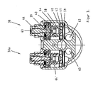
- the piston rod arrangement is mounted with first and second bushings 35 and 36, with the first bushing being arranged in association with the damper head 30 and the second bushing 36 being arranged in the end wall 37 of the damper. Adjusting devices for setting the damper characteristics in the damper are indicated by 38 and 38a (see Figure 3).
- the various components in the dampers are sealed with sealing devices in a known way. Only two seals 35a and 36a seals the piston rod.
- the damper can comprise two adjusting devices, which, in general, are designated 38 and 38a.
- the adjusting devices can be constructed in an identical way and have the same way of working.
- Each adjusting device comprises a bleed valve 39, a mushroom valve 58, a shim valve 40 and a non-return valve 41 with wave springs 59 that create a tension force (that is preferably close to zero).
- the compression bleed valve is arranged parallel to the compression mushroom valve and the expansion bleed valve is arranged parallel to the expansion mushroom valve.
- the position of the bleed valves can be changed from outside using a tool, for example a screwdriver, via an interacting means, that can, for example, consist of a screwdriver slot 60.
- the mushroom valves are urged towards their respective seatings 42 by means of preloaded springs 43.
- the preloading of the springs can be adjusted from the outside by means of an adjusting screw 44 that can be operated using a suitable tool, for example a box spanner or Allen key.
- the size of the preloading affects the opening pressure and hence the pressure differential across the main piston.
- the shim valves 40 are arranged in front of the mushroom valves.
- the shapes of the mushrooms and of the shim pack or shim stack affect the damping characteristics.
- the shim configuration can be varied.
- the construction of the damper with placing of valves, non-return valves, gas containers, ducts, etc, enables the compression and expansion valves to work independently of each other.
- a rigid shim stack can be utilized in combination with a small preloading of the mushroom valve.
- the amount of oil or fluid that is fed through the bleed valves and the shim stack can be very limited before the mushroom valve opens.
- the opening pressure of the mushroom valve depends upon the design of the mushroom valve and the valve seating and upon the preloading of the spring. By changing these parameters, among others, the character of the damping curve can be changed or selected.
- the reference numeral 62 indicates a duct that leads to the space 4
- the reference numeral 63 indicates a duct that leads to the volume 9.
- the ducts to the volume 22a start from the volumes 64, 64', which, however, are not shown in Figure 2.
- the said inner tube can be arranged to ensure the maximal rigidity in the damper construction.
- the damper utilizes bushings that are statically arranged in order to a long minimal distance between the bushings, (in this case a constant distance), compare the case where the bushings are placed on the piston, in order to minimize the friction and to achieve maximal rigidity in the damper in the event of the introduction of a bending moment and lateral loads.
- the piston is arranged without bushings.
- a piston seal that complies with non-concentricity is utilized. Two identical seals of, for example, the x-ring type can be used, one of which is used for the part of the piston rod that extends outwards externally and the other for the displacement piston rod.
- the gas container can be arranged with the same diameter as the valves, whereby the oil volume 22a between the gas-separating piston and the cylinder head can be used to transfer the oil between the two valves.
- the damper is arranged with the said pressure indicators 33, 33' in accordance with Figures 4, 5 and 6.
- the indicators work with a number of functions. Among other things, the indicators indicate whether the damper is pressurized or not. In a damper of this kind, there is no force from the internal pressurization on the piston rod that leads out of the damper body. Therefore it is difficult to determine whether the damper is pressurized or not.
- By operating one or both pressure indicators a response to any pressurizing can easily be obtained. When an indicator is depressed, the respective indicator will be expelled by any internal pressure. If there is no pressure, the indicator or indicators will remain in their depressed position.
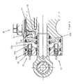
- Figure 4 shows the pressure indicators in partially depressed positions.
- the holes or the openings through which the pressure indicators can be viewed are used to tighten or loosen the top eye.
- the indicators can also be used to position the movable piston when the damper is filled with oil or emptied.
- the instrument in question is used on the top eye in order to position the piston in question.
- depressing and expelling forces are indicated by F3, F4, F5 and F6.
- the separating piston is indicated by 45 and the gas volume in the gas container is indicated by 22b'.
- the volume of fluid in the container is indicated by 22a'.
- Each indicator 33, 33' is the shape of a pin, the inner end 33a of which can be acted upon by the pressure in the volume 22b'.
- the pressure indicator pin can also be depressed to make contact with the piston 45, whereby it is possible to obtain information in a simple way about the position of the separating piston, for example a setting position. Irrespective of the setting of the adjusting devices 38 and 38a, the pressure in the volume 22a' can be maintained essentially constant.
- the reference numeral 46 shows a duct suitable for filling with oil that is sealed by a screw 47 in combination with an O-ring 61. The screw bottoms against a seat 48.
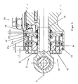
- Figure 5 is intended to show the case when the pin 33a makes contact with the upper surface 45a of the piston 45.
- the depression distances L1 and L2 can easily be established for the pressure indicator parts 33a and a space L3 can be determined indicating the position of the piston 45 in relation to an inner surface 48 in the damper head 49 that faces its underside 45b.
- a space L3 can be determined indicating the position of the piston 45 in relation to an inner surface 48 in the damper head 49 that faces its underside 45b.
- the top eye can be locked in any rotational direction along the longitudinal axis 53 by the end wall 63 of the container being screwed outward towards the locking 65 via the thread 64 and fixing the top eye in the required rotational position.
- the tool 55 or the like can be utilized for this fixing function.
- the top eye is rotated around the said longitudinal axis.
- the setting of the angle of rotation can be carried out without a risk of leakage arising from the damper.
- the top eye is given an angular position in which it is optimized for connection to the relevant moving part in or on the vehicle. By means of this setting of the angle of rotation, it is possible to adjust in which direction the adjusting device points. This is to make the adjustment on the vehicle easier.
- the said geometrical stop constitutes a locking ring 65 and a locking shoulder 66.
- the said pressure indicators can also be arranged in such a way that it is possible to check whether the damper medium and gas medium are within predetermined pressure ranges.
- the piston rod or piston rod elements are arranged to pass through and are sealed against two end walls or one end wall and one side wall.
- the piston rod or piston rod elements are arranged with essentially equal cross-sectional areas on both sides of the main piston.
- Figure 6 shows the application of a tool 50 that can interact with the tool 55 and the shoulders 51 on the top eye 52.
- the separating piston 45 is prevented from being displaced to the left in Figure 6 when the damper is filled with oil or the like under pressure.
- the filling with oil can be carried out via a duct 46, see Figure 4.
- Figure 4 also shows how force is required to press in the pressure indicators against the force from an internal overpressure of or in the gas container. This thus provides an indication of whether the damper is pressurized and makes it possible to estimate the internal overpressure.
- Figure 5 shows how the oil level in the damper can be checked by means of a tool. If the distance L3 is to be checked, this is carried out by measuring the distance L2 or, in the case illustrated, more preferably the distance L1. In the latter case, the distance L1 in an embodiment must be within the range 1+0.5/-1. This means that the distance is easy to check and to determine. If the measuring tool lies in contact with the end wall of the container, the container should be filled with oil.
- Figure 6 shows how positioning of the separating piston can be carried out, for example when filling the damper with oil under pressure.
- the cylindrical part of the top eye 15' extends essentially into an opening arranged in the damper head.
- the cylindrical part has a length that is essentially half the length of the total length of the top eye.
- the opening 15c extends along most parts of the cylindrical part which, at the part of the top eye that projects outside the damper head, has a part that is widened in the plane of the figure, which part carries the said stop surfaces for the tool 50 that can be applied.
- the stop surfaces 51 extend radially outside the cylindrical part 15b.
- the centre parts of the cylindrical part are opposite the volume 22.
- the said seals for the cylindrical part are arranged on both sides of the volume 22.
- the said stop surfaces 51 ( Figure 6) on the part 15a are essentially disc-shaped and have a thickness that is essentially the same size as the outer diameter of the tube-shaped part in the direction perpendicular to the plane of the figure in, for example, Figure 6.
- the rotating part is symmetrically arranged around a central axis.
- the part 52 is provided with an opening 52c that extends perpendicular to the plane of the figure, with a spherically-shaped unit 52a and a device 52c with a cylindrical outside and a spherical inside arranged in the opening.
- a fixing device (not shown), for example a fixing screw, can extend through an opening in the said unit 52a and can be attached in the moving part on both sides of the part 52.
- the latter part is essentially in the form of a semicircle in the plane of the figure.
- the directions of rotation of the top eye around its longitudinal axis are shown by arrows 57.
- the end eye 15 has a corresponding construction, with a cylindrical part 15d and plate-shaped part 15e.
- the piston rod 8a extends into an opening 15f in which a locking nut 151 is arranged.
- An opening 15h, extending perpendicular to the plane of the figure in Figure 2, a sphere 15i and an associated outer ring 15k are arranged to receive an elongated fixing device (not shown) that extends essentially perpendicular to the plane of the figure.
- the end eye can also assume different rotational positions around the longitudinal axis of the damper and the dimensions and design of the end eye can be selected to be similar to the top eye.
- the position of the gas-separating piston can be determined in a simple way by means of one or more of the pressure indicators described above.
- the gas-separating piston By means of a volume 22a for the medium in the accumulator or container with the gas-separating piston being comprised in a pipe run for movement of the medium between the upper and lower sides 7a, 7b of the piston, that is the main piston 7, cf. the above, no additional duct or ducts need to be arranged to set up the transference of the medium.
- Figure 7 shows the damper 1 in an end view from the top eye side, with two rotational angle positions being indicated by solid and broken lines 15' and 15".
- the top eye has been rotated through an angle ⁇ that is approximately 40°.
- the positions of the pressure indicators 33, 33' have been shown in the figure in relation to the top eye and the adjusting devices 38, 38a. Otherwise, refer to the figures described above.
- Figure 8 shows the damper in perspective, viewed obliquely from in front.
- the reference numeral 63 indicates a container end wall with the pressure indicators 33, 33' and with the top eye 15' extending from the end wall.
- the positions of the adjusting devices are shown, and the setting device (for example a screw) 60 arranged in the adjusting device 38 is shown.
- the position of the extent of the container or the accumulator 22 is also shown.
- the main spring platform and spring support have been shown by 68 and 69.
- the figure also shows the design and extent of the tube 2, and also the end eye 15 and the setting screw 47.
- Figures 9 and 10 show the damper in perspective and in exploded view.
- Figure 9 shows the movement of the medium in association with the damper's compression movement
- Figure 10 shows the movement of the medium in association with the damper's expansion movement.
- the damper's main spring is indicated by 70.
- Figure 9 shows that the flow of oil 71 is taken to the right in the figure via the arrangement described above with nose seats and valve seats. Thus the bleed and high-speed flows 72 and 73 are achieved.
- a subsidiary return flow is indicated by 74 and the main return flow is indicated by 75.
- the flows 72 and 73 are related to the valve 18 and the flow 74 is related to the valve 19, according to what is described above.
- Figure 10 operates in a corresponding way with reversed directions of flow and the relevant alternative valves activated.
- Figure 11 shows in perspective the setting parts 50 and 55 and a tool, used or able to be used with the damper, designed for rotating the end wall of the container, cf. 63 in Figure 8.
- the pins concerned protrude a short distance for fixing.
- the invention is not limited to the embodiments shown above as examples.
- the indicator(-s) 33, 33' according to claims 14-16 may work in other applications for vehicles than described combined with members 2, 3, 7, 8, 22, only.
- the same is valid for the sealing arrangement including seals 35a, 36a, according to claims 23 and 29, which attains a low or small friction.
- This separate invention is combined with the same above mentioned members.
- the complete sealing arrangement includes the seals of the members 15" and 22, as well.
- the piston rod of figure 1 A is not through going the cylinder space 9, 10 and is sealed by only one seal, compare seal 36a in figure 1.
- the damper end 8d do not have space for journaling any rod or rod part as in figure 1. Otherwise, the structure of figure 1A corresponds that of figure 1.
Landscapes
- Engineering & Computer Science (AREA)
- General Engineering & Computer Science (AREA)
- Mechanical Engineering (AREA)
- Fluid-Damping Devices (AREA)
Abstract
Description
- The present invention relates to a damper (shock absorber) intended for vehicles which is arranged with selectable or adjustable damping force characteristics that are essentially independent of other internal or external function factors in the damper. It relates primarily to vehicles in the form of cars, motorcycles, snow-scooters, etc, where the damper is arranged between movable parts comprised in the vehicle, for example between wheels, runners, etc, and a chassis.
- Dampers of this kind are found in large numbers and reference can be made, for example, to shock absorbers that are sold by the applicant making the present patent application. Reference is also made to patents that have been obtained by the applicant and to patent applications previously submitted by the applicant within this field.
- With this kind of damper, there is a desire for the damper's functional and/or handling characteristics to be able to be improved and made more clear-cut and yet still be able to have a simplified and less bulky construction. The object of the invention is, among other things, to solve all or parts of this problem.
- There is also a need for the damper's damping force characteristics to be able to be made more clear-cut and for set or selected damping characteristics to be able to be selected when assembling dampers and when making adjustments, without at the same time affecting any other function or functions in the damper. Thus, for example, in an embodiment, the damping force characteristics must be able to be set without, for example cavitation arising or being increased or reduced. The damper's fixing must also be able to be made more clear-cut and compact constructions must be able to be arranged. Hysteresis and so-called "flex" must be able to be essentially minimized. Where a compressible medium is utilized to pressurize the damper, it is important that the gas volumes are kept to a minimal level. The pressurizing by means of the compressible medium or corresponding function (for example a spring function) is in order to increase the viscosity of the oil or fluid and to reduce the risk of cavitation. In addition to the ability to reduce the size of the damper as such while retaining good functionality, there is a desire to achieve effective cooling of the medium or mediums used in the damper. It is also important to ensure good and economically advantageous sealing and/or guiding functions that produce relatively small frictional forces on the piston rod or on the piston rod elements during their movements in the damper. Thus, for example, there is a desire to minimize the friction on the piston rod or the piston rod elements by using the least possible number of seals and/or bushings for guiding the piston rod in the cylinder barrel and through the end walls of the cylinder barrel or the like. Thus, for example, it must be possible to use a floating seal and to reduce the dimension tolerances of the cylinder barrel. The volume of the damper medium or mediums must be able to be kept within a certain range, in order to ensure the function of the damper. In a preferred embodiment, in a damper utilizing a separating piston, it must be possible to read off or determine the position of the separating piston. This must be able to be carried out without, for example, having to dismantle all or parts of the damper. An end eye utilized as a fixing device must, in addition, be able to be arranged in such a way that no resulting force will arise on the piston rod as a result of the internal overpressure that is caused by the compression of the medium concerned. There can also be difficulties in determining whether the damper is pressurized or not. There are also problems in being able to ensure that a separating piston that is utilized is in the correct position when the damper is filled with the medium. A relatively large amount of work has previously been required in order to ensure this and there is a desire to be able to reduce this work. It is also important to be able to prevent the damper medium leaking out as a result of a separating piston that is utilized leaving its sealed course during the filling. When a pressure indicator is utilized to check the quantity of damper medium, there is a need for simple pressure indication functions that are easy to use but that are still clear-cut in their function. Among other things, it is important that the connection hole or holes for the pressure indictors can be made relatively small. There is also a desire for the seal(s)/bushing(s) to be located as close to the main piston as possible, in order to minimize the length of the piston rod arrangement and thereby minimize the total length of the damper, without increasing the cost of production. Where a top eye is utilized, it must be able to be mounted at any angle to the body of the damper in a simple way, without the locking of the top eye encroaching upon the length of the damper. The object of the invention is also to solve all or parts of these additional problems.
- The principal characteristics of a damper according to the invention are based on a unique combination of elements that can be combined, which elements may perhaps be completely or partially previously known individually. Thus, for example, the invention is characterized in that it comprises an operating device or devices with valves and pipes with a surrounding arrangement, piston arrangement and piston rod arrangement, provided with fixing devices that make possible connection to parts of the vehicle that move relative to each other. In the event of a damping force arising on the arrangement's piston in a certain direction of the piston, this device or these devices are arranged to ensure that there is an increase in pressure on the side of the piston facing towards the direction, while the pressure is essentially maintained on the side of the piston facing away from the direction. This function is called a positive pressure build-up function, in association with the present invention. The invention is also characterized in that the said operating device or devices are arranged to bring about the independent damping force characteristics mentioned in the introduction. In addition, pressure-maintaining devices are arranged to ensure that the pressure in the arrangement is maintained in the event of the occurrence of pressure-affecting parameters that try to change the pressure. Examples of such parameters are changes in temperature, changes in volume, changes in the piston rod displacement, etc. Finally, the damper is preferably arranged with adjusting devices that determine the damping force characteristics according to their setting. Detecting devices are preferably also utilized, for example in the form of the said pressure indictors.
- In a preferred embodiment, the damper is provided with a piston rod arrangement that goes through the piston (the main piston) or extends from both sides of the piston with one or more piston rod elements extending from each side. By this means, the piston rod displacement on one side of the piston can be counteracted by the change or changes in volume caused by the piston rod displacement(s) on the other side of the piston. In an additional embodiment, the operating device with valves and pipes comprises a volume connected to the internal volume or barrel of the surrounding arrangement or of the cylinder arrangement via valves, for example non-return valves, which volume forms a low-pressure zone which is, in turn, connected to the pressure-maintaining device that thereby can comprise a pressure-generated piston arranged to be able to be operated by the effect of a resistance device or a compressible gas that is arranged in an accumulator or gas container. Alternatively or in addition, the resistance device can consist of a spring arrangement or a device working in a corresponding way. By means of the connection via the said valves, that, for example, can comprise one or more non-return valves, the volume or low-pressure zone in question ensures the positive pressure build-up in association with the movements of the piston in the said barrel. In the said preferred embodiments, the damper can consist of what is called a twin-tube damper, that is a damper with double tubes and, with such a damper, the damper medium concerned is arranged to be able to be fed in the space between the inner and outer tube of the twin-tube damper from one side of the piston to the other side via the said valves. The pressure-maintaining device preferably comprises a gas-separating piston. A first fixing device can comprise, for example, an end eye. The end eye is attached to or constitutes part of the piston rod arrangement. A second fixing device can comprise a fixing eye or top eye. Alternatively or in addition, the damper can be attached to one of the vehicle's movable parts via another part of the damper's body or outer part. The damper can be constructed as a common unit where the surrounding arrangement or the cylinder arrangement is connected to a damper head and extends from this to the first end of the unit. The pressure-maintaining device can be arranged in association with the damper head or with the other side of the damper head. The indicators and adjusting devices for volumes and damping characteristics can be arranged in association with the said damper head that can consist of a part of the damper. The guiding of the piston or piston rod element can be carried out by means of bushings placed on each side of the cylinder barrel in such a way that, for example, a first bushing is arranged at an end wall or support element placed outside the cylinder barrel and a bushing is mounted in the said damper head or in a component or components mounted on this. The piston rod or piston rod elements are arranged in association with the cylinder barrel and pass through the end walls. The low pressure zone is arranged in association with the damper head and is arranged as a component with a central hole or in a component with a central hole, through which the piston rod part or the piston rod elements concerned operate. Sealing can be carried out by means of seals that form a seal against the top eye that has a tube-shaped part, through the hole in which the piston rod or the piston rod elements concerned can pass. By utilizing the volume in association with the separating piston for transference of the damper medium between both sides of a piston (main piston), the parts that delimit the gas container contribute to efficient cooling, as large quantities of damper medium can pass through.
- Additional further developments of the concept of the invention are apparent from the following subsidiary claims.
- A currently preferred embodiment of a damper that has the significant characteristics of the invention will be described below with reference to the attached drawings in which:
- Figures 1 and 1 A shows different dampers and components connected to this or comprised in this, in outline,
- Figure 2 shows parts of a constructive embodiment of the damper, in longitudinal section,
- Figure 3 shows the damper according to Figure 2, in cross-section and enlarged in relation to Figure 2,
- Figures 4-6 show the damper's components for the damper head, in longitudinal section and enlarged, and
- Figures 7-11 show the detailed construction of the damper in a perspective view, an end view and an exploded diagram.
- In Figure 1, parts of a damper are indicated in outline by 1. In the embodiment, the damper consists of a twin-tube damper, with an outer tube indicated by 2 and an inner tube indicated by 3. The tubes are arranged with a
space 4 in between and have, at the first end of the damper,passages main piston 7 and apiston rod 8 extending through themain piston 7, with the piston rod parts on one side of the piston being indicated by 8a and the piston rod part on the other side of the piston being indicated by 8b. The damper's compression volume or compression side is indicated by 9 and the expansion volume or expansion side is indicated by 10. The piston and the piston rod are arranged in thecylinder barrel arrows 11. Thepiston 7 operates in a medium 13 that preferably consists of hydraulic oil that can comprise associated additives in a known way. Alternatively, glycol and/or water can be utilized as the fluid. Thepiston rod 8a and 8b can extend from the upper andlower sides 7a and 7b of the piston respectively. The piston rod can, in principal, comprise piston rod element parts that can be more than one in number. Thus, the piston rod part 8a and/or 8b can consist of more than one piston rod part or piston rod element. Thus, for example, the piston rod part 8a can consist of one piston rod part, while thepiston rod part 8b can be replaced by two or more piston rod elements. The end wall parts of the damper are indicated by 12 and 12'. Thepiston rod end 8c on the piston rod part 8a has a fixing device 15 (for example, an end eye) to a part of a vehicle concerned, which part can consist of a wheel suspension component (hub, shaft, etc) 14. On thedamper end 8d, the damper has a fixing device 15' (for example, a top eye) that can be attached to apart 16 of the chassis of a vehicle concerned. The damper is arranged with a valve arrangement that is indicated in outline by 17. In the present application, the valve arrangement is called an operating device. The said device comprises a first damping force generating valve orcompression damping valve 18 and a firstnon-return valve 19. In addition, there is a second damping force generating valve or return dampingvalve 20 and a secondnon-return valve 21. These damping force generating valves can consist of one or more valves connected in parallel and/or in series. In accordance with Figure 1, there is also an accumulator orgas container 22 that comprises aseparating piston 23. In afirst volume 22a, the gas container holds a medium 13, for example the said hydraulic oil with any additives or other fluid (see above). The gas container also has asecond volume 22b that holds a second medium 24 that is more compressible than the medium 13. The medium 24 can consist of gas, for example air, nitrogen or other gas with additives. The saidoperating device 17 also comprises pipes that interconnect the saidvalves volume 22a in thecontainer 22 and that interconnect the saidspace 4 and thevolumes space 4 and thevolume 10 can be regarded as a common volume. The saidvalves volume 19, the pipe 27', thevolume 22a and thepipe 27, and in which thespace 4 and the passage(s) 5 and 6 are also connected, and similarly thevolume 10. A second loop consists of thevalves arrows 26, while the direction of flow in association with expansion of the shock absorber, often called the return phase, is indicated by the arrows 26'. It is also fully possible, in an embodiment, to incorporate valves in themain piston 7 that are used in combination with other valves. The first dampingforce generating valve 18 is connected at one end to thevolume 9 in the damper, while the firstnon-return valve 19 is connected to thespace 4. The second dampingforce generating valve 20 is connected to thespace 4, while the second non-return valve is connected to thevolume 9. The saidfirst valves second valves pipes piston 7 moves to the left in Figure 1, the medium 13 is forced via thevalve 18 and the intermediate pipe andnon-return valve 19 into thespace 4. Thespace 4 thus carries the medium, that was fed from thevolume 9, to thevolume 10. Depending upon the design of thevalve 20, more or less medium can also be fed from thevolume 9, via thevalve 18, the pipe 27', thevolume 22a, thepipe 27 and backwards through the valve 20 (that is against the indicated direction of the arrow 26') and thespace 4 to thevolume 10, cf. so-called bleed function. In a corresponding way, in association with an expansion movement, that is movement of the piston to the right in Figure 1, the medium is fed from thevolume 10 to thevolume 9 via intermediate pipes, thespace 4, thevalve 20, thevolume 22a and thevalve 21. Also here, it is the case that more or less medium can be fed to thevolume 9, via thepipes 27, 27' and backwards through the valve 18 (against the indicated direction of the arrow 26), cf. bleed function. In the present application, this transferring function between thevolumes volume 10 will thus essentially maintain its pressure value in spite of the movement. In a corresponding way, the medium in thevolume 9 maintains its pressure value when the piston moves to the right, due to the said transferring of medium. If, for example, the piston moves in the direction of thearrow 11 a, then the pressure increase on theside 7a of the piston that is facing in that direction will be increased by thevalve function 18 while, at the same time, cavitation effects are avoided on the side 7b facing away from the direction ofmovement 11a. Corresponding increases apply for movements in the direction of thearrow 11b. The direction of movement of the medium in thespace 4 and thepassages
Figure 1 also shows alow pressure zone 29 for the enclosed medium, which can consist of, for example, hydraulic oil, nitrogen, etc. The said gas container with gas-separatingpiston 23 ensures that there is a suitable pressure, that is a suitable medium pressure, in thedamper 1 in the event of changes in volume. Thus, suitable pressure levels are ensured in the event of changes in the sealed volume due to, for example, changes in temperature in the medium volume, changes in the piston rod displacement, etc. The pressurizing means that the absolute pressure level is maintained at a suitable level, for example at a level of approximately 2 bar or higher, in order to minimize the risk of cavitation due to restrictions that are in the ducts concerned. The maintaining of the gas pressure in the medium volume that is facing away from the direction of movement is, to a certain extent, determined by the drop in pressure that is caused by the valves and the pipes or ducts. The medium pressure at the side facing away from the direction of movement must, however, be essentially maintained on a level with the value that applies for a stationary piston. Figure 1 shows forces transferred to the piston rod indicated by F1 and F2. Thevalves space 4 and thevolume 10. Thereference numeral 25 is intended to symbolize the pipe system or said operating device in its entirety. - Figure 2 shows a constructive embodiment of the
damper 1 that has a form that is called a twin-tube damper. The damper comprises a damper head 30 (here named a part). The inner and outer tube forming the twin-tube damper are arranged on one side of the damper head. Thegas pressure container 22 mentioned above is arranged on or in the damper head, on its other side. Thecontainer 22 has the form of a ring-shaped component that is sealed against the fixing device 15' by means ofseals 32 and 32' and against the damper head by means ofseals 32" and 32"'. In addition, there is aseal 31 that prevents leakage of the damper medium into the inside of the fixing device. The said fixing device has a fixing part 15a and acylindrical part 15b, on the outside of which the said seals 31, 32 and 32' are arranged. The saidpiston rod part 8b is arranged to be able to move inside theopening 15c in the cylindrical part when the piston moves. Pressure-indicating devices are shown by 33 and 33'. The position of the floating piston 23 (see Figure 1) can be determined by means of these indicating devices. In this case, the piston is mounted on acommon piston rod 8a, 8b that can comprise parts that can be assembled. The piston rod arrangement is mounted with first andsecond bushings damper head 30 and thesecond bushing 36 being arranged in theend wall 37 of the damper. Adjusting devices for setting the damper characteristics in the damper are indicated by 38 and 38a (see Figure 3). In general, the various components in the dampers are sealed with sealing devices in a known way. Only twoseals - In accordance with Figure 3, the damper can comprise two adjusting devices, which, in general, are designated 38 and 38a. The adjusting devices can be constructed in an identical way and have the same way of working. Each adjusting device comprises a
bleed valve 39, amushroom valve 58, ashim valve 40 and anon-return valve 41 with wave springs 59 that create a tension force (that is preferably close to zero). The compression bleed valve is arranged parallel to the compression mushroom valve and the expansion bleed valve is arranged parallel to the expansion mushroom valve. The position of the bleed valves can be changed from outside using a tool, for example a screwdriver, via an interacting means, that can, for example, consist of ascrewdriver slot 60. The mushroom valves are urged towards theirrespective seatings 42 by means of preloaded springs 43. The preloading of the springs can be adjusted from the outside by means of an adjustingscrew 44 that can be operated using a suitable tool, for example a box spanner or Allen key. The size of the preloading affects the opening pressure and hence the pressure differential across the main piston. Theshim valves 40 are arranged in front of the mushroom valves. The shapes of the mushrooms and of the shim pack or shim stack affect the damping characteristics. The shim configuration can be varied. The construction of the damper with placing of valves, non-return valves, gas containers, ducts, etc, enables the compression and expansion valves to work independently of each other. In one embodiment, a rigid shim stack can be utilized in combination with a small preloading of the mushroom valve. The amount of oil or fluid that is fed through the bleed valves and the shim stack can be very limited before the mushroom valve opens. The opening pressure of the mushroom valve depends upon the design of the mushroom valve and the valve seating and upon the preloading of the spring. By changing these parameters, among others, the character of the damping curve can be changed or selected. Thereference numeral 62 indicates a duct that leads to thespace 4, while thereference numeral 63 indicates a duct that leads to thevolume 9. The ducts to thevolume 22a start from thevolumes 64, 64', which, however, are not shown in Figure 2. The said inner tube can be arranged to ensure the maximal rigidity in the damper construction. The damper utilizes bushings that are statically arranged in order to a long minimal distance between the bushings, (in this case a constant distance), compare the case where the bushings are placed on the piston, in order to minimize the friction and to achieve maximal rigidity in the damper in the event of the introduction of a bending moment and lateral loads. In a preferred embodiment, the piston is arranged without bushings. As an alternative in such a case, a piston seal that complies with non-concentricity is utilized. Two identical seals of, for example, the x-ring type can be used, one of which is used for the part of the piston rod that extends outwards externally and the other for the displacement piston rod. Due to the low gas pressure, the friction from the seals can be kept to a low level. The gas container can be arranged with the same diameter as the valves, whereby theoil volume 22a between the gas-separating piston and the cylinder head can be used to transfer the oil between the two valves. - The damper is arranged with the said
pressure indicators 33, 33' in accordance with Figures 4, 5 and 6. The indicators work with a number of functions. Among other things, the indicators indicate whether the damper is pressurized or not. In a damper of this kind, there is no force from the internal pressurization on the piston rod that leads out of the damper body. Therefore it is difficult to determine whether the damper is pressurized or not. By operating one or both pressure indicators, a response to any pressurizing can easily be obtained. When an indicator is depressed, the respective indicator will be expelled by any internal pressure. If there is no pressure, the indicator or indicators will remain in their depressed position. Figure 4 shows the pressure indicators in partially depressed positions. The holes or the openings through which the pressure indicators can be viewed are used to tighten or loosen the top eye. The indicators can also be used to position the movable piston when the damper is filled with oil or emptied. The instrument in question is used on the top eye in order to position the piston in question. In Figure 4, depressing and expelling forces are indicated by F3, F4, F5 and F6. In this case, the separating piston is indicated by 45 and the gas volume in the gas container is indicated by 22b'. The volume of fluid in the container is indicated by 22a'. Eachindicator 33, 33' is the shape of a pin, theinner end 33a of which can be acted upon by the pressure in thevolume 22b'. Theshoulder 33b on the pressure indicator bottoms against theshoulder 62 in the end wall of the container if there is an internal overpressure and no external force applied by means of a tool (see for example Figure 5) or the like. The pressure indicator pin can also be depressed to make contact with thepiston 45, whereby it is possible to obtain information in a simple way about the position of the separating piston, for example a setting position. Irrespective of the setting of the adjustingdevices volume 22a' can be maintained essentially constant. Thereference numeral 46 shows a duct suitable for filling with oil that is sealed by ascrew 47 in combination with an O-ring 61. The screw bottoms against aseat 48. - Figure 5 is intended to show the case when the
pin 33a makes contact with theupper surface 45a of thepiston 45. By depressing therespective pressure indicator 33, 33' using thetool 55, the depression distances L1 and L2 can easily be established for thepressure indicator parts 33a and a space L3 can be determined indicating the position of thepiston 45 in relation to aninner surface 48 in thedamper head 49 that faces itsunderside 45b. By this means, it can easily be checked that the position of theseparating piston 45 and thereby the level of the damping medium are within a predetermined approved operating area. By the utilization of two pressure indicators, it is ensured that acting upon the piston by means of the pressure indicators can be carried out without significant uneven loading of the piston. The top eye can be locked in any rotational direction along thelongitudinal axis 53 by theend wall 63 of the container being screwed outward towards the locking 65 via thethread 64 and fixing the top eye in the required rotational position. Thetool 55 or the like can be utilized for this fixing function. In the said setting of the angle of rotation, the top eye is rotated around the said longitudinal axis. The setting of the angle of rotation can be carried out without a risk of leakage arising from the damper. At the same time, the top eye is given an angular position in which it is optimized for connection to the relevant moving part in or on the vehicle. By means of this setting of the angle of rotation, it is possible to adjust in which direction the adjusting device points. This is to make the adjustment on the vehicle easier. When the top eye has been set in the rotational angle, it is locked to the body of the damper head with ascrew connection 64. The said geometrical stop constitutes a lockingring 65 and a lockingshoulder 66. The said pressure indicators can also be arranged in such a way that it is possible to check whether the damper medium and gas medium are within predetermined pressure ranges. - The piston rod or piston rod elements are arranged to pass through and are sealed against two end walls or one end wall and one side wall. The piston rod or piston rod elements are arranged with essentially equal cross-sectional areas on both sides of the main piston.
- Figure 6 shows the application of a
tool 50 that can interact with thetool 55 and theshoulders 51 on thetop eye 52. By mounting these tools, theseparating piston 45 is prevented from being displaced to the left in Figure 6 when the damper is filled with oil or the like under pressure. The filling with oil can be carried out via aduct 46, see Figure 4. - Figure 4 also shows how force is required to press in the pressure indicators against the force from an internal overpressure of or in the gas container. This thus provides an indication of whether the damper is pressurized and makes it possible to estimate the internal overpressure. Figure 5 shows how the oil level in the damper can be checked by means of a tool. If the distance L3 is to be checked, this is carried out by measuring the distance L2 or, in the case illustrated, more preferably the distance L1. In the latter case, the distance L1 in an embodiment must be within the
range 1+0.5/-1. This means that the distance is easy to check and to determine. If the measuring tool lies in contact with the end wall of the container, the container should be filled with oil. Figure 6 shows how positioning of the separating piston can be carried out, for example when filling the damper with oil under pressure. - The cylindrical part of the top eye 15' extends essentially into an opening arranged in the damper head. In this embodiment, the cylindrical part has a length that is essentially half the length of the total length of the top eye. The
opening 15c extends along most parts of the cylindrical part which, at the part of the top eye that projects outside the damper head, has a part that is widened in the plane of the figure, which part carries the said stop surfaces for thetool 50 that can be applied. The stop surfaces 51 extend radially outside thecylindrical part 15b. The centre parts of the cylindrical part are opposite thevolume 22. The said seals for the cylindrical part are arranged on both sides of thevolume 22. The said stop surfaces 51 (Figure 6) on the part 15a are essentially disc-shaped and have a thickness that is essentially the same size as the outer diameter of the tube-shaped part in the direction perpendicular to the plane of the figure in, for example, Figure 6. The rotating part is symmetrically arranged around a central axis. Thepart 52 is provided with an opening 52c that extends perpendicular to the plane of the figure, with a spherically-shapedunit 52a and a device 52c with a cylindrical outside and a spherical inside arranged in the opening. A fixing device (not shown), for example a fixing screw, can extend through an opening in the saidunit 52a and can be attached in the moving part on both sides of thepart 52. The latter part is essentially in the form of a semicircle in the plane of the figure. The directions of rotation of the top eye around its longitudinal axis are shown byarrows 57. Theend eye 15 has a corresponding construction, with acylindrical part 15d and plate-shapedpart 15e. The piston rod 8a extends into an opening 15f in which alocking nut 151 is arranged. Anopening 15h, extending perpendicular to the plane of the figure in Figure 2, a sphere 15i and an associatedouter ring 15k are arranged to receive an elongated fixing device (not shown) that extends essentially perpendicular to the plane of the figure. The end eye can also assume different rotational positions around the longitudinal axis of the damper and the dimensions and design of the end eye can be selected to be similar to the top eye. By means of what is proposed, the position of the gas-separating piston can be determined in a simple way by means of one or more of the pressure indicators described above. By means of avolume 22a for the medium in the accumulator or container with the gas-separating piston being comprised in a pipe run for movement of the medium between the upper andlower sides 7a, 7b of the piston, that is themain piston 7, cf. the above, no additional duct or ducts need to be arranged to set up the transference of the medium. This means, in turn, that it is possible to reduce the volume of the damper as such and/or means that it is possible to reduce the manufacturing costs. As the piston rod arrangement is sealed in the damper arrangement by means of only two seals or sealing elements, the arrangement can operate with an optimally small friction. To date, at least three seals have been required. - Figure 7 shows the
damper 1 in an end view from the top eye side, with two rotational angle positions being indicated by solid andbroken lines 15' and 15". In this case, the top eye has been rotated through an angle α that is approximately 40°. In addition, the positions of thepressure indicators 33, 33' have been shown in the figure in relation to the top eye and the adjustingdevices - Figure 8 shows the damper in perspective, viewed obliquely from in front. The
reference numeral 63 indicates a container end wall with thepressure indicators 33, 33' and with the top eye 15' extending from the end wall. Similarly, the positions of the adjusting devices are shown, and the setting device (for example a screw) 60 arranged in the adjustingdevice 38 is shown. The position of the extent of the container or theaccumulator 22 is also shown. The main spring platform and spring support have been shown by 68 and 69. The figure also shows the design and extent of thetube 2, and also theend eye 15 and the settingscrew 47. - Figures 9 and 10 show the damper in perspective and in exploded view.
Figure 9 shows the movement of the medium in association with the damper's compression movement and Figure 10 shows the movement of the medium in association with the damper's expansion movement. The damper's main spring is indicated by 70. Concerning the flow of oil or medium shown in the figures, reference is also made to Figures 1 and 2. Figure 9 shows that the flow ofoil 71 is taken to the right in the figure via the arrangement described above with nose seats and valve seats. Thus the bleed and high-speed flows 72 and 73 are achieved. A subsidiary return flow is indicated by 74 and the main return flow is indicated by 75. Theflows valve 18 and theflow 74 is related to thevalve 19, according to what is described above. Figure 10 operates in a corresponding way with reversed directions of flow and the relevant alternative valves activated. Figure 11 shows in perspective thesetting parts - The indicator(-s) 33, 33' according to claims 14-16 may work in other applications for vehicles than described combined with
members arrangement including seals claims members 15" and 22, as well. The piston rod of figure 1 A is not through going thecylinder space seal 36a in figure 1. Thedamper end 8d do not have space for journaling any rod or rod part as in figure 1. Otherwise, the structure of figure 1A corresponds that of figure 1.
Claims (30)
- Damper (shock absorber) intended for vehicles with selectable or adjustable damping force characteristics that are essentially independent of other internal or external function factors in the damper, characterized in that it comprises an operating device or devices with valves and pipes with a surrounding arrangement, piston arrangement and piston rod arrangement, provided with fixing devices that make possible connection to parts of the vehicle that move relative to each other, which device or devices are arranged, in the event of a damping force arising on the arrangement's piston in a certain direction of the piston, to ensure that there is an increase in pressure on the side of the piston facing towards the direction, while the pressure is essentially maintained on the side of the piston facing away from the direction, here called a positive pressure build-up, in that the said operating device or devices are arranged to bring about the independent damping force characteristics, in that pressure-maintaining devices are arranged to ensure the maintaining of the pressure in the arrangement in the event of pressure-affecting parameters that try to change the pressure, for example changes in temperature, changes in volume, changes in the piston rod displacement, etc, and in that the damper is preferably arranged with adjusting devices that determine the damping force characteristics according to their setting.
- Damper according to Claim 1, characterized in that the piston rod arrangement goes through the piston or extends from both sides of the piston with one or more piston rod elements extending from each side, and in that the piston rod displacement on one side of the piston can be counteracted by the change or changes in volume caused by the piston rod displacement on the other side of the piston.
- Damper according to Claim 1 or 2, characterized in that the operating device with valves and pipes comprises a volume or barrel connected to the internal volume of the surrounding arrangement, for example, the cylinder arrangement, which volume forms a low-pressure zone which is, in turn, connected to the pressure-maintaining device that thereby comprises a pressure-generating piston arranged to be able to be operated by a compressible gas in an accumulator or gas container, a spring arrangement or a device working in a corresponding way and in that the volume or low-pressure zone ensures the positive pressure build-up in association with the movements of the piston in the said barrel by means of the connection via the said valves, for example one or more non-return valves.
- Damper according to Claim 1, 2 or 3, characterized in that the operating device with valves and pipes comprises a first pipe that extends in a space between the inner and outer tube parts in the surrounding arrangement or the cylinder arrangement that thereby form a twin-tube arrangement, that is the damper consists of a twin-tube damper and in that the damper medium is arranged to be able to be fed in the space from one side of the piston to the other side via the said valves.
- Damper according to Claim 3 or 4, characterized in that the said pressure-maintaining device or the pressure-maintaining piston consists of a gas-separating piston that separates the damping medium in the form of a fluid from the compressible medium that comes into effect when the said parameters occur.
- Damper according to any one of the preceding claims, characterized in that the fixing device or fixing devices consist of or comprise a top eye and/or an end eye, and in that the top eye is separated from the piston rod arrangement while the end eye is attached to or constitutes a part of the piston rod arrangement.
- Damper according to any one of the preceding claims, characterized in that it forms a common unit that comprises the surrounding arrangement or the cylinder arrangement and a piston rod part projecting from this and also comprises the pressure-maintaining device and fixing devices, for example a top eye, arranged on a part forming the damper head.
- Damper according to Claim 7, characterized in that the gas-separating piston comprised in the pressure-maintaining device is sealed internally against a component placed outside the path of movement of the piston rod or piston rod elements concerned.
- Damper according to Claim 8, characterized in that a part of the top eye constitutes the component.
- Damper according to any one of the preceding claims, characterized in that the pressure-maintaining device or the gas-separating piston is arranged essentially to eliminate tendencies towards cavitation and/or hysteresis/flex in association with movements of the main piston in the barrel, and also to compensate for changes in volume caused by changes in temperature and/or changes in the piston rod displacement.
- Damper according to any one of the preceding claims, characterized in that one or more, preferably all, of the said valves are located in such a way that they are separated from the main piston or the piston rod or piston rod elements for (easy) access for carrying out replacement or adjustment.
- Damper according to any one of the preceding claims, characterized in that, for the piston rod arrangement that passes through the barrel, sealing against the inner wall of the barrel is arranged by means of a floating seal that reduces the number of bushings that guide the piston arrangement and piston rod arrangement in association with the barrel to two bushings that are located inside or outside the barrel, and in that the floating seal is arranged on the main piston or on the piston rod/piston rod element concerned, which enables tolerances to be increased concerning the shape, position and/or dimension of the barrel and the positions of the bushings.
- Damper according to any one of Claims 1-12, characterized in that it is arranged with one or more pressure indicators.
- Damper according to Claim 13, characterized in that the said pressure indicator or said pressure indicators are arranged to determine whether the damper is pressurized or not.
- Damper according to Claim 13 or 14, characterized in that the said pressure indicator or said pressure indicators are arranged to check that the damper medium and gas medium lie within predetermined pressure ranges.
- Damper according to Claim 13, 14 or 15, characterized in that the said pressure indicator or said pressure indicators are arranged to determine the position of the separating piston in the accumulator in a simple way.
- Damper according to any one of Claims 13-16, characterized in that the indication is arranged to be carried out with the accumulator's end wall in assembled position.
- Damper according to any one of Claims 13-17, characterized in that the cover of the accumulator is arranged with a geometric engagement.
- Damper according to any one of Claims 13-18, characterized in that one or more of the said pressure indicators are arranged with depression devices, by means of which the current state can be determined by means of the amount of depression that has been achieved and/or by means of a detected resistance force generated in the depression device(s).
- Damper according to any one of Claims 7-19, characterized in that the part's or partition's bushing for the piston rod arrangement is located in close association with the main piston, in order to minimize the length of the displacement piston rod or displacement piston rod elements and thereby minimize the length of the damper as such.
- Damper according to any one of the preceding claims, characterized in that the top eye is arranged to be mounted in a predetermined or adjustable rotational angle around the longitudinal axis of the damper.
- Damper according to Claim 21, characterized in that the top eye is able to be mounted in the end wall of the gas container or the end wall of the accumulator by means of a threaded connection, in that the end wall is prevented from rotating by friction arising from a geometric stop, for example in the form of the cylinder head and a locking ring.
- Damper according to any one of Claims 2-22, characterized in that the piston rod or piston rod elements are arranged to pass through and are sealed against two end walls or one end wall and one side wall.
- Damper according to any one of Claims 2-23, characterized in that the said operating device comprises a first damping force generating valve or compression damping valve, connected to the cylinder's compression volume and a first non-return valve connected to the said space, and also a second damping force generating valve or return damping valve connected to the space and a second non-return valve connected to the compression volume.
- Damper according to any one of Claims 2-24, characterized in that the space connects the compression volume and the expansion volume via one or more passages at one end of the inner and outer tubes.
- Damper according to any one of the preceding claims, characterized in that the cross-sectional areas of the piston rod or piston rod elements are essentially equal on both sides of the piston.
- Damper according to any one of Claims 13-16, characterized in that the position of the gas-separating piston can be determined by one or more of the said pressure indicators.
- Damper according to any one of Claims 5-27, characterized in that a volume (22a) for the medium in the accumulator or container of the gas-separating piston is comprised in a pipe run for movement of the medium between the upper and lower sides (7a, 7b) of the piston, (the main piston 7), whereby no additional duct or ducts need to be arranged to set up the pipe run, which in turn makes it possible to reduce the volume of the damper as such and/or makes it possible to reduce the manufacturing costs for the damper as such.
- Damper according to any one of the preceding claims, characterized in that the piston rod arrangement is sealed in the damper arrangement by means of only two seals or sealing elements, and thereby can operate with an optimally small friction.
- Damper according to any one of the preceding claims, characterized in that it comprises or can interact with an appropriate tool for setting the rotational angle position of the eye on or in the damper, and in that the top eye and/or the tool are arranged to assume different rotational positions, where the top eye is locked or can be locked in the set or required rotational angle position.
Applications Claiming Priority (1)
| Application Number | Priority Date | Filing Date | Title |
|---|---|---|---|
| SE0402820A SE0402820L (en) | 2004-11-18 | 2004-11-18 | Dampers intended for vehicles (shock absorbers) |
Publications (3)
| Publication Number | Publication Date |
|---|---|
| EP1659310A2 true EP1659310A2 (en) | 2006-05-24 |
| EP1659310A3 EP1659310A3 (en) | 2006-11-15 |
| EP1659310B1 EP1659310B1 (en) | 2009-10-21 |
Family
ID=33516480
Family Applications (1)
| Application Number | Title | Priority Date | Filing Date |
|---|---|---|---|
| EP05445066A Expired - Lifetime EP1659310B1 (en) | 2004-11-18 | 2005-08-24 | Damper (shock absorber) intended for vehicles |
Country Status (4)
| Country | Link |
|---|---|
| US (1) | US7607522B2 (en) |
| EP (1) | EP1659310B1 (en) |
| DE (1) | DE602005017237D1 (en) |
| SE (1) | SE0402820L (en) |
Cited By (6)
| Publication number | Priority date | Publication date | Assignee | Title |
|---|---|---|---|---|
| EP2112401A1 (en) | 2008-04-25 | 2009-10-28 | Trek Bicycle Corporation | Bicycle shock assemblies |
| WO2010049524A1 (en) * | 2008-10-31 | 2010-05-06 | öHLINS RACING AB | Arrangement for telescopic fork leg with parallel damping |
| EP2118515A4 (en) * | 2007-02-06 | 2011-07-20 | Oehlins Racing Ab | SHOCK ABSORBER COMPRISING HYDRAULIC PIPES |
| EP3517801A1 (en) * | 2018-01-29 | 2019-07-31 | Fox Factory, Inc. | Twin tube shock with adjustable pressure regulation |
| US12504055B2 (en) | 2017-01-30 | 2025-12-23 | Fox Factory, Inc. | Twin tube shock with adjustable pressure regulation |
| US12510129B2 (en) | 2017-01-30 | 2025-12-30 | Fox Factory, Inc. | Twin tube shock with adjustable pressure regulation |
Families Citing this family (35)
| Publication number | Priority date | Publication date | Assignee | Title |
|---|---|---|---|---|
| US20060090973A1 (en) * | 2004-10-28 | 2006-05-04 | Michael Potas | Valve system controlled by rate of pressure change |
| US7631922B2 (en) * | 2006-08-25 | 2009-12-15 | Stabilus, Inc. | Tailgate dampening apparatus |
| US9494209B1 (en) | 2007-06-21 | 2016-11-15 | Bill J. Gartner | Regressive hydraulic damper |
| GB2458456B (en) * | 2008-03-15 | 2010-08-25 | Tech Suspension Ltd K | Adjustable piston damper to fit in an OEM telescopic suspension fork |
| US8733519B2 (en) * | 2009-01-23 | 2014-05-27 | Jri Development Group, Llc | Linear impelled module damper |
| US8807300B2 (en) | 2009-10-26 | 2014-08-19 | Fox Factory, Inc. | Methods and apparatus for managing pressurized gas in fluid dampers |
| US10953716B2 (en) | 2009-10-26 | 2021-03-23 | Fox Factory, Inc. | Methods and apparatus for managing pressurized gas in fluid dampers |
| WO2011068520A1 (en) * | 2009-12-04 | 2011-06-09 | Mark Brooks | Automobile axle |
| CA2711199C (en) * | 2010-07-29 | 2013-11-12 | Messier-Dowty Inc. | Hydraulic shimmy damper for aircraft landing gear |
| TWM404816U (en) | 2010-09-01 | 2011-06-01 | Kind Shock Hi Tech Co Ltd | Structure improvement for rear shock absorber |
| CN102094927B (en) * | 2011-01-14 | 2012-05-23 | 北京理工大学 | Integral type pneumatic spring with controllable third-level damp and adaptive second-level stiffness |
| JP5698646B2 (en) * | 2011-11-15 | 2015-04-08 | カヤバ工業株式会社 | Vehicle shock absorber |
| JP5698645B2 (en) * | 2011-11-15 | 2015-04-08 | カヤバ工業株式会社 | Vehicle shock absorber |
| KR101449472B1 (en) * | 2013-01-30 | 2014-10-13 | 인하대학교 산학협력단 | Variable friction damper using water pressure |
| USD709802S1 (en) * | 2013-02-08 | 2014-07-29 | Showa Corporation | Seat damper |
| US8991840B2 (en) * | 2013-03-14 | 2015-03-31 | Oshkosh Defense, Llc | Load dependent damper for a vehicle suspension system |
| CN107709822A (en) * | 2015-03-15 | 2018-02-16 | 福尔摩斯解决方案合伙有限公司 | Energy transfer device and method of use |
| US9969231B2 (en) * | 2015-07-15 | 2018-05-15 | GM Global Technology Operations LLC | Damper assembly and a method of forming the damper assembly |
| US9670979B1 (en) | 2016-05-13 | 2017-06-06 | Liquidspring Technologies, Inc. | Resilient expandable pressure vessel |
| DE102016214672A1 (en) * | 2016-08-08 | 2018-02-08 | Thyssenkrupp Ag | Vibration damper and connecting element for connecting a shock absorber tube with a mounting unit for vehicles |
| DE102016220277A1 (en) * | 2016-10-17 | 2018-04-19 | Stabilus Gmbh | Hydraulic damper device |
| EP3569890B1 (en) * | 2018-05-14 | 2024-06-26 | DRiV Automotive Inc. | A shock absorber and method for controlling a damping flow in a shock absorber and the use of two electrical continuously controlled valve arrangements for controlling a damping flow in a shock absorber |
| CN108686242A (en) * | 2018-05-15 | 2018-10-23 | 安徽沛愉包装科技有限公司 | Automatic pressure difference holding meanss |
| CN109404477A (en) * | 2018-11-21 | 2019-03-01 | 沈阳建筑大学 | A kind of SMA spring-STF viscous damper |
| CN110131351B (en) * | 2019-05-11 | 2021-05-28 | 宜春市东昂机械零部件有限公司 | A shock absorber connection and shock absorber assembly |
| CN113692502B (en) | 2019-05-14 | 2023-04-21 | 天纳克汽车经营有限公司 | Telescopic damper |
| CN110067829B (en) * | 2019-05-17 | 2025-04-01 | 四川凌峰航空液压机械有限公司 | Double acting damper piston rod |
| US11293516B2 (en) * | 2019-12-19 | 2022-04-05 | Rom Acquisition Corporation | Hydraulic damper |
| US11311815B1 (en) | 2020-10-24 | 2022-04-26 | Earl Ray Trindle | Suspension shock absorber |
| US11211896B1 (en) | 2021-01-14 | 2021-12-28 | FTC Solar, Inc. | Systems for damping a solar photovoltaic array tracker |
| US11695370B2 (en) | 2021-07-27 | 2023-07-04 | FTC Solar, Inc. | Locking assembly for a solar photovoltaic array tracker |
| CN114509127B (en) * | 2021-12-31 | 2025-04-01 | 重庆川仪调节阀有限公司 | A detection system for the capacity of a three-dimensional storage material frame |
| EP4425009A1 (en) * | 2023-03-01 | 2024-09-04 | Bitubo S.r.l. | Rear shock absorber for motorcycle |
| CN117404416A (en) * | 2023-10-27 | 2024-01-16 | 河南跃薪时代新能源科技有限公司 | A pure electric mining truck high-voltage device shock-absorbing fixture |
| US20250224012A1 (en) * | 2024-01-08 | 2025-07-10 | Afco Performance Group, Llc | Twin-tube damper |
Family Cites Families (25)
| Publication number | Priority date | Publication date | Assignee | Title |
|---|---|---|---|---|
| BE458209A (en) * | ||||
| US3193875A (en) * | 1961-10-13 | 1965-07-13 | Tayco Dev | Extrusion press |
| US3738311A (en) * | 1972-01-18 | 1973-06-12 | Firemaster Extinguisher Ltd | Pressure indicators |
| US3830139A (en) * | 1972-07-31 | 1974-08-20 | Pml Precision Mechanisms Ltd | Pneumatic actuator |
| US4280600A (en) * | 1979-07-02 | 1981-07-28 | Otis Elevator Company | Self-refilling hydraulic actuator |
| JPS60151439A (en) * | 1984-01-18 | 1985-08-09 | Kayaba Ind Co Ltd | Steering damper |
| DE3524862A1 (en) * | 1985-04-12 | 1986-10-30 | Robert Bosch Gmbh, 7000 Stuttgart | DEVICE FOR DAMPING MOTION PROCESSES |
| US4673063A (en) * | 1986-05-12 | 1987-06-16 | General Signal Corporation | Hydraulic shock absorber having reserve liquid supply chamber and indicator |
| JPS63301115A (en) | 1987-05-29 | 1988-12-08 | Nissan Motor Co Ltd | Hydraulic suspension |
| JPH01172648A (en) | 1987-12-28 | 1989-07-07 | Toyota Motor Corp | Shock absorber |
| DE3837863C2 (en) * | 1988-11-08 | 1995-02-09 | Daimler Benz Ag | Suspension system for vehicles |
| US5222759A (en) * | 1990-02-27 | 1993-06-29 | Robert Bosch Gmbh | Apparatus for active control of body motions in motor vehicles |
| US5351562A (en) * | 1992-01-24 | 1994-10-04 | Keystone Railway Equipment Co., Inc. | Hydraulic--pneumatic cushioning device with pressure indicator |
| SE505594C2 (en) | 1992-10-15 | 1997-09-22 | Oehlins Racing Ab | Device for shock absorber arrangement |
| SE506443C2 (en) | 1992-12-09 | 1997-12-15 | Oehlins Racing Ab | Device for shock absorbers |
| SE511320C2 (en) * | 1993-04-23 | 1999-09-13 | Oehlins Racing Ab | Device for shock absorbers using hysteresis function to determine damping variation |
| US5662046A (en) * | 1993-12-14 | 1997-09-02 | Hansen Inc. | Method and apparatus for controlling railway truck hunting and a railway car body supported thereby |
| FR2722265B1 (en) * | 1994-07-06 | 1996-08-23 | Gec Alsthom Transport Sa | SEMI-ACTIVE SHOCK ABSORBER |
| US5469978A (en) * | 1994-07-12 | 1995-11-28 | Keystone Railway Equipment Company, Inc. | Condition indicating system for railway car cushioning unit |
| JP3347597B2 (en) * | 1996-08-07 | 2002-11-20 | ヤマハ発動機株式会社 | Vehicle suspension |
| DE19922838B4 (en) * | 1999-05-19 | 2004-11-04 | Zf Sachs Ag | vibration |
| EP1184251A1 (en) * | 2000-09-01 | 2002-03-06 | Schwab Verkehrstechnik AG | Resilient buffing and/or traction device for railway vehicles |
| JP4689267B2 (en) * | 2002-05-29 | 2011-05-25 | プログレッシブ サスペンション インコーポレイテッド | Hydraulic damper with pressure control valve and remote pressure control device |
| US6755113B2 (en) * | 2002-07-30 | 2004-06-29 | Ha Wse Company Limited | Accumulated semi-active hydraulic damper |
| JP4244171B2 (en) | 2003-08-06 | 2009-03-25 | 株式会社ショーワ | Hydraulic buffer |
-
2004
- 2004-11-18 SE SE0402820A patent/SE0402820L/en not_active Application Discontinuation
-
2005
- 2005-08-24 EP EP05445066A patent/EP1659310B1/en not_active Expired - Lifetime
- 2005-08-24 DE DE602005017237T patent/DE602005017237D1/en not_active Expired - Lifetime
- 2005-10-31 US US11/261,777 patent/US7607522B2/en active Active
Non-Patent Citations (1)
| Title |
|---|
| None |
Cited By (8)
| Publication number | Priority date | Publication date | Assignee | Title |
|---|---|---|---|---|
| EP2118515A4 (en) * | 2007-02-06 | 2011-07-20 | Oehlins Racing Ab | SHOCK ABSORBER COMPRISING HYDRAULIC PIPES |
| US9091319B2 (en) | 2007-02-06 | 2015-07-28 | Ohlins Racing Ab | Shock absorber with hydraulic flow ducts |
| EP2112401A1 (en) | 2008-04-25 | 2009-10-28 | Trek Bicycle Corporation | Bicycle shock assemblies |
| WO2010049524A1 (en) * | 2008-10-31 | 2010-05-06 | öHLINS RACING AB | Arrangement for telescopic fork leg with parallel damping |
| US12504055B2 (en) | 2017-01-30 | 2025-12-23 | Fox Factory, Inc. | Twin tube shock with adjustable pressure regulation |
| US12510129B2 (en) | 2017-01-30 | 2025-12-30 | Fox Factory, Inc. | Twin tube shock with adjustable pressure regulation |
| EP3517801A1 (en) * | 2018-01-29 | 2019-07-31 | Fox Factory, Inc. | Twin tube shock with adjustable pressure regulation |
| EP3919771A1 (en) * | 2018-01-29 | 2021-12-08 | Fox Factory, Inc. | Twin tube shock with adjustable pressure regulation |
Also Published As
| Publication number | Publication date |
|---|---|
| SE0402820L (en) | 2006-05-19 |
| US7607522B2 (en) | 2009-10-27 |
| EP1659310A3 (en) | 2006-11-15 |
| US20060102440A1 (en) | 2006-05-18 |
| DE602005017237D1 (en) | 2009-12-03 |
| EP1659310B1 (en) | 2009-10-21 |
| SE0402820D0 (en) | 2004-11-18 |
Similar Documents
| Publication | Publication Date | Title |
|---|---|---|
| EP1659310A2 (en) | Damper (shock absorber) intended for vehicles | |
| US7325660B2 (en) | Fluid flow regulation of a vehicle shock absorber/damper | |
| US7628259B2 (en) | Fluid flow regulation of a vehicle shock absorber/damper | |
| AU608965B2 (en) | Shock absorber | |
| EP1996830B1 (en) | Damper device and manufacture of such a damper device | |
| US9091319B2 (en) | Shock absorber with hydraulic flow ducts | |
| EP2232095B1 (en) | Shock absorber with increasing damping force | |
| CN104245372B (en) | Draft hitch | |
| KR101518097B1 (en) | Hydropneumatic suspension unit | |
| JP2006508853A (en) | Hydraulic suspension system | |
| US7766138B2 (en) | Arrangement for telescopic fork leg with parallel damping | |
| EP2729715B1 (en) | Gas spring with dampening | |
| US7191877B2 (en) | Fluid flow regulation of a vehicle shock absorber/damper | |
| TW201518159A (en) | Bicycle air spring | |
| US11311815B1 (en) | Suspension shock absorber | |
| KR20150136488A (en) | Damper and vehicle using same | |
| EP2598772A1 (en) | Hydraulic shimmy damper for aircraft landing gear | |
| US20240317007A1 (en) | Suspension System With Proportional Pressure Accumulator | |
| AU2016355079A1 (en) | Variable compression ratio engine | |
| CA2537339A1 (en) | Track system, and vehicle including the same | |
| CN101070891A (en) | Throttling valve sheet group of oil-gas spring | |
| CA2654846C (en) | Signal control device | |
| KR101245099B1 (en) | Measurement device for a support land for a valve disc | |
| Kinagi et al. | Hydropneumatic Suspension Design for Light Military Tracked Vehicle | |
| US6622829B2 (en) | Rotary Damper |
Legal Events
| Date | Code | Title | Description |
|---|---|---|---|
| PUAI | Public reference made under article 153(3) epc to a published international application that has entered the european phase |
Free format text: ORIGINAL CODE: 0009012 |
|
| AK | Designated contracting states |
Kind code of ref document: A2 Designated state(s): AT BE BG CH CY CZ DE DK EE ES FI FR GB GR HU IE IS IT LI LT LU LV MC NL PL PT RO SE SI SK TR |
|
| AX | Request for extension of the european patent |
Extension state: AL BA HR MK YU |
|
| PUAL | Search report despatched |
Free format text: ORIGINAL CODE: 0009013 |
|
| RIC1 | Information provided on ipc code assigned before grant |
Ipc: F17C 13/02 20060101ALI20060927BHEP Ipc: G01L 19/12 20060101ALI20060927BHEP Ipc: F16F 9/096 20060101ALI20060927BHEP Ipc: F16F 9/06 20060101ALI20060927BHEP Ipc: B25B 27/00 20060101ALI20060927BHEP Ipc: F16F 9/20 20060101AFI20060324BHEP Ipc: G01L 7/16 20060101ALI20060927BHEP Ipc: F15B 1/08 20060101ALI20060927BHEP Ipc: F16F 9/32 20060101ALI20060927BHEP Ipc: F16F 9/46 20060101ALI20060927BHEP |
|
| AK | Designated contracting states |
Kind code of ref document: A3 Designated state(s): AT BE BG CH CY CZ DE DK EE ES FI FR GB GR HU IE IS IT LI LT LU LV MC NL PL PT RO SE SI SK TR |
|
| AX | Request for extension of the european patent |
Extension state: AL BA HR MK YU |
|
| 17P | Request for examination filed |
Effective date: 20070502 |
|
| 17Q | First examination report despatched |
Effective date: 20070613 |
|
| AKX | Designation fees paid |
Designated state(s): AT BE BG CH CY LI |
|
| RBV | Designated contracting states (corrected) |
Designated state(s): DE FR GB IT NL |
|
| REG | Reference to a national code |
Ref country code: DE Ref legal event code: 8566 |
|
| GRAP | Despatch of communication of intention to grant a patent |
Free format text: ORIGINAL CODE: EPIDOSNIGR1 |
|
| GRAS | Grant fee paid |
Free format text: ORIGINAL CODE: EPIDOSNIGR3 |
|
| GRAA | (expected) grant |
Free format text: ORIGINAL CODE: 0009210 |
|
| AK | Designated contracting states |
Kind code of ref document: B1 Designated state(s): DE FR GB IT NL |
|
| REG | Reference to a national code |
Ref country code: GB Ref legal event code: FG4D |
|
| REF | Corresponds to: |
Ref document number: 602005017237 Country of ref document: DE Date of ref document: 20091203 Kind code of ref document: P |
|
| NLV1 | Nl: lapsed or annulled due to failure to fulfill the requirements of art. 29p and 29m of the patents act | ||
| PLBE | No opposition filed within time limit |
Free format text: ORIGINAL CODE: 0009261 |
|
| STAA | Information on the status of an ep patent application or granted ep patent |
Free format text: STATUS: NO OPPOSITION FILED WITHIN TIME LIMIT |
|
| 26N | No opposition filed |
Effective date: 20100722 |
|
| PG25 | Lapsed in a contracting state [announced via postgrant information from national office to epo] |
Ref country code: NL Free format text: LAPSE BECAUSE OF FAILURE TO SUBMIT A TRANSLATION OF THE DESCRIPTION OR TO PAY THE FEE WITHIN THE PRESCRIBED TIME-LIMIT Effective date: 20091021 |
|
| REG | Reference to a national code |
Ref country code: FR Ref legal event code: PLFP Year of fee payment: 12 |
|
| REG | Reference to a national code |
Ref country code: FR Ref legal event code: PLFP Year of fee payment: 13 |
|
| REG | Reference to a national code |
Ref country code: FR Ref legal event code: PLFP Year of fee payment: 14 |
|
| P01 | Opt-out of the competence of the unified patent court (upc) registered |
Effective date: 20230528 |
|
| REG | Reference to a national code |
Ref country code: DE Ref legal event code: R081 Ref document number: 602005017237 Country of ref document: DE Owner name: OEHLINS RACING AB, SE Free format text: FORMER OWNER: OEHLINS RACING AB, UPPLANDS, VAESBY, SE Ref country code: DE Ref legal event code: R081 Ref document number: 602005017237 Country of ref document: DE Owner name: DRIV AUTOMOTIVE INC., NORTHVILLE, US Free format text: FORMER OWNER: OEHLINS RACING AB, UPPLANDS, VAESBY, SE |
|
| REG | Reference to a national code |
Ref country code: GB Ref legal event code: 732E Free format text: REGISTERED BETWEEN 20240425 AND 20240501 |
|
| REG | Reference to a national code |
Ref country code: DE Ref legal event code: R081 Ref document number: 602005017237 Country of ref document: DE Owner name: OEHLINS RACING AB, SE Free format text: FORMER OWNER: DRIV AUTOMOTIVE INC., NORTHVILLE, MI, US |
|
| PGFP | Annual fee paid to national office [announced via postgrant information from national office to epo] |
Ref country code: DE Payment date: 20240723 Year of fee payment: 20 |
|
| PGFP | Annual fee paid to national office [announced via postgrant information from national office to epo] |
Ref country code: GB Payment date: 20240723 Year of fee payment: 20 |
|
| PGFP | Annual fee paid to national office [announced via postgrant information from national office to epo] |
Ref country code: FR Payment date: 20240723 Year of fee payment: 20 |
|
| REG | Reference to a national code |
Ref country code: GB Ref legal event code: 732E Free format text: REGISTERED BETWEEN 20240926 AND 20241002 |
|
| PGFP | Annual fee paid to national office [announced via postgrant information from national office to epo] |
Ref country code: IT Payment date: 20240723 Year of fee payment: 20 |
|
| REG | Reference to a national code |
Ref country code: DE Ref legal event code: R071 Ref document number: 602005017237 Country of ref document: DE |