EP1659047A1 - Power steering unit - Google Patents
Power steering unit Download PDFInfo
- Publication number
- EP1659047A1 EP1659047A1 EP04772066A EP04772066A EP1659047A1 EP 1659047 A1 EP1659047 A1 EP 1659047A1 EP 04772066 A EP04772066 A EP 04772066A EP 04772066 A EP04772066 A EP 04772066A EP 1659047 A1 EP1659047 A1 EP 1659047A1
- Authority
- EP
- European Patent Office
- Prior art keywords
- steering
- hydraulic fluid
- power
- pump
- steering assistance
- Prior art date
- Legal status (The legal status is an assumption and is not a legal conclusion. Google has not performed a legal analysis and makes no representation as to the accuracy of the status listed.)
- Withdrawn
Links
Images


Classifications
-
- B—PERFORMING OPERATIONS; TRANSPORTING
- B62—LAND VEHICLES FOR TRAVELLING OTHERWISE THAN ON RAILS
- B62D—MOTOR VEHICLES; TRAILERS
- B62D5/00—Power-assisted or power-driven steering
- B62D5/06—Power-assisted or power-driven steering fluid, i.e. using a pressurised fluid for most or all the force required for steering a vehicle
- B62D5/065—Power-assisted or power-driven steering fluid, i.e. using a pressurised fluid for most or all the force required for steering a vehicle characterised by specially adapted means for varying pressurised fluid supply based on need, e.g. on-demand, variable assist
Definitions
- the present invention relates to a power steering unit having an electric motor which drives a pump for supplying hydraulic fluid to a hydraulic actuator for generating steering assistance power.
- a control valve is used to change the direction in which the steering assistance power is acting in accordance with the direction of steering, and to vary the magnitude of the steering assistance power in accordance with the steering torque, vehicle speed, and other driving conditions (refer to patent documents 1, 2, and 3).
- the power steering unit comprises a hydraulic actuator for generating steering assistance power, a tank for storing hydraulic fluid for the hydraulic actuator, a pump for discharging the hydraulic fluid stored in the tank, an electric motor for driving the pump, a motor-operated switching valve which switches the hydraulic fluid flow path to the actuator so that a state of generating right steering assistance power or a state of generating left steering assistance power is alternatively selected, and a controller which controls the switching valve so that the steering assistance power acts in accordance with the determined steering direction. Furthermore, the motor is controlled by the controller so that the pressure of the hydraulic fluid discharged by the pump is varied in accordance with the determined driving condition.
- a motor-operated valve which varies the degree of opening in a hydraulic fluid flow path between the discharge side of the pump and the tank is provided, and the controller controls the motor-operated valve so that the steering assistance power is varied in accordance with the determined driving condition.
- the controller controls the motor-operated valve so that the steering assistance power is varied in accordance with the determined driving condition.
- both the motor and the motor-operated valve are controlled by the controller.
- the steering assistance power when the steering assistance power is generated with the hydraulic actuator, the direction in which the steering assistance power is acting can be changed in accordance with the steering direction by switching the hydraulic fluid flow path with the motor-operated switching valve.
- the steering assistance power can be finely controlled by controlling the motor or motor-operated valve in accordance with the driving condition.
- the tank, pump, motor, switching valve, and controller are integrated so as to be capable of being attached to and removed from the hydraulic actuator as a unit. In this way, the efficiency of assembly can be improved. Also, a manual type steering apparatus can be converted into a power steering apparatus, only by connecting the output member of a hydraulic actuator for generating steering assistance power to the steering force transmission member of the manual type steering apparatus and by mounting the integrated tank, pump, motor, switching valve, and control unit on the hydraulic actuator.
- the hydraulic actuator has an oil chamber for generating right steering assistance power and an oil chamber for generating left steering assistance power, and that check valves are provided on hydraulic fluid flow paths between the respective oil chambers and the tank to check the flow of hydraulic fluid from each of the oil chambers to the tank and to allow the flow of the hydraulic fluid from the tank to each of the oil chambers.
- check valves are provided on hydraulic fluid flow paths between the respective oil chambers and the tank to check the flow of hydraulic fluid from each of the oil chambers to the tank and to allow the flow of the hydraulic fluid from the tank to each of the oil chambers.
- the steering assistance power generated by the hydraulic actuator can be finely controlled in accordance with the steering direction and driving condition at low cost without requiring a complex structure, and it contributes to the conversion of a manual type steering apparatus into a power steering apparatus, and furthermore, good steering feeling can be obtained.
- FIG. 1 an explanatory view showing the configuration of a power steering unit according to an embodiment of the present invention
- FIGS. 1 and 2 show a rack and pinion type power steering apparatus 1 comprising a power steering unit according to the present invention, including an input shaft 5 connected via a universal joint 4 to a steering shaft 3 which is connected to a steering wheel 2 of a vehicle.
- the input shaft 5 is supported by a housing 6 through bearings (not shown in the drawings).
- the input shaft 5 is connected to a pinion 7, and a rack rod 8, on which rack teeth 8a engaging with the pinion 7 are formed, is connected to the vehicle wheels through tie rods and knuckle arms not shown in the drawings.
- the rack rod 8 moves due to the rotation of the pinion 7 by the steering operation of the steering wheel 2, and the movement of the rack rod 8 is transmitted to the vehicle wheels to change the steering angle.
- the power steering unit includes a hydraulic cylinder 10 as a hydraulic actuator for generating steering assistance power.
- the hydraulic cylinder 10 includes a cylinder 11 formed integrally with the housing 6 so as to cover the rack rod 8, and a piston 12 integral with the rack rod 8.
- An oil chamber 13 for generating right steering assistance power and an oil chamber 14 for generating left steering assistance power which are separated by the piston 12 are formed in the space between the inside surface of the cylinder 11 and the outside surface of the rack rod 8, and the ends of the respective oil chambers 13, 14 are sealed by oil seals 15, 16 disposed between the outside surface of the rack rod 8 and the inside surface of the housing 6.
- the hydraulic fluid for the hydraulic cylinder 10 is stored in a tank 20, and the hydraulic fluid in the tank 20 is discharged by a pump 21.
- the pump 21 can be, for example, a vane pump or a gear pump, and the pump 21 is driven by an electric motor 22.
- Hydraulic fluid discharged from the pump 21 is delivered to the hydraulic cylinder 10 via a motor-operated switching valve 23.
- the switching valve 23 of the present embodiment is a solenoid valve having a spool 23b which is moved by a solenoid 23a, and the position of the spool 23b is determined alternatively to a right steering assistance position, a left steering assistance position, or a neutral position.
- hydraulic fluid flow paths are switched so that hydraulic fluid is led into the oil chamber 13 for generating right steering assistance power from the pump 21 so that the oil pressure rises, and at the same time hydraulic fluid is led from the oil chamber 14 for generating left steering assistance power to the tank 20.
- the hydraulic fluid flow paths are switched so that hydraulic fluid is led into the oil chamber 14 for generating left steering assistance power from the pump 21 so that the oil pressure rises, and at the same time hydraulic fluid is led from the oil chamber 13 for generating right steering assistance power to the tank 20.
- the right steering assistance power generating state and left steering assistance power generating state can be selected alternatively by switching the hydraulic fluid flow paths with the switching valve 23.
- the two oil chambers 13, 14 of the hydraulic cylinder 10 are connected via a hydraulic fluid flow path having an invariable throttle 24 on the outside of the hydraulic cylinder 10. Sudden changes in the steering assistance power are suppressed by the invariable throttle 24 when there are sudden changes in the hydraulic fluid pressure.
- the hydraulic fluid flow path having the invariable throttle 24 can be provided in the piston 12 of the hydraulic cylinder 10, or it can be omitted since it is not essential.
- the discharge side of the pump 21 and the tank 20 are connected by a hydraulic fluid flow path having a relief valve 20.
- the relief valve 20 is closed when the pressure in the discharge side of the pump 21 is below a set value, and the valve opens so that hydraulic fluid discharged from the pump 21 returns to the tank 20 when the pressure becomes the set value or more.
- Check valves 32, 33 are provided on hydraulic fluid flow paths between the respective oil chambers 13, 14 of the hydraulic cylinder 10 and the tank 20, to check the flow of hydraulic fluid from the oil chambers 13 and 14 to the tank 20, and to allow the flow of hydraulic fluid from the tank 20 to the oil chambers 13, 14.
- a torque sensor 40 which detects the steering torque is provided on the input shaft 5 as a means for determining the steering direction.
- the steering direction is determined in accordance with whether the output value is positive or negative, by setting the output value of the torque sensor 40 to positive value when steering in one of the left and right directions, and setting the output value of the torque sensor 40 to negative value when steering in the other direction.
- the torque sensor 40 can be a commonly known torque sensor.
- the torque sensor 40 is also used as a means for determining the magnitude of the steering torque as a driving condition of the vehicle.
- a vehicle speed sensor 41 is provided as a means for determining the vehicle driving condition.
- the motor 22, the switching valve 23, the torque sensor 40, and the vehicle speed sensor 41 are connected to a controller 50.
- the tank 20, the pump 21, the motor 22, the switching valve 23, and the controller 50 are integrated so as to be capable of being attached to and removed from the hydraulic cylinder 10 as a unit via bolts or the like.
- the casing of the controller 50 is mounted so as to be sandwiched between the casing of the motor 22 and the casing of the pump 21, the casing of the switching valve 23 and the tank 20 are mounted on the casing of the pump 21, the rotation shaft of the motor 22 penetrates the casing of the controller 50 and is connected to the rotation shaft of the pump 21, and the hydraulic fluid flow paths and the invariable throttle 24 are formed in the casing of the switching valve 23.
- the controller 50 controls the switching valve 23 so that the steering assistance power acts in accordance with the steering direction determined from whether the steering torque detected by the torque sensor 40 is positive or negative, so that the spool 23b moves to the right steering assistance position or the left steering assistance position by the electro-magnetic force of the solenoid 23a. Further, when the steering torque is not detected, the controller 50 moves the spool 23b to the neutral position. Also, the controller 50 controls the motor 22 so that the pressure of the hydraulic fluid discharged from the pump 21 is varied in accordance with the magnitude of the steering torque detected by the torque sensor 40 and the vehicle speed detected by the vehicle speed sensor 41. For example, as shown in FIG.
- the drive power of the motor 22 is increased to increase the pressure of the hydraulic fluid and steering assistance power as the magnitude of the detected steering torque increases and the detected vehicle speed decreases, and the motor 22 is stopped to cancel the steering assistance power and save energy when the detected steering torque is small and the detected vehicle speed is high.
- the direction of action of the steering assistance power can be changed in accordance with the direction of steering by switching the hydraulic fluid flow paths with using the motor-operated switching valve 23, and the steering assistance power can be finely controlled by controlling the electric motor 22 in accordance with the driving conditions. Also, since the tank 10, the pump 21, the motor 22, the switching valve 23, and the controller 50 are integrated so as to be capable of being attached to and removed from the hydraulic cylinder 10 as a unit, the efficiency of assembly can be improved.
- a motor-operated flow control valve 60 is provided in the flow path between the oil chambers 13, 14 of the hydraulic cylinder 10 as a motor-operated valve connected to the controller 50, so the degree of opening of the hydraulic fluid flow path between the pump 21 and the tank 20 can be varied because the flow control valve 60 serves as a variable throttle.
- the controller 50 controls the motor 22 and the flow control valve 60 so that the steering assistance power is varied in accordance with the determined driving conditions.
- the controller 50 controls the motor 22 so that the drive power increases as the magnitude of the detected steering torque increases, and controls the flow control valve 60 so that the degree of opening of the hydraulic fluid flow path reduces as the detected vehicle speed reduces.
- the controller 50 can drive the motor 22 at a constant output power, and control the flow control valve 60 in accordance with the driving conditions, for example, the degree of opening of the hydraulic fluid flow path is reduced by the flow control valve 60 as the magnitude of the detected steering torque increases and the detected vehicle speed reduces. It is desirable that the motor-operated flow control valve 60, the tank 20, the pump 21, the motor 22, the switching valve 23, and the controller 50 are integrated. The rest is the same as the embodiment described above.
- motor-operated flow control valves 60 are provided as motor-operated valves in the hydraulic fluid flow paths between the oil chambers 13, 14 and the tank 20, so the degree of opening of the hydraulic fluid flow path between the pump 21 and the tank 20 can be varied because each flow control valve 60 serves as a variable throttle.
- the motor 22 and the flow control valve 60 connected to the high pressure side of the oil chambers 13 and 14 are controlled by the controller 50 in the same way as the first modification, and the flow control valve 60 connected to the low pressure side are controlled so that the degree of opening of the hydraulic fluid flow path is constant, for example, fully open or fully closed. The rest is the same as the embodiment described above.
- an electromagnetic opening and closing valve 61 which acts as a motor-operated valve to open and close the hydraulic fluid flow path, and a pressure sensor 62 to detect the pressure in the discharge side of the pump 21 are provided between the discharge side of the pump 21 and the tank 20, so the degree of opening of the hydraulic fluid flow path between the pump 21 and the tank 20 can be varied.
- the electro-magnetic control valve 61 serves as a relief valve by controlling the electromagnetic opening and closing valve 61 with the controller 50 so that the pressure detected by the pressure sensor 62 in the discharge side of the pump 21 does not become a preset value or more.
- the controller 50 controls the motor 22 and the electromagnetic opening and closing valve 61 so that the steering assistance power is varied in accordance with the determined driving conditions. For example, when steering assistance power is being applied, the controller 50 controls the motor 22 so that the drive power increases as the magnitude of the detected steering torque increases, and controls the electromagnetic opening and closing valve 61 so that the hydraulic fluid discharge pressure of the pump 21 increases as the detected vehicle speed reduces. Alternatively, when steering assistance power is being applied, the controller 50 can drive the motor 22 at a constant output power, and control the electromagnetic opening and closing valve 61 in accordance with the driving conditions, for example, the electromagnetic opening and closing valve 61 is controlled so that the detected pressure in the discharge side of the pump 21 increases as the magnitude of the detected steering torque increases and the detected vehicle speed reduces. The rest is the same as the embodiment described above.
- the present invention is not limited to the above embodiments.
- the driving condition to be determined is not limited to steering torque or vehicle speed, for example, the steering angle, steering velocity, or steering acceleration can be determined as a driving condition, and the steering assistance power can be controlled so that the steering assistance power increases as the magnitude of the steering angle, steering velocity, or steering acceleration increases.
- a steering angle sensor can be provided, and the steering direction can be determined from its detection value.
- a manual type steering apparatus can be converted into a power steering apparatus by installing the power steering unit of the present invention, for example, by connecting the piston rod of the hydraulic cylinder to the rack of a manual type rack and pinion steering apparatus, fixing the cylinder tube of the hydraulic cylinder to the vehicle body, and mounting the integrated tank, pump, electric motor, switching valve, and controller on the hydraulic cylinder.
Landscapes
- Engineering & Computer Science (AREA)
- Chemical & Material Sciences (AREA)
- Combustion & Propulsion (AREA)
- Transportation (AREA)
- Mechanical Engineering (AREA)
- Steering Control In Accordance With Driving Conditions (AREA)
- Power Steering Mechanism (AREA)
Abstract
A power steering unit capable of finely controlling the steering assistance power generated by a hydraulic actuator in accordance with the steering direction and driving condition without requiring a complex structure is provided at low cost.
The right steering assistance power generating state or the left steering assistance power generating state can be alternatively selected by switching the flow path of hydraulic fluid to the hydraulic actuator 10 for generating the steering assistance power with a motor-operated switching valve 23.
The switching valve 23 is controlled so that the steering assistance power acts in accordance with the determined steering direction, and an electric motor 22 for driving a pump 21 is controlled so that the pressure of the hydraulic fluid discharged from the pump 21 is varied in accordance with the determined driving condition.
Description
- The present invention relates to a power steering unit having an electric motor which drives a pump for supplying hydraulic fluid to a hydraulic actuator for generating steering assistance power.
- In a conventional power steering apparatus having an electric motor which drives a pump for supplying hydraulic fluid to a hydraulic actuator for generating steering assistance power, a control valve is used to change the direction in which the steering assistance power is acting in accordance with the direction of steering, and to vary the magnitude of the steering assistance power in accordance with the steering torque, vehicle speed, and other driving conditions (refer to
patent documents - Patent document 1: Japanese Patent Application Laid-open No. 1994-206554
- Patent document 2: US Patent No. 4499964
- Patent document 3: US Patent No. 6419042
- In the control valve of a conventional power steering apparatus, the degree of opening of the throttle in the flow path for hydraulic fluid is mechanically varied in accordance with the steering direction and driving conditions. Therefore, fine control of the steering assistance power is difficult, and the number of manufacturing processes and manufacturing cost increases because the mechanical structure is complex. Also, parts cannot be shared with a manual type steering apparatus, so it is difficult to reduce manufacturing cost and also to contribute the conversion of the manual type steering apparatus into a power steering apparatus. Furthermore, when the pressure in the oil chamber of the hydraulic actuator to which the hydraulic fluid is to be supplied is negative, there is a delay in the application of steering assistance power so the steering feeling reduces. An objective of the present invention is to solve the foregoing problems.
- The power steering unit according to the present invention comprises a hydraulic actuator for generating steering assistance power, a tank for storing hydraulic fluid for the hydraulic actuator, a pump for discharging the hydraulic fluid stored in the tank, an electric motor for driving the pump, a motor-operated switching valve which switches the hydraulic fluid flow path to the actuator so that a state of generating right steering assistance power or a state of generating left steering assistance power is alternatively selected, and a controller which controls the switching valve so that the steering assistance power acts in accordance with the determined steering direction.
Furthermore, the motor is controlled by the controller so that the pressure of the hydraulic fluid discharged by the pump is varied in accordance with the determined driving condition. Alternatively, a motor-operated valve which varies the degree of opening in a hydraulic fluid flow path between the discharge side of the pump and the tank is provided, and the controller controls the motor-operated valve so that the steering assistance power is varied in accordance with the determined driving condition. Alternatively, it is desirable that both the motor and the motor-operated valve are controlled by the controller.
According to the present invention, when the steering assistance power is generated with the hydraulic actuator, the direction in which the steering assistance power is acting can be changed in accordance with the steering direction by switching the hydraulic fluid flow path with the motor-operated switching valve. Also, the steering assistance power can be finely controlled by controlling the motor or motor-operated valve in accordance with the driving condition. - In the power steering unit of the present invention, it is desirable that the tank, pump, motor, switching valve, and controller are integrated so as to be capable of being attached to and removed from the hydraulic actuator as a unit. In this way, the efficiency of assembly can be improved. Also, a manual type steering apparatus can be converted into a power steering apparatus, only by connecting the output member of a hydraulic actuator for generating steering assistance power to the steering force transmission member of the manual type steering apparatus and by mounting the integrated tank, pump, motor, switching valve, and control unit on the hydraulic actuator.
- In the power steering unit according to the present invention, it is desirable that the hydraulic actuator has an oil chamber for generating right steering assistance power and an oil chamber for generating left steering assistance power, and that check valves are provided on hydraulic fluid flow paths between the respective oil chambers and the tank to check the flow of hydraulic fluid from each of the oil chambers to the tank and to allow the flow of the hydraulic fluid from the tank to each of the oil chambers. In this way, when the pressure in the oil chamber of the hydraulic actuator to which hydraulic fluid is to be supplied is negative, hydraulic fluid flows into the oil chamber from the tank through the check valve, so delay in the operation of the hydraulic actuator is prevented and steering assistance power can be rapidly generated.
- With the power steering unit according to the present invention, the steering assistance power generated by the hydraulic actuator can be finely controlled in accordance with the steering direction and driving condition at low cost without requiring a complex structure, and it contributes to the conversion of a manual type steering apparatus into a power steering apparatus, and furthermore, good steering feeling can be obtained.
- [FIG. 1] an explanatory view showing the configuration of a power steering unit according to an embodiment of the present invention
- [FIG. 2] a front elevation view of a hydraulic power steering apparatus comprising a power steering unit according to an embodiment of the present invention
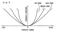
- [FIG. 3] a drawing showing an example of the relationship between steering torque, vehicle speed, and hydraulic fluid pressure in a power steering unit according to an embodiment of the present invention
- [FIG. 4] an explanatory view showing the configuration of a power steering unit according to a first modification of the present invention
- [FIG. 5] an explanatory view showing the configuration of a power steering unit according to a second modification of the present invention
- [FIG. 6] an explanatory view showing the configuration of a power steering unit according to a third modification of the present invention
-
- 10
- hydraulic cylinder
- 13, 14
- oil chamber
- 20
- tank
- 21
- pump
- 22
- motor
- 23
- switching valve
- 32, 33
- check valve
- 40
- torque sensor
- 41
- speed sensor
- 50
- controller
- 60
- flow control valve (motor-operated valve)
- 61
- electromagnetic opening and closing valve (motor-operated valve)
- FIGS. 1 and 2 show a rack and pinion type
power steering apparatus 1 comprising a power steering unit according to the present invention, including aninput shaft 5 connected via auniversal joint 4 to asteering shaft 3 which is connected to asteering wheel 2 of a vehicle. Theinput shaft 5 is supported by a housing 6 through bearings (not shown in the drawings). Theinput shaft 5 is connected to apinion 7, and arack rod 8, on whichrack teeth 8a engaging with thepinion 7 are formed, is connected to the vehicle wheels through tie rods and knuckle arms not shown in the drawings. In this way, therack rod 8 moves due to the rotation of thepinion 7 by the steering operation of thesteering wheel 2, and the movement of therack rod 8 is transmitted to the vehicle wheels to change the steering angle. - The power steering unit includes a
hydraulic cylinder 10 as a hydraulic actuator for generating steering assistance power. Thehydraulic cylinder 10 includes acylinder 11 formed integrally with the housing 6 so as to cover therack rod 8, and apiston 12 integral with therack rod 8. Anoil chamber 13 for generating right steering assistance power and anoil chamber 14 for generating left steering assistance power which are separated by thepiston 12 are formed in the space between the inside surface of thecylinder 11 and the outside surface of therack rod 8, and the ends of therespective oil chambers oil seals rack rod 8 and the inside surface of the housing 6. - The hydraulic fluid for the
hydraulic cylinder 10 is stored in atank 20, and the hydraulic fluid in thetank 20 is discharged by apump 21. Thepump 21 can be, for example, a vane pump or a gear pump, and thepump 21 is driven by anelectric motor 22. - Hydraulic fluid discharged from the
pump 21 is delivered to thehydraulic cylinder 10 via a motor-operatedswitching valve 23. The switchingvalve 23 of the present embodiment is a solenoid valve having aspool 23b which is moved by asolenoid 23a, and the position of thespool 23b is determined alternatively to a right steering assistance position, a left steering assistance position, or a neutral position. By putting thespool 23b in the right steering assistance position, hydraulic fluid flow paths are switched so that hydraulic fluid is led into theoil chamber 13 for generating right steering assistance power from thepump 21 so that the oil pressure rises, and at the same time hydraulic fluid is led from theoil chamber 14 for generating left steering assistance power to thetank 20. By putting thespool 23b in the left steering assistance position, the hydraulic fluid flow paths are switched so that hydraulic fluid is led into theoil chamber 14 for generating left steering assistance power from thepump 21 so that the oil pressure rises, and at the same time hydraulic fluid is led from theoil chamber 13 for generating right steering assistance power to thetank 20. In this way, the right steering assistance power generating state and left steering assistance power generating state can be selected alternatively by switching the hydraulic fluid flow paths with the switchingvalve 23. By putting thespool 23b in the neutral position, bothoil chambers tank 20. - The two
oil chambers hydraulic cylinder 10 are connected via a hydraulic fluid flow path having aninvariable throttle 24 on the outside of thehydraulic cylinder 10. Sudden changes in the steering assistance power are suppressed by theinvariable throttle 24 when there are sudden changes in the hydraulic fluid pressure. The hydraulic fluid flow path having theinvariable throttle 24 can be provided in thepiston 12 of thehydraulic cylinder 10, or it can be omitted since it is not essential. - The discharge side of the
pump 21 and thetank 20 are connected by a hydraulic fluid flow path having arelief valve 20. Therelief valve 20 is closed when the pressure in the discharge side of thepump 21 is below a set value, and the valve opens so that hydraulic fluid discharged from thepump 21 returns to thetank 20 when the pressure becomes the set value or more. - Check
valves respective oil chambers hydraulic cylinder 10 and thetank 20, to check the flow of hydraulic fluid from theoil chambers tank 20, and to allow the flow of hydraulic fluid from thetank 20 to theoil chambers - A
torque sensor 40 which detects the steering torque is provided on theinput shaft 5 as a means for determining the steering direction. The steering direction is determined in accordance with whether the output value is positive or negative, by setting the output value of thetorque sensor 40 to positive value when steering in one of the left and right directions, and setting the output value of thetorque sensor 40 to negative value when steering in the other direction. Thetorque sensor 40 can be a commonly known torque sensor. Thetorque sensor 40 is also used as a means for determining the magnitude of the steering torque as a driving condition of the vehicle. Also, avehicle speed sensor 41 is provided as a means for determining the vehicle driving condition. - The
motor 22, the switchingvalve 23, thetorque sensor 40, and thevehicle speed sensor 41 are connected to acontroller 50. Thetank 20, thepump 21, themotor 22, the switchingvalve 23, and thecontroller 50 are integrated so as to be capable of being attached to and removed from thehydraulic cylinder 10 as a unit via bolts or the like. In this embodiment, the casing of thecontroller 50 is mounted so as to be sandwiched between the casing of themotor 22 and the casing of thepump 21, the casing of the switchingvalve 23 and thetank 20 are mounted on the casing of thepump 21, the rotation shaft of themotor 22 penetrates the casing of thecontroller 50 and is connected to the rotation shaft of thepump 21, and the hydraulic fluid flow paths and theinvariable throttle 24 are formed in the casing of the switchingvalve 23. - The
controller 50 controls the switchingvalve 23 so that the steering assistance power acts in accordance with the steering direction determined from whether the steering torque detected by thetorque sensor 40 is positive or negative, so that thespool 23b moves to the right steering assistance position or the left steering assistance position by the electro-magnetic force of thesolenoid 23a. Further, when the steering torque is not detected, thecontroller 50 moves thespool 23b to the neutral position. Also, thecontroller 50 controls themotor 22 so that the pressure of the hydraulic fluid discharged from thepump 21 is varied in accordance with the magnitude of the steering torque detected by thetorque sensor 40 and the vehicle speed detected by thevehicle speed sensor 41. For example, as shown in FIG. 3, the drive power of themotor 22 is increased to increase the pressure of the hydraulic fluid and steering assistance power as the magnitude of the detected steering torque increases and the detected vehicle speed decreases, and themotor 22 is stopped to cancel the steering assistance power and save energy when the detected steering torque is small and the detected vehicle speed is high. - According to the embodiment as described above, when the steering assistance power is generated by the
hydraulic cylinder 10, the direction of action of the steering assistance power can be changed in accordance with the direction of steering by switching the hydraulic fluid flow paths with using the motor-operatedswitching valve 23, and the steering assistance power can be finely controlled by controlling theelectric motor 22 in accordance with the driving conditions. Also, since thetank 10, thepump 21, themotor 22, the switchingvalve 23, and thecontroller 50 are integrated so as to be capable of being attached to and removed from thehydraulic cylinder 10 as a unit, the efficiency of assembly can be improved. Also, when the pressure in one of theoil chambers hydraulic cylinder 10 to which the hydraulic fluid is to be supplied is negative, hydraulic fluid flows into the oil chamber from thetank 20 through the corresponding one of thecheck valves hydraulic cylinder 10 is prevented and steering assistance power can be rapidly generated. - In a first modification shown in FIG. 4, instead of the
invariable throttle 24 in the embodiment described above, a motor-operatedflow control valve 60 is provided in the flow path between theoil chambers hydraulic cylinder 10 as a motor-operated valve connected to thecontroller 50, so the degree of opening of the hydraulic fluid flow path between thepump 21 and thetank 20 can be varied because theflow control valve 60 serves as a variable throttle. Thecontroller 50 controls themotor 22 and theflow control valve 60 so that the steering assistance power is varied in accordance with the determined driving conditions. For example, when the steering assistance power is being applied, thecontroller 50 controls themotor 22 so that the drive power increases as the magnitude of the detected steering torque increases, and controls theflow control valve 60 so that the degree of opening of the hydraulic fluid flow path reduces as the detected vehicle speed reduces. Alternatively, when the steering assistance power is being applied, thecontroller 50 can drive themotor 22 at a constant output power, and control theflow control valve 60 in accordance with the driving conditions, for example, the degree of opening of the hydraulic fluid flow path is reduced by theflow control valve 60 as the magnitude of the detected steering torque increases and the detected vehicle speed reduces. It is desirable that the motor-operatedflow control valve 60, thetank 20, thepump 21, themotor 22, the switchingvalve 23, and thecontroller 50 are integrated. The rest is the same as the embodiment described above. - In a second modification shown in FIG. 5, instead of the
check valves flow control valves 60 are provided as motor-operated valves in the hydraulic fluid flow paths between theoil chambers tank 20, so the degree of opening of the hydraulic fluid flow path between thepump 21 and thetank 20 can be varied because eachflow control valve 60 serves as a variable throttle. Themotor 22 and theflow control valve 60 connected to the high pressure side of theoil chambers controller 50 in the same way as the first modification, and theflow control valve 60 connected to the low pressure side are controlled so that the degree of opening of the hydraulic fluid flow path is constant, for example, fully open or fully closed. The rest is the same as the embodiment described above. - In a third modification shown in FIG. 6, instead of the
relief valve 31 in the embodiment described above, an electromagnetic opening and closingvalve 61 which acts as a motor-operated valve to open and close the hydraulic fluid flow path, and apressure sensor 62 to detect the pressure in the discharge side of thepump 21 are provided between the discharge side of thepump 21 and thetank 20, so the degree of opening of the hydraulic fluid flow path between thepump 21 and thetank 20 can be varied. The electro-magnetic control valve 61 serves as a relief valve by controlling the electromagnetic opening and closingvalve 61 with thecontroller 50 so that the pressure detected by thepressure sensor 62 in the discharge side of thepump 21 does not become a preset value or more. Also, thecontroller 50 controls themotor 22 and the electromagnetic opening and closingvalve 61 so that the steering assistance power is varied in accordance with the determined driving conditions. For example, when steering assistance power is being applied, thecontroller 50 controls themotor 22 so that the drive power increases as the magnitude of the detected steering torque increases, and controls the electromagnetic opening and closingvalve 61 so that the hydraulic fluid discharge pressure of thepump 21 increases as the detected vehicle speed reduces. Alternatively, when steering assistance power is being applied, thecontroller 50 can drive themotor 22 at a constant output power, and control the electromagnetic opening and closingvalve 61 in accordance with the driving conditions, for example, the electromagnetic opening and closingvalve 61 is controlled so that the detected pressure in the discharge side of thepump 21 increases as the magnitude of the detected steering torque increases and the detected vehicle speed reduces. The rest is the same as the embodiment described above. - The present invention is not limited to the above embodiments. The driving condition to be determined is not limited to steering torque or vehicle speed, for example, the steering angle, steering velocity, or steering acceleration can be determined as a driving condition, and the steering assistance power can be controlled so that the steering assistance power increases as the magnitude of the steering angle, steering velocity, or steering acceleration increases. Also, a steering angle sensor can be provided, and the steering direction can be determined from its detection value. Also, a manual type steering apparatus can be converted into a power steering apparatus by installing the power steering unit of the present invention, for example, by connecting the piston rod of the hydraulic cylinder to the rack of a manual type rack and pinion steering apparatus, fixing the cylinder tube of the hydraulic cylinder to the vehicle body, and mounting the integrated tank, pump, electric motor, switching valve, and controller on the hydraulic cylinder.
Claims (5)
- A power steering unit, comprising:a hydraulic actuator for generating steering assistance power;a tank for storing hydraulic fluid for said hydraulic actuator;a pump for discharging the hydraulic fluid stored in said tank;an electric motor for driving said pump;a motor-operated switching valve which switches the flow path of the hydraulic fluid to said hydraulic actuator so that a state of generating right steering assistance power or a state of generating left steering assistance power is alternatively selected; anda controller which controls said switching valve so that steering assistance power acts in accordance with the determined direction of steering, and controls said motor so that the pressure of the hydraulic fluid discharged from said pump is varied in accordance with the determined driving condition.
- A power steering unit, comprising:a hydraulic actuator for generating steering assistance power;a tank for storing hydraulic fluid for said hydraulic actuator;a pump for discharging the hydraulic fluid stored in said tank;an electric motor which drives said pump;a motor-operated switching valve which switches the flow path of the hydraulic fluid to the hydraulic actuator so that a state of generating right steering assistance power or a state of generating left steering assistance power is alternatively selected;a motor-operated valve which varies the degree of opening of a hydraulic fluid flow path between the discharge side of said pump andsaid tank; anda controller which controls said switching valve so that steering assistance power acts in accordance with the determined direction of steering, and controls said motor-operated valve so that the steering assistance power is varied in accordance with the determined driving condition.
- The power steering unit according to claim 2, wherein said motor is controlled by said controller so that the pressure of the hydraulic fluid discharged from said pump is varied in accordance with the determined driving condition.
- The power steering unit according to any of claims 1 to 3, wherein said tank, said pump, said motor, said switching valve, and said controller are integrated so as to be capable of being attached to and removed from said hydraulic actuator as a unit.
- The power steering unit according to any of claims 1 to 4, wherein said hydraulic actuator has an oil chamber for generating right steering assistance power and an oil chamber for generating left steering assistance power, and check valves are provided on hydraulic fluid flow paths between the respective oil chambers and said tank to check the flow of the hydraulic fluid from each of the oil chambers to said tank and to allow the flow of the hydraulic fluid from said tank to each of the oil chambers.
Applications Claiming Priority (2)
| Application Number | Priority Date | Filing Date | Title |
|---|---|---|---|
| JP2003306679A JP2005075093A (en) | 2003-08-29 | 2003-08-29 | Power steering unit |
| PCT/JP2004/012105 WO2005021357A1 (en) | 2003-08-29 | 2004-08-24 | Power steering unit |
Publications (2)
| Publication Number | Publication Date |
|---|---|
| EP1659047A1 true EP1659047A1 (en) | 2006-05-24 |
| EP1659047A4 EP1659047A4 (en) | 2008-12-24 |
Family
ID=34269401
Family Applications (1)
| Application Number | Title | Priority Date | Filing Date |
|---|---|---|---|
| EP04772066A Withdrawn EP1659047A4 (en) | 2003-08-29 | 2004-08-24 | Power steering unit |
Country Status (4)
| Country | Link |
|---|---|
| US (1) | US20060175118A1 (en) |
| EP (1) | EP1659047A4 (en) |
| JP (1) | JP2005075093A (en) |
| WO (1) | WO2005021357A1 (en) |
Cited By (2)
| Publication number | Priority date | Publication date | Assignee | Title |
|---|---|---|---|---|
| EP2591979A1 (en) | 2011-11-08 | 2013-05-15 | Jtekt Europe | Assistance valve for hydraulic power-steering of an automobile vehicle |
| EP2660126A3 (en) * | 2012-04-10 | 2015-03-11 | Jtekt Corporation | Hydraulic power steering system |
Families Citing this family (11)
| Publication number | Priority date | Publication date | Assignee | Title |
|---|---|---|---|---|
| JP4669800B2 (en) * | 2006-03-09 | 2011-04-13 | 日立オートモティブシステムズ株式会社 | Power steering device |
| ITBO20060424A1 (en) * | 2006-05-31 | 2007-12-01 | Ferrari Spa | STEERING SYSTEM FOR A CAR |
| JP4961521B2 (en) * | 2007-01-23 | 2012-06-27 | 日立オートモティブシステムズ株式会社 | Power steering device |
| US20100018796A1 (en) * | 2008-07-22 | 2010-01-28 | Trw Automotive U.S. Llc | Apparatus for controlling a power-assisted steering gear in response to vehicle conditions |
| JP5888546B2 (en) * | 2011-08-09 | 2016-03-22 | 株式会社ジェイテクト | Hydraulic power steering device |
| KR20150063766A (en) * | 2013-12-02 | 2015-06-10 | 주식회사 두산 | Forklift |
| JP6156221B2 (en) * | 2014-03-26 | 2017-07-05 | 株式会社豊田自動織機 | Industrial vehicle |
| DE102015222864C5 (en) * | 2015-11-19 | 2024-03-07 | Volkswagen Aktiengesellschaft | Servo system and hydraulic steering system for a vehicle |
| DE112017004715B4 (en) * | 2016-09-20 | 2023-02-23 | Knorr-Bremse Steering System Japan Ltd. | POWER STEERING DEVICE |
| CN111301520A (en) * | 2020-03-12 | 2020-06-19 | 洛阳智能农业装备研究院有限公司 | Unmanned agricultural machinery a steering system |
| DE102021103818A1 (en) * | 2021-02-18 | 2022-08-18 | Knorr-Bremse Systeme für Nutzfahrzeuge GmbH | Control device for a vehicle with a steering device, steering device and method for cooling an electric motor for a steering device |
Family Cites Families (17)
| Publication number | Priority date | Publication date | Assignee | Title |
|---|---|---|---|---|
| JPS5536132A (en) * | 1978-09-01 | 1980-03-13 | Toyota Motor Corp | Power steering for vehicle |
| JPS57198169A (en) * | 1981-05-29 | 1982-12-04 | Tokai T R W Kk | Motor-driven oil pressure power steering unit |
| GB2158788B (en) * | 1984-05-05 | 1988-01-27 | Trw Cam Gears Ltd | Power assistance steering systems for vehicles |
| JP3211434B2 (en) * | 1991-12-18 | 2001-09-25 | アイシン精機株式会社 | Vehicle guidance control device |
| US5267627A (en) * | 1992-03-27 | 1993-12-07 | Imra America, Inc. | Vehicle stability augmentation system |
| JPH0655945U (en) * | 1993-01-20 | 1994-08-02 | 株式会社ユニシアジェックス | Power steering pump device |
| US5320191A (en) * | 1993-01-28 | 1994-06-14 | Kabushiki Kaisha Komatsu Seisakusho | Steering circuit system for a moving vehicle |
| JP3339131B2 (en) * | 1993-09-30 | 2002-10-28 | 豊田工機株式会社 | Power steering device |
| JP3196478B2 (en) * | 1994-02-18 | 2001-08-06 | 日産自動車株式会社 | Electric pump type power steering device |
| DE19519875C1 (en) * | 1995-05-31 | 1996-07-04 | Daimler Benz Ag | Hydraulic power steering device for motor vehicle |
| JP3785586B2 (en) * | 1997-06-20 | 2006-06-14 | カヤバ工業株式会社 | Controller for control valve in hydraulic power steering |
| JP3815885B2 (en) * | 1998-04-28 | 2006-08-30 | 日本電産株式会社 | Pump device |
| US6173223B1 (en) * | 1999-01-05 | 2001-01-09 | Ford Global Technologies, Inc. | Steering control method for providing variable assist power steering |
| US6419042B1 (en) * | 2000-10-03 | 2002-07-16 | Trw Inc. | Integrated electric power hydraulic steering system |
| JP4075326B2 (en) * | 2001-05-28 | 2008-04-16 | ユニシア ジェーケーシー ステアリングシステム株式会社 | Steering damper |
| DE10163153A1 (en) * | 2001-12-20 | 2003-07-03 | Siemens Ag | Method for controlling a safety-critical system containing a microcontroller |
| JP4215662B2 (en) * | 2004-03-08 | 2009-01-28 | 株式会社日立製作所 | Power steering device |
-
2003
- 2003-08-29 JP JP2003306679A patent/JP2005075093A/en active Pending
-
2004
- 2004-08-24 US US10/569,241 patent/US20060175118A1/en not_active Abandoned
- 2004-08-24 EP EP04772066A patent/EP1659047A4/en not_active Withdrawn
- 2004-08-24 WO PCT/JP2004/012105 patent/WO2005021357A1/en not_active Ceased
Cited By (3)
| Publication number | Priority date | Publication date | Assignee | Title |
|---|---|---|---|---|
| EP2591979A1 (en) | 2011-11-08 | 2013-05-15 | Jtekt Europe | Assistance valve for hydraulic power-steering of an automobile vehicle |
| EP2660126A3 (en) * | 2012-04-10 | 2015-03-11 | Jtekt Corporation | Hydraulic power steering system |
| US9079609B2 (en) | 2012-04-10 | 2015-07-14 | Jtekt Corporation | Hydraulic power steering system |
Also Published As
| Publication number | Publication date |
|---|---|
| US20060175118A1 (en) | 2006-08-10 |
| WO2005021357A1 (en) | 2005-03-10 |
| JP2005075093A (en) | 2005-03-24 |
| EP1659047A4 (en) | 2008-12-24 |
Similar Documents
| Publication | Publication Date | Title |
|---|---|---|
| EP1659047A1 (en) | Power steering unit | |
| EP2805871B1 (en) | Power steering system | |
| US7325645B2 (en) | Power steering device | |
| JP5323753B2 (en) | Construction machine control equipment | |
| CA2878141C (en) | Actuator | |
| KR20140010046A (en) | Hydraulic device for actuating a clutch | |
| US5161865A (en) | Hydraulic modulator with working piston connected to control piston | |
| US20050160851A1 (en) | Hydraulic power assisted steering system | |
| US5785144A (en) | Power steering system/servo control | |
| CN100551759C (en) | Variable gear ratio hydraulic power steering device | |
| EP2591978A2 (en) | Power steering system | |
| JPH03501597A (en) | Automotive hydraulic power steering system | |
| US20090223737A1 (en) | Power Assisted Steering System | |
| JP4704259B2 (en) | Energy converter | |
| JPS59118569A (en) | Power steering gear for vehicle | |
| JP2015160447A (en) | power steering device | |
| JP3994045B2 (en) | Flow control device | |
| KR101703375B1 (en) | Control device for a hydraulic motor and hydraulic motor assembly | |
| WO2012021184A1 (en) | Power steering system | |
| CN101056791A (en) | Steering system for motor vehicle | |
| US20110286862A1 (en) | Pump for a lubricating system of a combustion engine | |
| KR100475921B1 (en) | fluid flow control device of hydraulic steering system | |
| KR100622120B1 (en) | Power steering gear of car | |
| JP2696336B2 (en) | Power steering device | |
| KR100375056B1 (en) | Hydraulic power unit for vehicle power steering |
Legal Events
| Date | Code | Title | Description |
|---|---|---|---|
| PUAI | Public reference made under article 153(3) epc to a published international application that has entered the european phase |
Free format text: ORIGINAL CODE: 0009012 |
|
| 17P | Request for examination filed |
Effective date: 20060301 |
|
| AK | Designated contracting states |
Kind code of ref document: A1 Designated state(s): DE FR GB IT |
|
| RAP1 | Party data changed (applicant data changed or rights of an application transferred) |
Owner name: JTEKT CORPORATION |
|
| DAX | Request for extension of the european patent (deleted) | ||
| RBV | Designated contracting states (corrected) |
Designated state(s): DE FR GB IT |
|
| A4 | Supplementary search report drawn up and despatched |
Effective date: 20081121 |
|
| STAA | Information on the status of an ep patent application or granted ep patent |
Free format text: STATUS: THE APPLICATION IS DEEMED TO BE WITHDRAWN |
|
| 18D | Application deemed to be withdrawn |
Effective date: 20090220 |