EP1658587B1 - Online wavefront measurement and display - Google Patents
Online wavefront measurement and display Download PDFInfo
- Publication number
- EP1658587B1 EP1658587B1 EP04763406.8A EP04763406A EP1658587B1 EP 1658587 B1 EP1658587 B1 EP 1658587B1 EP 04763406 A EP04763406 A EP 04763406A EP 1658587 B1 EP1658587 B1 EP 1658587B1
- Authority
- EP
- European Patent Office
- Prior art keywords
- centroid
- image
- algorithm
- wavefront
- centroids
- Prior art date
- Legal status (The legal status is an assumption and is not a legal conclusion. Google has not performed a legal analysis and makes no representation as to the accuracy of the status listed.)
- Expired - Lifetime
Links
Images


Classifications
-
- G—PHYSICS
- G06—COMPUTING OR CALCULATING; COUNTING
- G06T—IMAGE DATA PROCESSING OR GENERATION, IN GENERAL
- G06T7/00—Image analysis
- G06T7/0002—Inspection of images, e.g. flaw detection
- G06T7/0012—Biomedical image inspection
-
- A—HUMAN NECESSITIES
- A61—MEDICAL OR VETERINARY SCIENCE; HYGIENE
- A61B—DIAGNOSIS; SURGERY; IDENTIFICATION
- A61B3/00—Apparatus for testing the eyes; Instruments for examining the eyes
- A61B3/10—Objective types, i.e. instruments for examining the eyes independent of the patients' perceptions or reactions
-
- A—HUMAN NECESSITIES
- A61—MEDICAL OR VETERINARY SCIENCE; HYGIENE
- A61B—DIAGNOSIS; SURGERY; IDENTIFICATION
- A61B3/00—Apparatus for testing the eyes; Instruments for examining the eyes
- A61B3/0016—Operational features thereof
- A61B3/0025—Operational features thereof characterised by electronic signal processing, e.g. eye models
-
- G—PHYSICS
- G06—COMPUTING OR CALCULATING; COUNTING
- G06T—IMAGE DATA PROCESSING OR GENERATION, IN GENERAL
- G06T7/00—Image analysis
- G06T7/60—Analysis of geometric attributes
- G06T7/66—Analysis of geometric attributes of image moments or centre of gravity
-
- G—PHYSICS
- G06—COMPUTING OR CALCULATING; COUNTING
- G06T—IMAGE DATA PROCESSING OR GENERATION, IN GENERAL
- G06T2207/00—Indexing scheme for image analysis or image enhancement
- G06T2207/30—Subject of image; Context of image processing
- G06T2207/30004—Biomedical image processing
- G06T2207/30041—Eye; Retina; Ophthalmic
Definitions
- Embodiments of the invention are generally directed to the field of image processing, and more particularly to methods and apparatus for the simultaneous measurement, analysis, and display of ocular wavefront information referred to herein as "online" aberrometry.
- aberrometers which incorporate wavefront sensors can provide information about vision defects that, upon correction, may not only provide visual acuity at the theoretical limit but also better vision, perhaps even customized vision, under a panoply of viewing conditions.
- a Hartman-Shack wavefront sensor typically includes a microlens array that images various portions of a distorted wavefront exiting the eye onto a CCD detector/camera.
- the image produced by the microlens array comprises an array of small dots of light that are slightly displaced from reference locations of the light dot image from an unaberrated wavefront.
- the aberrated dot displacements are related to the localized slopes of the wavefront exiting the eye's pupil.
- Zernike polynomials or other mathematical forms
- the ability to make accurate wavefront calculations is critically dependent upon the true determination of the center location of each dot in the wavefront image. This aspect of the wavefront analysis process is known as centroid detection.
- Hartmann-Shack wavefront sensors typically measure single images of centroids or, at best, a very small number of images over a short time interval.
- the eye is a dynamic system with rapidly varying wavefront changes.
- the time needed for centroid detection has been the primary culprit hindering real-time measurements with repetition rates greater than a few images per second.
- a system known in the wavefront art as WASCA has demonstrated a repetition rate of about 7Hz for the 30-second record of a wavefront.
- WASCA has demonstrated a repetition rate of about 7Hz for the 30-second record of a wavefront.
- the wavefront images must first be recorded, saved, and subsequently evaluated.
- a single wavefront image requires about 400Kb of computer memory.
- An embodiment of the present invention is directed to an algorithm that provides for the detection of bright and dark structures in a CCD image.
- the image may comprise, for illustration purposes only, centroids in a wavefront image, or identified markings on a contact lens surface.
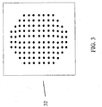
- Figure 3 illustrates an array of centroid images 32 as black spots in a simulated Hartmann-Shack wavefront image.
- a feature of this embodiment is that the positions of structures such as centroids 32 in a CCD image, for example, can be located and sorted in approximately 5ms, Zernike coefficients calculated, and wavefront image information displayed in approximately 13ms or less (utilizing an 800MHz Pentium® (Intel) processor or equivalent).
- a 1.6GHz processor would reduce the total time by approximately one-half by increasing the rate to approximately 50Hz.
- the algorithm thus describes what is referred to throughout this description as "online" analysis of wavefront information, referring to the detection, measurement, and display of wavefront information substantially simultaneously at a rate up to approximately 25Hz.
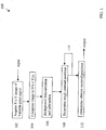
- a method for centroid detection in a wavefront image is set forth in the flow chart diagram 100 of Figure 1 . It is noted at the outset that in the illustrated embodiment, a sequential plurality of images are acquired, analyzed, and displayed as desired at a rate of 25hz, but for the sake of simplicity the algorithm steps set forth below apply to a single wavefront image and are repeated for every wavefront image of the desired sequence.
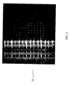
- an X x Y pixel size wavefront image is acquired.
- the light spot images are represented by variable pixel signal intensities as shown.
- Images taken from a CCD camera usually consist of an array of pixels in which every pixel is assigned a number proportional to the amount of charge collected at this pixel. This number is referred to as the signal of the pixel.
- the signal of the pixel In the illustrative description that follows, a regular square grid of bright points in a dark image will be described in detail.
- the image is compressed from size X x Y pixels to X/n x Y/m pixels at step 104. This can be done by averaging the signal for every pixel in an n x m pixel square in the original image starting, for example, in the upper left corner of the image and scanning through the image. The signal in the upper left corner of the compressed image is then set to the average of the first square, the signal of the next pixel is set to the average of the next (second) square, and so on, finally yielding a picture X/n x Y/m pixels in size.
- the compressed image is then divided into square regions, or tiles (not to be confused with the pixel squares in (i) above).
- one tile is a square of 64x64 pixels, but other sizes can be used.
- one tile might contain 3-5 centroids.
- the average signal is again calculated for every tile.
- the average values for the tiles are then linearly extrapolated to yield a background value for any location in the image. This background is then subtracted from the image yielding a low signal outside the centroids.
- a signal-to-noise ratio of two was improved to a signal-to-noise ratio of 10 by the background subtraction.
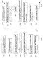
- the approximate, or rough, structure points are identified.
- a maximum is defined as the highest signal in the compressed image. The maximum is determined by a scan through the image, and the X-position, Y-position, and signal value of every pixel is recorded in a table, but only if the signal value of this point is greater than a certain percentage of the maximum, e.g., 30 % (other values can be selected by the user). In the exemplary embodiment, this yields a table (Table I) of about 400 entries. The table is sorted by descending signal as shown. Any of a variety of quick sorting routines is available to accomplish this. TABLE I Signal X Position Y Position 223 86 55 154 85 75 135 87 95 133 115 56 110 118 74 108 114 93 . . . . . . .
- the first entry (highest signal value) is defined as the first rough structure point.
- all entries in the table that obey a certain pre-set condition are defined as rough structure points.
- the pre-set condition is that the position of the particular entry is farther away from all yet found rough structure points than a pre-set distance. In an exemplary embodiment, the distance is 17 pixels.
- step 108 can be repeated as shown at block 110, setting a new minimum to a certain percentage of the minimum in the first iteration.
- the second iteration finds points that were too weak in signal to be found in the first iteration.
- the rough structure points found in the first iteration are accounted for so they will not be found again (i.e., they do not obey the condition of being farther away than a pre-set distance from the detected points).
- the ultimate centroid positions are determined. Since the image was earlier compressed in step 104, much of the information originally contained in the image was ignored. This information can now be used to determine more exact centroid positions. Using the original uncompressed image, a square of, for example, 15x15 pixels is created around every rough point. Generally, each square is smaller than 2x the minimum distance to insure that each square contains only one centroid, and is larger than the centroid itself. In the exemplary embodiment this value is between five and 30 pixels. Then, the center of mass of signal for the signal distribution inside the square is determined, giving rise to the substantially exact position of the centroid.
- step 112 can be repeated, for example, 1, 2, 3...n times to determine still more exact results.
- the calculated center of mass in the previous step is subsequently used.
- Each structure point can also be assigned a quality factor depending on how much the position of the center of mass changes if the square around the pixel is willingly shifted by a user-set distance, at step 112. In an exemplary embodiment, this distance is five pixels.
- the points whose positions have changed the least are assigned the highest quality factors. In this manner, spurious points or noise assigned a low quality factor can be eliminated, as they likely represent false structure points.
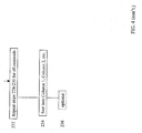
- an aspect 200 of the embodiment as illustrated in Figure 4 is directed to the process of sorting the detected centroids so as to assign them to a regular square grid pattern. It will be appreciated by those skilled in the art that the algorithm can be easily adapted to other structures or configurations such as, for example, points on rings, or any straight line of points.
- the desired sorting configuration is selected.
- the configuration is a square grid based upon the geometry of the microlens array. For every previously found centroid point, i, the formula for a straight line is calculated containing the centroid point, i, and having a slope of 1 (45°), as shown at step 204. For starting positions of the upper left corner or lower right corner of the image, slope values between 0.1 to 0.9 can be used. Likewise, when the starting position is the upper right corner or the lower left corner of the image, slope values from -0.1 to -0.9 can be selected.
- the distance 502 (n i ), between the line 514 and, in the illustrative embodiment, the upper left corner 506 of the image 510 is calculated, as illustrated in Fig. 5 .
- All centroids, i are then sorted by n i at step 208 starting with the centroid having the smallest n i value.
- the centroid with the smallest n i value is assigned to Row 1 and is stored in memory as the last centroid of Row 1. In an aspect of the embodiment, the last centroids of the existing rows are stored in memory during step 210.
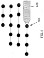
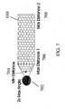
- a region 610 is defined that, in an exemplary embodiment, comprises an area to the right of the last centroid 605 of a given row, having dimensions that can be controlled and varied by parameters of the lenslet array, and having a shape that is suited to detecting the selected grid configuration, as illustrated in Figure 6 , which shows the search area 610 for the next centroid. Any shape suited for detecting other grid configurations is alternatively possible. Examples of the lenslet array parameters include maximum angle 702, minimum distance 704, maximum distance 1 (706), and maximum distance 2 (708), as illustrated in Figure 7 . Then, at step 214, the next higher n i value is selected and that centroid is checked, with respect to all existing rows, whether the centroid is in the defined region.
- Step 216 that centroid is assigned as the last centroid of that row. If no, than that centroid is assigned the last centroid of a new row. Steps 214-216 are now repeated for all centroids. In this manner, rows start to build up from left to right.
- the average y-position for each row is calculated and the rows are sorted according to their average y-position. This step facilitates marking of the top row as Row 1, the next row as Row 2, and so on.
- step 222 involves merging these rows.
- the criteria for merging rows j and k is: If y j -y k ⁇ f*a and (P k,first > P j,last or P k,last ⁇ P j,first ), where:
- the process for sorting the columns begins at step 224 where the list of sorted centroids by distance value from step 208 is used again.
- the centroid with the smallest n i is assigned to Column 1 and is stored in memory as the last centroid of Column 1.
- the last centroids of an existing column are always stored in memory during step 224.
- a region is defined that, in the exemplary embodiment, comprises an area below the last centroid of a given column having dimensions and shape that are controlled and varied by the same parameters of the lenslet array as set forth above. This is illustrated by tilting the diagram in Figure 6 downward by 90 degrees.
- the next higher n i value is selected and that centroid is checked, with respect to all existing columns, whether the centroid is in the defined region.
- Step 230 that centroid is assigned as the last centroid of that column. If no, than that centroid is assigned the last centroid of a new column. Steps 228-230 are now repeated for all centroids. In this manner, columns start to build up from top to bottom.
- step 234 the average x-position for each column is calculated and the columns are sorted according to their average x-position. This step facilitates marking of the left-most column as Column 1, the next column as Column 2, and so on.
- step 236 involves merging these columns. This is accomplished by the following sub-steps: From the mean average x-position for each column from step 228, calculate the mean distance between the columns by subtracting x column1 -x column2 (yielding the distance between Column1 and Column2); x column2 -x column3 (yielding the distance between Column2 and Column3); and so on, and then taking the mean values of the obtained distances.
- the criteria for merging columns j and k is: If x j -x k ⁇ f*a and (P k,first > P j,last or P k,last ⁇ P j,first ), where:
- a Zernike calculation can be made to determine the wavefront aberration.
- the processes for acquiring a single image and displaying the wavefront aberration information, using an 800MHz Pentium processor are listed below with their corresponding processing times: Finding and sorting the centroids: ⁇ 5ms; Performing the Zernike calculations: ⁇ 5ms; Imaging operations: ⁇ 8ms; Image display: ⁇ 8ms Pupil coordinate location (optional): ⁇ 6-8ms; Contact lens position (optional): ⁇ 5ms
- the Zernike calculation process is performed twice during a measurement cycle, once for the second-order terms and once for the higher-order terms.
- the total time per image is approximately 40ms or slightly less at a repetition rate of 25Hz.
- conventional real-time (as opposed to online) wavefront analysis consists of storing a sequence of images and subsequently analyzing the images for wavefront information. These techniques are limited by computer storage requirements. For example, storing two images at 25Hz for 30 seconds requires approximately 400MB/measurement.
- the storage of images is not necessary because the information contained in those images has already been extracted by detecting the centroid and pupil position. Storing only pupil and centroid position data results in data storage requirements of only about 700Kb of memory for a 20 second measurement at 25Hz, which will yield 500 images.
- Another embodiment of the invention is directed to a device-readable medium that has stored thereon an executable instruction for carrying out the algorithm described above.
- Appropriate media are well known and include, without limitation, CD, DVD, diskette, hard drive, carrier wave, and others.
- Another embodiment of the invention is directed to a method for wavefront analysis.
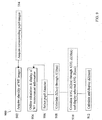
- the method is set forth in the block diagram of Figure 9 .
- the method comprises at step 902 acquiring a plurality of wavefront images of light exiting a pupil of an eye, where each of the images includes a displaced centroid that is indicative of wavefront measurement information of the eye, and at step 904 calculating and displaying the wavefront measurement information online for a selected aberration order.
- the term "online” refers to the substantially simultaneous measurement, analysis, and display of the wavefront measurement information.
- the exemplary fast algorithm described in the previous embodiment is but one way to facilitate an online process. Persons skilled in the art will appreciate that other algorithms can be developed, or are currently available, that will also facilitate the online technique.
- the images are acquired at a rate equal to or greater than 10Hz. In an exemplary aspect, the images are obtained at a rate of 25Hz; however, computer processor speed is the limiting factor in the image acquisition rate. In another aspect, at least 50 sequential images are acquired.
- the step 906 of calculating and displaying the wavefront measurement information online for a selected aberration order is performed for a selected pupil diameter. That is to say, if a pupil diameter value is not selected prior to the measurement, the display will be limited to second order aberrations (sphere or spherical equivalent, and cylinder/axis) because second order aberrations are pupil diameter independent.
- a pupil diameter value can be selected prior to measurement allowing any Zernike order (e.g., coma, spherical aberration, higher-orders) for that given diameter to be displayed online.
- An exemplary range of pupil diameters is between about 2mm to 10mm.
- 500 images can be obtained (and thus 500 measurements can be made) over a 20-second time interval.
- the first 125 images might be obtained for pupil diameter, D ⁇ D min ; the next 250 images for D min ⁇ D ⁇ D max ; and the remaining 125 images for D max ⁇ D.
- Zernike amplitudes for Z 2xx through Z 10xx can be calculated as set forth at step 908.
- an average value of a selected Zernike order can be calculated and displayed online. If an average value has been calculated, well known statistical techniques can be used to determine a standard deviation at step 912 that provides an error band for the average wavefront measurement.
- blinking periods can be determined which contain anomalous wavefront information, and the information during these blinking periods discarded.
- contact lens position were being measured, for example, it would be advantageous to eliminate measurements during blinking periods as lens settlement takes a short time to occur. Knowing the value of the most frequently occurring wavefront amplitude for a particular aberration order based upon pupil diameter will allow the practitioner to prescribe a treatment or vision correction resulting in optimum vision for the patient.
- a sequence of pupil images corresponding to the wavefront images can also be obtained. These images can be saved simultaneously so that the influence of eye movement on changes in the wavefront can be evaluated.
- the apparatus includes an illumination component 1010 that delivers a small spot of light onto the retina of the eye 1020, an imaging component 1030 that forms a centroid image of the illumination light scattered from the retina and exiting the pupil of the eye, a detector 1040 adapted to acquire the centroid image, a processor 1050 working in cooperation with the detector that executes a centroid displacement calculation to determine the wavefront measurement information, a display component 1060 operatively connected to the processor that displays a selected wavefront measurement information, and means 1070 for instructing an online calculation and display of the selected wavefront measurement information.
- An optional pupil camera 1080 and pupilometer 1090 is also shown, where components 1015 are beam splitters or optical equivalents thereof.
Landscapes
- Engineering & Computer Science (AREA)
- Health & Medical Sciences (AREA)
- Life Sciences & Earth Sciences (AREA)
- Physics & Mathematics (AREA)
- General Health & Medical Sciences (AREA)
- Medical Informatics (AREA)
- Theoretical Computer Science (AREA)
- General Physics & Mathematics (AREA)
- Computer Vision & Pattern Recognition (AREA)
- Veterinary Medicine (AREA)
- Biophysics (AREA)
- Animal Behavior & Ethology (AREA)
- Molecular Biology (AREA)
- Public Health (AREA)
- Heart & Thoracic Surgery (AREA)
- Surgery (AREA)
- Biomedical Technology (AREA)
- Ophthalmology & Optometry (AREA)
- Geometry (AREA)
- Signal Processing (AREA)
- Nuclear Medicine, Radiotherapy & Molecular Imaging (AREA)
- Radiology & Medical Imaging (AREA)
- Quality & Reliability (AREA)
- Image Analysis (AREA)
- Eye Examination Apparatus (AREA)
- Testing Of Optical Devices Or Fibers (AREA)
- Image Processing (AREA)
- Length Measuring Devices By Optical Means (AREA)
Applications Claiming Priority (2)
| Application Number | Priority Date | Filing Date | Title |
|---|---|---|---|
| DE10333813A DE10333813A1 (de) | 2003-07-24 | 2003-07-24 | Online-Wellenfrontmessung und Anzeige |
| PCT/EP2004/008205 WO2005015495A2 (en) | 2003-07-24 | 2004-07-22 | Online wavefront measurement and display |
Publications (2)
| Publication Number | Publication Date |
|---|---|
| EP1658587A2 EP1658587A2 (en) | 2006-05-24 |
| EP1658587B1 true EP1658587B1 (en) | 2018-09-19 |
Family
ID=34071891
Family Applications (1)
| Application Number | Title | Priority Date | Filing Date |
|---|---|---|---|
| EP04763406.8A Expired - Lifetime EP1658587B1 (en) | 2003-07-24 | 2004-07-22 | Online wavefront measurement and display |
Country Status (11)
| Country | Link |
|---|---|
| US (1) | US7708411B2 (enExample) |
| EP (1) | EP1658587B1 (enExample) |
| JP (1) | JP2006528499A (enExample) |
| KR (1) | KR20060080578A (enExample) |
| CN (1) | CN1856803A (enExample) |
| AU (1) | AU2004263957B2 (enExample) |
| CA (1) | CA2539944A1 (enExample) |
| DE (1) | DE10333813A1 (enExample) |
| ES (1) | ES2689935T3 (enExample) |
| SG (1) | SG145707A1 (enExample) |
| WO (1) | WO2005015495A2 (enExample) |
Families Citing this family (11)
| Publication number | Priority date | Publication date | Assignee | Title |
|---|---|---|---|---|
| DE10333794A1 (de) | 2003-07-24 | 2005-03-03 | Technovision Gmbh | Verfahren und Vorrichtung zur Online-Kontaktlinsenbewertung |
| US7789513B2 (en) | 2007-04-20 | 2010-09-07 | Alcon Refractivehorizons, Inc. | Adaptive wavefront modulation system and method for refractive laser surgery |
| CN101055223B (zh) * | 2007-04-26 | 2010-12-08 | 中国科学院光电技术研究所 | 哈特曼波前传感器质心测量精度优化方法 |
| US8740381B2 (en) * | 2007-06-27 | 2014-06-03 | Bausch & Lomb Incorporated | Method and apparatus for extrapolating diagnostic data |
| DE102008014294A1 (de) * | 2008-03-14 | 2009-09-17 | Bausch & Lomb Inc. | Schneller Algorithmus für Wellenfrontdatenstrom |
| US8254724B2 (en) * | 2008-11-06 | 2012-08-28 | Bausch & Lomb Incorporated | Method and apparatus for making and processing aberration measurements |
| US9504376B2 (en) * | 2009-12-22 | 2016-11-29 | Amo Wavefront Sciences, Llc | Optical diagnosis using measurement sequence |
| CN104103078A (zh) * | 2014-07-31 | 2014-10-15 | 中国航天科工集团第三研究院第八三五七研究所 | 一种螺旋对称中心检测方法 |
| CN104955148B (zh) * | 2014-12-09 | 2019-03-19 | 文春明 | 一种利用电磁波对称传播特性的无线传感网络定位方法 |
| US9782064B1 (en) | 2016-04-08 | 2017-10-10 | Clarity Medical Systems, Inc. | Obtaining and displaying histogram and/or confidence of intra-operative refraction and/or IOL power recommendation |
| CN106530278B (zh) * | 2016-10-14 | 2020-01-07 | 中国科学院光电技术研究所 | 用于点源哈特曼波前探测器的点光斑检测与背景噪声特征估计方法 |
Family Cites Families (5)
| Publication number | Priority date | Publication date | Assignee | Title |
|---|---|---|---|---|
| DE4222395A1 (de) | 1992-07-08 | 1994-01-13 | Amtech Ges Fuer Angewandte Mic | Vorrichtung und Verfahren zur Messung der Augenrefraktion |
| US5777719A (en) | 1996-12-23 | 1998-07-07 | University Of Rochester | Method and apparatus for improving vision and the resolution of retinal images |
| FR2788597B1 (fr) | 1999-01-15 | 2001-02-23 | Imagine Optic Sarl | Procede et dispositif d'analyse de front d'onde a grande dynamique |
| US6234631B1 (en) | 2000-03-09 | 2001-05-22 | Lasersight Technologies, Inc. | Combination advanced corneal topography/wave front aberration measurement |
| DE10154194A1 (de) | 2001-11-07 | 2003-05-22 | Asclepion Meditec Ag | Verfahren und Vorrichtung zur Messung des Dynamischen Verhaltens eines optischen Systems |
-
2003
- 2003-07-24 DE DE10333813A patent/DE10333813A1/de not_active Withdrawn
-
2004
- 2004-07-22 WO PCT/EP2004/008205 patent/WO2005015495A2/en not_active Ceased
- 2004-07-22 AU AU2004263957A patent/AU2004263957B2/en not_active Ceased
- 2004-07-22 SG SG200805750-7A patent/SG145707A1/en unknown
- 2004-07-22 CA CA002539944A patent/CA2539944A1/en not_active Abandoned
- 2004-07-22 ES ES04763406.8T patent/ES2689935T3/es not_active Expired - Lifetime
- 2004-07-22 JP JP2006520794A patent/JP2006528499A/ja active Pending
- 2004-07-22 KR KR1020067001479A patent/KR20060080578A/ko not_active Ceased
- 2004-07-22 US US10/565,703 patent/US7708411B2/en active Active
- 2004-07-22 EP EP04763406.8A patent/EP1658587B1/en not_active Expired - Lifetime
- 2004-07-22 CN CNA2004800274699A patent/CN1856803A/zh active Pending
Non-Patent Citations (1)
| Title |
|---|
| None * |
Also Published As
| Publication number | Publication date |
|---|---|
| JP2006528499A (ja) | 2006-12-21 |
| WO2005015495A2 (en) | 2005-02-17 |
| WO2005015495A3 (en) | 2005-12-22 |
| EP1658587A2 (en) | 2006-05-24 |
| AU2004263957B2 (en) | 2010-05-13 |
| US20070008491A1 (en) | 2007-01-11 |
| AU2004263957A1 (en) | 2005-02-17 |
| CN1856803A (zh) | 2006-11-01 |
| ES2689935T3 (es) | 2018-11-16 |
| KR20060080578A (ko) | 2006-07-10 |
| CA2539944A1 (en) | 2005-02-17 |
| DE10333813A1 (de) | 2005-02-17 |
| SG145707A1 (en) | 2008-09-29 |
| US7708411B2 (en) | 2010-05-04 |
Similar Documents
| Publication | Publication Date | Title |
|---|---|---|
| CA2533068C (en) | Method and apparatus for online contact lens evaluation | |
| EP1658587B1 (en) | Online wavefront measurement and display | |
| CN104697476B (zh) | 粗糙度光切轮廓曲线的自动检测方法及装置 | |
| WO2020253827A1 (zh) | 评估图像采集精度的方法及装置、电子设备和存储介质 | |
| GB2591910A (en) | Preprocessing method for performing quantitative analysis on fundus image, and storage device | |
| JP5583980B2 (ja) | 画像処理方法および画像処理装置 | |
| US8254724B2 (en) | Method and apparatus for making and processing aberration measurements | |
| JP2002000567A (ja) | 瞳孔中心位置計測方法及び視点位置検出方法 | |
| JP2006528499A5 (enExample) | ||
| JP2002102172A (ja) | 視線検出方法及びシステム | |
| CN118161124A (zh) | 基于自适应非线性滤波器的双目瞳孔直径测量方法及系统 | |
| CN114093018B (zh) | 一种基于瞳孔定位的视力筛查设备及系统 | |
| JP2022548111A (ja) | 涙液層破壊を検出するための装置および方法 | |
| WO2014179728A1 (en) | Methods and apparatuses for determning contact lens intolerance in contact lens wearer patients based on dry eye tear film characteristic analysis and dry eye symptoms | |
| JP7631780B2 (ja) | 眼球運動計測装置、眼球運動計測方法及びプログラム | |
| EP2229092B1 (en) | Aberrometer having reduced noise | |
| CN117422758A (zh) | 虹膜直径的获取方法、装置、电子设备及存储介质 | |
| CN119092112A (zh) | 视力筛查评估数据的处理方法、系统、设备及存储介质 | |
| CN121033159A (zh) | 一种铝电解槽测量的图像处理方法、装置及测量设备 | |
| CN120510201A (zh) | 一种角膜曲率半径计算方法、系统和验光仪 | |
| JP2018504198A (ja) | 角膜内皮の細胞の形態計測的解析のための方法および装置 | |
| KR20180047591A (ko) | 검안기 및 검안기의 영상처리방법 |
Legal Events
| Date | Code | Title | Description |
|---|---|---|---|
| PUAI | Public reference made under article 153(3) epc to a published international application that has entered the european phase |
Free format text: ORIGINAL CODE: 0009012 |
|
| 17P | Request for examination filed |
Effective date: 20060217 |
|
| AK | Designated contracting states |
Kind code of ref document: A2 Designated state(s): AT BE BG CH CY CZ DE DK EE ES FI FR GB GR HU IE IT LI LU MC NL PL PT RO SE SI SK TR |
|
| AX | Request for extension of the european patent |
Extension state: AL HR LT LV MK |
|
| DAX | Request for extension of the european patent (deleted) | ||
| RBV | Designated contracting states (corrected) |
Designated state(s): DE ES FR GB IT |
|
| 17Q | First examination report despatched |
Effective date: 20061103 |
|
| RIN1 | Information on inventor provided before grant (corrected) |
Inventor name: POLLAND, HANS-JOACHIM Inventor name: SEITZ, STEFAN Inventor name: YOUSSEFI, GERHARD |
|
| GRAP | Despatch of communication of intention to grant a patent |
Free format text: ORIGINAL CODE: EPIDOSNIGR1 |
|
| INTG | Intention to grant announced |
Effective date: 20180314 |
|
| GRAJ | Information related to disapproval of communication of intention to grant by the applicant or resumption of examination proceedings by the epo deleted |
Free format text: ORIGINAL CODE: EPIDOSDIGR1 |
|
| GRAR | Information related to intention to grant a patent recorded |
Free format text: ORIGINAL CODE: EPIDOSNIGR71 |
|
| GRAS | Grant fee paid |
Free format text: ORIGINAL CODE: EPIDOSNIGR3 |
|
| GRAA | (expected) grant |
Free format text: ORIGINAL CODE: 0009210 |
|
| INTC | Intention to grant announced (deleted) | ||
| AK | Designated contracting states |
Kind code of ref document: B1 Designated state(s): DE ES FR GB IT |
|
| INTG | Intention to grant announced |
Effective date: 20180813 |
|
| REG | Reference to a national code |
Ref country code: GB Ref legal event code: FG4D |
|
| REG | Reference to a national code |
Ref country code: DE Ref legal event code: R096 Ref document number: 602004053204 Country of ref document: DE |
|
| REG | Reference to a national code |
Ref country code: ES Ref legal event code: FG2A Ref document number: 2689935 Country of ref document: ES Kind code of ref document: T3 Effective date: 20181116 |
|
| REG | Reference to a national code |
Ref country code: DE Ref legal event code: R097 Ref document number: 602004053204 Country of ref document: DE |
|
| PLBE | No opposition filed within time limit |
Free format text: ORIGINAL CODE: 0009261 |
|
| STAA | Information on the status of an ep patent application or granted ep patent |
Free format text: STATUS: NO OPPOSITION FILED WITHIN TIME LIMIT |
|
| 26N | No opposition filed |
Effective date: 20190620 |
|
| P01 | Opt-out of the competence of the unified patent court (upc) registered |
Effective date: 20230503 |
|
| P02 | Opt-out of the competence of the unified patent court (upc) changed |
Effective date: 20230524 |
|
| PGFP | Annual fee paid to national office [announced via postgrant information from national office to epo] |
Ref country code: IT Payment date: 20230620 Year of fee payment: 20 Ref country code: FR Payment date: 20230621 Year of fee payment: 20 |
|
| PGFP | Annual fee paid to national office [announced via postgrant information from national office to epo] |
Ref country code: GB Payment date: 20230620 Year of fee payment: 20 Ref country code: ES Payment date: 20230801 Year of fee payment: 20 |
|
| PGFP | Annual fee paid to national office [announced via postgrant information from national office to epo] |
Ref country code: DE Payment date: 20230620 Year of fee payment: 20 |
|
| REG | Reference to a national code |
Ref country code: DE Ref legal event code: R071 Ref document number: 602004053204 Country of ref document: DE |
|
| REG | Reference to a national code |
Ref country code: ES Ref legal event code: FD2A Effective date: 20240730 |
|
| REG | Reference to a national code |
Ref country code: GB Ref legal event code: PE20 Expiry date: 20240721 |
|
| PG25 | Lapsed in a contracting state [announced via postgrant information from national office to epo] |
Ref country code: GB Free format text: LAPSE BECAUSE OF EXPIRATION OF PROTECTION Effective date: 20240721 |
|
| PG25 | Lapsed in a contracting state [announced via postgrant information from national office to epo] |
Ref country code: ES Free format text: LAPSE BECAUSE OF EXPIRATION OF PROTECTION Effective date: 20240723 |
|
| PG25 | Lapsed in a contracting state [announced via postgrant information from national office to epo] |
Ref country code: GB Free format text: LAPSE BECAUSE OF EXPIRATION OF PROTECTION Effective date: 20240721 Ref country code: ES Free format text: LAPSE BECAUSE OF EXPIRATION OF PROTECTION Effective date: 20240723 |