EP1657952B1 - Ein Ringnetz für ein Burst-geschaltetes Netz mit verteiltem Management - Google Patents
Ein Ringnetz für ein Burst-geschaltetes Netz mit verteiltem Management Download PDFInfo
- Publication number
- EP1657952B1 EP1657952B1 EP04026929A EP04026929A EP1657952B1 EP 1657952 B1 EP1657952 B1 EP 1657952B1 EP 04026929 A EP04026929 A EP 04026929A EP 04026929 A EP04026929 A EP 04026929A EP 1657952 B1 EP1657952 B1 EP 1657952B1
- Authority
- EP
- European Patent Office
- Prior art keywords
- path
- node
- data
- source node
- available
- Prior art date
- Legal status (The legal status is an assumption and is not a legal conclusion. Google has not performed a legal analysis and makes no representation as to the accuracy of the status listed.)
- Expired - Lifetime
Links
Images

Classifications
-
- H—ELECTRICITY
- H04—ELECTRIC COMMUNICATION TECHNIQUE
- H04Q—SELECTING
- H04Q11/00—Selecting arrangements for multiplex systems
- H04Q11/0001—Selecting arrangements for multiplex systems using optical switching
- H04Q11/0062—Network aspects
- H04Q11/0066—Provisions for optical burst or packet networks
-
- H—ELECTRICITY
- H04—ELECTRIC COMMUNICATION TECHNIQUE
- H04L—TRANSMISSION OF DIGITAL INFORMATION, e.g. TELEGRAPHIC COMMUNICATION
- H04L12/00—Data switching networks
- H04L12/28—Data switching networks characterised by path configuration, e.g. LAN [Local Area Networks] or WAN [Wide Area Networks]
- H04L12/42—Loop networks
-
- H—ELECTRICITY
- H04—ELECTRIC COMMUNICATION TECHNIQUE
- H04L—TRANSMISSION OF DIGITAL INFORMATION, e.g. TELEGRAPHIC COMMUNICATION
- H04L45/00—Routing or path finding of packets in data switching networks
- H04L45/44—Distributed routing
-
- H—ELECTRICITY
- H04—ELECTRIC COMMUNICATION TECHNIQUE
- H04L—TRANSMISSION OF DIGITAL INFORMATION, e.g. TELEGRAPHIC COMMUNICATION
- H04L47/00—Traffic control in data switching networks
- H04L47/10—Flow control; Congestion control
- H04L47/24—Traffic characterised by specific attributes, e.g. priority or QoS
- H04L47/245—Traffic characterised by specific attributes, e.g. priority or QoS using preemption
-
- H—ELECTRICITY
- H04—ELECTRIC COMMUNICATION TECHNIQUE
- H04Q—SELECTING
- H04Q11/00—Selecting arrangements for multiplex systems
- H04Q11/0001—Selecting arrangements for multiplex systems using optical switching
- H04Q11/0062—Network aspects
- H04Q2011/0086—Network resource allocation, dimensioning or optimisation
-
- H—ELECTRICITY
- H04—ELECTRIC COMMUNICATION TECHNIQUE
- H04Q—SELECTING
- H04Q11/00—Selecting arrangements for multiplex systems
- H04Q11/0001—Selecting arrangements for multiplex systems using optical switching
- H04Q11/0062—Network aspects
- H04Q2011/0088—Signalling aspects
-
- H—ELECTRICITY
- H04—ELECTRIC COMMUNICATION TECHNIQUE
- H04Q—SELECTING
- H04Q11/00—Selecting arrangements for multiplex systems
- H04Q11/0001—Selecting arrangements for multiplex systems using optical switching
- H04Q11/0062—Network aspects
- H04Q2011/009—Topology aspects
- H04Q2011/0092—Ring
Definitions
- the present invention relates to transmitting data in a ring in a network as a combination of reserved bandwidth bursts and IP packets that are sent on-the-fly and, more particularly, to an Adaptive Burst Switching Optical Network (APSON).
- APSON Adaptive Burst Switching Optical Network
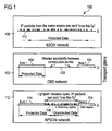
- APSON may be thought of as a hybrid network technology between Optical Burst Switching (OBS) and ASON (Automatic Switched Optical Networks). This will be appreciated from Figure 1 which shows the three transport networks 100 side-by-side.
- OBS Optical Burst Switching
- ASON Automatic Switched Optical Networks
- the bandwidth 104 associated to this path is reserved as long as the path is not torn down, which basically means that these bandwidth resources are not available to other sources. In other words, the transmitted data is protected as long as the path exists.
- ASON (108, Figure 1 ) data is sent as it arrives, i.e., "on-the-fly" through an established path.
- the data is normally IP packets 110 and the bandwidth is not reserved.
- QoS Quality of Service
- ASON is not structured and is more difficult to control than OBS.
- the duration of the reserved bandwidth 114 i.e., the duration of the protected data
- the APSON scheme is both a ⁇ -switching regime and an unprotected data time gap, wherein the bursts are transmitted under a protected transmission while the IP packets that are sent on-the-fly are transmitted, either protected or unprotected, in the ⁇ -switching. This allows for more flexibility when implementing different quality of service (QoS) to different customers based on, for example, customer plans.
- QoS quality of service
- APSON is really a unique network scheme.
- OBS optical link management
- Some other concepts were borrowed from OBS networks as well, such as the OBS bandwidth reservation scheme.
- APSON is distinctly different than OBS.
- APSON effectuates a circuit switching philosophy similar to ASON, whilst OBS networks use a packet switching approach.
- APSON while a hybrid of the two network philosophies, is a completely different type of network.
- APSON is a brand new switching scheme, it has not yet been discussed in the field how to provide a ring topology for APSON.
- rings are simple to implement and, for this reason, have historically played an important role in optical networks. For instance, routing, switching and network management tasks are considerably less complex in ring topologies in comparison to meshed topologies. For this reason, rings would be a highly desirable topology for deploying new optical network technologies such as APSON.
- the invention aims at providing the basic concepts for the deployment of a simple, yet, highly efficient APSON.
- special consideration is given to the current technological limitations at the optical layer, such, for example, the switching speed.
- the source in OBS networks sends a header packet and, after waiting an offset time, sends the burst as well.
- the source sends a header packet but it waits for an acknowledgement from the network before sending the burst.
- WR-OBS networks are the most promising architecture for optical ring networks
- APSON uses a similar acknowledgement-based variant of OBS signalling in order to setup a lightpath.
- OBS acknowledgement-based variant of OBS signalling
- an APSON ring topology would be able to reuse the standardized ASON control plane. Moreover, an APSON ring would be easier and quicker to deploy due to fewer technological challenges. An APSON ring would also offer less delay, higher throughput, lower signalling overhead and self-organizing architecture.
- APSON-based rings present advantages also in comparison to ⁇ -switching approaches.
- the present invention provides a feasible centralized APSON ring with present-day optical components without sacrificing high network performance and a corresponding method for data transmission.
- the concept is to design a distributed APSON ring that is feasible with present day optical components without renouncing to high network performance.
- APSON in the present invention reduces to zero, or substantially zero, or otherwise reducing, the number of switching actions per unit of time inside the ring network.
- a problem is solved by a method for transmitting data in a burst switching ring network with a plurality of nodes and distributed management with the features: the data is transmitted by the nodes as bursts or data packets containing protected data during a reserved time for which bandwidth has been reserved, and data packets containing unprotected data after the reserved time, a source node sending a path setup message, to request a data transmission between said source node and a destination node through intermediate nodes for connecting the source node and the destination node, determining by each intermediate node that a connection to a next node along the path is available, sending back a positive acknowledgement by the destination node if the path is available, and determining that the path is available for new data transmission when ongoing data transmission on the path is unprotected, stopping a current data transmission of data packets containing unprotected data on the path when the path or channel respectively is determined to be available for new data transmission.
- a burst switching ring network with a plurality of nodes and distributed management transmitting data, comprising, one or more channels coupling the nodes for transmitting the data between a source node and a destination node,the nodes being designed for sending bursts or data packets containing protected data during a reserved time for which bandwidth has been reserved, and sending data packets containing unprotected data after the reserved time, the source node designed to request a data transmission to be set up to the destination node through intermediate nodes, the nodes designed for determining that a connection to a next node along the path is available, and for determining that the path is available when the data transmission on the path is unprotected, the destination node designed for determining that the path is available and sending back a positive acknowledgement if the path is available, and for stopping a current data transmission of data packets containing unprotected data on the path when the path or channel respectively is determined to be available for new data transmission.
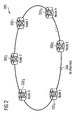
- a distributed ring architecture 200 will now be discussed with reference to Figure 2 .
- the distributed network of Figure 2 provides distributed or shared network control amongst the various nodes 202 1 - 202 N .
- the core node In order to schedule message flows the core node generates a path setup message indicating in a special field the length for which bandwidth will be reserved.
- the network or the central control node guarantees that if a positive acknowledgement to the path setup message is granted, no other node can interrupt the data transmission during this reserved time.
- Data transferred during the time for which bandwidth has been reserved is called protected data.
- Data transferred after the protected data has been sent is called unprotected data. No bandwidth has been reserved for unprotected data and therefore other sources can interrupt its transmission.
- a data flow comprises the transmission of the protected data plus possibly the transmission of unprotected data.
- a distributed ring architecture 200 with nodes 202 1 - 202 N in M channels 204. There are no core nodes.
- the present invention applies particularly to a type of network that transmits both bursts, i.e., data packets during reserved bandwidth, and data packets on-the-fly.
- the present invention pertains to the already-described APSON.
- N nodes 302 g - 302 k (Node g - Node k) are coupled to each other through M channels 304.
- a path setup message is forwarded by each of the intermediate nodes along the selected path.
- the intermediate node receiving the message determines whether the channel along the path that is to transmit data from the source node 302 i to the destination node 302 j is available to that particular intermediate node.
- the intermediate nodes that have access to the information of the connectivity of the channels coupled to them and it is the intermediate nodes that determine and decide that the path is available, i.e., unprotected.
- the intermediate node modifies the path setup message to indicate that the channel coupled to that intermediate is available and forwards the path setup message to the next intermediary node in the path. This process continues until the destination node 302 j receives the path setup message.
- the destination node 302 j only the destination node 302 j knows that the selected path is available. It is the destination node j 202 j , that receives the path setup message from the last intermediate node. At this time, the destination node 302 j then proceeds to set up the channel. Another way to describe the situation is that the path is not set up until the destination node 302 j receives the path setup message, because it is not until the last intermediary node forwards the path setup message to the destination node 302 j that the channel is available.
- APSON provides time multiplexing of the wavelength capacities normally, the number of channels will be below the number of nodes ( M ⁇ N ) in the present invention. This is a major advantage in comparison to ⁇ -switching networks. Without ⁇ -conversion an APSON data flow (composed by a burst plus possibly IP packets) uses the same wavelength along its path. Thus, minimizing the number of channels needed.
- an APSON data flow uses the same fixed combination of fibers along its path. This means at the logical layer (see figure 1 ) that the APSON data flow once in channel x does not switch to another channel y (with x ⁇ y ). If multimode fibers are being used, a channel represents a wavelength in one of these fibers. If monomode fibers are being used, a channel directly represents one of these fibers.
- node 302 i In order for node 302 i to send a data flow to node 302 j , the following steps are carried out. Preferably, the steps are carried out in the order set forth, but may be arranged in another order.
- each node 302 g - 302 k receives incoming IP packets, sorts them according to their destination and collects them in different buffers, each one for each destination.
- node 302 i sends a path setup message 306 to destination node 302 j .
- a predetermined algorithm such as an "aggregation strategy”
- the path setup message 306, in the preferred embodiment, includes a Source field, a Destination field, a Duration field and a Channel field.
- the Duration field indicates the duration of the protected data for which bandwidth will be reserved.
- the channel field indicates the channel on which the source wishes to send the data flow.
- the Source and Destination fields designate the source and destination nodes.
- each intermediate node along the path from source 302 i to destination node 302 j reads the path setup message 306 and checks for the availability of the channel specified in the channel field. If the channel is not available, the intermediate node sends a NACK (not acknowledge) message 308 back to the source node 302 i indicating that the data flow cannot be accommodated.
- NACK not acknowledge
- the intermediate node copies, in a special field of the NACK message 308 called the channel field, the number of the channel specified in the channel field of the path setup message 306.
- Each intermediate node receiving a NACK message 308 changes the status of the channel specified in the channel field to unavailable.
- the intermediate node forwards the path setup message 306 to the next node along the path of the data flow and changes the status of the channel specified in the channel field of the path setup message 306 to available.
- the path setup message 306 eventually arrives at the destination node.
- the destination node 302 j sends an ACK (acknowledge) message 210 back to the source node 302 i indicating that the data flow can be transferred.
- a fourth step when the source node 302 i receives a NACK message 308 it may perform one of the following operations according to the particular implementation of the decentralized APSON ring architecture. First, it may discard the data flow. For example, all of the packets may be discarded in the edge node buffer. Second, a data flow transmission may be reattempted after a certain time t attemp on a certain channel ⁇ . This time may be zero, constant, random or chosen according to a certain algorithm. The channel ⁇ may be the same as before or a different one chosen according to a certain algorithm.
- the source node 302 i receives an ACK message 210, it transfers the data flow.
- a fifth step when another source wishes to send a data flow on the same channel through partially or totally the same end-to-end path as the ongoing data flow transmission from node 302 i to 302 j , it sends a new path setup message to the destination node.
- the channel is determined to be available and the ongoing data flow is interrupted.
- the first is when a new source 302 k sends a new data flow through the source node 302 i of the ongoing data flow, as in Figure 3 .
- the second is when the source 302 i of the ongoing data flow sends the old data flow i->j through a new source 302 g of a new data flow 312 g->h (shown in FIG 3 ).
- node 302 i automatically stops sending the ongoing data flow when it receives the path setup from node 302 k .
- node 302 g sends a stop message 314 back to the source of the ongoing data flow (node i ).
- node 302 i receives a stop message 314 it automatically stops sending the ongoing data flow.
- the channel is determined to be unavailable and the ongoing data flow is not interrupted.
- the invention implements ⁇ -conversion-capable optical components.
- the path setup message is not provided with a channel field.
- each intermediate node checks if there is any available channel. This may be accomplished by providing a new parameter, L available that is designated the list of available channels for the transmission of the data flow in the intermediate node. If L available has more than one element, the intermediate node(s) selects one of the channels according to a certain criteria. The selected channel is declared as unavailable and the path setup message is forwarded. The remainder of the procedure is similar to the previously-described case.
- the path setup message includes an extra field called the Channel Pool field.
- the source node provides this field with the list of all possible channels through which it could send the data flow.
- Each intermediate node eliminates from this list the channels that are not available. However it declares as unavailable only the channel specified in the channel field of the path setup message similar to the above case.
- each intermediate node forwards the path setup message even if the channel specified in the channel field is not available.
- the intermediate node changes the value of the channel field to, for instance, -1, in order to inform the destination node that some intermediate nodes cannot accommodate the data flow in the specified channel. If the destination node receives a path setup message with the channel field intact, then it returns an ACK to the source signalling that it might begin the flow transmission.
- the destination node checks the channel pool field. If this field is not empty, then the destination node selects one channel from it according to a certain criteria and returns a NACK message to the source with an additional field, herein referred to as the Proposed Channel, containing the selected channel.
- Each intermediate node receiving a NACK message declares as available the channel specified in the channel field of the NACK message just as before.
- the source node receives the NACK message, reads the proposed channel field and returns another path setup with the proposed channel in the channel field with the hope that the proposed channel is still available. In this manner, the solution is more efficient since a NACK message might contain as well information regarding a channel which was at least available by the time the NACK message was created.
- the Distributed APSON Ring concept of the present invention is advantageous. For one thing, the solution is valid for both uni- and bidirectional links. Due to the efficient wavelength time multiplexing of APSON, the number of wavelengths for a given ring topology and given offered traffic volume is reduced in comparison to WR-OBS, OBS and especially to ⁇ -switching networks. Since each wavelength has associated several optical components, some of which are quite expensive such as the tuneable lasers, the number of wavelengths is reduced. This results in important cost savings on optical components that are no longer needed.
- the inventive distributed APSON rings offer a lower delay, delay jitter that their OBS-based counterparts. For the same reason, the blocking probability in distributed APSON rings is virtually zero.
- the concept allows for QoS implementations, as well as an all-optical transport plane. The concept allows to implement more complex and efficient or less complex and efficient solutions depending on the needs.
- a distributed APSON ring architecture presents no single point of failure (no centralized control node) unlike a centralized APSON ring approach.
- the present invention presents no scalability problems due to the increasing workload in a centralized control node as network increases its size unlike in a centralized APSON ring approach.
Landscapes
- Engineering & Computer Science (AREA)
- Computer Networks & Wireless Communication (AREA)
- Signal Processing (AREA)
- Small-Scale Networks (AREA)
Claims (14)
- Verfahren zum Übertragen von Daten in einem Burst-Switching-Ringnetz mit einer Vielzahl von Knoten (302g-302k) und verteiltem Management,
dadurch gekennzeichnet, daß
die Daten durch die Knoten (302g-302k) während einer reservierten Zeit, für die Bandbreite reserviert worden ist, als geschützte Daten enthaltende Bursts oder Datenpakete übertragen werden und nach der reservierten Zeit als ungeschützte Daten enthaltende Datenpakete,
ein Ursprungsknoten (302i) eine Pfadeinrichtungsnachricht (306) zur Anforderung einer Datenübertragung zwischen dem Ursprungsknoten (302i) und einem Zielknoten (302j) durch Zwischenknoten (302g, 302h) zum Verbinden des Ursprungsknotens (302i) und des Zielknotens (302j) sendet,
Bestimmen durch jeden Zwischenknoten (302g, 302h), das eine Verbindung zu einem nächsten Knoten (302h, 302j) entlang dem Pfad verfügbar ist,
Zurücksenden einer positiven Bestätigung (ACK) durch den Zielknoten (302j), wenn der Pfad verfügbar ist, und
Bestimmen, daß der Pfad für eine neue Datenübertragung (g->h) verfügbar ist, wenn bestehende Datenübertragung (i->j) auf dem Pfad ungeschützt ist,
Anhalten einer gegenwärtigen Datenübertragung (i->j) von ungeschützte Daten enthaltenden Datenpaketen auf dem Pfad, wenn bestimmt wird, daß der Pfad bzw. Kanal für neue Datenübertragung (g->h) verfügbar ist. - Verfahren nach Anspruch 1, weiterhin gekennzeichnet durch den Schritt des Sendens einer Haltnachricht (314) durch einen zu einem neuen Ursprungsknoten (302g) werdenden Knoten an einen ungeschützte Daten sendenden Ursprungsknoten (302i).
- Verfahren nach Anspruch 1 oder 2, weiterhin dadurch gekennzeichnet, daß, wenn der Pfad nicht verfügbar ist, der Zwischenknoten (302g, 302h) eine Nichtbestätigungsnachricht (NACK, 308) an den Ursprungsknoten (302i) sendet, die anzeigt, daß die Datenübertragung nicht aufgenommen werden kann.
- Verfahren nach Anspruch 3, weiterhin dadurch gekennzeichnet, daß, wenn der Ursprungsknoten (302i) eine Nichtbestätigungsnachricht (NACK) (308) empfängt, der Datenfluß vom Ursprungsknoten (302i) verworfen wird.
- Verfahren nach einem der vorhergehenden Ansprüche, weiterhin dadurch gekennzeichnet, daß wenn die Pfadeinrichtungsnachricht (306) am Zielknoten (302j) ankommt, der Zielknoten (302j) eine Bestätigungsnachricht (ACK, 310) zum Ursprungsknoten (302i) sendet, die anzeigt, daß der Datenfluß auf einem bestimmten Pfad übermittelt werden kann.
- Verfahren nach einem der vorhergehenden Ansprüche 1-5, weiterhin dadurch gekennzeichnet, daß die Datenübertragung (i->j) nach einer gewissen Zeit (tattemp) auf einem gewissen Kanal (λ) wieder versucht wird.
- Verfahren nach einem der vorhergehenden Ansprüche, weiterhin dadurch gekennzeichnet, daß, wenn ein anderer Ursprungsknoten (302g) eine Datenübertragung über mindestens teilweise den gleichen Pfad (302g-302h) zu senden wünscht, der andere Ursprungsknoten (302g) eine neue Pfadeinrichtungsnachricht zu seinem Zielknoten (302h) sendet.
- Verfahren nach einem der vorhergehenden Ansprüche, weiterhin dadurch gekennzeichnet, daß die Pfadeinrichtungsnachricht (312) ein Kanal-Pool-Feld enthält und der Ursprungsknoten (302i) in dem Kanal-Pool-Feld eine Liste aller möglichen Kanäle einträgt, über die der Ursprungsknoten (302i) die Datenübertragung sendet.
- Burst-Switching-Ringnetz mit einer Vielzahl von Knoten (302g-302k) und datenübertragendem verteiltem Management, mit folgendem:einem oder mehreren die Knoten (302g-302k) verkoppelnden Kanälen zum Übertragen der Daten zwischen einem Ursprungsknoten (302i) und einem Zielknoten (302j),wobei die Knoten (302g-302k) zum Senden von geschützte Daten enthaltenden Bursts oder Datenpaketen während einer reservierten Zeit, für die Bandbreite reserviert worden ist, und zum Senden von ungeschützte Daten enthaltenden Datenpaketen nach der reservierten Zeit ausgelegt sind,wobei der Ursprungsknoten (302i) zum Anfordern einer zum Zielknoten (302j) durch Zwischenknoten (302g, 302h) aufzubauenden Datenübertragung ausgelegt ist,wobei die Knoten (302g, 302h) zum Bestimmen, daß eine Verbindung zu einem nächsten Knoten (302h, 302j) entlang dem Pfad verfügbar ist, undzum Bestimmen, daß der Pfad verfügbar ist, wenn die Datenübertragung (i->j) auf dem Pfad ungeschützt ist, ausgelegt sind,der Zielknoten (302j) zum Bestimmen, daß der Pfad verfügbar ist und Zurücksenden einer positiven Bestätigung (ACK), wenn der Pfad verfügbar ist, ausgelegt ist, und zum Anhalten einer gegenwärtigen Datenübertragung (i->j) von ungeschützte Daten enthaltenden Datenpaketen auf dem Pfad, wenn bestimmt wird, daß der Pfad bzw. Kanal für neue Datenübertragung (g->h) verfügbar ist.
- Ringnetz nach Anspruch 9, gekennzeichnet dadurch, daß der Ursprungsknoten (302i) zum Senden einer Pfadeinrichtungsnachricht (306) ausgelegt ist, die einen Pfad zum Einrichten einer Datenübertragung zum Zielknoten (302j) anzeigt.
- Ringnetz nach Anspruch 10, dadurch gekennzeichnet, daß jeder Zwischenknoten auf dem Pfad zwischen dem Ursprungsknoten (302i) und dem Zielknoten (302j) zum Auslesen des Pfads aus der Pfadeinrichtungsnachricht (306) ausgelegt ist.
- Ringnetz nach Anspruch 10 oder 11, dadurch gekennzeichnet, daß jeder Zwischenknoten auf dem Pfad zwischen dem Ursprungsknoten (302i) und dem Zielknoten (302j) zum Bestimmen einer Verfügbarkeit eines mit dem jeweiligen Zwischenknoten und einem nächsten Knoten auf dem in der Pfadeinrichtungsnachricht (306) angegebenen Pfad verbundenen Kanals ausgelegt ist.
- Ringnetz nach Anspruch 12, weiterhin dadurch gekennzeichnet, daß jeder Zwischenknoten (302g-302h) zum Setzen eines Zustandes des mit dem jeweiligen Zwischenknoten verbundenen Kanals in der Pfadeinrichtungsnachricht ausgelegt ist.
- Ringnetz nach einem der vorhergehenden Ansprüche 9-13, weiterhin dadurch gekennzeichnet, daß das verteilte Ringnetz λ-umwandlungsfähige optische Bauelemente implementiert.
Priority Applications (4)
| Application Number | Priority Date | Filing Date | Title |
|---|---|---|---|
| EP04026929A EP1657952B1 (de) | 2004-11-12 | 2004-11-12 | Ein Ringnetz für ein Burst-geschaltetes Netz mit verteiltem Management |
| DE602004014784T DE602004014784D1 (de) | 2004-11-12 | 2004-11-12 | Ein Ringnetz für ein Burst-geschaltetes Netz mit verteiltem Management |
| AT04026929T ATE400157T1 (de) | 2004-11-12 | 2004-11-12 | Ein ringnetz für ein burst-geschaltetes netz mit verteiltem management |
| US11/272,171 US20060104296A1 (en) | 2004-11-12 | 2005-11-10 | Ring network for a burst switching network with distributed management |
Applications Claiming Priority (1)
| Application Number | Priority Date | Filing Date | Title |
|---|---|---|---|
| EP04026929A EP1657952B1 (de) | 2004-11-12 | 2004-11-12 | Ein Ringnetz für ein Burst-geschaltetes Netz mit verteiltem Management |
Publications (2)
| Publication Number | Publication Date |
|---|---|
| EP1657952A1 EP1657952A1 (de) | 2006-05-17 |
| EP1657952B1 true EP1657952B1 (de) | 2008-07-02 |
Family
ID=34927366
Family Applications (1)
| Application Number | Title | Priority Date | Filing Date |
|---|---|---|---|
| EP04026929A Expired - Lifetime EP1657952B1 (de) | 2004-11-12 | 2004-11-12 | Ein Ringnetz für ein Burst-geschaltetes Netz mit verteiltem Management |
Country Status (4)
| Country | Link |
|---|---|
| US (1) | US20060104296A1 (de) |
| EP (1) | EP1657952B1 (de) |
| AT (1) | ATE400157T1 (de) |
| DE (1) | DE602004014784D1 (de) |
Families Citing this family (12)
| Publication number | Priority date | Publication date | Assignee | Title |
|---|---|---|---|---|
| US7660927B2 (en) * | 2007-05-21 | 2010-02-09 | International Business Machines Corporation | Apparatus and method to control access to stored information |
| CN101741631B (zh) * | 2008-11-17 | 2012-08-29 | 华为技术有限公司 | 一种告警和性能监测方法及网络节点 |
| CN102045186B (zh) * | 2009-10-19 | 2013-07-17 | 中国移动通信集团公司 | 一种事件分析方法及系统 |
| US8774207B2 (en) * | 2010-07-31 | 2014-07-08 | Motorola Solutions, Inc. | Methods for bearer reservation, maintenance, and use in a communication system |
| US8838156B2 (en) | 2010-10-22 | 2014-09-16 | Motorola Solutions, Inc. | Multi-bearer rate control for transporting user plane data |
| US9693264B2 (en) * | 2011-04-18 | 2017-06-27 | Lg Electronics Inc. | Signal transmission method and device in a wireless communication system |
| US9553801B2 (en) * | 2012-09-25 | 2017-01-24 | Google Inc. | Network device |
| EP2843967B1 (de) * | 2013-08-28 | 2017-05-24 | Alcatel Lucent | Verfahren zur Planung von Daten durch ein optisches Burst-Vermittlungsnetzwerk |
| CN117880991B (zh) * | 2019-05-20 | 2025-02-18 | 华为技术有限公司 | 资源分配的指示方法及装置 |
| US12405826B2 (en) * | 2021-08-30 | 2025-09-02 | International Business Machines Corporation | Reservation mechanism for nodes with phase constraints |
| US11580058B1 (en) | 2021-08-30 | 2023-02-14 | International Business Machines Corporation | Hierarchical ring-based interconnection network for symmetric multiprocessors |
| US12265850B2 (en) | 2021-08-30 | 2025-04-01 | International Business Machines Corporation | Reservation mechanism for node with token constraints for preventing node starvation in a circular topology network |
Family Cites Families (7)
| Publication number | Priority date | Publication date | Assignee | Title |
|---|---|---|---|---|
| US6671256B1 (en) * | 2000-02-03 | 2003-12-30 | Alcatel | Data channel reservation in optical burst-switched networks |
| US7054557B1 (en) * | 2000-10-11 | 2006-05-30 | Nortel Networks Limited | Technique for routing data within an optical network |
| US20020059408A1 (en) * | 2000-11-02 | 2002-05-16 | Krishna Pattabhiraman | Dynamic traffic management on a shared medium |
| US7039316B2 (en) * | 2001-01-30 | 2006-05-02 | The Regents Of The University Of California | Optical layer multicasting using a multiple sub-carrier header and a multicast switch with active header insertion via reflective single sideband optical processing |
| CA2410143C (en) * | 2001-11-02 | 2010-02-02 | Nippon Telegraph And Telephone Corporation | Optical dynamic burst switch |
| US20030206521A1 (en) * | 2002-05-06 | 2003-11-06 | Chunming Qiao | Methods to route and re-route data in OBS/LOBS and other burst swithched networks |
| KR100474694B1 (ko) * | 2002-10-12 | 2005-03-10 | 삼성전자주식회사 | 버스트 데이터 통신을 위한 링형 광네트워크 |
-
2004
- 2004-11-12 EP EP04026929A patent/EP1657952B1/de not_active Expired - Lifetime
- 2004-11-12 AT AT04026929T patent/ATE400157T1/de not_active IP Right Cessation
- 2004-11-12 DE DE602004014784T patent/DE602004014784D1/de not_active Expired - Lifetime
-
2005
- 2005-11-10 US US11/272,171 patent/US20060104296A1/en not_active Abandoned
Also Published As
| Publication number | Publication date |
|---|---|
| US20060104296A1 (en) | 2006-05-18 |
| ATE400157T1 (de) | 2008-07-15 |
| EP1657952A1 (de) | 2006-05-17 |
| DE602004014784D1 (de) | 2008-08-14 |
Similar Documents
| Publication | Publication Date | Title |
|---|---|---|
| KR100798018B1 (ko) | 광 경로의 비정밀 예약 설립 방법, 스위칭 장치 및 머신판독가능 매체 | |
| US7848651B2 (en) | Selective distribution messaging scheme for an optical network | |
| US7031607B1 (en) | MPLS application to optical cross-connect using wavelength as a label | |
| US7596313B1 (en) | Method and apparatus for processing protection switching mechanism in optical channel shared protection rings | |
| US6879783B1 (en) | Node device and optical network system | |
| Sengupta et al. | From network design to dynamic provisioning and restoration in optical cross-connect mesh networks: An architectural and algorithmic overview | |
| US8660427B2 (en) | Method and apparatus of the architecture and operation of control processing unit in wavelenght-division-multiplexed photonic burst-switched networks | |
| JP4853037B2 (ja) | 光ネットワークシステム、ハブ・ノード | |
| US7428383B2 (en) | Architecture, method and system of WDM-based photonic burst switched networks | |
| EP1657952B1 (de) | Ein Ringnetz für ein Burst-geschaltetes Netz mit verteiltem Management | |
| WO2004062313A1 (en) | Method and apparatus for data and control packet scheduling in wdm photonic burst-switched networks | |
| US20100284269A1 (en) | Multi-Node State Recovery for a Communication Network | |
| EP1439730B1 (de) | Überlastkontrolle in einem optischen Netzwerk mit Burstschaltung | |
| US20070159964A1 (en) | Protection path reservation method and node unit | |
| US7269346B1 (en) | Optical automatic protection switching mechanism for optical channel shared protection rings | |
| US7826747B2 (en) | Optical burst transport using an electro-optic switch | |
| US7539128B2 (en) | Method for protecting and restoring link using optical label merging and dynamic resource sharing with network load | |
| Assi et al. | Control and management protocols for survivable optical mesh networks | |
| Maier et al. | Protectoration: a fast and efficient multiple-failure recovery technique for resilient packet ring using dark fiber | |
| EP1655987B1 (de) | Ein Ringnetz für ein Burst-geschaltetes Netz mit zentralem Management | |
| US8634430B2 (en) | Multicast transmissions in optical burst transport | |
| Salvador et al. | An all-optical WDM packet-switched network architecture with support for group communication | |
| US7412168B2 (en) | MPLS application to optical cross-connect using wavelength as a label | |
| US20100284268A1 (en) | Node State Recovery for a Communication Network | |
| JP3777261B2 (ja) | 光ネットワーク |
Legal Events
| Date | Code | Title | Description |
|---|---|---|---|
| PUAI | Public reference made under article 153(3) epc to a published international application that has entered the european phase |
Free format text: ORIGINAL CODE: 0009012 |
|
| AK | Designated contracting states |
Kind code of ref document: A1 Designated state(s): AT BE BG CH CY CZ DE DK EE ES FI FR GB GR HU IE IS IT LI LU MC NL PL PT RO SE SI SK TR |
|
| AX | Request for extension of the european patent |
Extension state: AL HR LT LV MK YU |
|
| 17P | Request for examination filed |
Effective date: 20061117 |
|
| AKX | Designation fees paid |
Designated state(s): AT BE BG CH CY CZ DE DK EE ES FI FR GB GR HU IE IS IT LI LU MC NL PL PT RO SE SI SK TR |
|
| 17Q | First examination report despatched |
Effective date: 20070719 |
|
| RAP1 | Party data changed (applicant data changed or rights of an application transferred) |
Owner name: NOKIA SIEMENS NETWORKS GMBH & CO. KG |
|
| RAP3 | Party data changed (applicant data changed or rights of an application transferred) |
Owner name: NOKIA SIEMENS NETWORKS S.P.A. |
|
| RAP3 | Party data changed (applicant data changed or rights of an application transferred) |
Owner name: NOKIA SIEMENS NETWORKS GMBH & CO. KG |
|
| GRAP | Despatch of communication of intention to grant a patent |
Free format text: ORIGINAL CODE: EPIDOSNIGR1 |
|
| GRAC | Information related to communication of intention to grant a patent modified |
Free format text: ORIGINAL CODE: EPIDOSCIGR1 |
|
| GRAS | Grant fee paid |
Free format text: ORIGINAL CODE: EPIDOSNIGR3 |
|
| GRAA | (expected) grant |
Free format text: ORIGINAL CODE: 0009210 |
|
| AK | Designated contracting states |
Kind code of ref document: B1 Designated state(s): AT BE BG CH CY CZ DE DK EE ES FI FR GB GR HU IE IS IT LI LU MC NL PL PT RO SE SI SK TR |
|
| REG | Reference to a national code |
Ref country code: GB Ref legal event code: FG4D |
|
| REG | Reference to a national code |
Ref country code: CH Ref legal event code: EP |
|
| REF | Corresponds to: |
Ref document number: 602004014784 Country of ref document: DE Date of ref document: 20080814 Kind code of ref document: P |
|
| REG | Reference to a national code |
Ref country code: IE Ref legal event code: FG4D |
|
| PG25 | Lapsed in a contracting state [announced via postgrant information from national office to epo] |
Ref country code: SI Free format text: LAPSE BECAUSE OF FAILURE TO SUBMIT A TRANSLATION OF THE DESCRIPTION OR TO PAY THE FEE WITHIN THE PRESCRIBED TIME-LIMIT Effective date: 20080702 |
|
| PG25 | Lapsed in a contracting state [announced via postgrant information from national office to epo] |
Ref country code: NL Free format text: LAPSE BECAUSE OF FAILURE TO SUBMIT A TRANSLATION OF THE DESCRIPTION OR TO PAY THE FEE WITHIN THE PRESCRIBED TIME-LIMIT Effective date: 20080702 |
|
| NLV1 | Nl: lapsed or annulled due to failure to fulfill the requirements of art. 29p and 29m of the patents act | ||
| PG25 | Lapsed in a contracting state [announced via postgrant information from national office to epo] |
Ref country code: PT Free format text: LAPSE BECAUSE OF FAILURE TO SUBMIT A TRANSLATION OF THE DESCRIPTION OR TO PAY THE FEE WITHIN THE PRESCRIBED TIME-LIMIT Effective date: 20081202 Ref country code: IS Free format text: LAPSE BECAUSE OF FAILURE TO SUBMIT A TRANSLATION OF THE DESCRIPTION OR TO PAY THE FEE WITHIN THE PRESCRIBED TIME-LIMIT Effective date: 20081102 Ref country code: ES Free format text: LAPSE BECAUSE OF FAILURE TO SUBMIT A TRANSLATION OF THE DESCRIPTION OR TO PAY THE FEE WITHIN THE PRESCRIBED TIME-LIMIT Effective date: 20081013 |
|
| PG25 | Lapsed in a contracting state [announced via postgrant information from national office to epo] |
Ref country code: BG Free format text: LAPSE BECAUSE OF FAILURE TO SUBMIT A TRANSLATION OF THE DESCRIPTION OR TO PAY THE FEE WITHIN THE PRESCRIBED TIME-LIMIT Effective date: 20081002 Ref country code: AT Free format text: LAPSE BECAUSE OF FAILURE TO SUBMIT A TRANSLATION OF THE DESCRIPTION OR TO PAY THE FEE WITHIN THE PRESCRIBED TIME-LIMIT Effective date: 20080702 Ref country code: FI Free format text: LAPSE BECAUSE OF FAILURE TO SUBMIT A TRANSLATION OF THE DESCRIPTION OR TO PAY THE FEE WITHIN THE PRESCRIBED TIME-LIMIT Effective date: 20080702 |
|
| PG25 | Lapsed in a contracting state [announced via postgrant information from national office to epo] |
Ref country code: BE Free format text: LAPSE BECAUSE OF FAILURE TO SUBMIT A TRANSLATION OF THE DESCRIPTION OR TO PAY THE FEE WITHIN THE PRESCRIBED TIME-LIMIT Effective date: 20080702 |
|
| PG25 | Lapsed in a contracting state [announced via postgrant information from national office to epo] |
Ref country code: DK Free format text: LAPSE BECAUSE OF FAILURE TO SUBMIT A TRANSLATION OF THE DESCRIPTION OR TO PAY THE FEE WITHIN THE PRESCRIBED TIME-LIMIT Effective date: 20080702 Ref country code: EE Free format text: LAPSE BECAUSE OF FAILURE TO SUBMIT A TRANSLATION OF THE DESCRIPTION OR TO PAY THE FEE WITHIN THE PRESCRIBED TIME-LIMIT Effective date: 20080702 |
|
| PLBE | No opposition filed within time limit |
Free format text: ORIGINAL CODE: 0009261 |
|
| STAA | Information on the status of an ep patent application or granted ep patent |
Free format text: STATUS: NO OPPOSITION FILED WITHIN TIME LIMIT |
|
| PG25 | Lapsed in a contracting state [announced via postgrant information from national office to epo] |
Ref country code: SK Free format text: LAPSE BECAUSE OF FAILURE TO SUBMIT A TRANSLATION OF THE DESCRIPTION OR TO PAY THE FEE WITHIN THE PRESCRIBED TIME-LIMIT Effective date: 20080702 Ref country code: RO Free format text: LAPSE BECAUSE OF FAILURE TO SUBMIT A TRANSLATION OF THE DESCRIPTION OR TO PAY THE FEE WITHIN THE PRESCRIBED TIME-LIMIT Effective date: 20080702 Ref country code: CZ Free format text: LAPSE BECAUSE OF FAILURE TO SUBMIT A TRANSLATION OF THE DESCRIPTION OR TO PAY THE FEE WITHIN THE PRESCRIBED TIME-LIMIT Effective date: 20080702 |
|
| 26N | No opposition filed |
Effective date: 20090403 |
|
| PG25 | Lapsed in a contracting state [announced via postgrant information from national office to epo] |
Ref country code: MC Free format text: LAPSE BECAUSE OF NON-PAYMENT OF DUE FEES Effective date: 20081130 |
|
| REG | Reference to a national code |
Ref country code: CH Ref legal event code: PL |
|
| PG25 | Lapsed in a contracting state [announced via postgrant information from national office to epo] |
Ref country code: CH Free format text: LAPSE BECAUSE OF NON-PAYMENT OF DUE FEES Effective date: 20081130 Ref country code: LI Free format text: LAPSE BECAUSE OF NON-PAYMENT OF DUE FEES Effective date: 20081130 Ref country code: IE Free format text: LAPSE BECAUSE OF NON-PAYMENT OF DUE FEES Effective date: 20081112 |
|
| PG25 | Lapsed in a contracting state [announced via postgrant information from national office to epo] |
Ref country code: SE Free format text: LAPSE BECAUSE OF FAILURE TO SUBMIT A TRANSLATION OF THE DESCRIPTION OR TO PAY THE FEE WITHIN THE PRESCRIBED TIME-LIMIT Effective date: 20081002 |
|
| PG25 | Lapsed in a contracting state [announced via postgrant information from national office to epo] |
Ref country code: PL Free format text: LAPSE BECAUSE OF FAILURE TO SUBMIT A TRANSLATION OF THE DESCRIPTION OR TO PAY THE FEE WITHIN THE PRESCRIBED TIME-LIMIT Effective date: 20080702 |
|
| PG25 | Lapsed in a contracting state [announced via postgrant information from national office to epo] |
Ref country code: HU Free format text: LAPSE BECAUSE OF FAILURE TO SUBMIT A TRANSLATION OF THE DESCRIPTION OR TO PAY THE FEE WITHIN THE PRESCRIBED TIME-LIMIT Effective date: 20090103 Ref country code: LU Free format text: LAPSE BECAUSE OF NON-PAYMENT OF DUE FEES Effective date: 20081112 Ref country code: CY Free format text: LAPSE BECAUSE OF FAILURE TO SUBMIT A TRANSLATION OF THE DESCRIPTION OR TO PAY THE FEE WITHIN THE PRESCRIBED TIME-LIMIT Effective date: 20080702 |
|
| PG25 | Lapsed in a contracting state [announced via postgrant information from national office to epo] |
Ref country code: TR Free format text: LAPSE BECAUSE OF FAILURE TO SUBMIT A TRANSLATION OF THE DESCRIPTION OR TO PAY THE FEE WITHIN THE PRESCRIBED TIME-LIMIT Effective date: 20080702 |
|
| PG25 | Lapsed in a contracting state [announced via postgrant information from national office to epo] |
Ref country code: GR Free format text: LAPSE BECAUSE OF FAILURE TO SUBMIT A TRANSLATION OF THE DESCRIPTION OR TO PAY THE FEE WITHIN THE PRESCRIBED TIME-LIMIT Effective date: 20081003 |
|
| REG | Reference to a national code |
Ref country code: DE Ref legal event code: R082 Ref document number: 602004014784 Country of ref document: DE Representative=s name: BOEHMERT & BOEHMERT, DE |
|
| REG | Reference to a national code |
Ref country code: DE Ref legal event code: R081 Ref document number: 602004014784 Country of ref document: DE Owner name: XIEON NETWORKS S.A.R.L., LU Free format text: FORMER OWNER: NOKIA SIEMENS NETWORKS GMBH & CO. KG, 81541 MUENCHEN, DE Effective date: 20131106 Ref country code: DE Ref legal event code: R082 Ref document number: 602004014784 Country of ref document: DE Representative=s name: BOEHMERT & BOEHMERT, DE Effective date: 20131106 Ref country code: DE Ref legal event code: R082 Ref document number: 602004014784 Country of ref document: DE Representative=s name: BOEHMERT & BOEHMERT ANWALTSPARTNERSCHAFT MBB -, DE Effective date: 20131106 |
|
| REG | Reference to a national code |
Ref country code: GB Ref legal event code: 732E Free format text: REGISTERED BETWEEN 20131212 AND 20131218 |
|
| REG | Reference to a national code |
Ref country code: GB Ref legal event code: 732E Free format text: REGISTERED BETWEEN 20140130 AND 20140205 |
|
| REG | Reference to a national code |
Ref country code: FR Ref legal event code: GC Effective date: 20140408 Ref country code: FR Ref legal event code: TP Owner name: XIEON NETWORKS S.A.R.L., LU Effective date: 20140408 |
|
| REG | Reference to a national code |
Ref country code: FR Ref legal event code: GC Effective date: 20150922 |
|
| REG | Reference to a national code |
Ref country code: FR Ref legal event code: PLFP Year of fee payment: 12 |
|
| PGFP | Annual fee paid to national office [announced via postgrant information from national office to epo] |
Ref country code: IT Payment date: 20151125 Year of fee payment: 12 Ref country code: GB Payment date: 20151118 Year of fee payment: 12 Ref country code: DE Payment date: 20151119 Year of fee payment: 12 |
|
| PGFP | Annual fee paid to national office [announced via postgrant information from national office to epo] |
Ref country code: FR Payment date: 20151119 Year of fee payment: 12 |
|
| REG | Reference to a national code |
Ref country code: DE Ref legal event code: R119 Ref document number: 602004014784 Country of ref document: DE |
|
| GBPC | Gb: european patent ceased through non-payment of renewal fee |
Effective date: 20161112 |
|
| REG | Reference to a national code |
Ref country code: FR Ref legal event code: ST Effective date: 20170731 |
|
| PG25 | Lapsed in a contracting state [announced via postgrant information from national office to epo] |
Ref country code: IT Free format text: LAPSE BECAUSE OF NON-PAYMENT OF DUE FEES Effective date: 20161112 Ref country code: FR Free format text: LAPSE BECAUSE OF NON-PAYMENT OF DUE FEES Effective date: 20161130 |
|
| PG25 | Lapsed in a contracting state [announced via postgrant information from national office to epo] |
Ref country code: DE Free format text: LAPSE BECAUSE OF NON-PAYMENT OF DUE FEES Effective date: 20170601 Ref country code: GB Free format text: LAPSE BECAUSE OF NON-PAYMENT OF DUE FEES Effective date: 20161112 |