EP1657811A2 - Apparatus for controlling speed of fan motor of air-conditioner having an induction rotor and a permanent maget rotor - Google Patents
Apparatus for controlling speed of fan motor of air-conditioner having an induction rotor and a permanent maget rotor Download PDFInfo
- Publication number
- EP1657811A2 EP1657811A2 EP05005807A EP05005807A EP1657811A2 EP 1657811 A2 EP1657811 A2 EP 1657811A2 EP 05005807 A EP05005807 A EP 05005807A EP 05005807 A EP05005807 A EP 05005807A EP 1657811 A2 EP1657811 A2 EP 1657811A2
- Authority
- EP
- European Patent Office
- Prior art keywords
- fan motor
- triac
- duty ratio
- rpm
- control signal
- Prior art date
- Legal status (The legal status is an assumption and is not a legal conclusion. Google has not performed a legal analysis and makes no representation as to the accuracy of the status listed.)
- Granted
Links
Images


Classifications
-
- H—ELECTRICITY
- H02—GENERATION; CONVERSION OR DISTRIBUTION OF ELECTRIC POWER
- H02P—CONTROL OR REGULATION OF ELECTRIC MOTORS, ELECTRIC GENERATORS OR DYNAMO-ELECTRIC CONVERTERS; CONTROLLING TRANSFORMERS, REACTORS OR CHOKE COILS
- H02P27/00—Arrangements or methods for the control of AC motors characterised by the kind of supply voltage
- H02P27/04—Arrangements or methods for the control of AC motors characterised by the kind of supply voltage using variable-frequency supply voltage, e.g. inverter or converter supply voltage
- H02P27/16—Arrangements or methods for the control of AC motors characterised by the kind of supply voltage using variable-frequency supply voltage, e.g. inverter or converter supply voltage using AC to AC converters without intermediate conversion to DC
-
- H—ELECTRICITY
- H02—GENERATION; CONVERSION OR DISTRIBUTION OF ELECTRIC POWER
- H02K—DYNAMO-ELECTRIC MACHINES
- H02K16/00—Machines with more than one rotor or stator
- H02K16/02—Machines with one stator and two or more rotors
-
- H—ELECTRICITY
- H02—GENERATION; CONVERSION OR DISTRIBUTION OF ELECTRIC POWER
- H02K—DYNAMO-ELECTRIC MACHINES
- H02K17/00—Asynchronous induction motors; Asynchronous induction generators
- H02K17/02—Asynchronous induction motors
- H02K17/26—Asynchronous induction motors having rotors or stators designed to permit synchronous operation
-
- H—ELECTRICITY
- H02—GENERATION; CONVERSION OR DISTRIBUTION OF ELECTRIC POWER
- H02P—CONTROL OR REGULATION OF ELECTRIC MOTORS, ELECTRIC GENERATORS OR DYNAMO-ELECTRIC CONVERTERS; CONTROLLING TRANSFORMERS, REACTORS OR CHOKE COILS
- H02P25/00—Arrangements or methods for the control of AC motors characterised by the kind of AC motor or by structural details
-
- F—MECHANICAL ENGINEERING; LIGHTING; HEATING; WEAPONS; BLASTING
- F24—HEATING; RANGES; VENTILATING
- F24F—AIR-CONDITIONING; AIR-HUMIDIFICATION; VENTILATION; USE OF AIR CURRENTS FOR SCREENING
- F24F11/00—Control or safety arrangements
- F24F11/70—Control systems characterised by their outputs; Constructional details thereof
- F24F11/72—Control systems characterised by their outputs; Constructional details thereof for controlling the supply of treated air, e.g. its pressure
- F24F11/74—Control systems characterised by their outputs; Constructional details thereof for controlling the supply of treated air, e.g. its pressure for controlling air flow rate or air velocity
- F24F11/77—Control systems characterised by their outputs; Constructional details thereof for controlling the supply of treated air, e.g. its pressure for controlling air flow rate or air velocity by controlling the speed of ventilators
-
- Y—GENERAL TAGGING OF NEW TECHNOLOGICAL DEVELOPMENTS; GENERAL TAGGING OF CROSS-SECTIONAL TECHNOLOGIES SPANNING OVER SEVERAL SECTIONS OF THE IPC; TECHNICAL SUBJECTS COVERED BY FORMER USPC CROSS-REFERENCE ART COLLECTIONS [XRACs] AND DIGESTS
- Y02—TECHNOLOGIES OR APPLICATIONS FOR MITIGATION OR ADAPTATION AGAINST CLIMATE CHANGE
- Y02B—CLIMATE CHANGE MITIGATION TECHNOLOGIES RELATED TO BUILDINGS, e.g. HOUSING, HOUSE APPLIANCES OR RELATED END-USER APPLICATIONS
- Y02B30/00—Energy efficient heating, ventilation or air conditioning [HVAC]
- Y02B30/70—Efficient control or regulation technologies, e.g. for control of refrigerant flow, motor or heating
Definitions
- the present invention relates to an air-conditioner and, more particularly, to an apparatus for controlling a speed of a fan motor of an air-conditioner.
- a single-phase induction motor is used as a fan motor of an air-conditioner.
- the single-phase induction motor supplies a magnetizing current generating a rotating field and an induced current generated from a rotor to windings connected with an external power terminal.
- the single-phase induction motor has a limitation in enhancing efficiency due to a primary copper loss of a stator and a secondary copper loss of the rotor.
- HIM Hybrid Induction Motor
- Figure 1 is a schematic sectional view of the HIM in accordance with a conventional art
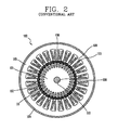
- Figure 2 is a schematic sectional top view taken along line B-B' of the HIM of Figure 1.
- a bracket 104 of the conventional HIM 100 includes a stator 105 and an induction rotor 101 installed at an inner side of the stator 105.
- a plurality of slots 108 are protrusively formed at an inner side of the stator 105 and coils 103 for applying a current are wound at the slots 108.
- Aluminum rotor bars 112 are vertically inserted into a plurality of air gaps formed in an up/down direction at an edge of the rotor 101, and the aluminum rotor bars 112 are connected by an end ring 102.
- a rotating shaft 109 for transferring a rotational force of the rotor 101 to outside is installed in an air gap 110 formed at the center of the induction rotor 101.
- the rotating shaft 109 can be rotated by an oilless bearing 107 installed at the bracket 104.
- a permanent magnet rotor 106 for rotating the rotor 101 with a strong magnetic flux while being rotated by rotating field generated from the stator 105 is installed between the stator 105 and the induction rotor 101.
- the permanent magnet rotor 106 When an AC voltage is applied to the conventional HIM, the permanent magnet rotor 106 is rotated by the current applied to the coil 103 of the stator 105, and the rotating permanent magnet rotor 106 generates a rotating field with strong magnetic flux, to rotate the induction rotator 101. At this time, the permanent magnet rotor 106 in a low inertia state is separated from a fan (not shown) and rotated owing to the rotating field of the stator 105, and as a torque generating magnetic flux is supplied to the induction rotor 101 owing to the rotating field of the permanent magnet rotor 10, the induction rotor 101 is rotated.
- the permanent magnet rotor 106 when the permanent magnet rotor 106 is rotated by the rotating field in an oval form generated from the stator of the distributed windings, the permanent magnet rotor 106 generates rotating field with strong magnetic flux to make the induction rotor 101 rotated, so that the HIM is operated with high efficiency and low noise.
- Velocity characteristics of the conventional apparatus for controlling a speed of the fan motor of the air-conditioner and a general induction motor will now be described with reference to Figures 3 and 4.
- Figure 3 is a circuit diagram showing the construction of the apparatus for controlling a speed of the fan motor (HIM) in accordance with the conventional art
- Figure 4 is a graph showing speed characteristics of the conventional HIM and a general induction motor.
- U.S. Patent No. 6,819,026 issued on November 16, 2004 also discloses an induction motor used as a fan motor of an air-conditioner.
- an object of the present invention is to provide an apparatus for controlling a speed of a fan motor of an air-conditioner capable of extending a speed control range of a fan motor of an air-conditioner by controlling revolutions per minute (RPM) of the fan motor.
- RPM revolutions per minute
- an apparatus for controlling a speed of a HIM Hybrid Induction Motor
- a HIM Hybrid Induction Motor
- an RPM of the HIM is controlled based on a pre-set duty ratio of a switching device electrically connected with the HIM.
- an apparatus for controlling a speed of a fan motor of an air-conditioner with a fan motor having a stator, an induction rotor and a permanent magnet rotor installed between the stator and the induction rotor including: a controller for generating a predetermined duty ratio control signal corresponding to a rotation request signal for rotating the fan motor inputted by a user; and a switching device for controlling the RPM of the fan motor by controlling a voltage applied to the fan motor according to the duty ratio control signal, wherein the duty ratio control signal controls a turn-on time and a turn-off time of the switching device.
- an apparatus for controlling a speed of a fan motor of an air-conditioner in accordance with the present invention can more effectively extend a speed control range when it is applied for a HIM (Hybrid Induction Motor) than applied for a general induction motor.
- HIM Hybrid Induction Motor
- An apparatus for controlling a speed of a fan motor of an air-conditioner capable of extending a speed control range of the fan motor (HIM) by controlling an average of an RPM (Revolutions Per Minute) of the fan motor of an air-conditioner in accordance with a preferred embodiment of the present invention will be described in detail with reference to Figures 4 and 5.
- Figure 4 is a block diagram showing the construction of an apparatus for controlling a speed of a fan motor of an air-conditioner in accordance with the present invention.
- the apparatus for controlling a speed of the fan motor of the air-conditioner includes: a controller 201 for generating a predetermined duty ratio control signal corresponding to a rotation request signal for rotating the fan motor (HIM) 204 inputted by a user; and a triac 203 for controlling the RPM of the fan motor by controlling a voltage applied to the fan motor according to the duty ratio control signal, in order to extend a speed control range of the fan motor 204.
- a controller 201 for generating a predetermined duty ratio control signal corresponding to a rotation request signal for rotating the fan motor (HIM) 204 inputted by a user
- a triac 203 for controlling the RPM of the fan motor by controlling a voltage applied to the fan motor according to the duty ratio control signal, in order to extend a speed control range of the fan motor 204.
- a memory 202 for storing pre-determined duty ratio control signals for controlling the RPM of the fan motor 204 is connected with the controller 201.
- a switching device such as an inverter can be used in place of the triac 203.
- the duty ratio control signal is a signal for controlling a rate of a turn-on time and a turn-off time of the triac 203 during one cycle. Namely, the duty ratio control signals turns on the triac 203 during a first pre-set time and turns off the triac 203 during a second pre-set time.
- an average value of an RPM of the HIM 203 according to various duty ratio control signals is calculated, a duty ratio control signal corresponding to the calculated average value is stored in the memory 202, and then, the average value of the RPM of the fan motor 204 is controlled based on the stored duty ratio control signal, thereby extending a speed control range of the fan motor 204.
- the controller 201 When a rotation request signal for increasing the RPM of the fan motor 204 is inputted, the controller 201 generates a duty ratio control signal for lengthening the turn-on time of the triac 203 and shortening the turn-off time. Preferably, the turn-off time does not exceed 1 second.
- the controller when a rotation request signal for reducing the RPM of the fan motor is inputted, the controller generates a duty ratio control signal for shortening the turn-on time of the triac 203 and lengthening the turn-off time of the triac 203.
- the turn-off time of the triac 203 does not exceed 1 second.
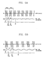
- Figures 5A and 5B are graphs showing a voltage applied to the fan motor through an apparatus for controlling a speed of the fan motor of the air-conditioner and a rotation speed in accordance with the present invention.
- the controller 201 When a rotation request signal for rotating the fan motor 204 is inputted by a user, the controller 201 outputs a predetermined duty ratio control signal corresponding to the rotation request signal to the triac 203.
- the controller 201 when a rotation request signal for rotating the fan motor 204 at 750 RPM (W1) is inputted by the user, the controller 201 outputs a predetermined duty ratio control signal (e.g., duty ratio 1/(1+0.5) corresponding to the rotation request signal to the triac 203. For example, the controller 201 turns on the triac 203 for one second (the interval S1) to apply a voltage to the fan motor 204.
- the triac 203 is turned on for an initial one second, the HIM 204 is rotated at maximum 880RPM.
- the controller 201 turns off the triac 203 for 0.5 seconds (the interval S2) in order to not apply the voltage to the HIM 204.
- the RPM of the HIM 204 is reduced for 0.5 seconds.
- 0.5 seconds means time so long as for the HIM 204 not to be stopped from rotation in consideration of inertia of the HIM 204 and a mechanical time constant.
- An average RPM (the minimum RPM) of the HIM 204 during the interval S2 measured through experimentation was 620RPM.
- the controller 201 turns on the triac 203 for one second (interval S3) again to apply a voltage to the HIM 204 for one second.
- the HIM 204 since the HIM 204 has been rotated at average 620RPM according to inertia, the HIM 204 becomes rotated at average 880RPM.
- the apparatus for controlling the speed is operated according to the duty ratio control signal (1/(1+0.5)
- the minimum RPM i.e., the average RPM while the triac 203 is turned off for 0.5 seconds
- the maximum RPM the average RPM while the triac 203 is turned on for one second
- an average value of the RPM of the fan motor (HIM) 204 is 750RPM (620RPM+880RPM)/2).
- the controller 201 when a rotation request signal for rotating the fan motor 204 at 560RPM (W2) is inputted by the user, the controller 201 outputs a predetermined duty ratio control signal (e.g., duty ratio 1/(1+1) corresponding to the rotation request signal to the triac 203. Namely, the controller 201 turns on the triac 203 for one second (the interval S4) to apply a voltage to the HIM 204. In this case, when the triac 203 is turned on for initial one second, the HIM 204 is rotated at the maximum 880RPM.
- a predetermined duty ratio control signal e.g., duty ratio 1/(1+1) corresponding to the rotation request signal
- the controller 201 turns on the triac 203 for one second (the interval S4) to apply a voltage to the HIM 204.
- the triac 203 is turned on for initial one second, the HIM 204 is rotated at the maximum 880RPM.
- the controller 201 turns off the triac 203 for one second (the interval S5) in order not to apply the voltage to the HIM 204 for one second. Then, since the voltage Vac is not supplied to the HIM 204 for one second, the RPM of the HIM 204 is reduced for one second (the HIM is rotated by inertia).
- 1 second means time so long as for the HIM 204 not to be stopped from rotation in consideration of inertia of the HIM 204 and a mechanical time constant.
- An average RPM (the minimum RPM) of the HIM 204 during the interval S5 measured through experimentation was 300RPM.
- the controller 201 turns on the triac 203 for one second (the interval S6) to apply the voltage to the HIM 204. Then, the HIM 204 is rotated at an average 820RPM. Namely, since the average RPM (300RPM) of the HIM 204 during the interval S5 is smaller than the average RPM (620RPM) during the interval S2, an average RPM (the maximum RPM) of the HIM 204 during the interval S6 measured through experimentation was 820RPM.
- the speed control range of the HIM 204 can be extended.
- the speed control range of the fan motor of the air-conditioner includes 560, 750 and 880RPM
- the present invention can be applied for an air-conditioner which requires a speed control range of 100RPM or above.
- the apparatus for controlling a speed of a fan motor of an air-conditioner in accordance with the present invention has such an advantage that the speed control range of the HIM can be extended by rotating the HIM based on a pre-set duty ratio of the triac and controlling an average value of the RPM of the rotated HIM.
Landscapes
- Engineering & Computer Science (AREA)
- Power Engineering (AREA)
- Physics & Mathematics (AREA)
- Fluid Mechanics (AREA)
- Chemical & Material Sciences (AREA)
- Combustion & Propulsion (AREA)
- Mechanical Engineering (AREA)
- General Engineering & Computer Science (AREA)
- Control Of Positive-Displacement Air Blowers (AREA)
- Control Of Ac Motors In General (AREA)
- Control Of Electric Motors In General (AREA)
- Air Conditioning Control Device (AREA)
Abstract
Description
- The present invention relates to an air-conditioner and, more particularly, to an apparatus for controlling a speed of a fan motor of an air-conditioner.
- In general, a single-phase induction motor is used as a fan motor of an air-conditioner. In order to generate rotating torque, the single-phase induction motor supplies a magnetizing current generating a rotating field and an induced current generated from a rotor to windings connected with an external power terminal.
- The single-phase induction motor has a limitation in enhancing efficiency due to a primary copper loss of a stator and a secondary copper loss of the rotor.
- In order to resolve such limitation, recently, a HIM (Hybrid Induction Motor) as shown in Figures 1 and 2 is used as a fan motor of the air-conditioner.
- Figure 1 is a schematic sectional view of the HIM in accordance with a conventional art, and Figure 2 is a schematic sectional top view taken along line B-B' of the HIM of Figure 1.
- As shown in Figures 1 and 2, a
bracket 104 of the conventional HIM 100 includes astator 105 and aninduction rotor 101 installed at an inner side of thestator 105. A plurality ofslots 108 are protrusively formed at an inner side of thestator 105 andcoils 103 for applying a current are wound at theslots 108. -
Aluminum rotor bars 112 are vertically inserted into a plurality of air gaps formed in an up/down direction at an edge of therotor 101, and thealuminum rotor bars 112 are connected by anend ring 102. - A rotating
shaft 109 for transferring a rotational force of therotor 101 to outside is installed in anair gap 110 formed at the center of theinduction rotor 101. The rotatingshaft 109 can be rotated by anoilless bearing 107 installed at thebracket 104. - A
permanent magnet rotor 106 for rotating therotor 101 with a strong magnetic flux while being rotated by rotating field generated from thestator 105 is installed between thestator 105 and theinduction rotor 101. - When an AC voltage is applied to the conventional HIM, the
permanent magnet rotor 106 is rotated by the current applied to thecoil 103 of thestator 105, and the rotatingpermanent magnet rotor 106 generates a rotating field with strong magnetic flux, to rotate theinduction rotator 101. At this time, thepermanent magnet rotor 106 in a low inertia state is separated from a fan (not shown) and rotated owing to the rotating field of thestator 105, and as a torque generating magnetic flux is supplied to theinduction rotor 101 owing to the rotating field of the permanent magnet rotor 10, theinduction rotor 101 is rotated. - In other words, when the
permanent magnet rotor 106 is rotated by the rotating field in an oval form generated from the stator of the distributed windings, thepermanent magnet rotor 106 generates rotating field with strong magnetic flux to make theinduction rotor 101 rotated, so that the HIM is operated with high efficiency and low noise. - Velocity characteristics of the conventional apparatus for controlling a speed of the fan motor of the air-conditioner and a general induction motor will now be described with reference to Figures 3 and 4.
- Figure 3 is a circuit diagram showing the construction of the apparatus for controlling a speed of the fan motor (HIM) in accordance with the conventional art, and Figure 4 is a graph showing speed characteristics of the conventional HIM and a general induction motor.
- As shown in Figure 3, when the apparatus for controlling a rotational speed of the fan motor by controlling a phase of a voltage applied to the fan motor (HIM) through one triac is applied for the HIM, a speed control range (i.e., 790-880RPM (revolution per minute) according to the voltage is limited as shown in Figure 4. Namely, the speed control range is limited to the 790-880RPM(880RPM-790RPM=90RPM) due to the
permanent magnet rotor 106. This causes a problem that the conventional apparatus for controlling the speed of the fan motor cannot be applied for air-conditioner which requires a speed control range or above 100RPM. - U.S. Patent No. 6,819,026 issued on November 16, 2004 also discloses an induction motor used as a fan motor of an air-conditioner.
- Therefore, an object of the present invention is to provide an apparatus for controlling a speed of a fan motor of an air-conditioner capable of extending a speed control range of a fan motor of an air-conditioner by controlling revolutions per minute (RPM) of the fan motor.
- To achieve these and other advantages and in accordance with the purpose of the present invention, as embodied and broadly described herein, there is provided an apparatus for controlling a speed of a HIM (Hybrid Induction Motor) in which in order to extend a speed control range of the HIM, an RPM of the HIM is controlled based on a pre-set duty ratio of a switching device electrically connected with the HIM.
- To achieve the above object, there is also provided an apparatus for controlling a speed of a fan motor of an air-conditioner with a fan motor having a stator, an induction rotor and a permanent magnet rotor installed between the stator and the induction rotor, including: a controller for generating a predetermined duty ratio control signal corresponding to a rotation request signal for rotating the fan motor inputted by a user; and a switching device for controlling the RPM of the fan motor by controlling a voltage applied to the fan motor according to the duty ratio control signal, wherein the duty ratio control signal controls a turn-on time and a turn-off time of the switching device.
- The foregoing and other objects, features, aspects and advantages of the present invention will become more apparent from the following detailed description of the present invention when taken in conjunction with the accompanying drawings.
- The accompanying drawings, which are included to provide a further understanding of the invention and are incorporated in and constitute a part of this specification, illustrate embodiments of the invention and together with the description serve to explain the principles of the invention.
- In the drawings:
- Figure 1 is a schematic sectional view of a HIM in accordance with a conventional art;
- Figure 2 is a schematic top view taken along line B-B' of the HIM of Figure 1;
- Figure 3 is a graph showing speed characteristics of the HIM in accordance with the conventional art and a general induction motor;
- Figure 4 is a block diagram showing the construction of an apparatus for controlling a speed of a fan motor of an air-conditioner in accordance with the present invention; and
- Figures 5A and 5B are graphs showing a voltage applied to the fan motor through an apparatus for controlling a speed of the fan motor of the air-conditioner and a rotation speed in accordance with the present invention.
- Several times of trial and error and experimentation have revealed that an apparatus for controlling a speed of a fan motor of an air-conditioner in accordance with the present invention can more effectively extend a speed control range when it is applied for a HIM (Hybrid Induction Motor) than applied for a general induction motor.
- An apparatus for controlling a speed of a fan motor of an air-conditioner capable of extending a speed control range of the fan motor (HIM) by controlling an average of an RPM (Revolutions Per Minute) of the fan motor of an air-conditioner in accordance with a preferred embodiment of the present invention will be described in detail with reference to Figures 4 and 5.
- Figure 4 is a block diagram showing the construction of an apparatus for controlling a speed of a fan motor of an air-conditioner in accordance with the present invention.
- As shown in Figure 4, the apparatus for controlling a speed of the fan motor of the air-conditioner includes: a
controller 201 for generating a predetermined duty ratio control signal corresponding to a rotation request signal for rotating the fan motor (HIM) 204 inputted by a user; and atriac 203 for controlling the RPM of the fan motor by controlling a voltage applied to the fan motor according to the duty ratio control signal, in order to extend a speed control range of thefan motor 204. - Preferably, a
memory 202 for storing pre-determined duty ratio control signals for controlling the RPM of thefan motor 204 is connected with thecontroller 201. - In the present invention, a switching device such as an inverter can be used in place of the
triac 203. - The duty ratio control signal is a signal for controlling a rate of a turn-on time and a turn-off time of the
triac 203 during one cycle. Namely, the duty ratio control signals turns on thetriac 203 during a first pre-set time and turns off thetriac 203 during a second pre-set time. - In other words, an average value of an RPM of the
HIM 203 according to various duty ratio control signals is calculated, a duty ratio control signal corresponding to the calculated average value is stored in thememory 202, and then, the average value of the RPM of thefan motor 204 is controlled based on the stored duty ratio control signal, thereby extending a speed control range of thefan motor 204. - When a rotation request signal for increasing the RPM of the
fan motor 204 is inputted, thecontroller 201 generates a duty ratio control signal for lengthening the turn-on time of thetriac 203 and shortening the turn-off time. Preferably, the turn-off time does not exceed 1 second. - Meanwhile, when a rotation request signal for reducing the RPM of the fan motor is inputted, the controller generates a duty ratio control signal for shortening the turn-on time of the
triac 203 and lengthening the turn-off time of thetriac 203. Preferably, the turn-off time of thetriac 203 does not exceed 1 second. - The operation of the apparatus for controlling the fan motor of the air-conditioner in accordance with the present invention will now be described in detail with reference to Figures 5A and 5B.
- Figures 5A and 5B are graphs showing a voltage applied to the fan motor through an apparatus for controlling a speed of the fan motor of the air-conditioner and a rotation speed in accordance with the present invention.
- First, when a rotation request signal for rotating the
fan motor 204 is inputted by a user, thecontroller 201 outputs a predetermined duty ratio control signal corresponding to the rotation request signal to thetriac 203. - With reference to Figure 5A, when a rotation request signal for rotating the
fan motor 204 at 750 RPM (W1) is inputted by the user, thecontroller 201 outputs a predetermined duty ratio control signal (e.g.,duty ratio 1/(1+0.5) corresponding to the rotation request signal to thetriac 203. For example, thecontroller 201 turns on thetriac 203 for one second (the interval S1) to apply a voltage to thefan motor 204. Herein, when thetriac 203 is turned on for an initial one second, the HIM 204 is rotated at maximum 880RPM. - Thereafter, the
controller 201 turns off thetriac 203 for 0.5 seconds (the interval S2) in order to not apply the voltage to theHIM 204. In this case, because the voltage Vac is not supplied to theHIM 204 for 0.5 seconds, the RPM of theHIM 204 is reduced for 0.5 seconds. Herein, 0.5 seconds means time so long as for theHIM 204 not to be stopped from rotation in consideration of inertia of theHIM 204 and a mechanical time constant. An average RPM (the minimum RPM) of theHIM 204 during the interval S2 measured through experimentation was 620RPM. - The
controller 201 turns on thetriac 203 for one second (interval S3) again to apply a voltage to theHIM 204 for one second. At this time, since the HIM 204 has been rotated at average 620RPM according to inertia, the HIM 204 becomes rotated at average 880RPM. An average RPM (the maximum RPM) of theHIM 204 during the interval S3 measured through experimentation was 880RPM. - Accordingly, when the apparatus for controlling the speed is operated according to the duty ratio control signal (1/(1+0.5)), since the minimum RPM (i.e., the average RPM while the
triac 203 is turned off for 0.5 seconds) of theHIM 204 measured through experimentation was 620RPM and the maximum RPM (the average RPM while thetriac 203 is turned on for one second) measured through experimentation was 880RPM, an average value of the RPM of the fan motor (HIM) 204 is 750RPM (620RPM+880RPM)/2). - With reference to Figure 5B, when a rotation request signal for rotating the
fan motor 204 at 560RPM (W2) is inputted by the user, thecontroller 201 outputs a predetermined duty ratio control signal (e.g.,duty ratio 1/(1+1) corresponding to the rotation request signal to thetriac 203. Namely, thecontroller 201 turns on thetriac 203 for one second (the interval S4) to apply a voltage to theHIM 204. In this case, when thetriac 203 is turned on for initial one second, theHIM 204 is rotated at the maximum 880RPM. - Thereafter, the
controller 201 turns off thetriac 203 for one second (the interval S5) in order not to apply the voltage to theHIM 204 for one second. Then, since the voltage Vac is not supplied to theHIM 204 for one second, the RPM of theHIM 204 is reduced for one second (the HIM is rotated by inertia). Herein, 1 second means time so long as for theHIM 204 not to be stopped from rotation in consideration of inertia of theHIM 204 and a mechanical time constant. An average RPM (the minimum RPM) of theHIM 204 during the interval S5 measured through experimentation was 300RPM. - Thereafter, the
controller 201 turns on thetriac 203 for one second (the interval S6) to apply the voltage to theHIM 204. Then, theHIM 204 is rotated at an average 820RPM. Namely, since the average RPM (300RPM) of theHIM 204 during the interval S5 is smaller than the average RPM (620RPM) during the interval S2, an average RPM (the maximum RPM) of theHIM 204 during the interval S6 measured through experimentation was 820RPM. - Accordingly, when the apparatus for controlling the speed is operated according to the duty ratio control signal (1/(1+1), since the minimum RPM (the average RPM while the triac is turned on during one second) of the
HIM 204 measured through experimentation was 300RPM and the maximum RPM (the average RPM while the triac is turned on for one second) is 820RPM, an average value of the RPM of theHIM 204 is 560RPM (300RPM+820RPM)/2=560RPM). - Consequently, by rotating the
HIM 204 according to the various duty ratios of the triac, previously calculating an average value of the RPM of theHIM 204 and controlling the turn-one time/turn-off time of thetriac 203 according to the duty ratio control signal corresponding to the previously calculated average value, the speed control range of theHIM 204 can be extended. For example, when the apparatus for controlling a speed of the fan motor of the air-conditioner is applied for theHIM 204, the speed control range of the fan motor of the air-conditioner includes 560, 750 and 880RPM, the present invention can be applied for an air-conditioner which requires a speed control range of 100RPM or above. - As so far described, the apparatus for controlling a speed of a fan motor of an air-conditioner in accordance with the present invention has such an advantage that the speed control range of the HIM can be extended by rotating the HIM based on a pre-set duty ratio of the triac and controlling an average value of the RPM of the rotated HIM.
- As the present invention may be embodied in several forms without departing from the spirit or essential characteristics thereof, it should also be understood that the above-described embodiments are not limited by any of the details of the foregoing description, unless otherwise specified, but rather should be construed broadly within its spirit and scope as defined in the appended claims, and therefore all changes and modifications that fall within the metes and bounds of the claims, or equivalence of such metes and bounds are therefore intended to be embraced by the appended claims.
Claims (13)
- An apparatus for controlling a speed of a HIM (Hybrid Induction Motor), wherein, in order to extend a speed control range of the HIM, an average RPM (revolution per minute) of the HIM is controlled based on a pre-set duty ratio of a switching device electrically connected with the HIM.
- The apparatus of claim 1, wherein the switching device is a triac.
- The apparatus of claim 1, wherein the switching device is an inverter.
- The apparatus of claim 1, comprising:a controller for generating a predetermined duty ratio control signal corresponding to a rotation request signal for rotating the HIM inputted by a user; anda triac for controlling the RPM of the fan motor by controlling a voltage applied to the fan motor according to the duty ratio control signal,wherein the duty ratio control signal controls a turn-on time and a turn-off time of the switching device.
- An apparatus for controlling a speed of a fan motor of an air-conditioner with a fan motor having a stator, an induction rotor and a permanent magnet rotor installed between the stator and the induction rotor, comprising:a controller for generating a predetermined duty ratio control signal corresponding to a rotation request signal for rotating the fan motor inputted by a user; anda switching device for controlling an average value of RPM (revolution per minute) of the fan motor by controlling a voltage applied to the fan motor according to the duty ratio control signal, wherein the duty ratio control signal controls a turn-on time and a turn-off time of the switching device.
- The apparatus of claim 5, wherein the switching device is an inverter.
- The apparatus of claim 5, wherein the switching device is a triac.
- The apparatus of claim 7, wherein the duty ratio control signal turns on the triac during a first pre-set time and turns off the triac during a second pre-set time.
- The apparatus of claim 7, wherein when a rotation request signal for increasing the RPM of the fan motor is inputted, the controller generates a duty ratio control signal for lengthening the turn-on time of the triac and shortening the turn-off time of the triac, and when a rotation request signal for reducing the RPM of the fan motor is inputted, the controller generates a duty ratio control signal for shortening the turn-on time of the triac and lengthening the turn-off time of the triac.
- The apparatus of claim 9, wherein the turn-off time of the triac is not greater than one second.
- The apparatus of claim 10, wherein the controller controls an average value of an average RPM of the fan motor while the triac is turned off and an average RPM of the fan motor while the triac is turned on, thereby extending the speed control range of the fan motor.
- The apparatus of claim 11, further comprising:a memory for storing the predetermined duty ratio control signal.
- The apparatus of claim 12, wherein the fan motor is rotated by inertia while the triac is turned off and the fan motor is rotated by the voltage while the triac is turned on.
Applications Claiming Priority (1)
| Application Number | Priority Date | Filing Date | Title |
|---|---|---|---|
| KR1020040093242A KR100748518B1 (en) | 2004-11-15 | 2004-11-15 | Fan motor speed changer of air conditioner |
Publications (3)
| Publication Number | Publication Date |
|---|---|
| EP1657811A2 true EP1657811A2 (en) | 2006-05-17 |
| EP1657811A3 EP1657811A3 (en) | 2007-05-16 |
| EP1657811B1 EP1657811B1 (en) | 2014-11-12 |
Family
ID=35911317
Family Applications (1)
| Application Number | Title | Priority Date | Filing Date |
|---|---|---|---|
| EP05005807.2A Expired - Lifetime EP1657811B1 (en) | 2004-11-15 | 2005-03-17 | Apparatus for controlling speed of fan motor of air-conditioner having an induction rotor and a permanent maget rotor |
Country Status (5)
| Country | Link |
|---|---|
| US (1) | US7271565B2 (en) |
| EP (1) | EP1657811B1 (en) |
| JP (1) | JP2006149178A (en) |
| KR (1) | KR100748518B1 (en) |
| CN (1) | CN1777020B (en) |
Families Citing this family (3)
| Publication number | Priority date | Publication date | Assignee | Title |
|---|---|---|---|---|
| KR100765167B1 (en) * | 2006-08-31 | 2007-10-12 | 삼성전자주식회사 | Fan motor control method of air conditioner |
| CN101313458B (en) * | 2006-10-19 | 2012-02-08 | Lg电子株式会社 | Driving mechanism for fan using multiple HIM motors |
| US20100131106A1 (en) * | 2008-10-30 | 2010-05-27 | Malee Kriangkanont | Method for efficient operation of cooling system |
Family Cites Families (31)
| Publication number | Priority date | Publication date | Assignee | Title |
|---|---|---|---|---|
| US3573577A (en) * | 1969-06-30 | 1971-04-06 | Allis Chalmers Mfg Co | Control system for brushless synchronous motor |
| US4038589A (en) * | 1975-11-20 | 1977-07-26 | Westinghouse Electric Corporation | Controlled post-synchronizing on brushless synchronous motors |
| FR2511209B1 (en) * | 1981-08-06 | 1985-08-16 | Cem Comp Electro Mec | DIRECT CURRENT, CYLINDRICAL GAP AND PERMANENTLY DRIVEN MACHINE |
| US4463304A (en) * | 1982-07-26 | 1984-07-31 | Franklin Electric Co., Inc. | High voltage motor control circuit |
| US4453101A (en) * | 1983-09-27 | 1984-06-05 | General Electric Company | Amortisseur bar with improved interface between free conductor bars and amortisseur ring |
| KR930004379B1 (en) * | 1983-11-16 | 1993-05-27 | 가부시끼가이샤 히다찌세이사꾸쇼 | Refrigerator controls |
| US4658195A (en) * | 1985-05-21 | 1987-04-14 | Pt Components, Inc. | Motor control circuit with automatic restart of cut-in |
| FR2572229B1 (en) * | 1984-10-22 | 1987-04-17 | Rfb Electromecanismes | IMPROVED MAGNET ROTATING MACHINE |
| US5200684A (en) * | 1988-04-18 | 1993-04-06 | Whirlpool Corporation | Electrical motor monitoring system for a domestic appliance |
| US5038091A (en) * | 1989-08-11 | 1991-08-06 | Whirlpool Corporation | Electronic control for an appliance |
| JPH04208086A (en) * | 1990-11-30 | 1992-07-29 | Daikin Ind Ltd | Motor controller |
| CN1030418C (en) * | 1991-01-03 | 1995-11-29 | 北京市西城区新开通用试验厂 | Controllable varioplex brushless wound motor |
| JPH04344190A (en) | 1991-05-22 | 1992-11-30 | Fuji Electric Co Ltd | Speed control method for single-phase capacitor motor |
| US5440219A (en) * | 1993-05-21 | 1995-08-08 | Wilkerson; Alan W. | Induction motor speed control having improved sensing of motor operative conditions |
| JPH07180895A (en) | 1993-12-24 | 1995-07-18 | Sharp Corp | Air conditioner |
| US5592062A (en) * | 1994-03-08 | 1997-01-07 | Bach; Daniel G. | Controller for AC induction motors |
| US5589753A (en) * | 1994-04-11 | 1996-12-31 | Andrew S. Kadah | Rate effect motor start circuit |
| US5786673A (en) * | 1995-09-06 | 1998-07-28 | Johnson Consulting, Inc. | Electric motor |
| KR970031215A (en) * | 1995-11-11 | 1997-06-26 | 구자홍 | Pulse Width Modulated Brushless Motor |
| JP3476114B2 (en) * | 1996-08-13 | 2003-12-10 | 富士通株式会社 | Stereoscopic display method and apparatus |
| JP3050851B2 (en) | 1998-07-06 | 2000-06-12 | 文人 小松 | Synchronous motor |
| KR100354776B1 (en) * | 2000-03-30 | 2002-11-07 | 엘지전자 주식회사 | Method for driving a Switched Reluctance Motor |
| US6346790B1 (en) * | 2000-04-12 | 2002-02-12 | Emerson Electric Co. | Induction motor system with an induction motor and an electrically isolated voltage modulation motor controller |
| US6504338B1 (en) * | 2001-07-12 | 2003-01-07 | Varidigm Corporation | Constant CFM control algorithm for an air moving system utilizing a centrifugal blower driven by an induction motor |
| US6784634B2 (en) * | 2001-09-14 | 2004-08-31 | Edwin A. Sweo | Brushless doubly-fed induction machine control |
| JP4158024B2 (en) * | 2002-04-30 | 2008-10-01 | 株式会社富士通ゼネラル | Induction motor |
| EP1416616B1 (en) | 2002-10-26 | 2010-06-09 | LG Electronics Inc. | Electric motor |
| US20040164695A1 (en) * | 2003-02-26 | 2004-08-26 | William M. Hallidy | Electrodynamic machines and components therefor and methods of making and using same |
| US7239057B2 (en) | 2003-03-04 | 2007-07-03 | Lg Electronics Inc. | Single phase induction motor |
| KR100655996B1 (en) * | 2003-07-09 | 2006-12-11 | 마츠시타 덴끼 산교 가부시키가이샤 | Synchronous induction motor and electric hermetic compressor using the same |
| US7045986B2 (en) * | 2004-02-20 | 2006-05-16 | Honeywell International Inc. | Position sensing method and apparatus for synchronous motor generator system |
-
2004
- 2004-11-15 KR KR1020040093242A patent/KR100748518B1/en not_active Expired - Fee Related
-
2005
- 2005-03-04 US US11/071,455 patent/US7271565B2/en not_active Expired - Fee Related
- 2005-03-16 JP JP2005074747A patent/JP2006149178A/en active Pending
- 2005-03-17 EP EP05005807.2A patent/EP1657811B1/en not_active Expired - Lifetime
- 2005-04-06 CN CN2005100648227A patent/CN1777020B/en not_active Expired - Fee Related
Also Published As
| Publication number | Publication date |
|---|---|
| EP1657811B1 (en) | 2014-11-12 |
| CN1777020B (en) | 2010-10-06 |
| JP2006149178A (en) | 2006-06-08 |
| KR20060054627A (en) | 2006-05-23 |
| US20060113950A1 (en) | 2006-06-01 |
| US7271565B2 (en) | 2007-09-18 |
| CN1777020A (en) | 2006-05-24 |
| KR100748518B1 (en) | 2007-08-13 |
| EP1657811A3 (en) | 2007-05-16 |
Similar Documents
| Publication | Publication Date | Title |
|---|---|---|
| US7081733B2 (en) | Speed control system of fan motor of air conditioner | |
| JPWO2018078835A1 (en) | Air conditioner and control method of air conditioner | |
| JPH04275091A (en) | Drive controller for commutatorless motor | |
| JPWO2018078840A1 (en) | Driving device, air conditioner, and electric motor driving method | |
| US20080290824A1 (en) | Apparatus and method for controlling operation of motor | |
| JPWO2019021373A1 (en) | Driving device, compressor, air conditioner, and driving method | |
| JP2001298977A (en) | Soft start of an electronic motor operated by a microcontroller using a table drive equation with variable timing | |
| JP6710336B2 (en) | Driving device, air conditioner, and driving method | |
| WO2019021452A1 (en) | Drive device, compressor, air conditioner, and method for driving embedded permanent magnet-type electric motor | |
| JPWO2018078838A1 (en) | DRIVE DEVICE, AIR CONDITIONER, AND COMPRESSOR CONTROL METHOD | |
| EP1667319B1 (en) | Apparatus for controlling speed of fan motor of air-conditioner | |
| JP4723510B2 (en) | Single-phase induction motor starting system | |
| JP5428746B2 (en) | Brushless DC motor driving apparatus and electric apparatus using the same | |
| JPH08205581A (en) | Switched reluctance motor | |
| EP1657811B1 (en) | Apparatus for controlling speed of fan motor of air-conditioner having an induction rotor and a permanent maget rotor | |
| JP7019072B2 (en) | Air conditioner and control method of air conditioner | |
| JP3050851B2 (en) | Synchronous motor | |
| US20020145397A1 (en) | Electronically commutated electric motor | |
| EP1804369A2 (en) | Apparatus and method for varying speed of hybrid induction motor | |
| JPH05252708A (en) | Single-phase induction start type synchronous motor | |
| JPH0515128A (en) | Electric motor of compressor for refrigeration equipment | |
| JP2004222460A (en) | Synchronous motor | |
| JPH05328787A (en) | Brushless motor drive |
Legal Events
| Date | Code | Title | Description |
|---|---|---|---|
| PUAI | Public reference made under article 153(3) epc to a published international application that has entered the european phase |
Free format text: ORIGINAL CODE: 0009012 |
|
| AK | Designated contracting states |
Kind code of ref document: A2 Designated state(s): AT BE BG CH CY CZ DE DK EE ES FI FR GB GR HU IE IS IT LI LT LU MC NL PL PT RO SE SI SK TR |
|
| AX | Request for extension of the european patent |
Extension state: AL BA HR LV MK YU |
|
| PUAL | Search report despatched |
Free format text: ORIGINAL CODE: 0009013 |
|
| AK | Designated contracting states |
Kind code of ref document: A3 Designated state(s): AT BE BG CH CY CZ DE DK EE ES FI FR GB GR HU IE IS IT LI LT LU MC NL PL PT RO SE SI SK TR |
|
| AX | Request for extension of the european patent |
Extension state: AL BA HR LV MK YU |
|
| RIC1 | Information provided on ipc code assigned before grant |
Ipc: H02K 17/04 20060101ALI20070410BHEP Ipc: H02P 25/00 20060101AFI20060323BHEP Ipc: H02K 1/27 20060101ALI20070410BHEP Ipc: H02K 16/02 20060101ALI20070410BHEP Ipc: H02P 27/16 20060101ALI20070410BHEP Ipc: F24F 11/00 20060101ALI20070410BHEP |
|
| 17P | Request for examination filed |
Effective date: 20070618 |
|
| AKX | Designation fees paid |
Designated state(s): DE FR GB IT |
|
| 17Q | First examination report despatched |
Effective date: 20080408 |
|
| GRAP | Despatch of communication of intention to grant a patent |
Free format text: ORIGINAL CODE: EPIDOSNIGR1 |
|
| INTG | Intention to grant announced |
Effective date: 20140522 |
|
| GRAS | Grant fee paid |
Free format text: ORIGINAL CODE: EPIDOSNIGR3 |
|
| GRAA | (expected) grant |
Free format text: ORIGINAL CODE: 0009210 |
|
| AK | Designated contracting states |
Kind code of ref document: B1 Designated state(s): DE FR GB IT |
|
| REG | Reference to a national code |
Ref country code: GB Ref legal event code: FG4D |
|
| REG | Reference to a national code |
Ref country code: DE Ref legal event code: R096 Ref document number: 602005045127 Country of ref document: DE Effective date: 20141224 |
|
| REG | Reference to a national code |
Ref country code: DE Ref legal event code: R097 Ref document number: 602005045127 Country of ref document: DE |
|
| PLBE | No opposition filed within time limit |
Free format text: ORIGINAL CODE: 0009261 |
|
| STAA | Information on the status of an ep patent application or granted ep patent |
Free format text: STATUS: NO OPPOSITION FILED WITHIN TIME LIMIT |
|
| 26N | No opposition filed |
Effective date: 20150813 |
|
| GBPC | Gb: european patent ceased through non-payment of renewal fee |
Effective date: 20150317 |
|
| PG25 | Lapsed in a contracting state [announced via postgrant information from national office to epo] |
Ref country code: IT Free format text: LAPSE BECAUSE OF FAILURE TO SUBMIT A TRANSLATION OF THE DESCRIPTION OR TO PAY THE FEE WITHIN THE PRESCRIBED TIME-LIMIT Effective date: 20141112 |
|
| REG | Reference to a national code |
Ref country code: FR Ref legal event code: ST Effective date: 20151130 |
|
| PG25 | Lapsed in a contracting state [announced via postgrant information from national office to epo] |
Ref country code: GB Free format text: LAPSE BECAUSE OF NON-PAYMENT OF DUE FEES Effective date: 20150317 |
|
| PG25 | Lapsed in a contracting state [announced via postgrant information from national office to epo] |
Ref country code: FR Free format text: LAPSE BECAUSE OF NON-PAYMENT OF DUE FEES Effective date: 20150331 |
|
| PGFP | Annual fee paid to national office [announced via postgrant information from national office to epo] |
Ref country code: DE Payment date: 20180206 Year of fee payment: 14 |
|
| REG | Reference to a national code |
Ref country code: DE Ref legal event code: R119 Ref document number: 602005045127 Country of ref document: DE |
|
| PG25 | Lapsed in a contracting state [announced via postgrant information from national office to epo] |
Ref country code: DE Free format text: LAPSE BECAUSE OF NON-PAYMENT OF DUE FEES Effective date: 20191001 |