EP1657686A2 - Gaming machine - Google Patents
Gaming machine Download PDFInfo
- Publication number
- EP1657686A2 EP1657686A2 EP06003130A EP06003130A EP1657686A2 EP 1657686 A2 EP1657686 A2 EP 1657686A2 EP 06003130 A EP06003130 A EP 06003130A EP 06003130 A EP06003130 A EP 06003130A EP 1657686 A2 EP1657686 A2 EP 1657686A2
- Authority
- EP
- European Patent Office
- Prior art keywords
- liquid crystal
- gaming machine
- display panel
- reel
- crystal display
- Prior art date
- Legal status (The legal status is an assumption and is not a legal conclusion. Google has not performed a legal analysis and makes no representation as to the accuracy of the status listed.)
- Granted
Links
Images



Classifications
-
- G—PHYSICS
- G02—OPTICS
- G02B—OPTICAL ELEMENTS, SYSTEMS OR APPARATUS
- G02B6/00—Light guides; Structural details of arrangements comprising light guides and other optical elements, e.g. couplings
- G02B6/0001—Light guides; Structural details of arrangements comprising light guides and other optical elements, e.g. couplings specially adapted for lighting devices or systems
- G02B6/0011—Light guides; Structural details of arrangements comprising light guides and other optical elements, e.g. couplings specially adapted for lighting devices or systems the light guides being planar or of plate-like form
- G02B6/0081—Mechanical or electrical aspects of the light guide and light source in the lighting device peculiar to the adaptation to planar light guides, e.g. concerning packaging
- G02B6/0086—Positioning aspects
- G02B6/0088—Positioning aspects of the light guide or other optical sheets in the package
-
- G—PHYSICS
- G07—CHECKING-DEVICES
- G07F—COIN-FREED OR LIKE APPARATUS
- G07F17/00—Coin-freed apparatus for hiring articles; Coin-freed facilities or services
- G07F17/32—Coin-freed apparatus for hiring articles; Coin-freed facilities or services for games, toys, sports, or amusements
- G07F17/3202—Hardware aspects of a gaming system, e.g. components, construction, architecture thereof
-
- G—PHYSICS
- G07—CHECKING-DEVICES
- G07F—COIN-FREED OR LIKE APPARATUS
- G07F17/00—Coin-freed apparatus for hiring articles; Coin-freed facilities or services
- G07F17/32—Coin-freed apparatus for hiring articles; Coin-freed facilities or services for games, toys, sports, or amusements
- G07F17/3202—Hardware aspects of a gaming system, e.g. components, construction, architecture thereof
- G07F17/3204—Player-machine interfaces
- G07F17/3211—Display means
-
- G—PHYSICS
- G02—OPTICS
- G02B—OPTICAL ELEMENTS, SYSTEMS OR APPARATUS
- G02B6/00—Light guides; Structural details of arrangements comprising light guides and other optical elements, e.g. couplings
- G02B6/0001—Light guides; Structural details of arrangements comprising light guides and other optical elements, e.g. couplings specially adapted for lighting devices or systems
- G02B6/0011—Light guides; Structural details of arrangements comprising light guides and other optical elements, e.g. couplings specially adapted for lighting devices or systems the light guides being planar or of plate-like form
- G02B6/0033—Means for improving the coupling-out of light from the light guide
- G02B6/005—Means for improving the coupling-out of light from the light guide provided by one optical element, or plurality thereof, placed on the light output side of the light guide
- G02B6/0051—Diffusing sheet or layer
Definitions
- this type of gaming machine includes, for example, a slot machine.
- the slot machine comprises three reels embedded behind its front panel.
- Each reel comprises a reel band affixed on the outer periphery of its reel drum, and various designs are drawn on the outer periphery of the reel band. These designs may be viewed by a player through three windows formed in the front panel.
- the reel display window unit 39 is mounted on the machine front panel 38 such that, as shown in Fig. 3(a), brackets 39ba provided on the reel glass base 39b and protruding upward and downward are screwed on the rear of the machine front panel 38 with screws 39j, respectively. Note that in Fig. 4(b), each bracket 39ba provided on the reel glass base 39b is not shown.
- Major input signal generation means for generating input signals required for the microcomputer 63 to produce control signals include an inserted medal sensor 8S for detecting any medal inserted through the medal insertion slot 8, a start switch 30S for detecting any operation of the start lever 30, the above-described deposited-medal insertion switches 25-27, and the deposited-medal adjusting switch 29.
- a reel position detecting circuit 77 for detecting the rotational position of each reel 2, 3, 4 upon receipt of an output pulse signal from the photosensor 49.
- the photosensor 49 is included in the driving mechanism of each reel 2-4 and not shown in this figure.
- the peripheral corner portions in the rear face side of the openings 5c, 6c and 7c formed in the rear holder 39h are removed therefrom. In this case, when a player observes the reels 2-4 behind the liquid crystal panel 39d through the transparent acryl plate 39a, as demonstrated with an arrow in Fig. 3(b), the peripheral corner portions are prevented from being viewed by the player.
- the liquid crystal display panel disposed in front of the variable display means for variably displaying designs serves as a new machine component for performing game effects.
- a base frame and a panel frame are interposed between the transparent plate on the machine surface and the liquid crystal display panel.
- the display unit of the liquid crystal display panel for displaying game effects is disposed in a position recessed from the transparent plate. Accordingly, new game effects can be performed on the liquid crystal display panel, which facilitates maintaining the novelty of game effects.
- the liquid crystal display panel is located in a recessed position, its display unit is provided with depth feeling. In addition, blind spots in viewing the display unit are eliminated, and thus the display unit can be clearly viewed up to its edge.
Landscapes
- Physics & Mathematics (AREA)
- General Physics & Mathematics (AREA)
- Optics & Photonics (AREA)
- Slot Machines And Peripheral Devices (AREA)
- Display Devices Of Pinball Game Machines (AREA)
- Nitrogen And Oxygen Or Sulfur-Condensed Heterocyclic Ring Systems (AREA)
- Eye Examination Apparatus (AREA)
- Telephone Function (AREA)
- Two-Way Televisions, Distribution Of Moving Picture Or The Like (AREA)
- Acyclic And Carbocyclic Compounds In Medicinal Compositions (AREA)
- Confectionery (AREA)
- Memory System Of A Hierarchy Structure (AREA)
Abstract
Description
- This invention relates to a gaming machine comprising a transparent electric display panel disposed in front of variable display means for variably displaying designs.
- Conventionally, this type of gaming machine includes, for example, a slot machine. The slot machine comprises three reels embedded behind its front panel. Each reel comprises a reel band affixed on the outer periphery of its reel drum, and various designs are drawn on the outer periphery of the reel band. These designs may be viewed by a player through three windows formed in the front panel.
- A slot machine game is started when the player's operation of a start lever causes each reel to rotate and a moving sequence of designs is variably displayed in each window. Subsequently, the player's operation of a stop button causes each reel to stop rotating, and designs corresponding to the operation timing of the stop button are stop-displayed in each window. At this time, if any predetermined combination of designs is stop-displayed in the windows, a winning occurs.
- During the game, the slot machine game provides effects such as blinking lamps embedded in each reel or displaying character designs on a liquid crystal display device provided below the windows of the front panel.
- In conventional gaming machines described above, the novelty of game effects is maintained by changing the blinking pattern of the lamps embedded in the reels, changing effect contents given by character designs displayed on the liquid crystal display device, or otherwise. However, in the conventional gaming machines described above, the machine components of the gaming machine for effecting game effects have been well-established. Accordingly, there are some difficulties in maintaining the novelty of game effects.
- To solve these problems, this invention provides a gaming machine comprising: variable display means for variably displaying designs; a transparent liquid crystal display panel disposed in front of the variable display means through which the variable display means is able to be seen; a liquid crystal holder for holding the periphery of the display unit of the liquid crystal display panel on a rear side thereof; a panel frame for holding the periphery of a display unit of the liquid crystal display panel on a front side thereof; a light guiding plate for guiding light emitted from a light source to the rear side of the liquid crystal display panel; diffusion means for diffusing the light guided by the light guiding plate to equalize the light which illuminates the liquid crystal display panel; a base frame attached in front of the machine for supporting the liquid crystal holder, panel frame, light guiding plate and diffusion means such that the front of the display unit of the liquid crystal display panel has an opening; a transparent plate disposed in front of the base frame for closing the opening; and a rear holder for holding the liquid crystal holder, panel frame, light guiding plate and diffusion means supported by the base frame on the base frame from behind, and for reflecting the light emitted on the light guiding plate to the side of the liquid crystal display panel, the rear holder having one or more windows allowing the designs variably displayed in the variable display means to be observed.
- According to this configuration, the liquid crystal display panel disposed in front of the variable display means for variably displaying designs serves as a new machine component for performing game effects. Further, a base frame and a panel frame are interposed between the transparent plate on the machine surface and the liquid crystal display panel. As a result, the display unit of the liquid crystal display panel for displaying game effects is disposed in a position recessed from the transparent plate.
In another aspect, the present invention provides a gaming machine comprising: variable display means for variably displaying designs; a transparent liquid crystal display panel disposed in front of the variable display means through which the variable display means is able to be seen; a liquid crystal holder for holding the periphery of the display unit of the liquid crystal display panel; a light guiding plate for guiding light emitted from a light source to the rear side of the liquid crystal display panel; diffusion means for diffusing the light guided by the light guiding plate to equalize the light which illuminates the liquid crystal display panel; a black base frame attached in front of the machine for supporting the liquid crystal holder, the light guiding plate and the diffusion means such that the front of the display unit of the liquid crystal display panel has an opening; a transparent plate disposed in front of the base frame for closing the opening; and a rear holder for holding, the liquid crystal holder, the light guiding plate and the diffusion means supported by the base frame on the base frame from behind, and for reflecting the light emitted on the light guiding plate to the side of the liquid crystal display panel, the rear holder having one or more windows allowing the designs variably displayed in the variable display means to be observed.
Furthermore, the present invention provides a gaming machine comprising: variable display means for variably displaying designs; and a front display means disposed in front of the variable display means, wherein the front display means includes an electrical display device for allowing the variable display means to be observed therethrough and a rear holder for holding the electrical display device from a rear side thereof, the rear holder having one or more windows allowing the designs variably displayed in the variable display means to be observed, and that the peripheral corner portions in the rear side of the windows are removed therefrom.
The present invention provides a gaming machine comprising: variable display means for variably displaying designs; and front display means disposed in front of the variable display means, wherein the front display means includes a transparent liquid crystal display panel through which the variable display means is able to be seen, a light guiding plate for guiding light emitted from a light source to the entire of the liquid crystal display panel, and diffusion means for diffusing the light guided by the light guiding plate to equalize the light which illuminates the liquid crystal display panel, and in the light guiding plate and diffusion means, transparent areas for ensuring the visibility of the variable display of the variable display means are formed.
The present invention provides a gaming machine comprising: variable display means for variably displaying designs in a plurality of rows; and front display means disposed in front of the variable display means, wherein the front display means includes a transparent liquid crystal display panel through which the variable display means is able to be seen, and a light guiding plate for guiding light emitted from a light source to the entire of the liquid crystal display panel; and in the light guiding plate, transparent areas for ensuring the visibility of the variable display of the variable display means are individually formed corresponding to the plurality of rows. -
- Fig. 1 is a front view showing an appearance of a slot machine in accordance with an embodiment of this invention;
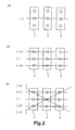
- Fig. 2 shows how the pay lines depicted on the display windows of the slot machine in accordance with this embodiment are sequentially activated;
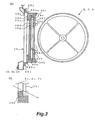
- Fig. 3 is a vertical cross-sectional view of the reel display window unit of the slot machine in accordance with this embodiment;
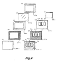
- Fig. 4 is an exploded perspective view of the reel display window unit shown in Fig. 3;
- Fig. 5 shows symbols drawn on the outer periphery of the reels of the slot machine in accordance with this embodiment;
- Fig. 6 is a perspective view showing a rotatable reel unit of the slot machine in accordance with this embodiment;
- Fig. 7 is a perspective view showing a structure of a rotatable reel constituting the rotatable reel unit shown in Fig. 6;
- Fig. 8 shows a symbol combination drawn on a payout display unit of the slot machine in accordance with this embodiment;
- Fig. 9 is a block diagram showing a circuit configuration arranged on a main control board of the slot machine in accordance with this embodiment; and
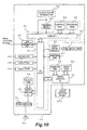
- Fig. 10 is a block diagram showing a circuit configuration arranged on a sub-control board of the slot machine in accordance with this embodiment.
- An embodiment will now be described in which a gaming machine in accordance with this invention is applied to a slot machine.
- Fig. 1 is a front view showing an appearance of a
slot machine 1 in accordance with this embodiment. - Inside a cabinet at the center of the main body of the
slot machine 1, threereels reels reel display window unit 39 is provided in front of these reels 2-4. Throughdisplay windows display window unit 39, symbols drawn on thereels display window unit 39 where three of them are horizontal and two diagonal. Furthermore, below the display windows 5-7, on the right side, aninsertion slot 8 is provided through which a player can insert one or more medals serving as gaming media. - When a player inserts one medal into the
medal insertion slot 8 prior to starting a game, one horizontal center pay line L1 is activated as shown in Fig. 2(a). When two medals are inserted, two upper and lower horizontal pay lines L2A and L2B are added thereto, and thus three horizontal pay lines L1, L2A, and L2B are activated as shown in Fig. 2 (b) . Furthermore, when three medals are inserted, all the five pay lines L1, L2A, L2B, L3A, and L3B are activated as shown in Fig. 2(c). A circle sign shown in Fig. 2 represents a symbol drawn on each reel 2-4. - On a machine front panel 38 to the left of the display windows 5-7, from the top, there are four chance LEDs (light emitting diodes) 9-12, three game operation indicator lamps 13-15, a deposited number of game
medals display unit 16, and astart lamp 17 provided. The chance LEDs 9-12 and the game operation indicator lamps 13-15 are controllably lighted up in accordance with the game status to inform a player of the current game status. The deposited number of gamemedals display unit 16 is composed of three digits of seven-segment LEDs and displays the number of medals currently credited within the machine. Thestart lamp 17 is blinked when each reel 2-4 can be actuated. - On the machine front panel 38 to the right of the display windows 5-7, from the top, there are a bonus
count display unit 18, aWIN lamp 19, number of payoutmedals display unit 20, and aninsert lamp 21 provided. The bonuscount display unit 18 is composed of three digits of seven-segment LEDs and digitally displays, when a player wins a bonus game, the remaining number of times the player could win the RB game and JAC game described below. TheWIN lamp 19 is lighted up when a winning combination of symbols lines up on any activated pay line. The number of payoutmedals display unit 20 is composed of three digits of seven-segment LEDs and displays the number of medals paid out due to the winning. Theinsert lamp 21 is lighted up when theinsertion slot 8 can accept the insertion of medals. - The reel
display window unit 39 comprises aliquid crystal panel 39d (described below) stacked thereon as an electric display panel. Theliquid crystal panel 39d may display various game information and game effect image. Below the left-hand machine front panel 38, there are across key 23, anA-button 24, a B-button 25, one-deposited-medal insertion switch 26, two-deposited-medal insertion switch 27, and three-deposited-medal insertion switch 28 provided. Thecross key 23 is switched in four directions of up, down, left, and right, and is operated in conjunction with theA-button 24 and B-button 25 for use in selecting information to be displayed on theliquid crystal panel 39d. The deposited-medal insertion switches 26-28 are used in betting one to three medals on one game instead of inserting medals into themedal insertion slot 8 when the deposited number of gamemedals display unit 16 is displaying the number of credited medals. - Below the reel
display window unit 39, from the left, there are a deposited-medal adjusting switch 29, astart lever 30, andstop buttons start lever 30 constitutes game starting means for starting a game. The deposited-medal adjusting switch 29 is used in adjusting the medals credited within the machine. Operation of thestart lever 30 causes each reel 2-4 to start rotating simultaneously. The stop buttons 31-33, disposed corresponding to the reels 2-4, respectively, are activated for operation when the rotating of each reel 2-4 reaches a predetermined speed, and stop the rotating of respective reels 2-4 in response to the player's operation. The stop buttons 31-33 constitute variable display stopping means for stopping the rotating display of the reels 2-4. - A
medal receiving tray 34 is provided at the front bottom of theslot machine 1. Themedal receiving tray 34 serves to store medals paid out of amedal payout opening 35. At the front top of theslot machine 1, apayout display unit 36 is provided for displaying how many medals will be paid out for winning. - Fig. 3(a) is a vertical cross-sectional view of the
slot machine 1 at the reeldisplay window unit 39, and Fig. 4 is an exploded perspective view of the reeldisplay window unit 39. The reeldisplay window unit 39 constitutes front display means, and is provided in front of thereels display window unit 39 comprises, disposed from the front side of the machine, a transparent acryl plate 39a, a reel glass base 39b, a bezel metal frame 39c, aliquid crystal panel 39d, a liquid crystal holder 39e, a diffusion sheet 39f, a light guiding plate 39g, a rear holder 39h, and an antistatic sheet 39i. The diffusion sheet 39f, light guiding plate 39g, and rear holder 39h are provided withopenings 5a, 5b, and 5c forming thedisplay window 5, openings 6a, 6b, and 6c forming thedisplay window 6, and openings 7a, 7b, and 7c forming thedisplay window 7. The openings 5a, 6a, and 7a in the diffusion sheet 39f and the openings 5b, 6b, and 7b in the light guiding plate 39g constitute the transparent areas for ensuring the visibility of the respective variable displays of thereels - The reel
display window unit 39 is mounted on the machine front panel 38 such that, as shown in Fig. 3(a), brackets 39ba provided on the reel glass base 39b and protruding upward and downward are screwed on the rear of the machine front panel 38 with screws 39j, respectively. Note that in Fig. 4(b), each bracket 39ba provided on the reel glass base 39b is not shown. - At the upper and lower ends of the light guiding plate 39g, a pair of cold-cathode tubes 40a is provided as a light source for the
liquid crystal panel 39d. Above and below eachopening 5c, 6c, 7c of the rear holder 39h on its rear side, another pair of cold-cathode tubes 40b is provided for illuminating symbols drawn on the outer periphery of each reel 2-4. The reel glass base 39b, the bezel metal frame 39c, theliquid crystal panel 39d, the liquid crystal holder 39e, the diffusion sheet 39f and the light guiding plate 39g constitute the electrical display device which allows the reels 2-4 to be observed therethrough. - The
liquid crystal panel 39d is a transparent electric display panel disposed in front of the reels 2-4 and made of ITO or the like through which each reel 2-4 can be seen. The rear side of the periphery of its display unit is held by the liquid crystal holder 39e. The light guiding plate 39g is made of a light transparent resin panel, and has a lens cut formed therein for guiding light emitted from the laterally disposed cold-cathode tubes 40a to the rear side of the liquidcrystal display panel 39d. The diffusion sheet 39f is made of a light transparent resin sheet, and constitutes diffusion means for equalizing the light which illuminates the liquidcrystal display panel 39d. The liquid crystal holder 39e holding the liquidcrystal display panel 39d, the diffusion sheet 39f, and the light guiding plate 39g are integrated and the periphery thereof is inserted into the bezel metal frame 39c. This insertion allows the front side of the periphery of the display unit of theliquid crystal panel 39d to be held by the bezel metal frame 39c. - The bezel metal frame 39c, into which the liquid crystal holder 39e, the diffusion sheet 39f, and the light guiding plate 39g are fitted and integrated, has its periphery inserted into the reel glass base 39b, and is supported by the reel glass base 39b such that the front of the display unit of the
liquid crystal panel 39d has an opening. Since the reel glass base 39b is attached to the machine front panel 38 with the screws 39j, the transparent acryl plate 39a is pressure bonded to the front of the reel glass base 39b and occludes the above-described opening of the front of the display unit of theliquid crystal panel 39d. - The rear holder 39h is made of a white resin plate and holds, on the reel glass base 39b from behind, the bezel metal frame 39c, the liquid crystal holder 39e holding the
liquid crystal panel 39d, the diffusion sheet 39f, and the light guiding plate 39g, which are supported by the reel glass base 39b. The rear holder 39h also functions as a reflection plate for reflecting the light, emitted from the cold-cathode tubes 40a on thelight guiding plate 39d, to the side of theliquid crystal panel 39d. The antistatic sheet 39i, being transparent, is adhered to the rear side of the rear holder 39h with double-sided tapes and covers the rear side of theopenings 5c, 6c, and 7c formed in the rear holder 39h. - Fig. 3(b) is a partial enlarged view of a marginal portion of the
opening 5c, 6c, 7c of the rear holder 39h, which is circumscribed by a dashed circle shown in Fig. 3 (a) . A marginal corner portion of the rear side of theopening 5c, 6c, 7c of the rear holder 39h has been chipped away. The antistatic sheet 39i is adhered to this chipped portion. - Fig. 5 shows symbol sequences drawn on the outer periphery of the
reels first reel 2, asecond reel 3, and athird reel 4, respectively, from the left in the figure. Each symbol is assigned a code number among "1" to "21". Eachreel - There are seven kinds of symbols: "
Red 7" representing a digit shaded with mesh lines; "Blue 7" representing a digit shaded with lines sloping down to the left; "BAR" including two lines of alphabetic letters BAR arranged vertically; "Watermelon" consisting of a picture of a watermelon; "Bell" consisting of a picture of a bell; "Plum" consisting of a picture of a plum; and "Cherry" consisting of a picture of cherries. - Each reel 2-4 is configured as a rotatable reel unit as shown in Fig. 6, and attached to a frame 41 via a bracket 42. Each reel 2-4 comprises a
reel drum 43 having a reel band 44 affixed on its outer periphery. The symbol sequence described above is drawn on the outer periphery of the reel band 44. Each bracket 42 is provided with a steppingmotor 45. The reels 2-4 rotate when the steppingmotors 45 are driven. - Each reel 2-4 has a structure shown in Fig. 7(a). Note that in this figure, like parts as in Fig. 6 are marked with like reference letters and are not described herein. A
lamp case 46 is provided inside thereel drum 43 behind the reel band 44.Back lamps lamp case 46, respectively. Each of theseback lamps 47a-47c is made of a while LED (light emitting diode) having a great amount of light emission, mounted on aboard 48 as shown in Fig. 7(b). Theboard 48 is in turn attached to the rear side of thelamp case 46. Furthermore, a photosensor 49 is attached to the bracket 42. The photosensor 49 detects ashield plate 50 provided on thereel drum 43 passing by the photosensor 49 in association with the rotating of thereel drum 43. - Each
back lamp 47a-47c is controllably lighted up by the lamp drive circuit described below. Each of the lighted backlamps 47a-47c separately illuminates three symbols positioned in front of theback lamp 47 among the symbols drawn on the reel band 44, and the three symbols are projected on each display window 5-7. In this embodiment, since theback lamps 47a-47c have a great amount of light emission, they also illuminate theliquid crystal panel 39d in front thereof. Furthermore, since theback lamps 47a-47c are made of white LEDs, the colors of the symbols drawn on the reel band 44 and of the effect displayed on theliquid crystal panel 39d are viewed in a manner faithful to the original colors. - Fig. 8 shows a winning symbol combination table, which has been predetermined in the
slot machine 1 in accordance with this embodiment, and shown on thepayout display unit 36 at the front top of theslot machine 1. In a ordinary game, if a combination of symbols "Red 7"-"Red 7"-"Red 7", a combination of symbols "Blue 7"-"Blue 7"-"Blue 7", or a combination of symbols "BAR"-"BAR"-"BAR" lines up on any activated pay line, fifteen medals are paid out and then an RB (regular bonus) game is executed. - Further, in a ordinary game, if three identical symbols of "Watermelon" or "Bell" line up on any activated pay line, a small prize is won, and fifteen medals are paid out, respectively. Similarly, in a ordinary game, if a combination of symbols "Bell"-"Bell"-"
Red 7" , a combination of symbols "Bell"-"Bell"-"Blue 7", or a combination of symbols "Bell"-"Bell"-"BAR" occurs, a small prize is also won, and ten medals are paid out, respectively. - Furthermore, in a ordinary game, if three identical "Plum" symbols occurs on any activated pay line, then a replay is won, and one can play another game without inserting any medal, although no medal is paid out. In addition, this combination of three "Plum" symbols is also a combination of a JAC game winning occurrence in a JAC game during an RB game. The JAC game refers to a game of trying to get a combination of "Plum"-"Plum"-"Plum" on the center pay line L1 in an RB game.
- Moreover, in a ordinary game, if one symbol "Cherry" stops on one activated pay line for the
first reel 3, a small prize is won and two medals are paid out, which is referred to as "two medals cherry". When three medals have been bet, if one symbol "Cherry" stops on two activated pay lines, four medals are paid out, which is referred to as "four medals cherry". - Figs. 9 and 10 show circuit configurations arranged on a main control board 61 and a
sub-control board 62 for controlling the game processing operation of theslot machine 1 described above. - The main control board 61 shown in Fig. 9 has a control unit comprising a microcomputer 63 as its major component, and additionally a circuit for sampling random numbers. The microcomputer 63 comprises a main CPU (central processing unit) 64 for performing control operations in accordance with a preset program, a program ROM (read only memory) 65 served as program storage means, and a backup-capable control RAM (random access memory) 66. The
CPU 64 has connected thereto aclock pulse generator 67 and a frequency divider 68 for generating reference clock pulses, arandom number generator 69 for generating a certain range of random numbers, and a randomnumber sampling circuit 70 for specifying one of the generated random numbers. In addition, an I/O port 71 is also connected for communicating signals with peripheral devices (actuators) described below. TheROM 32 has a storage unit divided so as to store a winning probability table, a symbol table, a winning symbol combination table, and a sequence program. - Principal actuators whose operation is controlled by a control signal from the
microcomputer 30 include the steppingmotors 45 for rotationally driving therespective reels lamp 17, and WIN lamp 19), various display units (deposited number of game medals displayunit 16, chance LEDs 9-12, bonuscount display unit 18, number of payout medals display unit 20), and a hopper 72 for containing medals. These are driven by a motor drive circuit 73, an individuallamp drive circuit 74, an individual displayunit drive circuit 75, and ahopper drive circuit 76, respectively. These drive circuits 73-76 are connected to theCPU 64 via the I/O port 71 of the microcomputer 63. - Major input signal generation means for generating input signals required for the microcomputer 63 to produce control signals include an inserted medal sensor 8S for detecting any medal inserted through the
medal insertion slot 8, a start switch 30S for detecting any operation of thestart lever 30, the above-described deposited-medal insertion switches 25-27, and the deposited-medal adjusting switch 29. In addition, there is a reelposition detecting circuit 77 for detecting the rotational position of eachreel - The reel
position detecting circuit 77 counts the number of driving pulses supplied to each steppingmotor 45 after the reels 2-4 have started to rotate, and writes these count values to a predetermined area in the RAM 66. Accordingly, the RAM 66 stores the count value corresponding to the rotational position within a range of one rotational cycle for each reel 2-4. On the other hand, the photosensor 49 detects theshield plate 50 for each rotational cycle of the reel 2-4 to generate a reset pulse. This reset pulse is applied to the CPU 63 via the reelposition detecting circuit 77 and causes the count value of driving pulses counted in the RAM 66 to be cleared to "0". This clear processing eliminates any deviation occurring between the moving display of each symbol and the rotation of each steppingmotor 45 for one rotational cycle. - The input signal generation means described above also includes a reel
stop signal circuit 78 for generating a signal for stopping a corresponding reel when anystop button unit drive circuit 75. Each circuit constituting these input signal generation means is also connected to theCPU 64 via the I/O port 71. - To the I/
O port 71, a sub-controlunit communication port 79 is connected. The microcomputer 63 delivers a signal to thesub-control board 62 via the sub-controlunit communication port 79. Thesub-control board 62 shown in Fig. 10 is provided with a main controlunit communication port 80 for receiving this signal. Communication between the sub-controlunit communication port 79 and the main controlunit communication port 80 is performed only in one direction from the sub-controlunit communication port 79 to the main controlunit communication port 80. In this embodiment, the signal delivered from the sub-controlunit communication port 79 to the main controlunit communication port 80 is composed of a set of a command type representing its control type in 7-bit length and a parameter representing the content of the command in 8-bit or 24-bit length. - The
sub-control board 62 has a control unit comprising amicrocomputer 81 as its major component, and additionally a circuit for sampling random numbers. Themicrocomputer 81 also comprises, as with the microcomputer 63 in the main control board 61, a sub-CPU 82 for performing control operations in accordance with a preset program, aprogram ROM 83 serving as program storage means, and a backup-capable control RAM 84. TheCPU 81 has also connected thereto aclock pulse generator 85 for generating reference clock pulses and a frequency divider 86. In addition, an I/O port 87 is connected for communicating signals with the main controlunit communication port 80 and the actuators described below. The sub-CPU 82 calculates data required to display gaming machine data on theliquid crystal panel 39d on the basis of the command transmitted from the main control board 61 for each game, and updates data stored in thecontrol RAM 84 to the data calculated for each game. - Actuators whose operation is controlled by a control signal from the
microcomputer 81 include the reel backlamps lamps 47a-47c is controlled by a driving signal from alamp drive circuit 89 connected to the I/O port 87. In addition, input signal generation means for generating input signals required for themicrocomputer 81 to produce control signals include the cross key 23, A-button 24, and B-button 25 described above. Furthermore, a gamestatus monitoring timer 97 is connected to the I/O port 87. Thistimer 97 is set at the time of starting a game by the sub-CPU 82, and measures an elapsed time since the start of the game. - An image control IC (integrated circuit) 90 and a
sound source IC 91 are also connected to the I/O 87. Theimage control IC 90 has connected thereto acharacter ROM 92 for storing character data and avideo RAM 93 serving as a memory for color display representation. Theimage control IC 90 displays an image on theliquid crystal panel 39d of the reeldisplay window unit 39 under the control of themicrocomputer 81. Themicrocomputer 81 fetches such information as the current game status and the type of winning flag from the main control board 61 via the main controlunit communication port 80, and selects an image effect pattern to be displayed on the basis of the fetched game status and winning flag. It then controls theimage control IC 90 for causing theliquid crystal panel 39d to display the selected pattern. Theliquid crystal panel 39d may be caused to display information desired by a player through the operation of the cross key 23, A-button 24 and B-button 25. - The
sound source IC 91 has connected thereto asound ROM 94 for storing sound data. Under the control of themicrocomputer 81, thesound source IC 91 causes aspeaker 96 via apower amplifier 95 to emit a sound. In accordance with the instructions inputted from the main control board 61 via the main controlunit communication port 80, themicrocomputer 81 controls thesound source IC 91 andpower amplifier 95 for causing thespeaker 96 to produce such sound effects as a medal insertion sound, a start lever operation sound, a stop button operation sound, and a game sound during a bonus game. - In the
slot machine 1 in accordance with this embodiment having the configuration described above, when a player operates thestart lever 30, this operation leads to a turn on of the start switch 30S. This ON signal is detected by themain CPU 64 via the I/O port 71. Themain CPU 64 then controls the motor drive circuit 73 for driving thestepping motors 45, causing each reel 2-4 to rotate. At the same time as this rotating, themain CPU 64 performs probability lottery processing. By making reference to a lottery probability table deposited in the program ROM 65, a lottery of the internal winning mode is drawn. The type of the drawn internal winning mode and the current game status are transmitted to thesub-control board 62 via the sub-controlunit communication port 79. - As each reel 2-4 rotates, a moving sequence of symbols is variably displayed in each window 5-7. The player tries to adjust the timing of operating each stop button 31-33 while observing this variable display, and performs a push operation of each stop button 31-33 at an appropriate timing. The operation of each stop button 31-33 is detected by the
main CPU 64 via the reelstop signal circuit 78. At the time of this detection, supply of driving pulses to each steppingmotor 45 is stopped by the control of themain CPU 64. When the supply of driving pulses to each steppingmotor 45 is stopped, each reel 2-4 stops rotating, and symbols corresponding to the operation timing of each stop button 31-33 are stop-displayed in each window 5-7. At this time, if any predetermined combination of symbols shown in the payout table is stop-displayed in the windows 5-7, a winning occurs. When a winning occurs, themain CPU 64 controls thehopper drive circuit 76 for driving the hopper 72, and a predetermined number of medals are paid out of thepayout opening 35 into the receivingtray 34. - The type of internal winning mode and the game status transmitted from the sub-control
unit communication port 79 to thesub-control board 62 is received by thesub-control board 62 via the main controlunit communication port 80 of thesub-control board 62. During the slot machine game described above, effects of the slot machine game are performed under the control of the sub-CPU 82 which has detected the type of internal winning mode and the game status, such as blinking reel backlamps liquid crystal display 39d provided below the display windows 5-7 of the reeldisplay window unit 39. Furthermore, in this embodiment, effects are displayed in accordance with the type of internal winning mode and the game status also on theliquid crystal display 39d provided in reeldisplay window unit 39 in front of the reels 2-4. - According to the
slot machine 1 in accordance with this embodiment as described above, theliquid crystal panel 39d disposed in front of the reels 2-4 for variably displaying symbols serves as a new machine component for performing game effects. Therefore, new effects for the slot machine game can be performed on theliquid crystal panel 39d, which facilitates maintaining the novelty of effects for the slot machine game. - Furthermore, in the
slot machine 1 in accordance with this embodiment, the reel glass base 39b and bezel metal frame 39c are interposed between the transparent acryl plate 39a on the machine surface and theliquid crystal panel 39d. As a result, the display unit of theliquid crystal panel 39d for displaying game effects is disposed in a position recessed from the transparent acryl plate 39a. Therefore, the display unit of theliquid crystal panel 39d is provided with depth feeling. In addition, blind spots in viewing this display unit are eliminated, and thus theliquid crystal panel 39d can be clearly viewed up to the edge of its display unit.
In theslot machine 1 in accordance with this embodiment, preferably the reel glass base 39b in front of theliquid crystal panel 39d is black-colored. In this case, light incident on the reel glass base 39b is hardly reflected in theliquid crystal panel 39d. Owing to this, since no light incident on the reel glass base 39b is mirrored into theliquid crystal panel 39d, it is possible to maintain the visibility of theliquid crystal panel 39d and the reels 2-4 behind the same.
In theslot machine 1 in accordance with this embodiment, preferably the peripheral corner portions in the rear face side of theopenings 5c, 6c and 7c formed in the rear holder 39h are removed therefrom. In this case, when a player observes the reels 2-4 behind theliquid crystal panel 39d through the transparent acryl plate 39a, as demonstrated with an arrow in Fig. 3(b), the peripheral corner portions are prevented from being viewed by the player. Owing to this, the player recognizes the thickness of the rear holder 39h as thinner, and as a result, the thickness of the reeldisplay window unit 39 is entirely prevented from being recognized.
Furthermore, in theslot machine 1 in accordance with this embodiment, the diffusion sheet 39f and the light guiding plate 39g are formed with openings 5a, 6a and 7a and openings 5b, 6b and 7b respectively for allowing the symbols variably displayed on the reels to be observed. As a result, there are decreased obstacles, interposed, in such a way as to prevent the light from passing through, between the transparent acryl plate 39a and the reels 2-4 on which the light is variably displayed. Therefore, the visibility of the symbols variably displayed on the reels 2-4 is increased.
Further, these openings 5b, 6b and 7b are formed corresponding to the rows of the variable displays of the symbols. Accordingly, by means of the light guiding plates 39g also located between the opening 5b and the opening 6b, and between the opening 6b and the opening 7b, the light from the cold-cathode tubes 40a is guided toward theliquid crystal panel 39d. Consequently to this, the visibility of the symbols variably displayed on the reels 2-4 is increased, and by means of theliquid crystal panel 39d between the respective display windows 5-7, light luminance can be obtained. - As described above, according to this invention, the liquid crystal display panel disposed in front of the variable display means for variably displaying designs serves as a new machine component for performing game effects. Further, a base frame and a panel frame are interposed between the transparent plate on the machine surface and the liquid crystal display panel. As a result, the display unit of the liquid crystal display panel for displaying game effects is disposed in a position recessed from the transparent plate. Accordingly, new game effects can be performed on the liquid crystal display panel, which facilitates maintaining the novelty of game effects. Moreover, since the liquid crystal display panel is located in a recessed position, its display unit is provided with depth feeling. In addition, blind spots in viewing the display unit are eliminated, and thus the display unit can be clearly viewed up to its edge.
As described above, according to this invention, the liquid crystal display panel disposed in front of the variable display means for variably displaying designs serves as a new machine component for performing game effects. Further, preferably the base frame in front of the liquid crystal panel is black-colored. In this case, the light incident on the base frame is hardly reflected in the liquid crystal panel. Accordingly, new game effects can be performed on the liquid crystal display panel, which facilitates maintaining the novelty of game effects. Moreover, since no light incident on the base frame is mirrored into the liquid crystal panel, it is possible to maintain the visibility of the liquid crystal panel and the variable display means behind the same.
As described above, according to this invention, the electrical display device disposed in front of the variable display means for variably displaying designs serves as a new machine component for performing game effects. Further, preferably peripheral corner portions in the rear side of the windows formed in the rear holder are removed therefrom. In this case, the peripheral corner portions are prevented from being viewed by the player when a player observes the variable display means behind the electrical display device- Accordingly, new game effects can be performed on the electrical display device panel, which facilitates maintaining the novelty of game effects. Moreover, since the peripheral corner portions in the rear face side of the windows formed in the rear holder are not visible, the player recognizes the thickness of the rear holder as thinner, and as a result, the thickness of the electrical display device is entirely prevented from being recognized.
Moreover, in the light guiding plate and the diffusion means, transparent areas for ensuring the visibility of the variable display of the variable display means are formed respectively. As a result, the visibility of the designs variably displayed on the variable display means is ensured.
Furthermore, since these transparent areas are formed individually corresponding to the rows of variable displays of the designs of the variable display means, also by the light guiding plates between the respective transparent areas, the light from the light source can be guided to the liquid crystal display panel. Accordingly, new game effects can be performed on the liquid crystal display panel, which facilitates maintaining the novelty of game effects. In addition, the visibility of the designs variably displayed on the variable display means is ensured, and furthermore by means of the liquid crystal panels between the respective transparent areas, light luminance can be obtained. - Although only some exemplary embodiments of this invention have been described in detail above, those skilled in the art will readily appreciate that many modifications are possible in the exemplary embodiments without materially departing from the novel teachings and advantages of this invention. Accordingly, all such modifications are intended to be included within the scope of this invention.
In view of the above, there has been described a gaming machine comprising variable display means for variably displaying designs; a transparent liquid crystal display panel disposed in front of the variable display means through which said variable display means is able to be seen; a liquid crystal holder for holding the periphery of a display unit of the liquid crystal display panel on a rear side thereof; a panel frame for holding the periphery of the display unit of said liquid crystal display panel on a front side thereof; a light guiding plate for guiding light emitted from a light source to the rear side of said liquid crystal display panel; diffusion means for diffusing the light guided by the light guiding plate to equalize the light which illuminates said liquid crystal display panel; a base frame attached in front of the machine for supporting said liquid crystal holder, said panel frame, said light guiding plate and said diffusion means such that the front of the display unit of said liquid crystal display panel has an opening; a transparent plate disposed in front of the base frame for closing said opening; and a rear holder for holding, said liquid crystal holder, said panel frame, said light guiding plate and said diffusion means supported by said base frame on said base frame from behind, and for reflecting the light emitted on said light guiding plate to the side of said liquid crystal display panel, the rear holder having one or more windows allowing the designs variably displayed in said variable display means to be observed.
Also, there has been described a gaming machine comprising variable display means for variably displaying designs; a transparent liquid crystal display panel disposed in front of said variable display means through which the variable display means is able to be seen; a liquid crystal holder for holding the periphery of the display unit of said liquid crystal display panel; a light guiding plate for guiding light emitted from a light source to the rear side of said liquid crystal display panel; diffusion means for diffusing the light guided by the light guiding plate to equalize the light which illuminates said liquid crystal display panel; a black base frame attached in front of the machine for supporting said liquid crystal holder, said light guiding plate and said diffusion means such that the front of the display unit of the liquid crystal display panel has an opening; a transparent plate disposed in front of the base frame for closing the opening; and a rear holder for holding, said liquid crystal holder, said light guiding plate and said diffusion means supported by said base frame on said base frame from behind, and for reflecting the light emitted on said light guiding plate to the side of said liquid crystal display panel, the rear holder having one or more windows allowing the designs variably displayed in said variable display means to be observed.
Also, there has been described a gaming machine comprising variable display means for variably displaying designs; and a front display means disposed in front of the variable display means, wherein the front display means includes an electrical display device for allowing said variable display means to be observed therethrough and a rear holder for holding the electrical display device from a rear side thereof, the rear holder having one or more windows allowing the designs variably displayed in said variable display means to be observed, and that the peripheral corner portions in the rear side of the windows are removed therefrom.
Also, there has been described a gaming machine comprising variable display means for variably displaying designs; and front display means disposed in front of the variable display means, wherein the front display means includes a transparent liquid crystal display panel through which said variable display means is able to be seen, a light guiding plate for guiding light emitted from a light source to the entire of said liquid crystal display panel, and diffusion means for diffusing the light guided by the light guiding plate to equalize the light which illuminates said liquid crystal display panel, and in said light guiding plate and diffusion means, transparent areas for ensuring the visibility of the variable display of said variable display means are formed.
Also, there has been described a gaming machine comprising variable display means for variably displaying designs in a plurality of rows; and front display means disposed in front of the variable display means, wherein the front display means includes a transparent liquid crystal display panel through which said variable display means is able to be seen, and a light guiding plate for guiding light emitted from a light source to the entire of said liquid crystal display panel; and in the light guiding plate, transparent areas for ensuring the visibility of the variable display of said variable display means are individually formed corresponding to said plurality of rows.
For the described gaming machines, the variable display means is one or more rotatable reels each having a reel band thereon, on which said designs are drawn.
Each of the described gaming machine can be a slot machine.
Claims (9)
- Gaming machine, comprising:variable display means (2, 3, 4) for variably displaying designs;a transparent liquid crystal display panel (39d) disposed in front of the variable display means (2, 3, 4) through which said variable display means (2, 3, 4) is able to be seen; andan antistatic sheet (39i) which covers at least one part of the rear side of the transparent liquid crystal display panel (39d).
- Gaming machine according to claim 1, characterized in that it comprises a rear holder (39h) which has at least one opening (5c, 6c, 7c) to variably display designs through the transparent liquid crystal display panel (39d); wherein
the rear holder (39h) is disposed between the transparent liquid crystal display panel (39d) and the antistatic sheet (39i); and
the antistatic sheet (39i) is adhered to the rear side of the rear holder (39h) with double-sided tapes to cover the openings (5c, 6c, 7c). - Gaming machine according to claim 2, characterized in that the rear holder (39h) is adapted to hold a light guiding plate (39g) from a rear side thereof.
- Gaming machine according to claim 2 or 3, characterized in that the peripheral corner portions in the rear side of the openings (5c, 6c, 7c) are removed therefrom.
- Gaming machine according to one of the claims 1 to 4, characterized in that the variable display means (2, 3, 4) comprises a plurality of reels (2, 3, 4) and that openings (5c, 6c, 7c) of the rear holder (39h) correspond to the plurality of reels(2, 3, 4).
- Gaming machine according to one of the claims 1 to 5, characterized in that it further comprises:a reel glass base (39b); anda bezel metal frame (39c) interposed between a transparent plate (39a) and the transparent liquid crystal display panel (39d) such that the transparent liquid crystal display panel (39d) is disposed in a position recessed from the transparent plate (39a).
- Gaming machine according to one of the claims 1 to 6, characterized in that it further comprises:diffusion means (39f) adapted to diffuse the light guided by the light guiding plate to equalize the light which illuminates the transparent liquid crystal display panel (39d).
- Gaming machine according to claim 4, 3, characterized in that it further comprises:a liquid crystal holder (39e) for holding the periphery of the transparent liquid crystal display panel (39d); anda black base frame attached in front of the gaming machine for supporting said liquid crystal holder (39e), said light guiding plate (39g), and said diffusion means (39f).
- Gaming machine according to any of claims 1 to 8, characterized in that said variable display means (2, 3, 4) is one or more rotatable reels (2, 3, 4) each having a reel band thereon, on which said designs are drawn.
Priority Applications (1)
| Application Number | Priority Date | Filing Date | Title |
|---|---|---|---|
| DE602004021265T DE602004021265D1 (en) | 2004-03-01 | 2004-03-01 | slots |
Applications Claiming Priority (1)
| Application Number | Priority Date | Filing Date | Title |
|---|---|---|---|
| EP04004713A EP1571622B8 (en) | 2004-03-01 | 2004-03-01 | Gaming machine |
Related Parent Applications (1)
| Application Number | Title | Priority Date | Filing Date |
|---|---|---|---|
| EP04004713A Division EP1571622B8 (en) | 2004-03-01 | 2004-03-01 | Gaming machine |
Publications (3)
| Publication Number | Publication Date |
|---|---|
| EP1657686A2 true EP1657686A2 (en) | 2006-05-17 |
| EP1657686A3 EP1657686A3 (en) | 2007-01-10 |
| EP1657686B1 EP1657686B1 (en) | 2009-05-27 |
Family
ID=34745960
Family Applications (2)
| Application Number | Title | Priority Date | Filing Date |
|---|---|---|---|
| EP04004713A Expired - Lifetime EP1571622B8 (en) | 2004-03-01 | 2004-03-01 | Gaming machine |
| EP06003130A Expired - Lifetime EP1657686B1 (en) | 2004-03-01 | 2004-03-01 | Gaming machine |
Family Applications Before (1)
| Application Number | Title | Priority Date | Filing Date |
|---|---|---|---|
| EP04004713A Expired - Lifetime EP1571622B8 (en) | 2004-03-01 | 2004-03-01 | Gaming machine |
Country Status (6)
| Country | Link |
|---|---|
| EP (2) | EP1571622B8 (en) |
| AT (2) | ATE326744T1 (en) |
| DE (2) | DE602004000907T2 (en) |
| ES (1) | ES2262046T3 (en) |
| PT (1) | PT1571622E (en) |
| SI (1) | SI1571622T1 (en) |
Families Citing this family (1)
| Publication number | Priority date | Publication date | Assignee | Title |
|---|---|---|---|---|
| JP2004166959A (en) | 2002-11-20 | 2004-06-17 | Aruze Corp | Gaming machine |
Family Cites Families (11)
| Publication number | Priority date | Publication date | Assignee | Title |
|---|---|---|---|---|
| JPH0262585A (en) * | 1988-08-29 | 1990-03-02 | Sharp Corp | Transmission type liquid crystal display device |
| JP3191889B2 (en) * | 1993-01-14 | 2001-07-23 | 日立化成工業株式会社 | Antistatic method for liquid crystal substrate |
| US7204753B2 (en) * | 2000-02-28 | 2007-04-17 | Denso Corporation | Pattern display device and game machine including the same |
| JP3936513B2 (en) * | 2000-03-13 | 2007-06-27 | 株式会社デンソー | Game machine |
| TW516328B (en) * | 2000-04-21 | 2003-01-01 | Matsushita Electric Industrial Co Ltd | Illumination device, picture display device using the same, liquid crystal television, liquid crystal monitor and liquid crystal information terminal equipment |
| KR100367845B1 (en) * | 2000-06-07 | 2003-01-10 | 삼성전자 주식회사 | Method for illuminating in liquid crystal display, back-light assembly for performing the same, and liquid crystal display using the same |
| JP2002014421A (en) * | 2000-06-28 | 2002-01-18 | Seiko Epson Corp | Electro-optical device and projector |
| JP2002113150A (en) * | 2000-10-05 | 2002-04-16 | Aruze Corp | Slot machine |
| JP4336035B2 (en) * | 2000-10-17 | 2009-09-30 | エーユー オプトロニクス コーポレイション | Display device, liquid crystal display device, electronic device and computer device |
| US6517433B2 (en) * | 2001-05-22 | 2003-02-11 | Wms Gaming Inc. | Reel spinning slot machine with superimposed video image |
| KR20030008790A (en) * | 2001-07-20 | 2003-01-29 | 삼성전자 주식회사 | Liquid crystal display device |
-
2004
- 2004-03-01 EP EP04004713A patent/EP1571622B8/en not_active Expired - Lifetime
- 2004-03-01 PT PT04004713T patent/PT1571622E/en unknown
- 2004-03-01 SI SI200430047T patent/SI1571622T1/en unknown
- 2004-03-01 DE DE602004000907T patent/DE602004000907T2/en not_active Expired - Lifetime
- 2004-03-01 ES ES04004713T patent/ES2262046T3/en not_active Expired - Lifetime
- 2004-03-01 DE DE602004021265T patent/DE602004021265D1/en not_active Expired - Lifetime
- 2004-03-01 EP EP06003130A patent/EP1657686B1/en not_active Expired - Lifetime
- 2004-03-01 AT AT04004713T patent/ATE326744T1/en active
- 2004-03-01 AT AT06003130T patent/ATE432516T1/en active
Also Published As
| Publication number | Publication date |
|---|---|
| EP1657686B1 (en) | 2009-05-27 |
| ATE432516T1 (en) | 2009-06-15 |
| EP1571622B8 (en) | 2006-07-12 |
| ES2262046T3 (en) | 2006-11-16 |
| SI1571622T1 (en) | 2006-10-31 |
| ATE326744T1 (en) | 2006-06-15 |
| PT1571622E (en) | 2006-08-31 |
| DE602004000907T2 (en) | 2007-04-19 |
| EP1571622A1 (en) | 2005-09-07 |
| EP1657686A3 (en) | 2007-01-10 |
| DE602004000907D1 (en) | 2006-06-22 |
| DE602004021265D1 (en) | 2009-07-09 |
| EP1571622B1 (en) | 2006-05-17 |
Similar Documents
| Publication | Publication Date | Title |
|---|---|---|
| US7695364B2 (en) | Gaming machine | |
| US7220181B2 (en) | Gaming machine having transparent LCD in front of variable display device, the LCD having a light-guiding plate and a reflective plate | |
| US8353766B2 (en) | Gaming machine | |
| US8016669B2 (en) | Gaming machine | |
| US7520812B2 (en) | Gaming machine | |
| EP1473683B1 (en) | Gaming machine with LED backlighted display | |
| US8337286B2 (en) | Gaming machine with image display assistance feature | |
| EP1571626B1 (en) | Gaming machine | |
| JP2006006599A (en) | Game machine | |
| JP2004298542A (en) | Gaming machine | |
| EP1571622B1 (en) | Gaming machine | |
| JP2005052449A (en) | Game machine | |
| JP2005052338A (en) | Game machine | |
| US20040185926A1 (en) | Gaming machine | |
| AU2004200887A1 (en) | Gaming machine | |
| JP4043468B2 (en) | Game machine | |
| CN1669614B (en) | Game machine | |
| JP4128168B2 (en) | Game machine | |
| JP2007260068A (en) | Game machine | |
| JP2004166960A (en) | Gaming machine | |
| EP1571616B1 (en) | Gaming machine with display illumination means | |
| JP2004344645A (en) | Game machine | |
| JP2006263262A (en) | Game machine | |
| EP1571625A1 (en) | Gaming machine with detachable transparent member mounted between the tray illumination means and the coin dispensing tray | |
| JP2008018090A (en) | Game machine |
Legal Events
| Date | Code | Title | Description |
|---|---|---|---|
| PUAI | Public reference made under article 153(3) epc to a published international application that has entered the european phase |
Free format text: ORIGINAL CODE: 0009012 |
|
| 17P | Request for examination filed |
Effective date: 20060216 |
|
| AC | Divisional application: reference to earlier application |
Ref document number: 1571622 Country of ref document: EP Kind code of ref document: P |
|
| AK | Designated contracting states |
Kind code of ref document: A2 Designated state(s): AT BE BG CH CY CZ DE DK EE ES FI FR GB GR HU IE IT LI LU MC NL PL PT RO SE SI SK TR |
|
| AX | Request for extension of the european patent |
Extension state: AL LT LV MK |
|
| PUAL | Search report despatched |
Free format text: ORIGINAL CODE: 0009013 |
|
| AK | Designated contracting states |
Kind code of ref document: A3 Designated state(s): AT BE BG CH CY CZ DE DK EE ES FI FR GB GR HU IE IT LI LU MC NL PL PT RO SE SI SK TR |
|
| AX | Request for extension of the european patent |
Extension state: AL LT LV MK |
|
| 17Q | First examination report despatched |
Effective date: 20070622 |
|
| AKX | Designation fees paid |
Designated state(s): AT BE BG CH CY CZ DE DK EE ES FI FR GB GR HU IE IT LI LU MC NL PL PT RO SE SI SK TR |
|
| GRAP | Despatch of communication of intention to grant a patent |
Free format text: ORIGINAL CODE: EPIDOSNIGR1 |
|
| GRAS | Grant fee paid |
Free format text: ORIGINAL CODE: EPIDOSNIGR3 |
|
| GRAA | (expected) grant |
Free format text: ORIGINAL CODE: 0009210 |
|
| AC | Divisional application: reference to earlier application |
Ref document number: 1571622 Country of ref document: EP Kind code of ref document: P |
|
| AK | Designated contracting states |
Kind code of ref document: B1 Designated state(s): AT BE BG CH CY CZ DE DK EE ES FI FR GB GR HU IE IT LI LU MC NL PL PT RO SE SI SK TR |
|
| REG | Reference to a national code |
Ref country code: GB Ref legal event code: FG4D |
|
| REG | Reference to a national code |
Ref country code: CH Ref legal event code: EP |
|
| REG | Reference to a national code |
Ref country code: IE Ref legal event code: FG4D |
|
| REF | Corresponds to: |
Ref document number: 602004021265 Country of ref document: DE Date of ref document: 20090709 Kind code of ref document: P |
|
| PG25 | Lapsed in a contracting state [announced via postgrant information from national office to epo] |
Ref country code: FI Free format text: LAPSE BECAUSE OF FAILURE TO SUBMIT A TRANSLATION OF THE DESCRIPTION OR TO PAY THE FEE WITHIN THE PRESCRIBED TIME-LIMIT Effective date: 20090527 Ref country code: PT Free format text: LAPSE BECAUSE OF FAILURE TO SUBMIT A TRANSLATION OF THE DESCRIPTION OR TO PAY THE FEE WITHIN THE PRESCRIBED TIME-LIMIT Effective date: 20090927 |
|
| NLV1 | Nl: lapsed or annulled due to failure to fulfill the requirements of art. 29p and 29m of the patents act | ||
| PG25 | Lapsed in a contracting state [announced via postgrant information from national office to epo] |
Ref country code: PL Free format text: LAPSE BECAUSE OF FAILURE TO SUBMIT A TRANSLATION OF THE DESCRIPTION OR TO PAY THE FEE WITHIN THE PRESCRIBED TIME-LIMIT Effective date: 20090527 Ref country code: NL Free format text: LAPSE BECAUSE OF FAILURE TO SUBMIT A TRANSLATION OF THE DESCRIPTION OR TO PAY THE FEE WITHIN THE PRESCRIBED TIME-LIMIT Effective date: 20090527 Ref country code: SE Free format text: LAPSE BECAUSE OF FAILURE TO SUBMIT A TRANSLATION OF THE DESCRIPTION OR TO PAY THE FEE WITHIN THE PRESCRIBED TIME-LIMIT Effective date: 20090827 Ref country code: SI Free format text: LAPSE BECAUSE OF FAILURE TO SUBMIT A TRANSLATION OF THE DESCRIPTION OR TO PAY THE FEE WITHIN THE PRESCRIBED TIME-LIMIT Effective date: 20090527 |
|
| PG25 | Lapsed in a contracting state [announced via postgrant information from national office to epo] |
Ref country code: CZ Free format text: LAPSE BECAUSE OF FAILURE TO SUBMIT A TRANSLATION OF THE DESCRIPTION OR TO PAY THE FEE WITHIN THE PRESCRIBED TIME-LIMIT Effective date: 20090527 Ref country code: RO Free format text: LAPSE BECAUSE OF FAILURE TO SUBMIT A TRANSLATION OF THE DESCRIPTION OR TO PAY THE FEE WITHIN THE PRESCRIBED TIME-LIMIT Effective date: 20090527 Ref country code: EE Free format text: LAPSE BECAUSE OF FAILURE TO SUBMIT A TRANSLATION OF THE DESCRIPTION OR TO PAY THE FEE WITHIN THE PRESCRIBED TIME-LIMIT Effective date: 20090527 Ref country code: ES Free format text: LAPSE BECAUSE OF FAILURE TO SUBMIT A TRANSLATION OF THE DESCRIPTION OR TO PAY THE FEE WITHIN THE PRESCRIBED TIME-LIMIT Effective date: 20090907 Ref country code: DK Free format text: LAPSE BECAUSE OF FAILURE TO SUBMIT A TRANSLATION OF THE DESCRIPTION OR TO PAY THE FEE WITHIN THE PRESCRIBED TIME-LIMIT Effective date: 20090527 |
|
| PG25 | Lapsed in a contracting state [announced via postgrant information from national office to epo] |
Ref country code: SK Free format text: LAPSE BECAUSE OF FAILURE TO SUBMIT A TRANSLATION OF THE DESCRIPTION OR TO PAY THE FEE WITHIN THE PRESCRIBED TIME-LIMIT Effective date: 20090527 Ref country code: BE Free format text: LAPSE BECAUSE OF FAILURE TO SUBMIT A TRANSLATION OF THE DESCRIPTION OR TO PAY THE FEE WITHIN THE PRESCRIBED TIME-LIMIT Effective date: 20090527 |
|
| PG25 | Lapsed in a contracting state [announced via postgrant information from national office to epo] |
Ref country code: BG Free format text: LAPSE BECAUSE OF FAILURE TO SUBMIT A TRANSLATION OF THE DESCRIPTION OR TO PAY THE FEE WITHIN THE PRESCRIBED TIME-LIMIT Effective date: 20090827 |
|
| PLBE | No opposition filed within time limit |
Free format text: ORIGINAL CODE: 0009261 |
|
| STAA | Information on the status of an ep patent application or granted ep patent |
Free format text: STATUS: NO OPPOSITION FILED WITHIN TIME LIMIT |
|
| 26N | No opposition filed |
Effective date: 20100302 |
|
| PG25 | Lapsed in a contracting state [announced via postgrant information from national office to epo] |
Ref country code: GR Free format text: LAPSE BECAUSE OF FAILURE TO SUBMIT A TRANSLATION OF THE DESCRIPTION OR TO PAY THE FEE WITHIN THE PRESCRIBED TIME-LIMIT Effective date: 20090828 Ref country code: MC Free format text: LAPSE BECAUSE OF NON-PAYMENT OF DUE FEES Effective date: 20100331 |
|
| REG | Reference to a national code |
Ref country code: CH Ref legal event code: PL |
|
| REG | Reference to a national code |
Ref country code: FR Ref legal event code: ST Effective date: 20101130 |
|
| PG25 | Lapsed in a contracting state [announced via postgrant information from national office to epo] |
Ref country code: IE Free format text: LAPSE BECAUSE OF NON-PAYMENT OF DUE FEES Effective date: 20100301 Ref country code: FR Free format text: LAPSE BECAUSE OF NON-PAYMENT OF DUE FEES Effective date: 20100331 |
|
| PG25 | Lapsed in a contracting state [announced via postgrant information from national office to epo] |
Ref country code: LI Free format text: LAPSE BECAUSE OF NON-PAYMENT OF DUE FEES Effective date: 20100331 Ref country code: CH Free format text: LAPSE BECAUSE OF NON-PAYMENT OF DUE FEES Effective date: 20100331 |
|
| PG25 | Lapsed in a contracting state [announced via postgrant information from national office to epo] |
Ref country code: IT Free format text: LAPSE BECAUSE OF FAILURE TO SUBMIT A TRANSLATION OF THE DESCRIPTION OR TO PAY THE FEE WITHIN THE PRESCRIBED TIME-LIMIT Effective date: 20090527 |
|
| REG | Reference to a national code |
Ref country code: DE Ref legal event code: R082 Ref document number: 602004021265 Country of ref document: DE Representative=s name: HOFFMANN - EITLE, DE |
|
| REG | Reference to a national code |
Ref country code: DE Ref legal event code: R082 Ref document number: 602004021265 Country of ref document: DE Representative=s name: HOFFMANN - EITLE, DE Effective date: 20120423 Ref country code: DE Ref legal event code: R081 Ref document number: 602004021265 Country of ref document: DE Owner name: UNIVERSAL ENTERTAINMENT CORP., JP Free format text: FORMER OWNER: ARUZE CORP., TOKIO/TOKYO, JP Effective date: 20120423 Ref country code: DE Ref legal event code: R082 Ref document number: 602004021265 Country of ref document: DE Representative=s name: HOFFMANN - EITLE PATENT- UND RECHTSANWAELTE PA, DE Effective date: 20120423 |
|
| REG | Reference to a national code |
Ref country code: AT Ref legal event code: HC Ref document number: 432516 Country of ref document: AT Kind code of ref document: T Owner name: UNIVERSAL ENTERTAINMENT CORPORATION, JP Effective date: 20120427 |
|
| PG25 | Lapsed in a contracting state [announced via postgrant information from national office to epo] |
Ref country code: CY Free format text: LAPSE BECAUSE OF FAILURE TO SUBMIT A TRANSLATION OF THE DESCRIPTION OR TO PAY THE FEE WITHIN THE PRESCRIBED TIME-LIMIT Effective date: 20090527 |
|
| PG25 | Lapsed in a contracting state [announced via postgrant information from national office to epo] |
Ref country code: LU Free format text: LAPSE BECAUSE OF NON-PAYMENT OF DUE FEES Effective date: 20100301 Ref country code: HU Free format text: LAPSE BECAUSE OF FAILURE TO SUBMIT A TRANSLATION OF THE DESCRIPTION OR TO PAY THE FEE WITHIN THE PRESCRIBED TIME-LIMIT Effective date: 20091128 |
|
| PG25 | Lapsed in a contracting state [announced via postgrant information from national office to epo] |
Ref country code: TR Free format text: LAPSE BECAUSE OF FAILURE TO SUBMIT A TRANSLATION OF THE DESCRIPTION OR TO PAY THE FEE WITHIN THE PRESCRIBED TIME-LIMIT Effective date: 20090527 |
|
| PGFP | Annual fee paid to national office [announced via postgrant information from national office to epo] |
Ref country code: AT Payment date: 20150320 Year of fee payment: 12 |
|
| PGFP | Annual fee paid to national office [announced via postgrant information from national office to epo] |
Ref country code: GB Payment date: 20160321 Year of fee payment: 13 |
|
| PGFP | Annual fee paid to national office [announced via postgrant information from national office to epo] |
Ref country code: DE Payment date: 20160330 Year of fee payment: 13 |
|
| REG | Reference to a national code |
Ref country code: AT Ref legal event code: MM01 Ref document number: 432516 Country of ref document: AT Kind code of ref document: T Effective date: 20160301 |
|
| PG25 | Lapsed in a contracting state [announced via postgrant information from national office to epo] |
Ref country code: AT Free format text: LAPSE BECAUSE OF NON-PAYMENT OF DUE FEES Effective date: 20160301 |
|
| REG | Reference to a national code |
Ref country code: DE Ref legal event code: R119 Ref document number: 602004021265 Country of ref document: DE |
|
| GBPC | Gb: european patent ceased through non-payment of renewal fee |
Effective date: 20170301 |
|
| PG25 | Lapsed in a contracting state [announced via postgrant information from national office to epo] |
Ref country code: DE Free format text: LAPSE BECAUSE OF NON-PAYMENT OF DUE FEES Effective date: 20171003 |
|
| PG25 | Lapsed in a contracting state [announced via postgrant information from national office to epo] |
Ref country code: GB Free format text: LAPSE BECAUSE OF NON-PAYMENT OF DUE FEES Effective date: 20170301 |