EP1657430A1 - An accumulation volume fuel injection system for an internal combustion engine - Google Patents
An accumulation volume fuel injection system for an internal combustion engine Download PDFInfo
- Publication number
- EP1657430A1 EP1657430A1 EP04425839A EP04425839A EP1657430A1 EP 1657430 A1 EP1657430 A1 EP 1657430A1 EP 04425839 A EP04425839 A EP 04425839A EP 04425839 A EP04425839 A EP 04425839A EP 1657430 A1 EP1657430 A1 EP 1657430A1
- Authority
- EP
- European Patent Office
- Prior art keywords
- fuel
- delivery
- pump
- instant
- pumping element
- Prior art date
- Legal status (The legal status is an assumption and is not a legal conclusion. Google has not performed a legal analysis and makes no representation as to the accuracy of the status listed.)
- Granted
Links
Images
Classifications
-
- F—MECHANICAL ENGINEERING; LIGHTING; HEATING; WEAPONS; BLASTING
- F02—COMBUSTION ENGINES; HOT-GAS OR COMBUSTION-PRODUCT ENGINE PLANTS
- F02M—SUPPLYING COMBUSTION ENGINES IN GENERAL WITH COMBUSTIBLE MIXTURES OR CONSTITUENTS THEREOF
- F02M59/00—Pumps specially adapted for fuel-injection and not provided for in groups F02M39/00 -F02M57/00, e.g. rotary cylinder-block type of pumps
- F02M59/20—Varying fuel delivery in quantity or timing
- F02M59/36—Varying fuel delivery in quantity or timing by variably-timed valves controlling fuel passages to pumping elements or overflow passages
- F02M59/366—Valves being actuated electrically
-
- F—MECHANICAL ENGINEERING; LIGHTING; HEATING; WEAPONS; BLASTING
- F02—COMBUSTION ENGINES; HOT-GAS OR COMBUSTION-PRODUCT ENGINE PLANTS
- F02M—SUPPLYING COMBUSTION ENGINES IN GENERAL WITH COMBUSTIBLE MIXTURES OR CONSTITUENTS THEREOF
- F02M59/00—Pumps specially adapted for fuel-injection and not provided for in groups F02M39/00 -F02M57/00, e.g. rotary cylinder-block type of pumps
- F02M59/02—Pumps specially adapted for fuel-injection and not provided for in groups F02M39/00 -F02M57/00, e.g. rotary cylinder-block type of pumps of reciprocating-piston or reciprocating-cylinder type
- F02M59/10—Pumps specially adapted for fuel-injection and not provided for in groups F02M39/00 -F02M57/00, e.g. rotary cylinder-block type of pumps of reciprocating-piston or reciprocating-cylinder type characterised by the piston-drive
- F02M59/102—Mechanical drive, e.g. tappets or cams
-
- F—MECHANICAL ENGINEERING; LIGHTING; HEATING; WEAPONS; BLASTING
- F02—COMBUSTION ENGINES; HOT-GAS OR COMBUSTION-PRODUCT ENGINE PLANTS
- F02M—SUPPLYING COMBUSTION ENGINES IN GENERAL WITH COMBUSTIBLE MIXTURES OR CONSTITUENTS THEREOF
- F02M59/00—Pumps specially adapted for fuel-injection and not provided for in groups F02M39/00 -F02M57/00, e.g. rotary cylinder-block type of pumps
- F02M59/44—Details, components parts, or accessories not provided for in, or of interest apart from, the apparatus of groups F02M59/02 - F02M59/42; Pumps having transducers, e.g. to measure displacement of pump rack or piston
- F02M59/46—Valves
- F02M59/466—Electrically operated valves, e.g. using electromagnetic or piezoelectric operating means
-
- F—MECHANICAL ENGINEERING; LIGHTING; HEATING; WEAPONS; BLASTING
- F02—COMBUSTION ENGINES; HOT-GAS OR COMBUSTION-PRODUCT ENGINE PLANTS
- F02M—SUPPLYING COMBUSTION ENGINES IN GENERAL WITH COMBUSTIBLE MIXTURES OR CONSTITUENTS THEREOF
- F02M63/00—Other fuel-injection apparatus having pertinent characteristics not provided for in groups F02M39/00 - F02M57/00 or F02M67/00; Details, component parts, or accessories of fuel-injection apparatus, not provided for in, or of interest apart from, the apparatus of groups F02M39/00 - F02M61/00 or F02M67/00; Combination of fuel pump with other devices, e.g. lubricating oil pump
- F02M63/02—Fuel-injection apparatus having several injectors fed by a common pumping element, or having several pumping elements feeding a common injector; Fuel-injection apparatus having provisions for cutting-out pumps, pumping elements, or injectors; Fuel-injection apparatus having provisions for variably interconnecting pumping elements and injectors alternatively
- F02M63/0225—Fuel-injection apparatus having a common rail feeding several injectors ; Means for varying pressure in common rails; Pumps feeding common rails
-
- F—MECHANICAL ENGINEERING; LIGHTING; HEATING; WEAPONS; BLASTING
- F02—COMBUSTION ENGINES; HOT-GAS OR COMBUSTION-PRODUCT ENGINE PLANTS
- F02M—SUPPLYING COMBUSTION ENGINES IN GENERAL WITH COMBUSTIBLE MIXTURES OR CONSTITUENTS THEREOF
- F02M47/00—Fuel-injection apparatus operated cyclically with fuel-injection valves actuated by fluid pressure
- F02M47/02—Fuel-injection apparatus operated cyclically with fuel-injection valves actuated by fluid pressure of accumulator-injector type, i.e. having fuel pressure of accumulator tending to open, and fuel pressure in other chamber tending to close, injection valves and having means for periodically releasing that closing pressure
- F02M47/027—Electrically actuated valves draining the chamber to release the closing pressure
Definitions
- the present invention relates to an accumulation volume fuel-injection system for an internal-combustion engine.
- Fuel-injection systems for modern internal-combustion engines in general comprise a pump designed to send fuel at high pressure to a common rail having a pre-determined volume of accumulation of the fuel, for supplying a plurality of injectors associated to the cylinders of the engine.
- the pump comprises at least one reciprocating-motion pumping element, which each time carries out a suction stroke and a compression or delivery stroke.
- each pumping element has an instantaneous flow rate, the maximum value of which is much smaller than the maximum flow rate of each injector, so that normally, during an injection event, just a part of the fuel injected, in the region of 20%, is supplied by the pump, whilst the remaining part is supplied by the common rail. Consequently, these systems present the drawback of not requiring the presence of a common rail of adequate dimensions. Furthermore, the pump always works at the maximum flow rate, whilst the by-pass solenoid valve simply discharges into the tank the fuel pumped in excess with respect to what is injected by the injectors, with consequent dissipation of thermal energy.
- the purpose of the invention is to provide a fuel-injection system that presents high reliability and eliminates the drawbacks of the systems of the known art, optimizing the performance, and enabling a reduction to the minimum of the volume of accumulation of the fuel between the pump and the injectors.
- a fuel-injection system for an internal-combustion engine having a plurality of cylinders which comprises a pump designed to send fuel at high pressure to an accumulation volume, a plurality of injectors supplied by said accumulation volume and actuatable each for performing a phase of injection of pressurized fuel into a corresponding cylinder of the engine, said injection phase having a maximum flow rate of fuel depending upon the operating conditions of the engine, said pump comprising at least one reciprocating-motion pumping element with a compression stroke for each of said injections, and a by-pass solenoid valve for the fuel sent by said pump into the accumulation volume; the system being characterized in that the maximum value of the instantaneous flow delivered by said pumping element is of the same order of magnitude as the maximum flow rate of each of said injectors, said by-pass solenoid valve being controlled by a chopper control unit in synchronism with said compression stroke.
- the chopper control unit is designed to control said by-pass solenoid valve in pulse-width modulation (PWM) with a pulse having an instant of start and an instant of end of the delivery during said compression stroke according to the operating conditions of the engine, the modulation being obtained by varying both the instant of start and the instant of end of the delivery, so that said delivery is barycentric with respect to said injection phase.
- PWM pulse-width modulation
- the invention moreover relates to a high-pressure pump for sending fuel to an accumulation volume designed to supply a plurality of fuel injectors, said pump comprising at least one reciprocating-motion pumping element with a compression stroke, said pumping element having a compression chamber in communication with a delivery pipe and comprising a by-pass solenoid valve set in a position corresponding to said delivery pipe for controlling the amount of fuel sent by said pump into the accumulation volume, said pump being characterized in that the maximum value of the instantaneous flow rate delivered by said pumping element is of the same order of magnitude as the maximum flow rate of each of said injectors, said by-pass solenoid valve being controlled by a chopper control unit in synchronism with the injection phase of said injector.
- the purpose of the invention is moreover achieved with a method for controlling the pressure of the fuel in an accumulation volume for a set of fuel injectors in an internal-combustion engine, in which the fuel is supplied to the accumulation volume by at least one reciprocating-motion pumping element with a compression stroke, said method being characterized by the following steps:
- the reference numeral 1 generically designates a fuel-injection system for an internal-combustion engine 2, for example a diesel engine.
- the engine 2 comprises a plurality of cylinders 3, for example four cylinders, which co-operate with corresponding pistons (not illustrated), actuatable for turning an engine shaft 4.
- the injection system 1 comprises a plurality of electrically controlled injectors 5, associated to the cylinders 3 and designed to perform a phase of injection of fuel therein at high pressure for injecting therein the fuel at high pressure.
- the injectors 5 are connected to an accumulation volume, which has a pre-determined volume for one or more injectors 5.
- the accumulation volume can also be distributed in the delivery pipe 8 of the pump to the injectors.
- the accumulation volume is formed by a common rail 6, to which all the injectors 5 are connected.
- the common rail 6 is supplied with fuel at high pressure by a high-pressure pump, designated as a whole by 7, via a high-pressure delivery pipe 8.
- the high-pressure pump 7 is supplied by a low-pressure pump, for example an electric pump 9, via a intake pipe 10 of the fuel at low pressure.
- the electric pump 9 is in general set in the usual fuel tank 11, into which there gives out a pipe 12 for discharge of the fuel in excess of the injection system 1.
- the discharge pipe 12 conveys towards the tank 11 both the fuel in excess discharged by the injectors 5 and the possible fuel in excess discharged by the common rail 6, when the pressure exceeds the one defined by a regulation solenoid valve 15.
- the by-pass solenoid valve 14 is designed to discharge into the tank 11, through the discharge pipe 12, the possible fuel in excess with respect to what is necessary for maintaining the pressure required in the common rail 6.
- the by-pass solenoid valve 14 is obviously associated to a non-return valve 48 set on the delivery pipe 8.
- the fuel is at atmospheric pressure.
- the electric pump 9 compresses the fuel at low pressure, for example in the region of 2-3 bar.
- the high-pressure pump 7 compresses the fuel received from the intake pipe 10 so as to send the fuel at high pressure, for example in the region of 1600 bar, to the common rail 6, via the delivery pipe 8.
- Each injector 5 is designed to be actuated for performing, in the corresponding cylinder 3, a fuel injection of variable flow rate, i.e., with an amount of fuel that can vary between a minimum value and a maximum value under the control of an electronic control unit 16, which may be formed by the usual microprocessor control unit for controlling the engine 2.
- the control unit 16 is designed to receive signals indicating the conditions of operation of the engine 2, such as the position of the accelerator pedal and the r.p.m. of the engine shaft 4, which are detected by corresponding sensors, as well as the pressure of the fuel in the common rail 6, detected by a pressure sensor 17. By processing said received signals by means of an appropriate software, the control unit 16 controls the instant and the duration of the actuation of the individual injectors 5, as well as the regulation solenoid valve 15.
- the high-pressure pump 7 comprises one or more pumping elements 18 of the reciprocating-motion type, each formed by a cylinder 19 having a compression chamber 20, in which there slides a piston 21.
- the compression chamber 20 is in communication with the intake pipe 10, via a intake valve 25, and is in communication with the delivery pipe 8, via a delivery valve 30.
- the piston 21 is actuated by cam means 22 carried by a shaft 23, with a sinusoidal reciprocating motion comprising a suction stroke and a compression or delivery stroke, as will be more clearly seen hereinafter.
- the shaft 23 may be represented by a shaft provided for actuating other devices of the engine.
- the shaft 23 may be represented by the usual camshaft for control of the intake and exhaust valves of the cylinders 3 of the engine 2.
- the pump 7 is equipped in general with a number of pumping elements 18, which can be actuated by a common cam.
- the pump 7 is equipped with two pumping elements 18 arranged diametrically opposite to one another and actuated by a common cam 22.
- each pumping element 18 is indicated on the abscissa by the segment between a bottom dead centre Pi and a top dead centre Ps.
- the speed of the pumping element 18 is represented by a sinusoidal curve 24, which consequently represents also the instantaneous flow rate of the pumping element 18 in the absence of the by-pass solenoid valve 14. Consequently, the area under the curve 24 represents the maximum volume of fuel delivered in one pumping stroke.
- the actuation of an injector 5 for each injection phase in the respective cylinder 3 is represented by a rectangle 31, i.e., IoABI1, the base of which on the abscissa is a segment between a starting point Io and an end point I1, whilst the height indicates the instantaneous flow rate (herein assumed as being constant) of the injector 5.
- the area of the rectangle IoABI1 thus represents the volume of fuel delivered by the injector 5 in its injection phase. Said volume varies both as regards the duration, by varying the position of the points Io and I1 and as regards the flow rate, by varying the instantaneous flow rate of the injector, i.e., the height of the rectangle 31, for example by varying the pressure of the fuel in the common rail 6.
- the volume of fuel IoCDI1 introduced by the pump during the injection event, of a pumping element 1 is only a fraction of the maximum flow rate of the injector 5, for example only in the region of 20%; so that, under full load of the engine 2, the remaining part ABCD, i.e., 80% of the volume of fuel to be injected, must be supplied by the common rail 6.
- the rail 6 must thus have a considerable volume so that the pressure of the fuel contained therein does not oscillate too much during each injection event.
- 80% of the fuel must be supplied by other deliveries of the pumping elements 18, for example by means of a pump with three pumping elements 18, as illustrated in Figure 4, where the pumping elements 18 work constantly at maximum delivery.
- the pumping element 18 has an instantaneous flow rate, the maximum value of which is of the same order of magnitude as the maximum flow rate of each injector 5, as indicated in Figure 3.
- the instantaneous maximum flow rate of the pumping element 18 is equal to at least 50% of the maximum flow rate of the injector 5.
- the instantaneous maximum flow rate of the pumping element 18 may be chosen between 70% and 90% of the maximum flow rate of the injector 5.
- the compression stroke Pi-Ps of the pumping element 18 occurs in synchronism with the injection phase of the injector 5.
- the by-pass solenoid valve 14 is controlled by the control unit 16 in a chopped way, through a chopper unit 28.
- the chopper unit 28 is integrated with the control unit 16 and is thus implemented with a corresponding software, but in the drawings it is represented separately for reasons of clarity of description.
- the control unit 16 via the chopper unit 28 is designed to control the solenoid valve 14 by means of a PWM logic signal, and at a frequency correlated to the speed of the pump 7. Consequently, the delivery of the pump 7 is carried out only during a part of the compression stroke of the individual pumping element 18 when the by-pass solenoid valve 14 is intercepted or closed. Instead, in the remaining part of the compression stroke, since the by-pass valve 14 is open, the compression chamber 20 is in communication with the tank 11, so that the pump 7 presents a low dissipation of energy.
- the angle of effective delivery of each pumping element 18 is chosen according to the conditions of operation of the engine 2, i.e., according to the flow rate required by the injectors 5.
- control unit 16 via the chopper unit 28, is designed for modulating the delivery of the pumping elements 18 in a chopped way, controlling opening of the solenoid valve 14 between an instant To of start of delivery during compression and an instant T1 of end of delivery, so as to supply to the delivery pipe 8 the majority (area I 0 DCI1 in Figure 3) of the fuel to be injected in the simultaneous injection of the corresponding injector 5.
- the common rail 6 must supply just one minimum amount of fuel (area DABC in Figure 3), so that the pressure therein is maintained constant even though the accumulation volume of the rail 6 is reduced.
- the instants To and T1 correspond to two intermediate points of the compression stroke of the pumping element 18.
- the control unit 16, via the chopper unit 28, modulates or varies both the instant of start To of delivery and the instant of end T1 of delivery.
- the delivery is symmetrical or barycentric both with respect to the compression stroke Pi-Ps of the pumping element 18 and with respect to the injection phase Io-I1.
- the common rail 6 may be designed with very small dimensions or may even coincide with the volume of the high-pressure pipe 8 itself, given that the fuel injected thereby is simultaneously reintegrated according to a diagram equivalent to the diagram of the injection phase.
- the two pumping elements 18 are arranged in line and are actuated by two different cams 22 fixed on the shaft 23 in diametrically opposite positions.
- the by-pass solenoid valve 14 is also here set on the delivery pipe 8, being associated to a corresponding non-return valve 48.
- the injection system described above provides a method for controlling the pressure of the fuel in the accumulation volume 6, into which the fuel is supplied by at least one pumping element 18, which moves with reciprocating motion including a compression stroke, through a delivery pipe 8 equipped with a by-pass solenoid valve 14, the method of control being characterized by the following steps:
- the advantages of the injection system according to the invention as compared to the known systems are evident.
- the flow rate of the pumping element 18 is of the same order of magnitude as the maximum flow rate of an injection phase of the injector 5
- the fuel supplied by the common rail 6 for injection is normally altogether negligible and is small also when the injector 5 operates at its maximum flow rate.
- the common rail 6 can have very small dimensions or be eliminated altogether, with beneficial effects on the layout of the injection system in the engine compartment.
- the by-pass solenoid valve 14 may be integrated with the pump 7.
- each pumping element 18 of the pump 7 may be equipped with a by-pass solenoid valve of its own on the corresponding delivery pipe.
- the high-pressure pump 7 may be constituted by a pump with three or more radial pumping elements, used also in engines with a number of cylinders different from four.
- the pump 7 can also be constituted by just one pumping element 18.
Landscapes
- Engineering & Computer Science (AREA)
- Chemical & Material Sciences (AREA)
- Combustion & Propulsion (AREA)
- Mechanical Engineering (AREA)
- General Engineering & Computer Science (AREA)
- Physics & Mathematics (AREA)
- Electromagnetism (AREA)
- Fuel-Injection Apparatus (AREA)
- Electrical Control Of Air Or Fuel Supplied To Internal-Combustion Engine (AREA)
Abstract

Description
- The present invention relates to an accumulation volume fuel-injection system for an internal-combustion engine.
- Fuel-injection systems for modern internal-combustion engines in general comprise a pump designed to send fuel at high pressure to a common rail having a pre-determined volume of accumulation of the fuel, for supplying a plurality of injectors associated to the cylinders of the engine. The pump comprises at least one reciprocating-motion pumping element, which each time carries out a suction stroke and a compression or delivery stroke.
- As is known, to obtain a good atomization of the fuel, this must be brought to a very high pressure, for example in the region of 1600 bar in the conditions of maximum load of the engine. Recent standards regarding the limits of the pollutants in the exhaust gases of engines require that the pressure of supply of the fuel to the injectors should be reproducible in the most accurate way possible with respect to what is mapped in the electronic control unit. It is possible to limit the oscillations of the pressure in the common rail with respect to what is envisaged if its volume is more than three orders of magnitude greater than the amount of fuel injected by each injector per combustion cycle. The said common rail is in general very cumbersome, and hence its arrangement on the engine proves critical.
- For controlling the pressure in the common rail according to what is mapped in the control unit, it has been proposed to set a by-pass solenoid valve on the delivery pipe of the pump towards the common rail, said valve being controlled by an electronic control unit according to various parameters of operation of the engine. It has also been proposed to perform actuation of the pumping element by means of a cam acting in synchronism with the actuation of each injector.
- In these known systems, each pumping element has an instantaneous flow rate, the maximum value of which is much smaller than the maximum flow rate of each injector, so that normally, during an injection event, just a part of the fuel injected, in the region of 20%, is supplied by the pump, whilst the remaining part is supplied by the common rail. Consequently, these systems present the drawback of not requiring the presence of a common rail of adequate dimensions. Furthermore, the pump always works at the maximum flow rate, whilst the by-pass solenoid valve simply discharges into the tank the fuel pumped in excess with respect to what is injected by the injectors, with consequent dissipation of thermal energy.
- The purpose of the invention is to provide a fuel-injection system that presents high reliability and eliminates the drawbacks of the systems of the known art, optimizing the performance, and enabling a reduction to the minimum of the volume of accumulation of the fuel between the pump and the injectors.
- According to the invention, this purpose is achieved by a fuel-injection system for an internal-combustion engine having a plurality of cylinders, which comprises a pump designed to send fuel at high pressure to an accumulation volume, a plurality of injectors supplied by said accumulation volume and actuatable each for performing a phase of injection of pressurized fuel into a corresponding cylinder of the engine, said injection phase having a maximum flow rate of fuel depending upon the operating conditions of the engine, said pump comprising at least one reciprocating-motion pumping element with a compression stroke for each of said injections, and a by-pass solenoid valve for the fuel sent by said pump into the accumulation volume; the system being characterized in that the maximum value of the instantaneous flow delivered by said pumping element is of the same order of magnitude as the maximum flow rate of each of said injectors, said by-pass solenoid valve being controlled by a chopper control unit in synchronism with said compression stroke.
- In particular, the chopper control unit is designed to control said by-pass solenoid valve in pulse-width modulation (PWM) with a pulse having an instant of start and an instant of end of the delivery during said compression stroke according to the operating conditions of the engine, the modulation being obtained by varying both the instant of start and the instant of end of the delivery, so that said delivery is barycentric with respect to said injection phase.
- The invention moreover relates to a high-pressure pump for sending fuel to an accumulation volume designed to supply a plurality of fuel injectors, said pump comprising at least one reciprocating-motion pumping element with a compression stroke, said pumping element having a compression chamber in communication with a delivery pipe and comprising a by-pass solenoid valve set in a position corresponding to said delivery pipe for controlling the amount of fuel sent by said pump into the accumulation volume, said pump being characterized in that the maximum value of the instantaneous flow rate delivered by said pumping element is of the same order of magnitude as the maximum flow rate of each of said injectors, said by-pass solenoid valve being controlled by a chopper control unit in synchronism with the injection phase of said injector.
- The purpose of the invention is moreover achieved with a method for controlling the pressure of the fuel in an accumulation volume for a set of fuel injectors in an internal-combustion engine, in which the fuel is supplied to the accumulation volume by at least one reciprocating-motion pumping element with a compression stroke, said method being characterized by the following steps:
- provision of said pumping element with a maximum value of the instantaneous flow rate of the same order of magnitude as the maximum flow rate of said injector;
- provision of a by-pass solenoid valve on a delivery pipe of said pumping element;
- actuation of said pumping element during each injection phase of said injector; and
- control of said by-pass solenoid valve for modulating the delivery by varying both its instant of start and its instant of end, so that said delivery is barycentric with respect to said compression stroke.
- For a better understanding of the invention two preferred embodiments are herein described, which are provided purely by way of example with the aid of the annexed drawings, in which:
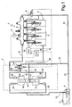
- Figure 1 is a diagram of an accumulation-volume fuel-injection system, according to a first embodiment of the invention;
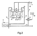
- Figure 2 represents a detail of another embodiment of the injection system of the invention;
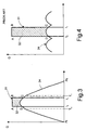
- Figure 3 represents a characteristic diagram of the operation of the injection system of Figure 1 and Figure 2; and
- Figure 4 represents a diagram of the operation of the injection system according to the known art.
- With reference to Figure 1, the
reference numeral 1 generically designates a fuel-injection system for an internal-combustion engine 2, for example a diesel engine. Theengine 2 comprises a plurality ofcylinders 3, for example four cylinders, which co-operate with corresponding pistons (not illustrated), actuatable for turning an engine shaft 4. - The
injection system 1 comprises a plurality of electrically controlled injectors 5, associated to thecylinders 3 and designed to perform a phase of injection of fuel therein at high pressure for injecting therein the fuel at high pressure. The injectors 5 are connected to an accumulation volume, which has a pre-determined volume for one or more injectors 5. The accumulation volume can also be distributed in thedelivery pipe 8 of the pump to the injectors. - In the embodiment illustrated in Figure 1, the accumulation volume is formed by a
common rail 6, to which all the injectors 5 are connected. Thecommon rail 6 is supplied with fuel at high pressure by a high-pressure pump, designated as a whole by 7, via a high-pressure delivery pipe 8. In turn, the high-pressure pump 7 is supplied by a low-pressure pump, for example anelectric pump 9, via aintake pipe 10 of the fuel at low pressure. - The
electric pump 9 is in general set in theusual fuel tank 11, into which there gives out apipe 12 for discharge of the fuel in excess of theinjection system 1. Thedischarge pipe 12 conveys towards thetank 11 both the fuel in excess discharged by the injectors 5 and the possible fuel in excess discharged by thecommon rail 6, when the pressure exceeds the one defined by aregulation solenoid valve 15. - Furthermore, for controlling the pressure of the fuel in the
common rail 6, between the high-pressure pump 7 and thetank 11, there is set at least one by-pass solenoid valve 14, which is designed to discharge into thetank 11, through thedischarge pipe 12, the possible fuel in excess with respect to what is necessary for maintaining the pressure required in thecommon rail 6. The by-pass solenoid valve 14 is obviously associated to anon-return valve 48 set on thedelivery pipe 8. - In the
tank 11, the fuel is at atmospheric pressure. In use, theelectric pump 9 compresses the fuel at low pressure, for example in the region of 2-3 bar. In turn, the high-pressure pump 7 compresses the fuel received from theintake pipe 10 so as to send the fuel at high pressure, for example in the region of 1600 bar, to thecommon rail 6, via thedelivery pipe 8. Each injector 5 is designed to be actuated for performing, in thecorresponding cylinder 3, a fuel injection of variable flow rate, i.e., with an amount of fuel that can vary between a minimum value and a maximum value under the control of anelectronic control unit 16, which may be formed by the usual microprocessor control unit for controlling theengine 2. - The
control unit 16 is designed to receive signals indicating the conditions of operation of theengine 2, such as the position of the accelerator pedal and the r.p.m. of the engine shaft 4, which are detected by corresponding sensors, as well as the pressure of the fuel in thecommon rail 6, detected by apressure sensor 17. By processing said received signals by means of an appropriate software, thecontrol unit 16 controls the instant and the duration of the actuation of the individual injectors 5, as well as theregulation solenoid valve 15. - The high-
pressure pump 7 comprises one ormore pumping elements 18 of the reciprocating-motion type, each formed by acylinder 19 having acompression chamber 20, in which there slides apiston 21. Thecompression chamber 20 is in communication with theintake pipe 10, via aintake valve 25, and is in communication with thedelivery pipe 8, via adelivery valve 30. Thepiston 21 is actuated bycam means 22 carried by ashaft 23, with a sinusoidal reciprocating motion comprising a suction stroke and a compression or delivery stroke, as will be more clearly seen hereinafter. - In the example illustrated in Figure 1, the
shaft 23 of thepump 7 is connected to the engine shaft 4 via a device for transmission ofmotion 26, such as to control a compression stroke for each injection of the injectors 5 into therespective cylinders 3. Consequently, in the four-stroke engine 2, the speed of rotation of theshaft 23 of thepump 7 is equal to one half of the speed of rotation of the engine (transmission ratio = 0.5). Theshaft 23 may be represented by a shaft provided for actuating other devices of the engine. - Advantageously, in the case of a four-stroke engine, the
shaft 23 may be represented by the usual camshaft for control of the intake and exhaust valves of thecylinders 3 of theengine 2. In engines with four or more cylinders, thepump 7 is equipped in general with a number ofpumping elements 18, which can be actuated by a common cam. In particular, in the embodiment of Figure 1, thepump 7 is equipped with twopumping elements 18 arranged diametrically opposite to one another and actuated by acommon cam 22. - In the diagram of Figure 3, the compression stroke of each
pumping element 18 is indicated on the abscissa by the segment between a bottom dead centre Pi and a top dead centre Ps. The speed of thepumping element 18 is represented by asinusoidal curve 24, which consequently represents also the instantaneous flow rate of thepumping element 18 in the absence of the by-pass solenoid valve 14. Consequently, the area under thecurve 24 represents the maximum volume of fuel delivered in one pumping stroke. The actuation of an injector 5 for each injection phase in therespective cylinder 3 is represented by arectangle 31, i.e., IoABI1, the base of which on the abscissa is a segment between a starting point Io and an end point I1, whilst the height indicates the instantaneous flow rate (herein assumed as being constant) of the injector 5. The area of the rectangle IoABI1 thus represents the volume of fuel delivered by the injector 5 in its injection phase. Said volume varies both as regards the duration, by varying the position of the points Io and I1 and as regards the flow rate, by varying the instantaneous flow rate of the injector, i.e., the height of therectangle 31, for example by varying the pressure of the fuel in thecommon rail 6. - In the known art, represented by the diagram of Figure 4, the volume of fuel IoCDI1 introduced by the pump during the injection event, of a
pumping element 1 is only a fraction of the maximum flow rate of the injector 5, for example only in the region of 20%; so that, under full load of theengine 2, the remaining part ABCD, i.e., 80% of the volume of fuel to be injected, must be supplied by thecommon rail 6. Therail 6 must thus have a considerable volume so that the pressure of the fuel contained therein does not oscillate too much during each injection event. Furthermore, 80% of the fuel must be supplied by other deliveries of thepumping elements 18, for example by means of a pump with threepumping elements 18, as illustrated in Figure 4, where thepumping elements 18 work constantly at maximum delivery. - According to the invention, the
pumping element 18 has an instantaneous flow rate, the maximum value of which is of the same order of magnitude as the maximum flow rate of each injector 5, as indicated in Figure 3. In particular, the instantaneous maximum flow rate of thepumping element 18 is equal to at least 50% of the maximum flow rate of the injector 5. Advantageously, the instantaneous maximum flow rate of thepumping element 18 may be chosen between 70% and 90% of the maximum flow rate of the injector 5. The compression stroke Pi-Ps of thepumping element 18 occurs in synchronism with the injection phase of the injector 5. In turn, the by-pass solenoid valve 14 is controlled by thecontrol unit 16 in a chopped way, through achopper unit 28. Advantageously, thechopper unit 28 is integrated with thecontrol unit 16 and is thus implemented with a corresponding software, but in the drawings it is represented separately for reasons of clarity of description. - The
control unit 16 via thechopper unit 28 is designed to control thesolenoid valve 14 by means of a PWM logic signal, and at a frequency correlated to the speed of thepump 7. Consequently, the delivery of thepump 7 is carried out only during a part of the compression stroke of theindividual pumping element 18 when the by-pass solenoid valve 14 is intercepted or closed. Instead, in the remaining part of the compression stroke, since the by-pass valve 14 is open, thecompression chamber 20 is in communication with thetank 11, so that thepump 7 presents a low dissipation of energy. The angle of effective delivery of each pumpingelement 18 is chosen according to the conditions of operation of theengine 2, i.e., according to the flow rate required by the injectors 5. - In particular, the
control unit 16, via thechopper unit 28, is designed for modulating the delivery of thepumping elements 18 in a chopped way, controlling opening of thesolenoid valve 14 between an instant To of start of delivery during compression and an instant T1 of end of delivery, so as to supply to thedelivery pipe 8 the majority (area I0DCI1 in Figure 3) of the fuel to be injected in the simultaneous injection of the corresponding injector 5. In this way, thecommon rail 6 must supply just one minimum amount of fuel (area DABC in Figure 3), so that the pressure therein is maintained constant even though the accumulation volume of therail 6 is reduced. - In particular, the instants To and T1 correspond to two intermediate points of the compression stroke of the
pumping element 18. Thecontrol unit 16, via thechopper unit 28, modulates or varies both the instant of start To of delivery and the instant of end T1 of delivery. Advantageously, to reduce the displacement of thepump 7, the delivery is symmetrical or barycentric both with respect to the compression stroke Pi-Ps of thepumping element 18 and with respect to the injection phase Io-I1. In this way, thecommon rail 6 may be designed with very small dimensions or may even coincide with the volume of the high-pressure pipe 8 itself, given that the fuel injected thereby is simultaneously reintegrated according to a diagram equivalent to the diagram of the injection phase. - According to the embodiment of Figure 2, the two
pumping elements 18 are arranged in line and are actuated by twodifferent cams 22 fixed on theshaft 23 in diametrically opposite positions. The by-pass solenoid valve 14 is also here set on thedelivery pipe 8, being associated to a correspondingnon-return valve 48. - It is evident that the injection system described above provides a method for controlling the pressure of the fuel in the
accumulation volume 6, into which the fuel is supplied by at least onepumping element 18, which moves with reciprocating motion including a compression stroke, through adelivery pipe 8 equipped with a by-pass solenoid valve 14, the method of control being characterized by the following steps: - provision of a
pumping element 18 with an instantaneous maximum flow rate of the same order of magnitude as the maximum flow rate of an injection phase of each injector 5; - provision of a by-
pass solenoid valve 14 on adelivery pipe 8 of said pumpingelement 18; - actuation of the
pumping element 18 in synchronism with said injection phase; and - control of said by-
pass solenoid valve 14 for modulating the delivery by varying both its instant of starting To and its instant of end T1, in such a way that said delivery is barycentric with respect to said compression stroke Pi-Ps. - In this way, the amount of fuel supplied by the common rail to each injector 5 for each injection phase is reduced to the minimum.
- From what has been seen above, the advantages of the injection system according to the invention as compared to the known systems are evident. In particular, since the flow rate of the
pumping element 18 is of the same order of magnitude as the maximum flow rate of an injection phase of the injector 5, the fuel supplied by thecommon rail 6 for injection is normally altogether negligible and is small also when the injector 5 operates at its maximum flow rate. Furthermore, since delivery is carried out simultaneously with injection and is barycentric both with respect to the injection phase and with respect to the compression stroke of thepumping element 18, thecommon rail 6 can have very small dimensions or be eliminated altogether, with beneficial effects on the layout of the injection system in the engine compartment. - It is understood that various other modifications and improvements may be made to the injection system described herein, without thereby departing from the scope of the claims. For example, the by-
pass solenoid valve 14 may be integrated with thepump 7. Furthermore, each pumpingelement 18 of thepump 7 may be equipped with a by-pass solenoid valve of its own on the corresponding delivery pipe. The high-pressure pump 7 may be constituted by a pump with three or more radial pumping elements, used also in engines with a number of cylinders different from four. Finally, thepump 7 can also be constituted by just onepumping element 18.
Claims (11)
- An accumulation volume fuel-injection system for an internal-combustion engine having at least one cylinder (3), comprising a pump (7) designed to send fuel at high pressure to an accumulation volume (6), at least one injector (5) supplied by said accumulation volume (6) and actuatable for performing a phase of injection of pressurized fuel into said cylinder (3), said pump (7) comprising at least one reciprocating-motion pumping element (18) with a compression stroke (Pi-Ps) in synchronism with said injection phase, and a by-pass solenoid valve (14) for the fuel sent by said pump (7) into the accumulation volume (6); said system being characterized in that said pumping element (18) has an instantaneous maximum flow rate of the same order of magnitude as the maximum flow rate of said injector (5), said by-pass solenoid valve (14) being controlled by a chopper control unit (16, 28) in synchronism with said compression stroke (Pi-Ps).
- The injection system according to Claim 1, characterized in that said by-pass solenoid valve (14) is controlled by said chopper control unit (16, 28), via pulse-width modulation (PWM), with a pulse having an instant of start (To) of delivery and an instant of end (T1) of the delivery during said compression stroke (Pi-Ps), according to the operating conditions of the engine (2), said modulation being obtained by varying both said instant of start (To) and said instant of end (T1).
- The injection system according to Claim 2, characterized in that said delivery is simultaneous with said injection phase and is barycentric with respect to said compression stroke (Pi-Ps).
- The injection system according to any one of the preceding claims, characterized in that the instantaneous maximum flow rate of said pumping element (18) is equal to at least 50% of the maximum flow rate of said injector (5).
- The injection system according to Claim 4, characterized in that the instantaneous maximum flow rate of said pumping element (18) is comprised between 70% and 90% of the maximum flow rate of said injector (5).
- The injection system according to any one of the preceding claims, characterized in that said pump (7) comprises at least two pumping elements (18), each having a compression chamber (20) in communication with said accumulation volume (6) by means of a delivery pipe (8), said by-pass solenoid valve (14) being set on said delivery pipe (8).
- The injection system according to Claim 6, characterized in that said pumping elements (18) are coaxial and set opposite to one another and are actuated by a common cam (22).
- The injection system according to Claim 7, characterized in that said pumping elements (18) are parallel to one another and are actuated by two corresponding coaxial cams (22).
- A high-pressure pump for sending fuel to an accumulation volume (6) designed to supply at least one fuel injector (5), said pump (7) comprising at least one reciprocating-motion pumping element (18) with a compression stroke (Pi-Ps), said pumping element (18) having a compression chamber (20) in communication with a delivery pipe (8), and a by-pass solenoid valve (14) set on said delivery pipe (8) for controlling the amount of fuel sent by said pump (7) into the accumulation volume (6); said pump being characterized in that said by-pass solenoid valve (14) is controlled in such a way that said delivery is barycentric with respect to said compression stroke (Pi-Ps).
- The high-pressure pump according to Claim 9, characterized in that said by-pass solenoid valve (14) is controlled by pulse-width modulation (PWM) having an instant of start (To) and an instant of end (T1) of delivery, said modulation being obtained by varying both said instant of start (To) and said instant of end (T1), said delivery being controlled in synchronism with said injection phase.
- A method for controlling the pressure of the fuel in an accumulation volume (6) for at least one fuel injector (5) in an internal-combustion engine (2), in which the fuel is supplied to the accumulation volume (6) by at least one pumping element (18), which moves with reciprocating motion including a compression stroke (Pi-Ps), said method being characterized by the following steps:- provision of a pumping element (18) with an instantaneous maximum flow rate of the same order of magnitude as the maximum flow rate of said injector (5);- provision of a by-pass solenoid valve (14) on a delivery pipe (8) of said pumping element (18);- actuation of said pumping element (18) in synchronism with each of said injection phases; and- control of said by-pass solenoid valve (14) for modulating the delivery by varying both its instant of start (To) and its instant of end (T1) in such a way that said delivery is barycentric with respect to said compression stroke (Pi-Ps).
Priority Applications (6)
| Application Number | Priority Date | Filing Date | Title |
|---|---|---|---|
| AT04425839T ATE394592T1 (en) | 2004-11-12 | 2004-11-12 | A BATTERY VOLUME FUEL INJECTION SYSTEM FOR AN INTERNAL COMBUSTION ENGINE |
| DE602004013602T DE602004013602D1 (en) | 2004-11-12 | 2004-11-12 | A fuel injection system with accumulator volume for an internal combustion engine |
| EP04425839A EP1657430B1 (en) | 2004-11-12 | 2004-11-12 | An accumulation volume fuel injection system for an internal combustion engine |
| US11/113,502 US7444988B2 (en) | 2004-11-12 | 2005-04-25 | Accumulation-volume fuel injection system for an internal-combustion engine |
| JP2005132726A JP4284299B2 (en) | 2004-11-12 | 2005-04-28 | Accumulation chamber type fuel injection system for internal combustion engine |
| US12/261,650 US7980223B2 (en) | 2004-11-12 | 2008-10-30 | Accumulation-volume fuel injection system for an internal-combustion engine |
Applications Claiming Priority (1)
| Application Number | Priority Date | Filing Date | Title |
|---|---|---|---|
| EP04425839A EP1657430B1 (en) | 2004-11-12 | 2004-11-12 | An accumulation volume fuel injection system for an internal combustion engine |
Publications (2)
| Publication Number | Publication Date |
|---|---|
| EP1657430A1 true EP1657430A1 (en) | 2006-05-17 |
| EP1657430B1 EP1657430B1 (en) | 2008-05-07 |
Family
ID=34932878
Family Applications (1)
| Application Number | Title | Priority Date | Filing Date |
|---|---|---|---|
| EP04425839A Expired - Lifetime EP1657430B1 (en) | 2004-11-12 | 2004-11-12 | An accumulation volume fuel injection system for an internal combustion engine |
Country Status (5)
| Country | Link |
|---|---|
| US (2) | US7444988B2 (en) |
| EP (1) | EP1657430B1 (en) |
| JP (1) | JP4284299B2 (en) |
| AT (1) | ATE394592T1 (en) |
| DE (1) | DE602004013602D1 (en) |
Cited By (1)
| Publication number | Priority date | Publication date | Assignee | Title |
|---|---|---|---|---|
| CN101988436A (en) * | 2009-07-31 | 2011-03-23 | 福特环球技术公司 | Methods for operating a fuel system |
Families Citing this family (7)
| Publication number | Priority date | Publication date | Assignee | Title |
|---|---|---|---|---|
| ATE394592T1 (en) * | 2004-11-12 | 2008-05-15 | Fiat Ricerche | A BATTERY VOLUME FUEL INJECTION SYSTEM FOR AN INTERNAL COMBUSTION ENGINE |
| DE102006027486A1 (en) * | 2006-06-14 | 2007-12-20 | Robert Bosch Gmbh | Fuel injection device for an internal combustion engine |
| ATE457423T1 (en) * | 2007-09-11 | 2010-02-15 | Fiat Ricerche | FUEL INJECTION DEVICE WITH A VARIABLE FLOW HIGH PRESSURE FUEL PUMP |
| US9753443B2 (en) | 2014-04-21 | 2017-09-05 | Synerject Llc | Solenoid systems and methods for detecting length of travel |
| US9997287B2 (en) | 2014-06-06 | 2018-06-12 | Synerject Llc | Electromagnetic solenoids having controlled reluctance |
| WO2015191348A1 (en) | 2014-06-09 | 2015-12-17 | Synerject Llc | Methods and apparatus for cooling a solenoid coil of a solenoid pump |
| DE102016204408A1 (en) * | 2016-03-17 | 2017-09-21 | Robert Bosch Gmbh | Method for determining a setpoint for a manipulated variable for controlling a low-pressure pump |
Citations (4)
| Publication number | Priority date | Publication date | Assignee | Title |
|---|---|---|---|---|
| EP0507191A1 (en) * | 1991-04-04 | 1992-10-07 | Toyota Jidosha Kabushiki Kaisha | A fuel injection device of an engine |
| US6135090A (en) * | 1998-01-07 | 2000-10-24 | Unisia Jecs Corporation | Fuel injection control system |
| EP1273797A2 (en) * | 2001-07-05 | 2003-01-08 | Robert Bosch Gmbh | Fuel injection device |
| WO2003016705A1 (en) * | 2001-08-17 | 2003-02-27 | Volvo Teknisk Utveckling Ab | Method of controlling the injection of fuel into a combustion chamber and a fuel injection device for performing said method |
Family Cites Families (17)
| Publication number | Priority date | Publication date | Assignee | Title |
|---|---|---|---|---|
| US5345916A (en) * | 1993-02-25 | 1994-09-13 | General Motors Corporation | Controlled fuel injection rate for optimizing diesel engine operation |
| US6694950B2 (en) * | 1999-02-17 | 2004-02-24 | Stanadyne Corporation | Hybrid control method for fuel pump using intermittent recirculation at low and high engine speeds |
| IT1319633B1 (en) * | 2000-01-18 | 2003-10-20 | Fiat Ricerche | METHOD OF ASSESSMENT OF THE FUNCTIONALITY OF A COMMON MANIFOLD INJECTION SYSTEM OF AN INTERNAL COMBUSTION ENGINE. |
| JP3685317B2 (en) * | 2000-02-18 | 2005-08-17 | 株式会社デンソー | Fuel injection pump |
| JP3842002B2 (en) * | 2000-03-01 | 2006-11-08 | 三菱電機株式会社 | Variable discharge fuel supply system |
| DE10017060B4 (en) * | 2000-04-05 | 2005-05-19 | Daimlerchrysler Ag | Method for operating a diesel internal combustion engine with a pump-line-nozzle injection system |
| DE10039773A1 (en) * | 2000-08-16 | 2002-02-28 | Bosch Gmbh Robert | Fuel supply system |
| IT1320684B1 (en) * | 2000-10-03 | 2003-12-10 | Fiat Ricerche | FLOW RATE CONTROL DEVICE OF A HIGH PRESSURE PUMP IN A COMMON COLLECTOR INJECTION SYSTEM OF A FUEL |
| DE10057786A1 (en) * | 2000-11-22 | 2002-06-06 | Siemens Ag | Injection system for an internal combustion engine and method for regulating and / or venting such an injection system |
| ITTO20001228A1 (en) * | 2000-12-29 | 2002-06-29 | Fiat Ricerche | FUEL INJECTION SYSTEM FOR AN INTERNAL COMBUSTION ENGINE. |
| DE10215021A1 (en) * | 2002-04-05 | 2003-10-23 | Bosch Gmbh Robert | Fuel injection device for an internal combustion engine |
| ITTO20020619A1 (en) * | 2002-07-16 | 2004-01-16 | Fiat Ricerche | METHOD OF CHECKING THE FUEL INJECTION PRESSURE OF A COMMON MANIFOLD INJECTION SYSTEM OF A COMBUSTION ENGINE |
| ATE507384T1 (en) * | 2004-06-30 | 2011-05-15 | Fiat Ricerche | FUEL INJECTION SYSTEM FOR INTERNAL COMBUSTION ENGINE WITH COMMON RAIL |
| ATE394592T1 (en) * | 2004-11-12 | 2008-05-15 | Fiat Ricerche | A BATTERY VOLUME FUEL INJECTION SYSTEM FOR AN INTERNAL COMBUSTION ENGINE |
| EP1674718B1 (en) * | 2004-12-23 | 2007-03-14 | C.R.F. Società Consortile per Azioni | Internal combustion engine storage-volume fuel injection system |
| EP1865193B1 (en) * | 2006-06-09 | 2010-11-03 | C.R.F. Società Consortile per Azioni | Fuel injection system for an internal combustion engine |
| ATE457423T1 (en) * | 2007-09-11 | 2010-02-15 | Fiat Ricerche | FUEL INJECTION DEVICE WITH A VARIABLE FLOW HIGH PRESSURE FUEL PUMP |
-
2004
- 2004-11-12 AT AT04425839T patent/ATE394592T1/en not_active IP Right Cessation
- 2004-11-12 EP EP04425839A patent/EP1657430B1/en not_active Expired - Lifetime
- 2004-11-12 DE DE602004013602T patent/DE602004013602D1/en not_active Expired - Lifetime
-
2005
- 2005-04-25 US US11/113,502 patent/US7444988B2/en not_active Expired - Lifetime
- 2005-04-28 JP JP2005132726A patent/JP4284299B2/en not_active Expired - Lifetime
-
2008
- 2008-10-30 US US12/261,650 patent/US7980223B2/en not_active Expired - Lifetime
Patent Citations (4)
| Publication number | Priority date | Publication date | Assignee | Title |
|---|---|---|---|---|
| EP0507191A1 (en) * | 1991-04-04 | 1992-10-07 | Toyota Jidosha Kabushiki Kaisha | A fuel injection device of an engine |
| US6135090A (en) * | 1998-01-07 | 2000-10-24 | Unisia Jecs Corporation | Fuel injection control system |
| EP1273797A2 (en) * | 2001-07-05 | 2003-01-08 | Robert Bosch Gmbh | Fuel injection device |
| WO2003016705A1 (en) * | 2001-08-17 | 2003-02-27 | Volvo Teknisk Utveckling Ab | Method of controlling the injection of fuel into a combustion chamber and a fuel injection device for performing said method |
Cited By (2)
| Publication number | Priority date | Publication date | Assignee | Title |
|---|---|---|---|---|
| CN101988436A (en) * | 2009-07-31 | 2011-03-23 | 福特环球技术公司 | Methods for operating a fuel system |
| CN101988436B (en) * | 2009-07-31 | 2015-07-01 | 福特环球技术公司 | Methods for operating a fuel system |
Also Published As
| Publication number | Publication date |
|---|---|
| US20090050110A1 (en) | 2009-02-26 |
| JP2006138312A (en) | 2006-06-01 |
| US7980223B2 (en) | 2011-07-19 |
| DE602004013602D1 (en) | 2008-06-19 |
| US7444988B2 (en) | 2008-11-04 |
| EP1657430B1 (en) | 2008-05-07 |
| ATE394592T1 (en) | 2008-05-15 |
| JP4284299B2 (en) | 2009-06-24 |
| US20060102151A1 (en) | 2006-05-18 |
Similar Documents
| Publication | Publication Date | Title |
|---|---|---|
| US7980223B2 (en) | Accumulation-volume fuel injection system for an internal-combustion engine | |
| EP1612394B1 (en) | Fuel injection system for an internal combustion engine with common rail | |
| EP1533516B1 (en) | Control device of high-pressure fuel pump of internal combustion engine | |
| JP3170381U (en) | High pressure flow variable pump for fuel injection system | |
| KR100367189B1 (en) | Fuel supplying apparatus and method for internal combustion engine | |
| US6135090A (en) | Fuel injection control system | |
| KR970704960A (en) | Fuel injection control device in cylinder internal combustion internal combustion engine | |
| US6976473B2 (en) | Fuel injection system for an internal combustion engine | |
| EP1674718B1 (en) | Internal combustion engine storage-volume fuel injection system | |
| US6467461B1 (en) | Fuel control of direct-injection internal combustion engine of a motor vehicle, in particular in start operation | |
| EP1657434B1 (en) | A high-pressure pump with a device for regulating the flow rate for a fuel-injection system | |
| KR101980363B1 (en) | Common rail injection system for an internal combustion engine | |
| JPH09222056A (en) | Fuel injection device | |
| JP4329755B2 (en) | High pressure fuel pump for internal combustion engine | |
| EP1873382B1 (en) | Control device of high-pressure fuel pump of internal combustion engine | |
| JP2007071140A (en) | Fuel supply device for internal combustion engine |
Legal Events
| Date | Code | Title | Description |
|---|---|---|---|
| PUAI | Public reference made under article 153(3) epc to a published international application that has entered the european phase |
Free format text: ORIGINAL CODE: 0009012 |
|
| AK | Designated contracting states |
Kind code of ref document: A1 Designated state(s): AT BE BG CH CY CZ DE DK EE ES FI FR GB GR HU IE IS IT LI LU MC NL PL PT RO SE SI SK TR |
|
| AX | Request for extension of the european patent |
Extension state: AL HR LT LV MK YU |
|
| 17P | Request for examination filed |
Effective date: 20060519 |
|
| 17Q | First examination report despatched |
Effective date: 20061228 |
|
| AKX | Designation fees paid |
Designated state(s): AT BE BG CH CY CZ DE DK EE ES FI FR GB GR HU IE IS IT LI LU MC NL PL PT RO SE SI SK TR |
|
| GRAP | Despatch of communication of intention to grant a patent |
Free format text: ORIGINAL CODE: EPIDOSNIGR1 |
|
| GRAS | Grant fee paid |
Free format text: ORIGINAL CODE: EPIDOSNIGR3 |
|
| GRAA | (expected) grant |
Free format text: ORIGINAL CODE: 0009210 |
|
| RIN1 | Information on inventor provided before grant (corrected) |
Inventor name: RICCO, RAFFAELEC/O C.R.F. SOCIETA CONSORTILE Inventor name: DE MATTHAEIS, SISTO LUIGIC/O C.R.F. SOCIETA Inventor name: RICCO, MARIOC/O C.R.F. SOCIETA CONSORTILE PER Inventor name: LEPORE, DOMENICOC/O C.R.F. SOCIETA CONSORTILE PER |
|
| AK | Designated contracting states |
Kind code of ref document: B1 Designated state(s): AT BE BG CH CY CZ DE DK EE ES FI FR GB GR HU IE IS IT LI LU MC NL PL PT RO SE SI SK TR |
|
| REG | Reference to a national code |
Ref country code: GB Ref legal event code: FG4D |
|
| REG | Reference to a national code |
Ref country code: CH Ref legal event code: EP |
|
| REG | Reference to a national code |
Ref country code: IE Ref legal event code: FG4D Free format text: LANGUAGE OF EP DOCUMENT: FRENCH |
|
| REF | Corresponds to: |
Ref document number: 602004013602 Country of ref document: DE Date of ref document: 20080619 Kind code of ref document: P |
|
| PG25 | Lapsed in a contracting state [announced via postgrant information from national office to epo] |
Ref country code: SI Free format text: LAPSE BECAUSE OF FAILURE TO SUBMIT A TRANSLATION OF THE DESCRIPTION OR TO PAY THE FEE WITHIN THE PRESCRIBED TIME-LIMIT Effective date: 20080507 |
|
| PG25 | Lapsed in a contracting state [announced via postgrant information from national office to epo] |
Ref country code: FI Free format text: LAPSE BECAUSE OF FAILURE TO SUBMIT A TRANSLATION OF THE DESCRIPTION OR TO PAY THE FEE WITHIN THE PRESCRIBED TIME-LIMIT Effective date: 20080507 Ref country code: ES Free format text: LAPSE BECAUSE OF FAILURE TO SUBMIT A TRANSLATION OF THE DESCRIPTION OR TO PAY THE FEE WITHIN THE PRESCRIBED TIME-LIMIT Effective date: 20080818 Ref country code: NL Free format text: LAPSE BECAUSE OF FAILURE TO SUBMIT A TRANSLATION OF THE DESCRIPTION OR TO PAY THE FEE WITHIN THE PRESCRIBED TIME-LIMIT Effective date: 20080507 |
|
| NLV1 | Nl: lapsed or annulled due to failure to fulfill the requirements of art. 29p and 29m of the patents act | ||
| PG25 | Lapsed in a contracting state [announced via postgrant information from national office to epo] |
Ref country code: AT Free format text: LAPSE BECAUSE OF FAILURE TO SUBMIT A TRANSLATION OF THE DESCRIPTION OR TO PAY THE FEE WITHIN THE PRESCRIBED TIME-LIMIT Effective date: 20080507 Ref country code: PL Free format text: LAPSE BECAUSE OF FAILURE TO SUBMIT A TRANSLATION OF THE DESCRIPTION OR TO PAY THE FEE WITHIN THE PRESCRIBED TIME-LIMIT Effective date: 20080507 |
|
| PG25 | Lapsed in a contracting state [announced via postgrant information from national office to epo] |
Ref country code: IS Free format text: LAPSE BECAUSE OF FAILURE TO SUBMIT A TRANSLATION OF THE DESCRIPTION OR TO PAY THE FEE WITHIN THE PRESCRIBED TIME-LIMIT Effective date: 20080907 |
|
| PG25 | Lapsed in a contracting state [announced via postgrant information from national office to epo] |
Ref country code: PT Free format text: LAPSE BECAUSE OF FAILURE TO SUBMIT A TRANSLATION OF THE DESCRIPTION OR TO PAY THE FEE WITHIN THE PRESCRIBED TIME-LIMIT Effective date: 20081007 Ref country code: DK Free format text: LAPSE BECAUSE OF FAILURE TO SUBMIT A TRANSLATION OF THE DESCRIPTION OR TO PAY THE FEE WITHIN THE PRESCRIBED TIME-LIMIT Effective date: 20080507 Ref country code: SE Free format text: LAPSE BECAUSE OF FAILURE TO SUBMIT A TRANSLATION OF THE DESCRIPTION OR TO PAY THE FEE WITHIN THE PRESCRIBED TIME-LIMIT Effective date: 20080807 Ref country code: CZ Free format text: LAPSE BECAUSE OF FAILURE TO SUBMIT A TRANSLATION OF THE DESCRIPTION OR TO PAY THE FEE WITHIN THE PRESCRIBED TIME-LIMIT Effective date: 20080507 |
|
| PG25 | Lapsed in a contracting state [announced via postgrant information from national office to epo] |
Ref country code: SK Free format text: LAPSE BECAUSE OF FAILURE TO SUBMIT A TRANSLATION OF THE DESCRIPTION OR TO PAY THE FEE WITHIN THE PRESCRIBED TIME-LIMIT Effective date: 20080507 Ref country code: RO Free format text: LAPSE BECAUSE OF FAILURE TO SUBMIT A TRANSLATION OF THE DESCRIPTION OR TO PAY THE FEE WITHIN THE PRESCRIBED TIME-LIMIT Effective date: 20080507 Ref country code: BE Free format text: LAPSE BECAUSE OF FAILURE TO SUBMIT A TRANSLATION OF THE DESCRIPTION OR TO PAY THE FEE WITHIN THE PRESCRIBED TIME-LIMIT Effective date: 20080507 |
|
| PLBE | No opposition filed within time limit |
Free format text: ORIGINAL CODE: 0009261 |
|
| STAA | Information on the status of an ep patent application or granted ep patent |
Free format text: STATUS: NO OPPOSITION FILED WITHIN TIME LIMIT |
|
| 26N | No opposition filed |
Effective date: 20090210 |
|
| PG25 | Lapsed in a contracting state [announced via postgrant information from national office to epo] |
Ref country code: EE Free format text: LAPSE BECAUSE OF FAILURE TO SUBMIT A TRANSLATION OF THE DESCRIPTION OR TO PAY THE FEE WITHIN THE PRESCRIBED TIME-LIMIT Effective date: 20080507 Ref country code: BG Free format text: LAPSE BECAUSE OF FAILURE TO SUBMIT A TRANSLATION OF THE DESCRIPTION OR TO PAY THE FEE WITHIN THE PRESCRIBED TIME-LIMIT Effective date: 20080807 |
|
| PG25 | Lapsed in a contracting state [announced via postgrant information from national office to epo] |
Ref country code: MC Free format text: LAPSE BECAUSE OF NON-PAYMENT OF DUE FEES Effective date: 20081130 |
|
| REG | Reference to a national code |
Ref country code: CH Ref legal event code: PL |
|
| GBPC | Gb: european patent ceased through non-payment of renewal fee |
Effective date: 20081112 |
|
| REG | Reference to a national code |
Ref country code: IE Ref legal event code: MM4A |
|
| PG25 | Lapsed in a contracting state [announced via postgrant information from national office to epo] |
Ref country code: CH Free format text: LAPSE BECAUSE OF NON-PAYMENT OF DUE FEES Effective date: 20081130 Ref country code: IE Free format text: LAPSE BECAUSE OF NON-PAYMENT OF DUE FEES Effective date: 20081112 Ref country code: LI Free format text: LAPSE BECAUSE OF NON-PAYMENT OF DUE FEES Effective date: 20081130 |
|
| PG25 | Lapsed in a contracting state [announced via postgrant information from national office to epo] |
Ref country code: GB Free format text: LAPSE BECAUSE OF NON-PAYMENT OF DUE FEES Effective date: 20081112 |
|
| PG25 | Lapsed in a contracting state [announced via postgrant information from national office to epo] |
Ref country code: HU Free format text: LAPSE BECAUSE OF FAILURE TO SUBMIT A TRANSLATION OF THE DESCRIPTION OR TO PAY THE FEE WITHIN THE PRESCRIBED TIME-LIMIT Effective date: 20081108 Ref country code: CY Free format text: LAPSE BECAUSE OF FAILURE TO SUBMIT A TRANSLATION OF THE DESCRIPTION OR TO PAY THE FEE WITHIN THE PRESCRIBED TIME-LIMIT Effective date: 20080507 Ref country code: LU Free format text: LAPSE BECAUSE OF NON-PAYMENT OF DUE FEES Effective date: 20081112 |
|
| PG25 | Lapsed in a contracting state [announced via postgrant information from national office to epo] |
Ref country code: TR Free format text: LAPSE BECAUSE OF FAILURE TO SUBMIT A TRANSLATION OF THE DESCRIPTION OR TO PAY THE FEE WITHIN THE PRESCRIBED TIME-LIMIT Effective date: 20080507 |
|
| PG25 | Lapsed in a contracting state [announced via postgrant information from national office to epo] |
Ref country code: GR Free format text: LAPSE BECAUSE OF FAILURE TO SUBMIT A TRANSLATION OF THE DESCRIPTION OR TO PAY THE FEE WITHIN THE PRESCRIBED TIME-LIMIT Effective date: 20080808 |
|
| REG | Reference to a national code |
Ref country code: DE Ref legal event code: R082 Ref document number: 602004013602 Country of ref document: DE Representative=s name: KOTITSCHKE & HEURUNG PARTNERSCHAFT MBB PATENT-, DE Ref country code: DE Ref legal event code: R082 Ref document number: 602004013602 Country of ref document: DE Representative=s name: KOTITSCHKE & HEURUNG PARTNERSCHAFT MBB, DE Ref country code: DE Ref legal event code: R082 Ref document number: 602004013602 Country of ref document: DE Representative=s name: DR. RALF KOTITSCHKE, DE |
|
| REG | Reference to a national code |
Ref country code: FR Ref legal event code: PLFP Year of fee payment: 12 |
|
| REG | Reference to a national code |
Ref country code: FR Ref legal event code: PLFP Year of fee payment: 13 |
|
| REG | Reference to a national code |
Ref country code: FR Ref legal event code: PLFP Year of fee payment: 14 |
|
| PGFP | Annual fee paid to national office [announced via postgrant information from national office to epo] |
Ref country code: IT Payment date: 20231019 Year of fee payment: 20 Ref country code: DE Payment date: 20231019 Year of fee payment: 20 Ref country code: FR Payment date: 20231019 Year of fee payment: 20 |
|
| REG | Reference to a national code |
Ref country code: DE Ref legal event code: R071 Ref document number: 602004013602 Country of ref document: DE |