EP1657322A2 - Plasma spray apparatus - Google Patents
Plasma spray apparatus Download PDFInfo
- Publication number
- EP1657322A2 EP1657322A2 EP05256848A EP05256848A EP1657322A2 EP 1657322 A2 EP1657322 A2 EP 1657322A2 EP 05256848 A EP05256848 A EP 05256848A EP 05256848 A EP05256848 A EP 05256848A EP 1657322 A2 EP1657322 A2 EP 1657322A2
- Authority
- EP
- European Patent Office
- Prior art keywords
- plasma
- spray apparatus
- plasma spray
- gas
- anode
- Prior art date
- Legal status (The legal status is an assumption and is not a legal conclusion. Google has not performed a legal analysis and makes no representation as to the accuracy of the status listed.)
- Granted
Links
Images


Classifications
-
- B—PERFORMING OPERATIONS; TRANSPORTING
- B05—SPRAYING OR ATOMISING IN GENERAL; APPLYING FLUENT MATERIALS TO SURFACES, IN GENERAL
- B05B—SPRAYING APPARATUS; ATOMISING APPARATUS; NOZZLES
- B05B7/00—Spraying apparatus for discharge of liquids or other fluent materials from two or more sources, e.g. of liquid and air, of powder and gas
- B05B7/16—Spraying apparatus for discharge of liquids or other fluent materials from two or more sources, e.g. of liquid and air, of powder and gas incorporating means for heating or cooling the material to be sprayed
- B05B7/22—Spraying apparatus for discharge of liquids or other fluent materials from two or more sources, e.g. of liquid and air, of powder and gas incorporating means for heating or cooling the material to be sprayed electrically, magnetically or electromagnetically, e.g. by arc
- B05B7/222—Spraying apparatus for discharge of liquids or other fluent materials from two or more sources, e.g. of liquid and air, of powder and gas incorporating means for heating or cooling the material to be sprayed electrically, magnetically or electromagnetically, e.g. by arc using an arc
- B05B7/226—Spraying apparatus for discharge of liquids or other fluent materials from two or more sources, e.g. of liquid and air, of powder and gas incorporating means for heating or cooling the material to be sprayed electrically, magnetically or electromagnetically, e.g. by arc using an arc the material being originally a particulate material
Definitions
- the present disclosure generally relates to a plasma spray coating apparatus, such as a microplasma spray coating apparatus, for spray coating a workpiece and a method for using the same.
- Plasma coating methods and apparatus are known. For example, one such method and apparatus for plasma flame spray coating material onto a substrate by means of passing a plasma forming gas through a nozzle electrode, and passing an arc forming current between the nozzle electrode and a rear electrode to form a plasma effluent.
- the method includes introducing coating material into the plasma effluent, passing the plasma effluent axially through a wall shroud extending from the exit of said nozzle electrode, and forming a flame shroud for the plasma effluent. The coating is thereby applied to the substrate.
- the blade roots of compressor blades can be coated with material to meet dimensional tolerance requirements for sealing the compressor blade with the compressor wheel and the like.
- Metallic coatings consisting of copper-nickel, aluminum-copper, and other similar composition materials have been applied in this regard using various conventional plasma spray coating processes.
- the coating process requires the workpiece to be masked in areas where the material transfer is not required and/or not desired.
- the workpiece is typically coated in a dedicated facility such as a gas turbine engine manufacturing plant or repair shop.
- a plasma spray apparatus for coating at least a portion of a workpiece such as a gas turbine compressor blade.
- a plasma apparatus includes an anode, cathode, and an arc generator for generating an electric arc between the anode and cathode.
- the apparatus includes an arc gas emitter for injecting gas into the electric arc.
- the electric arc is operable for ionizing the gas to create a plasma gas stream.
- a powder feeder provides powdered material to the plasma apparatus.
- a powder injector nozzle is connected to the powder feeder via a conduit. The powder injector nozzle extends through the anode and is operable for injecting powdered material into the plasma gas stream.
- a plasma spray apparatus for coating a portion of a workpiece such as a gas turbine compressor blade.
- a plasma apparatus includes an anode, cathode, and an arc generator for generating an electric arc between the anode and cathode.
- the apparatus includes an arc gas emitter for injecting gas into the electric arc.
- the electric arc is operable for ionizing the gas to create a plasma gas stream.
- a powder feeder provides powdered material to the plasma apparatus.
- An electrode extending from a cathode housing and terminating at a tip includes a substantially circular cross section along at least a portion of a lengthwise axis.
- An angled surface extending from the tip toward the cathode housing is formed on the electrode.
- a substantially flat edge having a predetermined height defines a forward edge of the tip.
- a method for injecting powdered material into a plasma gas stream is provided.
- a powder injector nozzle is positioned through an anode in a plasma apparatus.
- Powdered material is transported from a powder hopper to the powder injector nozzle.
- the powdered material is injected into the plasma gas stream prior to being applied to a workpiece.
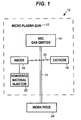
- the plasma spray apparatus 10 includes a plasma gun 12 having an arc gas emitter 14, an anode 16, and a cathode 18.
- An electric arc 20 is generated between the anode 16 and cathode 18.
- a plasma stream 21 is formed when arc gas is injected from the arc gas emitter 14 and passes through the arc 20.
- a powdered material injector 22 dispenses powdered material into the plasma stream which transports the powdered material to the workpiece 24 to form a coating thereon.
- the size of the plasma stream 21 created by the device and/or the power used by the device determines whether the device is considered a microplasma spray apparatus. When the plasma stream 21 is small and/or the power used by the device is low, the device is considered a microplasma spray device.
- Fig. 1 displays a microplasma spray device.
- the powdered material can form a solid coating with a thickness of approximately 0.0015 to 0.006 inches (0.038 mm to 0.152 mm) in a desired location on the workpiece 24.
- the coating material may be virtually any metallic, non-metallic or intermetallic powder, including the materials described above and ceramic-based materials.
- an electric arc 20 is generated between the anode 16 and cathode 18 of the plasma gun 12.
- Arc gas such as, but not limited to argon, is emitted into the electric arc 20 formed between the anode 16 and the cathode 18. It should be understood that in practice the arc gas can be emitted prior to generating the electric arc.
- the electric arc 20 ionizes the gas to create the plasma gas stream 21. The ionization process removes electrons from the arc gas, causing the arc gas to become temporarily unstable.
- the arc gas heats up to approximately 20,000°F to 30,000°F (11097°C to 16426°C) as it re-stabilizes.
- the plasma stream cools rapidly after passing through the electric arc.
- FIG. 2 an exploded view of such a plasma spray apparatus is again referred to by reference numeral 10.
- the plasma spray apparatus 10 is operable for coating a workpiece, including, but not limited to at least a portion of a compressor blade 72 in a gas turbine engine (not shown).
- a gas turbine engine not shown
- teachings of disclosure can be used to coat myriad other surfaces, including those on aircraft, land-based vehicles, weapons, sea-faring vessels and the like.
- the plasma spray apparatus 10 includes the aforementioned plasma gun 12 having an anode 16 and a cathode 18.
- the cathode 18 is further depicted to include an insulated body 26 with an electrode 28 extending therefrom.
- the cathode 18 can also include threads 30 for threadingly engaging the plasma gun 12.
- the cathode 18 can also include an O-ring seal 32 to seal the leak path that is created at the interface between the cathode 18 and the plasma gun 12.
- a powdered material injector 22 injects powdered material 34 into the plasma gas stream 21.
- the powdered material 34 is heated and super plasticized in the plasma stream 21 and is deposited on the compressor blade 72 (see Fig. 4) where it cools and re-solidifies to form the coating.
- the powdered material injector 22 includes a powder hopper 36 for holding and feeding the powdered material 34 into the plasma stream 21.
- the hopper 36 can be connected to the plasma gun 12 through a conduit 38 such as a flexible hose or the like.
- the conduit 38 can be connected via a threaded fitting 39 to a powder injector nozzle 40.
- the powder injector nozzle 40 can extend through an aperture 42 formed in the anode 16.
- the powder injector nozzle 40 can threadingly connect to the anode 16 via threads 43.
- anodes are typically formed from a copper-tungsten alloy and provide very limited service life of approximately 10 to 20 minutes in a plasma spray apparatus 10. Copper and other similar metals have melting temperatures that are lower than the anode operating temperature. These metals can melt and cause the edge of the anode 16 to become molten and initiate cavitation erosion along an upper edge of the anode. In order to produce high quality coatings, the edge of the anode must remain relatively sharp. To achieve this, a commercially pure sintered tungsten material has been developed to produce a more robust anode. Test results using anodes made from sintered tungsten material has shown marked improvements in the erosion resistance over prior art anodes. Utilizing commercially pure tungsten in the anode 16 has increased the service life of the anode 16 to approximately between 10 and 20 hours.
- a nozzle shroud 46 positioned on a forward wall 48 of the plasma gun 12 holds a nozzle insert 50 and permits the electrode 28 to extend through a center aperture 52 formed in the nozzle shroud 46.
- the nozzle insert 50 can be threadingly attached to an end of the nozzle shroud 46.
- a shield gas cap 54 is positioned over the nozzle shroud 46.
- An insulator 56 is positioned between the shield gas cap 54 and the nozzle shroud 46 to electrically isolate the shield gas cap 54 from the nozzle shroud 46.
- the shield gas cap 54 can be pressed fit onto the nozzle shroud 46 and over the insulator 56.
- the shield gas cap 54 includes a plurality of through apertures 58 for permitting shield gas to flow therethrough and shield the arc gas from ambient atmosphere.
- a center aperture 60 formed in the shield gas cap 54 permits high velocity arc gas to pass through and into the electric arc.
- Cooling fluid such as water or the like, can be utilized to cool the plasma gun 12.
- the cooling fluid is delivered to the plasma gun 12 via a cooling fluid hose 62.
- the cooling fluid traverses through internal passages (not shown) in the plasma gun 12 and flows through an inlet passage 64, into an anode holder 66 and back through an outlet passage 68.
- the cooling fluid reduces the temperature of the anode 16 during operation of the plasma gun 12.
- the cooling flow rate may be approximately 0.1 to 1.0 gallons per minute.
- a second conduit 70 can be connected to the plasma gun 12.
- the second conduit may be operable for providing electrical power, arc gas, and/or shield gas to the plasma gun 12.
- the electrode 28 of the cathode 18 is shown in an enlarged view.
- the electrode 28 can have a circular cross-section, for example, of approximately 1/16 th inch (1.59 mm) in diameter, although other dimensions are certainly possible.
- the electrode 28 can include a tip 65 that is tapered, for example, by machining at an angle A to form a substantially flat upper surface 67.
- the angle A can range between 0 and 90 degrees, but in one embodiment the angle A ranges between approximately 8 and 10 degrees.
- a distal end of the tip 65 can then be machined flat to a desired height B. In one embodiment the height B can range from .008 to .010 inches (0.2 mm to 0.25 mm).
- the height B can be defined as approximately between 10% and 20% of a diameter or a width of the electrode.
- the electrode can be formed from any electrically conductive material such as a copper alloy, but has been found to be advantageously formed from thoriated tungsten.
- a localized area of the compressor blade 72 such as a blade root 74, can be spray coated with powdered material 34.
- the plasma gas stream 21 is directed toward the portion of the compressor blade 72 to be coated.
- the plasma gun 12 is operated at a relatively low power range of between approximately 0.5 Kilowatts and 4 Kilowatts.
- the low power output of the plasma gun 12 significantly reduces the heat flow into the compressor blade 72 over that of conventional coating methods.
- the maximum surface temperature of the compressor blade 72 caused by the coating process is approximately 200°F (93°C).
- Such low power output and resulting low temperature on blade 72 allows the plasma gun 12 to apply powdered material 34 to a thin wall area of the compressor blade 72 without distorting the compressor blade 72 because the localized stresses caused by high thermal gradients do not exist.
- the plasma gun 12 can apply coating material in narrow strips of, for example, about 0.5 to about 5 mm in width. This permits accurate surface coating even with a hand held device.
- the narrow strips of coating substantially eliminate the need for masking or otherwise covering the compressor blade.72 in areas where the coating is unwanted.
- the narrow spray pattern is controlled by the nozzle opening size.
- the hand held version of the plasma gun 12 can spray coatings on components even while they remain in an installed condition, such as in an engine or the like.
- the arc gas flow rate of the plasma apparatus 10 may be between approximately0.5 and 3 liters per minute, although other rates are certain possible.
- the arc gas and shield gas are typically argon, but any suitable inert gas can be utilized as is known to those skilled in the art.
- the shield gas flow rate could range between approximately 2 and 8 liters per minute for a typical application.
- the powder hopper 36 holds the powdered material 34 prior to being injected into the plasma gas stream 21 by the powder injector 22. Powdered material 34 can be transferred to the workpiece from between approximately 1 to 30 grams per minute.
- the plasma gun 12 can typically apply the coating from distances ranging from approximately 1.5 inches to 8 inches (38 mmto 203 mm) to the workpiece, but can vary depending on the coating application requirements.
- the plasma spray gun 12 provides unlimited angles of orientation relative to the workpiece because the pressurized powder feed system uses carrier gas to entrain and deliver the powdered material 34 to the plasma stream 21 and does not rely on gravitation as prior art systems did.
- Compressed carrier gas such as an inert gas flows through the powder injector 22.
- Powdered material 34 can be entrained with the carrier gas as is known to those skilled in the art.
- the carrier gas will flow through the powder injector 22 at any angle of orientation and thus does not rely on gravitational forces to deliver powdered material 34 to the plasma stream 21.
- the plasma stream 21 provides a venturi effect with respect to the powder injector 22.
- the high velocity flow rate of the plasma stream 21 across the powder injector 22 generates a low pressure region which augments the flow rate of the carrier gas and the powdered material 34 through the powder injector 22.
- the plasma spray gun 12 generates a relatively low noise level that ranges from between 40 and 70 decibels due to the low power output, thereby making the apparatus 10 suitable for hand held application.
- Current U.S. government regulations require hearing protection when environmental noise reaches 85 decibels.
- the plasma spray apparatus 10 can be hand held or alternatively held in a fixture (not shown) such as one that is computer controlled.
- a residual amount of electric current is transmitted from the anode 16 to the powder injector 22.
- This residual current can cause preheating of the powdered material 34 to occur which facilitates softening of the powdered material 34 prior to entering the plasma stream 21.
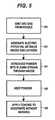
- a block diagram generally describing the operation of the plasma spray apparatus 10 and the plasma spray coating process is illustrated.
- arc gas is emitted from the nozzle insert 50.
- An electric potential is generated between the anode 16 and the cathode 18 of the plasma spray gun 12 and is directed through the arc gas, as described in block 82.
- Arc gas is directed through the electric potential to create the plasma stream 21.
- powdered material 34 is injected into the plasma stream 21.
- the plasma stream heats the powdered material 34 to a "super plasticized" condition such that the powdered material 34 is malleable when it is applied to a workpiece.
- the powdered material 34 is applied to an unmasked substrate. The powdered material 34 then cools and solidifies as a hard coating on the substrate.
Landscapes
- Physics & Mathematics (AREA)
- Electromagnetism (AREA)
- Nozzles (AREA)
- Coating By Spraying Or Casting (AREA)
Abstract
Description
- The present disclosure generally relates to a plasma spray coating apparatus, such as a microplasma spray coating apparatus, for spray coating a workpiece and a method for using the same.
- Plasma coating methods and apparatus are known. For example, one such method and apparatus for plasma flame spray coating material onto a substrate by means of passing a plasma forming gas through a nozzle electrode, and passing an arc forming current between the nozzle electrode and a rear electrode to form a plasma effluent. The method includes introducing coating material into the plasma effluent, passing the plasma effluent axially through a wall shroud extending from the exit of said nozzle electrode, and forming a flame shroud for the plasma effluent. The coating is thereby applied to the substrate.
- One area where such technology is particularly advantageous is in connection with coating various components, particularly aerospace components like gas turbine engines and their components. For example, the blade roots of compressor blades can be coated with material to meet dimensional tolerance requirements for sealing the compressor blade with the compressor wheel and the like. Metallic coatings consisting of copper-nickel, aluminum-copper, and other similar composition materials have been applied in this regard using various conventional plasma spray coating processes. Typically, the coating process requires the workpiece to be masked in areas where the material transfer is not required and/or not desired. Furthermore, the workpiece is typically coated in a dedicated facility such as a gas turbine engine manufacturing plant or repair shop. Prior art methods and apparatus required masking the workpiece and applying the coating in dedicated facilities because the coating equipment was large and not portable and the spray pattern was too wide to accurately control the coating process. It would be desirable to improve the accuracy of spray coating devices so that masking and the like would not be required, as well as permitting hand spray coating repairs in the field.
- In accordance with one aspect of the disclosure, a plasma spray apparatus for coating at least a portion of a workpiece such as a gas turbine compressor blade is provided. A plasma apparatus includes an anode, cathode, and an arc generator for generating an electric arc between the anode and cathode. The apparatus includes an arc gas emitter for injecting gas into the electric arc. The electric arc is operable for ionizing the gas to create a plasma gas stream. A powder feeder provides powdered material to the plasma apparatus. A powder injector nozzle is connected to the powder feeder via a conduit. The powder injector nozzle extends through the anode and is operable for injecting powdered material into the plasma gas stream.
- In accordance with another aspect of the disclosure, a plasma spray apparatus for coating a portion of a workpiece such as a gas turbine compressor blade is provided. A plasma apparatus includes an anode, cathode, and an arc generator for generating an electric arc between the anode and cathode. The apparatus includes an arc gas emitter for injecting gas into the electric arc. The electric arc is operable for ionizing the gas to create a plasma gas stream. A powder feeder provides powdered material to the plasma apparatus. An electrode extending from a cathode housing and terminating at a tip includes a substantially circular cross section along at least a portion of a lengthwise axis. An angled surface extending from the tip toward the cathode housing is formed on the electrode. A substantially flat edge having a predetermined height defines a forward edge of the tip.
- In accordance with another aspect of the present disclosure, a method for injecting powdered material into a plasma gas stream is provided. A powder injector nozzle is positioned through an anode in a plasma apparatus. Powdered material is transported from a powder hopper to the powder injector nozzle. The powdered material is injected into the plasma gas stream prior to being applied to a workpiece.
- Other applications of the present invention will become apparent to those skilled in the art when the following description of a preferred embodiment of the invention is read in conjunction with the accompanying drawings.
-
- Fig. 1 is a schematic representing one embodiment of a microplasma spray apparatus and a workpiece of the present disclosure;
- Fig. 2 is an exploded, perspective view of one embodiment of a microplasma spray apparatus constructed in accordance with the teachings of the disclosure;
- Fig. 3 is an enlarged view of an electrode depicted in Fig. 2.
- Fig. 4 is an assembled perspective view of the microplasma spray apparatus of Fig. 1, applying a coating to a workpiece; and
- Fig. 5 is a flowchart describing one embodiment of a process for plasma spray coating a workpiece.
While the following disclosure is susceptible to various modifications and alternative constructions, certain illustrative embodiments thereof have been shown in the drawings and will be described below in detail. It should be understood, however, that there is no intention to limit the disclosure to the specific forms disclosed, but on the contrary, the intention is to cover all modifications, alternative constructions, and equivalents falling within the spirit and scope of the disclosure as defined by the appended claims. - Referring now to Fig. 1, one embodiment of a
plasma spray apparatus 10 schematically represented by the dashed box outline is depicted. In generalized terms, theplasma spray apparatus 10 includes aplasma gun 12 having anarc gas emitter 14, ananode 16, and acathode 18. Anelectric arc 20 is generated between theanode 16 andcathode 18. Aplasma stream 21 is formed when arc gas is injected from thearc gas emitter 14 and passes through thearc 20. A powderedmaterial injector 22 dispenses powdered material into the plasma stream which transports the powdered material to theworkpiece 24 to form a coating thereon. The size of theplasma stream 21 created by the device and/or the power used by the device determines whether the device is considered a microplasma spray apparatus. When theplasma stream 21 is small and/or the power used by the device is low, the device is considered a microplasma spray device. Fig. 1 displays a microplasma spray device. - For example, the powdered material can form a solid coating with a thickness of approximately 0.0015 to 0.006 inches (0.038 mm to 0.152 mm) in a desired location on the
workpiece 24. The coating material may be virtually any metallic, non-metallic or intermetallic powder, including the materials described above and ceramic-based materials. - In operation, an
electric arc 20 is generated between theanode 16 andcathode 18 of theplasma gun 12. Arc gas such as, but not limited to argon, is emitted into theelectric arc 20 formed between theanode 16 and thecathode 18. It should be understood that in practice the arc gas can be emitted prior to generating the electric arc. Theelectric arc 20 ionizes the gas to create theplasma gas stream 21. The ionization process removes electrons from the arc gas, causing the arc gas to become temporarily unstable. The arc gas heats up to approximately 20,000°F to 30,000°F (11097°C to 16426°C) as it re-stabilizes. The plasma stream cools rapidly after passing through the electric arc. - While a number of different embodiments and structural variations can be constructed to practice such an invention, the following describes one possible embodiment. Referring now to Fig. 2, an exploded view of such a plasma spray apparatus is again referred to by
reference numeral 10. As will be described in detail below, theplasma spray apparatus 10 is operable for coating a workpiece, including, but not limited to at least a portion of acompressor blade 72 in a gas turbine engine (not shown). However, it is to be understood that the teachings of disclosure can be used to coat myriad other surfaces, including those on aircraft, land-based vehicles, weapons, sea-faring vessels and the like. - In the depicted embodiment, the
plasma spray apparatus 10 includes theaforementioned plasma gun 12 having ananode 16 and acathode 18. Thecathode 18 is further depicted to include aninsulated body 26 with anelectrode 28 extending therefrom. Thecathode 18 can also includethreads 30 for threadingly engaging theplasma gun 12. Thecathode 18 can also include an O-ring seal 32 to seal the leak path that is created at the interface between thecathode 18 and theplasma gun 12. - A
powdered material injector 22 injects powderedmaterial 34 into theplasma gas stream 21. Thepowdered material 34 is heated and super plasticized in theplasma stream 21 and is deposited on the compressor blade 72 (see Fig. 4) where it cools and re-solidifies to form the coating. Thepowdered material injector 22 includes apowder hopper 36 for holding and feeding thepowdered material 34 into theplasma stream 21. Thehopper 36 can be connected to theplasma gun 12 through aconduit 38 such as a flexible hose or the like. Theconduit 38 can be connected via a threaded fitting 39 to apowder injector nozzle 40. Thepowder injector nozzle 40 can extend through anaperture 42 formed in theanode 16. Thepowder injector nozzle 40 can threadingly connect to theanode 16 viathreads 43. - Conventional anodes are typically formed from a copper-tungsten alloy and provide very limited service life of approximately 10 to 20 minutes in a
plasma spray apparatus 10. Copper and other similar metals have melting temperatures that are lower than the anode operating temperature. These metals can melt and cause the edge of theanode 16 to become molten and initiate cavitation erosion along an upper edge of the anode. In order to produce high quality coatings, the edge of the anode must remain relatively sharp. To achieve this, a commercially pure sintered tungsten material has been developed to produce a more robust anode. Test results using anodes made from sintered tungsten material has shown marked improvements in the erosion resistance over prior art anodes. Utilizing commercially pure tungsten in theanode 16 has increased the service life of theanode 16 to approximately between 10 and 20 hours. - A
nozzle shroud 46 positioned on aforward wall 48 of theplasma gun 12 holds anozzle insert 50 and permits theelectrode 28 to extend through acenter aperture 52 formed in thenozzle shroud 46. Thenozzle insert 50 can be threadingly attached to an end of thenozzle shroud 46. Ashield gas cap 54 is positioned over thenozzle shroud 46. Aninsulator 56 is positioned between theshield gas cap 54 and thenozzle shroud 46 to electrically isolate theshield gas cap 54 from thenozzle shroud 46. Theshield gas cap 54 can be pressed fit onto thenozzle shroud 46 and over theinsulator 56. Theshield gas cap 54 includes a plurality of throughapertures 58 for permitting shield gas to flow therethrough and shield the arc gas from ambient atmosphere. Acenter aperture 60 formed in theshield gas cap 54 permits high velocity arc gas to pass through and into the electric arc. - Cooling fluid, such as water or the like, can be utilized to cool the
plasma gun 12. The cooling fluid is delivered to theplasma gun 12 via a coolingfluid hose 62. The cooling fluid traverses through internal passages (not shown) in theplasma gun 12 and flows through aninlet passage 64, into ananode holder 66 and back through anoutlet passage 68. The cooling fluid reduces the temperature of theanode 16 during operation of theplasma gun 12. The cooling flow rate may be approximately 0.1 to 1.0 gallons per minute. Asecond conduit 70 can be connected to theplasma gun 12. The second conduit may be operable for providing electrical power, arc gas, and/or shield gas to theplasma gun 12. - Referring now to Fig. 3, the
electrode 28 of thecathode 18 is shown in an enlarged view. Theelectrode 28 can have a circular cross-section, for example, of approximately 1/16th inch (1.59 mm) in diameter, although other dimensions are certainly possible. Theelectrode 28 can include atip 65 that is tapered, for example, by machining at an angle A to form a substantially flatupper surface 67. The angle A can range between 0 and 90 degrees, but in one embodiment the angle A ranges between approximately 8 and 10 degrees. A distal end of thetip 65 can then be machined flat to a desired height B. In one embodiment the height B can range from .008 to .010 inches (0.2 mm to 0.25 mm). For variably sized electrodes, the height B can be defined as approximately between 10% and 20% of a diameter or a width of the electrode. The electrode can be formed from any electrically conductive material such as a copper alloy, but has been found to be advantageously formed from thoriated tungsten. - Referring now to Fig. 4, it is shown that a localized area of the
compressor blade 72, such as ablade root 74, can be spray coated withpowdered material 34. Theplasma gas stream 21 is directed toward the portion of thecompressor blade 72 to be coated. Theplasma gun 12 is operated at a relatively low power range of between approximately 0.5 Kilowatts and 4 Kilowatts. The low power output of theplasma gun 12 significantly reduces the heat flow into thecompressor blade 72 over that of conventional coating methods. The maximum surface temperature of thecompressor blade 72 caused by the coating process is approximately 200°F (93°C). Such low power output and resulting low temperature onblade 72 allows theplasma gun 12 to applypowdered material 34 to a thin wall area of thecompressor blade 72 without distorting thecompressor blade 72 because the localized stresses caused by high thermal gradients do not exist. - The
plasma gun 12 can apply coating material in narrow strips of, for example, about 0.5 to about 5 mm in width. This permits accurate surface coating even with a hand held device. The narrow strips of coating substantially eliminate the need for masking or otherwise covering the compressor blade.72 in areas where the coating is unwanted. The narrow spray pattern is controlled by the nozzle opening size. The hand held version of theplasma gun 12 can spray coatings on components even while they remain in an installed condition, such as in an engine or the like. - The arc gas flow rate of the
plasma apparatus 10 may be between approximately0.5 and 3 liters per minute, although other rates are certain possible.
As stated above, the arc gas and shield gas are typically argon, but any suitable inert gas can be utilized as is known to those skilled in the art. The shield gas flow rate could range between approximately 2 and 8 liters per minute for a typical application. - The
powder hopper 36 holds thepowdered material 34 prior to being injected into theplasma gas stream 21 by thepowder injector 22.Powdered material 34 can be transferred to the workpiece from between approximately 1 to 30 grams per minute. Theplasma gun 12 can typically apply the coating from distances ranging from approximately 1.5 inches to 8 inches (38 mmto 203 mm) to the workpiece, but can vary depending on the coating application requirements. Theplasma spray gun 12 provides unlimited angles of orientation relative to the workpiece because the pressurized powder feed system uses carrier gas to entrain and deliver thepowdered material 34 to theplasma stream 21 and does not rely on gravitation as prior art systems did. - Compressed carrier gas, such as an inert gas, flows through the
powder injector 22.Powdered material 34 can be entrained with the carrier gas as is known to those skilled in the art. The carrier gas will flow through thepowder injector 22 at any angle of orientation and thus does not rely on gravitational forces to deliverpowdered material 34 to theplasma stream 21. Theplasma stream 21 provides a venturi effect with respect to thepowder injector 22. The high velocity flow rate of theplasma stream 21 across thepowder injector 22 generates a low pressure region which augments the flow rate of the carrier gas and thepowdered material 34 through thepowder injector 22. - The
plasma spray gun 12 generates a relatively low noise level that ranges from between 40 and 70 decibels due to the low power output, thereby making theapparatus 10 suitable for hand held application. Current U.S. government regulations require hearing protection when environmental noise reaches 85 decibels. Theplasma spray apparatus 10 can be hand held or alternatively held in a fixture (not shown) such as one that is computer controlled. - In one embodiment, a residual amount of electric current is transmitted from the
anode 16 to thepowder injector 22. This residual current can cause preheating of thepowdered material 34 to occur which facilitates softening of thepowdered material 34 prior to entering theplasma stream 21. - Referring now to Fig. 5, a block diagram generally describing the operation of the
plasma spray apparatus 10 and the plasma spray coating process is illustrated. Initially, atblock 80, arc gas is emitted from thenozzle insert 50. An electric potential is generated between theanode 16 and thecathode 18 of theplasma spray gun 12 and is directed through the arc gas, as described inblock 82. Arc gas is directed through the electric potential to create theplasma stream 21. Atblock 84,powdered material 34 is injected into theplasma stream 21. Atblock 86, the plasma stream heats thepowdered material 34 to a "super plasticized" condition such that thepowdered material 34 is malleable when it is applied to a workpiece. Atblock 88, thepowdered material 34 is applied to an unmasked substrate. Thepowdered material 34 then cools and solidifies as a hard coating on the substrate. - While the preceding text sets forth a detailed description of certain embodiments of the invention, it should be understood that the legal scope of the invention is defined by the claims set forth at the end of this patent. The detailed description is to be construed as exemplary only and does not describe every possible embodiment of the invention since describing every possible embodiment would be impractical, if not impossible. Numerous alternative embodiments could be implemented, using either current technology or technology developed after the filing date of this patent, which would still fall within the scope of the claims defining the invention.
Claims (37)
- A plasma spray apparatus (10) for coating a workpiece, comprising:an anode (16), a cathode (18), and an arc generator generating an electric arc (20) between the anode (16) and cathode (18),a nozzle to emit arc gas into the electric arc (20), the electric arc operable for ionizing the gas to create a plasma gas stream (21); anda feeder extending through the anode (16) to provide powdered material (34) into the plasma gas stream (21).
- The plasma spray apparatus of claim 1, wherein the cathode (18) includes an electrode (28) having a first end extending from a cathode housing and a second end terminating at a tip (65), the electrode operable for conducting electric current.
- The plasma spray apparatus of claim 2, wherein the electrode (28) includes a substantially circular cross section along at least a portion of a lengthwise axis.
- The plasma spray apparatus of claim 2 or 3, wherein the electrode (28) is formed with a desired surface angle (A) extending from the tip (65) toward the cathode housing.
- The plasma spray apparatus of claim 4, wherein the angle (A) is approximately 10 degrees.
- The plasma spray apparatus of any of claims 2 to 5, wherein the tip (65) includes a substantially flat forward edge.
- The plasma spray apparatus of claim 6, wherein the flat forward edge of the tip (65) is formed at a desired height (B).
- A plasma spray apparatus for coating a workpiece, comprising:an anode (16), a cathode (18), and an arc generator to generate an electric arc (20) between the anode (16) and cathode (18),a nozzle to emit arc gas into the electric arc (20), the electric arc ionizing the gas to create a plasma gas stream (21); anda feeder providing powdered material (34) to the plasma gas stream (21);wherein the cathode (18) includes an electrode (28) having a taper terminating at a tip (65) the taper including a substantially flat edge having a predetermined height (B) at the tip (65).
- The plasma spray apparatus of claim 8, wherein the surface angle of the taper is approximately between 8 and 10 degrees.
- The plasma spray apparatus of any of claims 7 to 9, wherein the height (B) of the edge is approximately between 10% and 20% of a width of the electrode (28).
- The plasma spray apparatus of any preceding claim, wherein the plasma spray apparatus (10) is a microplasma spray apparatus.
- The plasma spray apparatus of any preceding claim, wherein the feeder uses a carrier gas to entrain the powdered material (34) through the anode (16).
- The plasma spray apparatus of any preceding claim, further including a powder hopper (36) for holding the powdered material (34) prior to the powdered material being injected into the plasma gas stream (21).
- The plasma spray apparatus of claim 13, wherein the powder hopper (36) and feeder are combined in one apparatus.
- The plasma spray apparatus of any preceding claim, further including a powder injector nozzle connected to the feeder, the powder injector nozzle extending through the anode (16) and injecting powdered material into the plasma gas stream (21).
- The plasma spray apparatus of any preceding claim, wherein the plasma apparatus operates at a power range of between approximately 0.5 Kilowatts and 4 Kilowatts.
- The plasma spray apparatus of any preceding claim, wherein a maximum surface temperature of the workpiece caused by the coating process is approximately 200°F (93°C).
- The plasma spray apparatus of any preceding claim, wherein the plasma apparatus applies the coating material in widths of about 0.5 mm to about 5 mm to the workpiece.
- The plasma spray apparatus of any preceding claim, further including a shield gas cap (54) having shielding gas injected therethrough.
- The plasma spray apparatus of any preceding claim, wherein the powdered material (34) is a metal alloy.
- The plasma spray apparatus of any of claims 1 to 19, wherein the powdered material (34) is a ceramic based coating.
- The plasma spray apparatus of any preceding claim, further including a cooling system for cooling the plasma apparatus.
- The plasma spray apparatus of any preceding claim, wherein the plasma apparatus is operable for spray coating a workpiece at any angle of orientation.
- The plasma spray apparatus of any preceding claim, wherein the plasma apparatus generates a noise level of between approximately 40 and 70 decibels.
- The plasma spray apparatus of any preceding claim, further including a cathode shroud (46) surrounding a portion of the cathode (18).
- The plasma spray apparatus of claim 25, wherein the nozzle is positioned in a receiving aperture formed in the cathode shroud (46).
- The plasma spray apparatus of claim 25 or 26, further including a shield gas cap (54) substantially encompassing the cathode shroud (46), the shield gas cap operable for providing shielding gas as a barrier between the arc gas and an ambient atmosphere.
- The plasma spray apparatus of claim 45, further including a shield cap insulator (56) positioned between the shield gas cap (54) and the cathode shroud (46).
- The plasma spray apparatus of any preceding claim, wherein the anode (16) is formed from a commercially pure tungsten material.
- The plasma spray apparatus of any preceding claim, wherein the anode (16) is formed from sintered tungsten material.
- A method for injecting powdered material (34) into a plasma gas stream (21), comprising:positioning a powder injector nozzle through an anode (16) of a plasma spray apparatus (50),transporting powdered material (34) from a powder hopper (36) to the powder injector nozzle; andinjecting the powdered material (34) into the plasma gas stream (21).
- The method of claim 31, further comprising:entraining powdered material (34) with carrier gas flowing from a powder feeder through the injector nozzle.
- The method claim 31 or 32, further comprising:preheating the powdered material (34) in the powder injector nozzle with electric current running through the anode (16).
- A plasma spray apparatus (10), comprising:an anode (16), cathode (18) and an arc generator for generating an electric arc (20) between the anode (16) and the cathode (18);a nozzle for emitting arc gas into the electric arc (20), the electric arc (20) ionizing the gas to create a plasma gas stream (21); anda feeder for providing powdered material (34) to the plasma gas stream;wherein the feeder provides the powdered material (34) to the plasma gas stream (21) from a direction other than above the plasma gas stream (21).
- The plasma spray apparatus of claim 34, wherein the direction is from beneath the plasma gas stream.
- A plasma spray apparatus, comprising:an anode (16) formed from a commercially pure tungsten material;a cathode (18) operationally coupled to the anode;an arc generator for generating an electric arc (20) between the anode (16) and cathode (18);a nozzle for emitting arc gas into the electric arc (20), the electric arc (20) ionizing the gas to create a plasma gas stream (21); anda feeder for providing powdered material (34) to the plasma gas stream.
- The plasma spray apparatus of claim 34, 35 or 36, wherein the plasma spray apparatus is a microplasma spray apparatus.
Applications Claiming Priority (3)
| Application Number | Priority Date | Filing Date | Title |
|---|---|---|---|
| US10/982,041 US20060091117A1 (en) | 2004-11-04 | 2004-11-04 | Plasma spray apparatus |
| US11/190,136 US20070023402A1 (en) | 2005-07-26 | 2005-07-26 | Methods for repairing workpieces using microplasma spray coating |
| US11/253,868 US20070087129A1 (en) | 2005-10-19 | 2005-10-19 | Methods for repairing a workpiece |
Publications (3)
| Publication Number | Publication Date |
|---|---|
| EP1657322A2 true EP1657322A2 (en) | 2006-05-17 |
| EP1657322A3 EP1657322A3 (en) | 2008-02-27 |
| EP1657322B1 EP1657322B1 (en) | 2013-10-30 |
Family
ID=35708880
Family Applications (1)
| Application Number | Title | Priority Date | Filing Date |
|---|---|---|---|
| EP20050256848 Expired - Lifetime EP1657322B1 (en) | 2004-11-04 | 2005-11-04 | Plasma spray apparatus |
Country Status (1)
| Country | Link |
|---|---|
| EP (1) | EP1657322B1 (en) |
Citations (3)
| Publication number | Priority date | Publication date | Assignee | Title |
|---|---|---|---|---|
| JPS61210170A (en) | 1985-03-14 | 1986-09-18 | Hitachi Zosen Corp | Thermal spraying method of ceramic powder |
| EP0342388A2 (en) | 1988-05-13 | 1989-11-23 | James A. Browning | High-velocity controlled-temperature plasma spray method and apparatus |
| RU2039613C1 (en) | 1992-07-01 | 1995-07-20 | Сибирская аэрокосмическая академия | Plasmatron for depositing, mainly, refractory materials |
Family Cites Families (6)
| Publication number | Priority date | Publication date | Assignee | Title |
|---|---|---|---|---|
| NL7600738A (en) * | 1976-01-23 | 1977-07-26 | Plasmainvent Ag | DEVICE FOR PLASMA SYRINGES. |
| US5233153A (en) * | 1992-01-10 | 1993-08-03 | Edo Corporation | Method of plasma spraying of polymer compositions onto a target surface |
| EP0727504A3 (en) * | 1995-02-14 | 1996-10-23 | Gen Electric | Plasma coating process for improved adhesive properties of coatings on objects |
| DE10023303A1 (en) * | 2000-05-15 | 2002-04-18 | Euromat Ges Fuer Werkstofftech | Process for applying a layer of precious metal and / or a precious metal alloy and their use |
| US7026009B2 (en) * | 2002-03-27 | 2006-04-11 | Applied Materials, Inc. | Evaluation of chamber components having textured coatings |
| JP2006131999A (en) * | 2004-10-29 | 2006-05-25 | United Technol Corp <Utc> | Method for repairing workpiece by using microplasma thermal spraying |
-
2005
- 2005-11-04 EP EP20050256848 patent/EP1657322B1/en not_active Expired - Lifetime
Patent Citations (3)
| Publication number | Priority date | Publication date | Assignee | Title |
|---|---|---|---|---|
| JPS61210170A (en) | 1985-03-14 | 1986-09-18 | Hitachi Zosen Corp | Thermal spraying method of ceramic powder |
| EP0342388A2 (en) | 1988-05-13 | 1989-11-23 | James A. Browning | High-velocity controlled-temperature plasma spray method and apparatus |
| RU2039613C1 (en) | 1992-07-01 | 1995-07-20 | Сибирская аэрокосмическая академия | Plasmatron for depositing, mainly, refractory materials |
Also Published As
| Publication number | Publication date |
|---|---|
| EP1657322A3 (en) | 2008-02-27 |
| EP1657322B1 (en) | 2013-10-30 |
Similar Documents
| Publication | Publication Date | Title |
|---|---|---|
| US8507826B2 (en) | Microplasma spray apparatus and method for coating articles using same | |
| US8334473B2 (en) | Method and apparatus for microplasma spray coating a portion of a compressor blade in a gas turbine engine | |
| US8563890B2 (en) | Method and apparatus for microplasma spray coating a portion of a turbine vane in a gas turbine engine | |
| US8367967B2 (en) | Method and apparatus for repairing thermal barrier coatings | |
| US7115832B1 (en) | Microplasma spray coating apparatus | |
| CN101316676B (en) | Plasma torch with corrosive protected collimator | |
| US20090208662A1 (en) | Methods for Repairing a Workpiece | |
| EP1743951B1 (en) | Microplasma deposition methods | |
| EP1652953B1 (en) | Methods for repairing a workpiece | |
| EP1652952B1 (en) | Methods for repairing workpieces using microplasma spray coating | |
| EP1652954B9 (en) | Method and apparatus for microplasma spray coating a portion of a compressor blade in a gas turbine engine | |
| US20070023402A1 (en) | Methods for repairing workpieces using microplasma spray coating | |
| EP1657322B1 (en) | Plasma spray apparatus | |
| EP1652951B1 (en) | Method for microplasma spray coating a portion of a turbine vane in a gas turbine engine | |
| EP1652955B1 (en) | Method for repairing thermal barrier coatings | |
| EP1749583B1 (en) | Microplasma spray coating apparatus | |
| JP2006185905A (en) | Method and device for applying thermal spray of micro-plasma on compressor blade part of gas turbine engine | |
| JP2006183658A (en) | Method and device for microplasma spray coating a portion of turbine vane in gas turbine engine | |
| JP2006131998A (en) | Microplasma spray coating apparatus | |
| JP2006187762A (en) | Method and apparatus for repairing thermal barrier coating |
Legal Events
| Date | Code | Title | Description |
|---|---|---|---|
| PUAI | Public reference made under article 153(3) epc to a published international application that has entered the european phase |
Free format text: ORIGINAL CODE: 0009012 |
|
| AK | Designated contracting states |
Kind code of ref document: A2 Designated state(s): AT BE BG CH CY CZ DE DK EE ES FI FR GB GR HU IE IS IT LI LT LU LV MC NL PL PT RO SE SI SK TR |
|
| AX | Request for extension of the european patent |
Extension state: AL BA HR MK YU |
|
| PUAL | Search report despatched |
Free format text: ORIGINAL CODE: 0009013 |
|
| AK | Designated contracting states |
Kind code of ref document: A3 Designated state(s): AT BE BG CH CY CZ DE DK EE ES FI FR GB GR HU IE IS IT LI LT LU LV MC NL PL PT RO SE SI SK TR |
|
| AX | Request for extension of the european patent |
Extension state: AL BA HR MK YU |
|
| 17P | Request for examination filed |
Effective date: 20080327 |
|
| 17Q | First examination report despatched |
Effective date: 20080506 |
|
| AKX | Designation fees paid |
Designated state(s): DE GB |
|
| R17C | First examination report despatched (corrected) |
Effective date: 20080506 |
|
| GRAP | Despatch of communication of intention to grant a patent |
Free format text: ORIGINAL CODE: EPIDOSNIGR1 |
|
| GRAP | Despatch of communication of intention to grant a patent |
Free format text: ORIGINAL CODE: EPIDOSNIGR1 |
|
| INTG | Intention to grant announced |
Effective date: 20130724 |
|
| GRAS | Grant fee paid |
Free format text: ORIGINAL CODE: EPIDOSNIGR3 |
|
| GRAA | (expected) grant |
Free format text: ORIGINAL CODE: 0009210 |
|
| AK | Designated contracting states |
Kind code of ref document: B1 Designated state(s): DE GB |
|
| REG | Reference to a national code |
Ref country code: GB Ref legal event code: FG4D |
|
| REG | Reference to a national code |
Ref country code: DE Ref legal event code: R081 Ref document number: 602005041677 Country of ref document: DE Owner name: UNITED TECHNOLOGIES CORP. (N.D.GES.D. STAATES , US Free format text: FORMER OWNER: UNITED TECHNOLOGIES INC., HARTFORD, CONN., US |
|
| REG | Reference to a national code |
Ref country code: DE Ref legal event code: R096 Ref document number: 602005041677 Country of ref document: DE Effective date: 20131224 |
|
| REG | Reference to a national code |
Ref country code: DE Ref legal event code: R097 Ref document number: 602005041677 Country of ref document: DE |
|
| PLBE | No opposition filed within time limit |
Free format text: ORIGINAL CODE: 0009261 |
|
| STAA | Information on the status of an ep patent application or granted ep patent |
Free format text: STATUS: NO OPPOSITION FILED WITHIN TIME LIMIT |
|
| 26N | No opposition filed |
Effective date: 20140731 |
|
| REG | Reference to a national code |
Ref country code: DE Ref legal event code: R097 Ref document number: 602005041677 Country of ref document: DE Effective date: 20140731 |
|
| REG | Reference to a national code |
Ref country code: DE Ref legal event code: R082 Ref document number: 602005041677 Country of ref document: DE Representative=s name: SCHMITT-NILSON SCHRAUD WAIBEL WOHLFROM PATENTA, DE |
|
| REG | Reference to a national code |
Ref country code: DE Ref legal event code: R082 Ref document number: 602005041677 Country of ref document: DE Representative=s name: SCHMITT-NILSON SCHRAUD WAIBEL WOHLFROM PATENTA, DE Ref country code: DE Ref legal event code: R081 Ref document number: 602005041677 Country of ref document: DE Owner name: UNITED TECHNOLOGIES CORP. (N.D.GES.D. STAATES , US Free format text: FORMER OWNER: UNITED TECHNOLOGIES CORP., HARTFORD, CONN., US |
|
| PGFP | Annual fee paid to national office [announced via postgrant information from national office to epo] |
Ref country code: DE Payment date: 20191021 Year of fee payment: 15 |
|
| REG | Reference to a national code |
Ref country code: DE Ref legal event code: R119 Ref document number: 602005041677 Country of ref document: DE |
|
| PG25 | Lapsed in a contracting state [announced via postgrant information from national office to epo] |
Ref country code: DE Free format text: LAPSE BECAUSE OF NON-PAYMENT OF DUE FEES Effective date: 20210601 |
|
| PGFP | Annual fee paid to national office [announced via postgrant information from national office to epo] |
Ref country code: GB Payment date: 20231019 Year of fee payment: 19 |
|
| GBPC | Gb: european patent ceased through non-payment of renewal fee |
Effective date: 20241104 |
|
| PG25 | Lapsed in a contracting state [announced via postgrant information from national office to epo] |
Ref country code: GB Free format text: LAPSE BECAUSE OF NON-PAYMENT OF DUE FEES Effective date: 20241104 |