EP1657169A1 - Vertical crush resistant packaging - Google Patents
Vertical crush resistant packaging Download PDFInfo
- Publication number
- EP1657169A1 EP1657169A1 EP05256856A EP05256856A EP1657169A1 EP 1657169 A1 EP1657169 A1 EP 1657169A1 EP 05256856 A EP05256856 A EP 05256856A EP 05256856 A EP05256856 A EP 05256856A EP 1657169 A1 EP1657169 A1 EP 1657169A1
- Authority
- EP
- European Patent Office
- Prior art keywords
- case
- end closure
- closure flap
- blank
- overlap
- Prior art date
- Legal status (The legal status is an assumption and is not a legal conclusion. Google has not performed a legal analysis and makes no representation as to the accuracy of the status listed.)
- Granted
Links
Images


Classifications
-
- B—PERFORMING OPERATIONS; TRANSPORTING
- B65—CONVEYING; PACKING; STORING; HANDLING THIN OR FILAMENTARY MATERIAL
- B65D—CONTAINERS FOR STORAGE OR TRANSPORT OF ARTICLES OR MATERIALS, e.g. BAGS, BARRELS, BOTTLES, BOXES, CANS, CARTONS, CRATES, DRUMS, JARS, TANKS, HOPPERS, FORWARDING CONTAINERS; ACCESSORIES, CLOSURES, OR FITTINGS THEREFOR; PACKAGING ELEMENTS; PACKAGES
- B65D5/00—Rigid or semi-rigid containers of polygonal cross-section, e.g. boxes, cartons or trays, formed by folding or erecting one or more blanks made of paper
- B65D5/42—Details of containers or of foldable or erectable container blanks
- B65D5/54—Lines of weakness to facilitate opening of container or dividing it into separate parts by cutting or tearing
- B65D5/5405—Lines of weakness to facilitate opening of container or dividing it into separate parts by cutting or tearing for opening containers formed by erecting a blank in tubular form
- B65D5/541—Lines of weakness to facilitate opening of container or dividing it into separate parts by cutting or tearing for opening containers formed by erecting a blank in tubular form the lines of weakness being provided in one or more closure flaps
-
- B—PERFORMING OPERATIONS; TRANSPORTING
- B65—CONVEYING; PACKING; STORING; HANDLING THIN OR FILAMENTARY MATERIAL
- B65D—CONTAINERS FOR STORAGE OR TRANSPORT OF ARTICLES OR MATERIALS, e.g. BAGS, BARRELS, BOTTLES, BOXES, CANS, CARTONS, CRATES, DRUMS, JARS, TANKS, HOPPERS, FORWARDING CONTAINERS; ACCESSORIES, CLOSURES, OR FITTINGS THEREFOR; PACKAGING ELEMENTS; PACKAGES
- B65D5/00—Rigid or semi-rigid containers of polygonal cross-section, e.g. boxes, cartons or trays, formed by folding or erecting one or more blanks made of paper
- B65D5/02—Rigid or semi-rigid containers of polygonal cross-section, e.g. boxes, cartons or trays, formed by folding or erecting one or more blanks made of paper by folding or erecting a single blank to form a tubular body with or without subsequent folding operations, or the addition of separate elements, to close the ends of the body
- B65D5/0227—Rigid or semi-rigid containers of polygonal cross-section, e.g. boxes, cartons or trays, formed by folding or erecting one or more blanks made of paper by folding or erecting a single blank to form a tubular body with or without subsequent folding operations, or the addition of separate elements, to close the ends of the body with end closures formed by inward folding of flaps and securing them by heat-sealing, by applying adhesive to the flaps or by staples
-
- B—PERFORMING OPERATIONS; TRANSPORTING
- B65—CONVEYING; PACKING; STORING; HANDLING THIN OR FILAMENTARY MATERIAL
- B65D—CONTAINERS FOR STORAGE OR TRANSPORT OF ARTICLES OR MATERIALS, e.g. BAGS, BARRELS, BOTTLES, BOXES, CANS, CARTONS, CRATES, DRUMS, JARS, TANKS, HOPPERS, FORWARDING CONTAINERS; ACCESSORIES, CLOSURES, OR FITTINGS THEREFOR; PACKAGING ELEMENTS; PACKAGES
- B65D5/00—Rigid or semi-rigid containers of polygonal cross-section, e.g. boxes, cartons or trays, formed by folding or erecting one or more blanks made of paper
- B65D5/42—Details of containers or of foldable or erectable container blanks
- B65D5/54—Lines of weakness to facilitate opening of container or dividing it into separate parts by cutting or tearing
- B65D5/5405—Lines of weakness to facilitate opening of container or dividing it into separate parts by cutting or tearing for opening containers formed by erecting a blank in tubular form
- B65D5/542—Lines of weakness to facilitate opening of container or dividing it into separate parts by cutting or tearing for opening containers formed by erecting a blank in tubular form the lines of weakness being provided in the container body
Definitions
- This invention relates to packaging formed from foldable sheet materials such as cardboard, paperboard, corrugated board, plastics or the like.
- packaging cases having improved compression resistance as measured for example in the standard BCT test (Box Compression Test).
- Adequate vertical strength is an important consideration for transit packaging as it determines the number of cases that can be safely stacked on top of each other.
- the packaging must be sufficiently strong and rigid so that none of the loads imposed on it are transmitted through the contents.
- Undesirably heavy board grades may have to be used to ensure adequate strength, adding to the packaging material bulk, weight and cost. This is particularly so with packaging that is deliberately provided with lines of weakness delineating a tear-out or tear-off portion, which is removed to reveal the case contents for display and selection by customers, thereby converting the case between transit and display modes.
- corner joint formed in many conventional case styles may be modified so as to contribute better to the case vertical compressive strength.
- the improved strength is particularly, although not exclusively, useful in cases having tear-out portions for conversion between transit and display modes, or which otherwise include features that tend to weaken one or more of their vertical side panels.
- the present invention provides, erected, part-erected or as a blank, a case formed from a blank of foldable sheet material, the blank comprising opposed ends secured in overlapping relation to form a tubular structure on erection, in which the overlap is present towards the centre of a vertical panel of the erected case characterised in that in an overlap region rupturable lines of weakness surround the overlap region.
- the case will differ from for example a conventional FEFCO 0201 standard case in having the overlapping blank ends towards the centre of a composite vertical panel, instead of at a corner.
- the double thickness of material at the overlap has been found to provide increased vertical strength when moved away from the corner region.
- the vertical crush strength of the panel is therefore not significantly compromised.
- the degree of overlap may be varied to provide the required degree of reinforcement. At one extreme, the entire panel may form the overlap region so as to be formed from a double thickness of material. However, less material is used and often adequate strength can be obtained when the overlap is confined to the central region of the panel only.
- the panel in which the overlap is formed may carry a case end closure flap, formed from separate parts carried by the opposed ends of the blank and which are brought together when the blank ends are secured together to form the tubular structure.
- the separate closure flap parts may be overlapped and secured to form the end closure flap.
- This overlap region in the end closure flap preferably lies outside the areas to which end closure flaps on the adjacent sides of the case are secured, so as to provide flat, uninterrupted areas for securing the inner and outer end closure flaps together.
- Such a case is therefore readily machine erectable, with the end flaps for example secured using hot melt adhesive.
- the panel in which the overlap is formed carries an end closure flap which lies on the inside of the closed case (e.g. the shorter closure flap of a rectangular 0201 case)
- the separate parts of this end closure flap may lie adjacent to each other in the case end closures without overlapping, whereby the parts are substantially co-planar, and closure flaps on the adjacent case sides can readily be secured over the end closure flap parts.
- Confronting regions of the of the end closure flap separate parts may comprise interengaging formations.
- a blank of this form is again machine erectable, e.g. with its end closures secured by hot melt adhesive.
- the interengaging formations provide a mechanical key between the parts, ensuring that they properly lock together to form the end closure flap as they are folded in, and/or improving the rigidity of the completed end closure and the strength of the case.
- the confronting regions of the end closure flap parts are preferably offset from the junction between the overlying end closure flaps, so that an outer closure flap overlies the interengaging formations in the erected case. This provides the case with a better seal, as well as a potentially stronger adhesive bond between the various end closure flaps.
- the confronting regions may be offset from the perpendicular plane through the vertical centreline of the panel formed by the overlapping blank ends.
- the lines of weakness in the panel having the overlapping blank ends may extend into an adjacent end closure.
- the lines of weakness may surround the end closure flap carried by the panel having the overlapping blank ends.
- this end closure flap, the attached parts of the adjacent end closure flaps and that part of the vertical panel bounded by the line of weakness may be torn out as a unit, to open the case for display and/or selection of its contents.
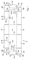
- the blank 10 shown in Figure 1 comprises a pair of longer vertical panels 12a, 12b and a first shorter vertical panel 14.
- a second shorter vertical panel is formed in two portions 14a, 14b at opposite ends of the blank.
- the panels 14a, 12a, 14, 12b and 14b are each folded at 90 degrees to the neighbouring panel(s) along crease lines 16, so that areas 18 of the panels 14a, 14b, delineated by the chain dotted lines 20a, 20b, overlap.
- edge 22a coincides with line 20b and edge 22b coincides with line 20a and the overlap areas 18 may be secured together by hot melt adhesive or any other suitable means.
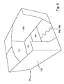
- the blank is thus secured to form a tubular structure 30 as depicted in Figure 2.
- the longer vertical panels 12a, 12b each carry upper 24 and lower 26 end closure flaps.
- the shorter vertical panel 14 similarly carries upper 28 and lower 32 end closure flaps.
- the vertical panel portion 14a carries an upper end closure flap part 28b and a lower end closure flap part 32a.
- the vertical panel portion 14b at the opposite end of the blank carries upper 28a and lower 32b end closure flap parts.
- the end closure flap parts 28a, 28b confront each other without overlapping, in the tubular structure 30.
- the confronting regions of the flap parts 28a, 28b are formed as complementary wavy edges 34a, 34b which interdigitate as the vertical end panel parts 14a, 14b are secured in overlapping relationship.
- the wavy edges 34 provide a mechanical key between the upper end closure flap parts 28a, 28b whilst allowing those parts to lie in the same plane.
- the lower end closure flap parts 32a, 32b have non-overlapping, interdigitating wavy edges 36a, 36b which co-act in the same way as the edges 34a, 34b in the tubular structure 30 and in the erected case.
- the wavy edges 34a, 34b and 36a, 36b are offset to opposite sides of the perpendicular plane extending vertically through the centre of the overlap region 18 (and hence vertically through the centre of the composite shorter vertical panel formed when the panel portions 14a, 14b are secured.together).
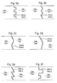
- the precise shape of the confronting edges 34a,b, 36a,b is not critical, and a wide variety of interlocking profiles, both regular and irregular, will serve to provide a mechanical key between the closure flap parts 28a, 28b; 32a, 32b.
- Some additional and non-limiting examples are shown in Figures 2a - 2f. Indeed, where a mechanical key or interlock is not required, the confronting edges 34a,b, 36a,b can be straight. However, for brevity, these edges will be referred to in the following description as wavy edges.
- the blank 10 includes lines of weakness having two parts 38a respectively in each upper end closure flap 24; two parts 38b along the fold lines between the flaps 24 and the long vertical panels 12a, 12b; parts 38c along the fold line between the respective upper end closure panel parts 28a, 28b and the short vertical panel portions 14a, 14b; parts 38d in the short vertical panel portions 14a, 14b; and finally parts 38e along the fold line between those panel portions and the lower end closure flap parts 32a, 32b.
- Punch-out finger hole forming areas 40, 42 are provided at intervals along the lines of weakness.
- the lines of weakness may comprise perforations and/or cuts in the blank.
- the blank may be cut from stock material, perforated and/or creased on a flat bed or rotary cutter, in either a single or a two-pass operation.
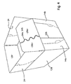
- the shorter lower end closure flaps 32, 32a, 32b of the tubular structure are folded inwardly through 90 degrees.
- the longer lower end closure flaps 26 are then folded inwardly through 90 degrees and secured to the flaps 32, 32a, 32b by hot melt adhesive or other suitable means, to form the base end closure of the case.
- the wavy edges 36a, 36b remain mechanically interlocked and the now inner flap portions 32a, 32b lie in the same plane so as to provide stable support and substantially uniform face contact/resistance for the now outer flaps 26 during the fastening/gluing operation. In effect therefore, the flap parts 32a, 32b are able to act as a single flap.
- the mechanical interlock between the wavy edges 36a, 36b also helps to form a strong, stable base to the erected case.
- the case is now as shown in Figure 3. Due to the offset of the wavy edges 36a, 36b away from the perpendicular plane through the vertical centreline of the composite panel 14a, 14b, the wavy edges 36a, 36b overlie one of the outer base closure flaps 26 (the right-hand one as shown in Figure 6), rather than spanning the distal edges of both outer base closure flaps 26. This provides a stronger, more stable and more leak-proof base structure.
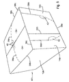
- one or more of the finger hole forming areas 40, 42 are punched out, allowing an end user to insert their fingers and tear out that portion of the case within the lines of weakness 38a-e. These run around the composite inner lid flap 28a, 28b, the attached portions of the outer lid flaps 24 and the attached part of the composite vertical end panel 14a, 14b.
- the resulting opened display case 50 is shown Figure 6.
- the blank 110 shown in Figure 7 is similar to the blank 10 of Figure 1, with analogous parts being indicated by similar references but with an additional "1" prefix.
- one of the shorter vertical panels is formed as a composite by overlapped ends of the blank
- one of the longer side panels is formed as a composite 112a, 112b, with an overlap area 118 delimited by chain dotted lines 120a, 120b. Because this overlap area does not coincide with the fastening areas on the inner (shorter) end closure flaps 128, 132 in the erected case (but instead lies between these fastening areas), there is no need to maintain the closure flap part 124a co-planar with the part 124b or the part 126a co-planar with the part 126b in order to form strong and stable end closures.
- the confronting, interlocking edge features 34a, 34b, 36a, 36b of Figure 1 can therefore be omitted and instead the overlap area 118 can be continued upwardly and downwardly in the blank, into the composite outer (longer) end closure flaps 124a, 124b and 126a, 126b.
- the punch out areas 42 are replaced by regions 144 which are removed prior to forming the blank into the tubular structure.
- the invention improves the vertical crush resistance of a case by moving the overlap area, normally found along a vertical edge of the case, more towards the centre of one of the vertical panels, this panel therefore being formed as a composite panel with a preferably generally vertically extending overlap area at or towards its centre.
- the additional thickness of the overlap area strengthens and stiffens the panel, and may be used to compensate for any reduction in vertical crush resistance that would otherwise arise e.g. from deliberately forming lines of weakness in and/or around the composite panel.
- the corners of the case between adjacent vertical panels, where an overlap area is conventionally located, are inherently relatively stiff and strong, so moving the overlap area away from these areas is not particularly detrimental to the case vertical crushing strength.
Abstract
Description
- This invention relates to packaging formed from foldable sheet materials such as cardboard, paperboard, corrugated board, plastics or the like. In particular it relates to packaging cases having improved compression resistance as measured for example in the standard BCT test (Box Compression Test).
- Adequate vertical strength is an important consideration for transit packaging as it determines the number of cases that can be safely stacked on top of each other. For delicate contents, the packaging must be sufficiently strong and rigid so that none of the loads imposed on it are transmitted through the contents. Undesirably heavy board grades may have to be used to ensure adequate strength, adding to the packaging material bulk, weight and cost. This is particularly so with packaging that is deliberately provided with lines of weakness delineating a tear-out or tear-off portion, which is removed to reveal the case contents for display and selection by customers, thereby converting the case between transit and display modes.
- We have found that the corner joint formed in many conventional case styles may be modified so as to contribute better to the case vertical compressive strength. The improved strength is particularly, although not exclusively, useful in cases having tear-out portions for conversion between transit and display modes, or which otherwise include features that tend to weaken one or more of their vertical side panels.
- Cases are known in which a joint is made by overlapping opposing blank ends positioned towards the centre of a side panel, so that the part-erected blank forms a collapsible tubular structure: see, for example, US3771714, US4447002, US5065937.
- Accordingly, the present invention provides, erected, part-erected or as a blank, a case formed from a blank of foldable sheet material, the blank comprising opposed ends secured in overlapping relation to form a tubular structure on erection, in which the overlap is present towards the centre of a vertical panel of the erected case characterised in that in an overlap region rupturable lines of weakness surround the overlap region. Thus, the case will differ from for example a conventional FEFCO 0201 standard case in having the overlapping blank ends towards the centre of a composite vertical panel, instead of at a corner. The double thickness of material at the overlap has been found to provide increased vertical strength when moved away from the corner region. This serves to compensate for any weakening of the panel caused by the presence of the rupturable lines of weakness, such as may be formed to allow removal of the panel or a portion of it. The vertical crush strength of the panel is therefore not significantly compromised. The degree of overlap may be varied to provide the required degree of reinforcement. At one extreme, the entire panel may form the overlap region so as to be formed from a double thickness of material. However, less material is used and often adequate strength can be obtained when the overlap is confined to the central region of the panel only.
- The panel in which the overlap is formed may carry a case end closure flap, formed from separate parts carried by the opposed ends of the blank and which are brought together when the blank ends are secured together to form the tubular structure. When the end closure flap lies on the outside of the closed case (for example, where it is the longer flap for closing a rectangular 0201 case), the separate closure flap parts may be overlapped and secured to form the end closure flap. This overlap region in the end closure flap preferably lies outside the areas to which end closure flaps on the adjacent sides of the case are secured, so as to provide flat, uninterrupted areas for securing the inner and outer end closure flaps together. Such a case is therefore readily machine erectable, with the end flaps for example secured using hot melt adhesive.
- On the other hand, when the panel in which the overlap is formed carries an end closure flap which lies on the inside of the closed case (e.g. the shorter closure flap of a rectangular 0201 case), the separate parts of this end closure flap may lie adjacent to each other in the case end closures without overlapping, whereby the parts are substantially co-planar, and closure flaps on the adjacent case sides can readily be secured over the end closure flap parts. Confronting regions of the of the end closure flap separate parts may comprise interengaging formations. A blank of this form is again machine erectable, e.g. with its end closures secured by hot melt adhesive. Furthermore, the interengaging formations provide a mechanical key between the parts, ensuring that they properly lock together to form the end closure flap as they are folded in, and/or improving the rigidity of the completed end closure and the strength of the case.
- The confronting regions of the end closure flap parts are preferably offset from the junction between the overlying end closure flaps, so that an outer closure flap overlies the interengaging formations in the erected case. This provides the case with a better seal, as well as a potentially stronger adhesive bond between the various end closure flaps. For example, where the outer closure flaps are of equal width, the confronting regions may be offset from the perpendicular plane through the vertical centreline of the panel formed by the overlapping blank ends.
- The lines of weakness in the panel having the overlapping blank ends may extend into an adjacent end closure. In one embodiment, the lines of weakness may surround the end closure flap carried by the panel having the overlapping blank ends. Thus this end closure flap, the attached parts of the adjacent end closure flaps and that part of the vertical panel bounded by the line of weakness may be torn out as a unit, to open the case for display and/or selection of its contents.
- Illustrative embodiments of the invention, and some further preferred features and advantages of it, are described below with reference to the drawings, in which:
- Figure 1 shows a blank for a first transit/display case embodying the invention;
- Figures 2a - 2f show alternative end closure flap part edge profiles;
- Figures 2 - 6 show successive stages in the erection of the blank of Figure 1, and
- Figure 7 shows a blank for a second transit/display case embodying the invention.
- The blank 10 shown in Figure 1 comprises a pair of longer
vertical panels vertical panel 14. A second shorter vertical panel is formed in twoportions panels crease lines 16, so thatareas 18 of thepanels lines edge 22a coincides withline 20b andedge 22b coincides withline 20a and theoverlap areas 18 may be secured together by hot melt adhesive or any other suitable means. The blank is thus secured to form atubular structure 30 as depicted in Figure 2. - Referring mainly still to Figures 1 and 2, the longer
vertical panels vertical panel 14 similarly carries upper 28 and lower 32 end closure flaps. Thevertical panel portion 14a carries an upper endclosure flap part 28b and a lower endclosure flap part 32a. Correspondingly, thevertical panel portion 14b at the opposite end of the blank carries upper 28a and lower 32b end closure flap parts. The end closure flapparts tubular structure 30. The confronting regions of theflap parts complementary wavy edges end panel parts closure flap parts closure flap parts wavy edges edges tubular structure 30 and in the erected case. Thewavy edges panel portions - The precise shape of the
confronting edges 34a,b, 36a,b is not critical, and a wide variety of interlocking profiles, both regular and irregular, will serve to provide a mechanical key between theclosure flap parts confronting edges 34a,b, 36a,b can be straight. However, for brevity, these edges will be referred to in the following description as wavy edges. - The blank 10 includes lines of weakness having two
parts 38a respectively in each upperend closure flap 24; twoparts 38b along the fold lines between theflaps 24 and the longvertical panels parts 38c along the fold line between the respective upper endclosure panel parts vertical panel portions parts 38d in the shortvertical panel portions parts 38e along the fold line between those panel portions and the lower endclosure flap parts hole forming areas - To form the erected case, the shorter lower
end closure flaps end closure flaps 26 are then folded inwardly through 90 degrees and secured to theflaps wavy edges inner flap portions outer flaps 26 during the fastening/gluing operation. In effect therefore, theflap parts wavy edges wavy edges composite panel wavy edges - After filling the case, assembly of the lid or upper end closure proceeds in an analogous way, as shown in Figures 3 - 5. The
upper flap parts wavy edges flap 28 is next folded in to lie in the case lid plane, followed by theflaps 24, secured to theflaps form 40, as shown in Figure 5. Thewavy edges outer lid flap 24 of Figure 5. - To open the case for contents display, one or more of the finger
hole forming areas weakness 38a-e. These run around the compositeinner lid flap vertical end panel display case 50 is shown Figure 6. - The blank 110 shown in Figure 7 is similar to the blank 10 of Figure 1, with analogous parts being indicated by similar references but with an additional "1" prefix. Instead of one of the shorter vertical panels being formed as a composite by overlapped ends of the blank, one of the longer side panels is formed as a composite 112a, 112b, with an
overlap area 118 delimited by chain dottedlines closure flap part 124a co-planar with thepart 124b or thepart 126a co-planar with thepart 126b in order to form strong and stable end closures. The confronting, interlocking edge features 34a, 34b, 36a, 36b of Figure 1 can therefore be omitted and instead theoverlap area 118 can be continued upwardly and downwardly in the blank, into the composite outer (longer) end closure flaps 124a, 124b and 126a, 126b. - In this embodiment, the punch out
areas 42 are replaced byregions 144 which are removed prior to forming the blank into the tubular structure. - The invention improves the vertical crush resistance of a case by moving the overlap area, normally found along a vertical edge of the case, more towards the centre of one of the vertical panels, this panel therefore being formed as a composite panel with a preferably generally vertically extending overlap area at or towards its centre. The additional thickness of the overlap area strengthens and stiffens the panel, and may be used to compensate for any reduction in vertical crush resistance that would otherwise arise e.g. from deliberately forming lines of weakness in and/or around the composite panel. The corners of the case between adjacent vertical panels, where an overlap area is conventionally located, are inherently relatively stiff and strong, so moving the overlap area away from these areas is not particularly detrimental to the case vertical crushing strength.
Claims (10)
- Erected, part-erected or as a blank, a case formed from a blank (10) of foldable sheet material, the blank (10) comprising opposed ends secured in overlapping relation to form a tubular structure (30) on erection, in which the overlap (18, 118) is present in an overlap region towards the centre of a vertical panel (14a, 14b; 112a, 112b) of the erected case characterised in that the rupturable lines of weakness (38a, 38b, 38c, 38d, 38e, 138a, 138b, 138c, 138d, 138d', 138e) surround the overlap region.
- A case as defined in claim 1, in which the panel in which the overlap (18, 118) is formed carries a case end closure flap (28a, 28b; 32a, 32b; 124a, 124b; 126a, 126b).
- A case as defined in claim 2, in which the end closure flap is formed from separate parts (28a, 28b; 32a, 32b; 124a, 124b; 126a, 126b) carried by the opposed ends of the blank and which are brought together when the blank ends are secured together to form the tubular structure (30).
- A case as defined in claim 3, in which the end closure flap lies on the outside of the closed case, the separate closure flap parts (124a, 124b; 126a, 126b) being overlapped and secured to form the end closure flap.
- A case as defined in claim 4, in which the overlap region in the end closure flap (124a, 124b; 126a, 126b) lies outside the areas to which end closure flaps (128, 132) on the adjacent sides of the case are secured.
- A case as defined in claim 3, in which the end closure flap (28a, 28b; 32a, 32b) lies on the inside of the closed case, the closure flap separate parts (28a, 28b; 32a, 32b) lying adjacent to each other in the case end closures without overlapping, whereby the parts are substantially co-planar.
- A case as defined in claim 6, in which confronting regions of the of the end closure flap separate parts (28a, 28b; 32a, 32b) comprise interengaging formations (34a, 34b; 36a, 36b).
- A case as defined in claim 6 or 7, in which the confronting regions of the end closure flap separate parts (28a, 28b; 32a, 32b) are offset from the junction between the overlying end closure flaps.
- A case as defined in any preceding claim, in which the lines of weakness (38a, 138a) extend into an adjacent end closure (24; 128).
- A case as defined in claim 9, in which the lines of weakness (38a, 38b, 38c, 138a, 138b, 138b) surround the end closure flap (28a, 28b; 124a, 124b) carried by the panel having the overlapping blank ends.
Applications Claiming Priority (1)
| Application Number | Priority Date | Filing Date | Title |
|---|---|---|---|
| GB0424627A GB2419872A (en) | 2004-11-08 | 2004-11-08 | Vertical crush resistant packaging |
Publications (3)
| Publication Number | Publication Date |
|---|---|
| EP1657169A1 true EP1657169A1 (en) | 2006-05-17 |
| EP1657169B1 EP1657169B1 (en) | 2007-01-17 |
| EP1657169B8 EP1657169B8 (en) | 2007-03-14 |
Family
ID=33523339
Family Applications (1)
| Application Number | Title | Priority Date | Filing Date |
|---|---|---|---|
| EP20050256856 Not-in-force EP1657169B8 (en) | 2004-11-08 | 2005-11-04 | Vertical crush resistant packaging |
Country Status (4)
| Country | Link |
|---|---|
| EP (1) | EP1657169B8 (en) |
| DE (1) | DE602005000471D1 (en) |
| ES (1) | ES2281060T3 (en) |
| GB (1) | GB2419872A (en) |
Cited By (3)
| Publication number | Priority date | Publication date | Assignee | Title |
|---|---|---|---|---|
| JP2011088659A (en) * | 2009-10-26 | 2011-05-06 | Ryoko Sangyo Kk | Cutting line for plastic sheets, plastic sheet and packaging case having the same |
| WO2018034887A1 (en) | 2016-08-19 | 2018-02-22 | Dow Global Technologies Llc | Low stress packaging design to minimize pellet blocking |
| JP6343731B1 (en) * | 2018-03-07 | 2018-06-13 | 大王パッケージ株式会社 | Box sheet, box sheet manufacturing method and Thomson mold |
Families Citing this family (1)
| Publication number | Priority date | Publication date | Assignee | Title |
|---|---|---|---|---|
| JP2014097803A (en) * | 2012-11-13 | 2014-05-29 | Japan Pack Kk | Packing box with spout |
Citations (4)
| Publication number | Priority date | Publication date | Assignee | Title |
|---|---|---|---|---|
| US3315875A (en) * | 1964-01-17 | 1967-04-25 | Dynamit Nobel Ag | Dispensing container |
| US3747801A (en) * | 1971-09-30 | 1973-07-24 | E Graser | Returnable wrap around |
| US3900158A (en) * | 1973-10-26 | 1975-08-19 | Int Paper Co | Dispenser carton |
| US4497433A (en) * | 1982-09-03 | 1985-02-05 | Rock-Tenn Company | Combination food tray |
Family Cites Families (6)
| Publication number | Priority date | Publication date | Assignee | Title |
|---|---|---|---|---|
| US3771714A (en) * | 1972-04-10 | 1973-11-13 | Container Corp | Easy packing deep container |
| US4447002A (en) * | 1981-11-02 | 1984-05-08 | The Mead Corporation | Center special slotted containers having self-squaring joints |
| US5065937A (en) * | 1991-01-25 | 1991-11-19 | Container Corporation Of America | Container with end wall opening for handle access |
| US5108030A (en) * | 1991-06-25 | 1992-04-28 | Riverwood International Corporation | Sleeve-type article carrier |
| US6189780B1 (en) * | 2000-04-03 | 2001-02-20 | Allen Kanter | Display container having integral reinforcement |
| US20030146126A1 (en) * | 2002-02-04 | 2003-08-07 | Allen Kanter | Stackable container having support flanges |
-
2004
- 2004-11-08 GB GB0424627A patent/GB2419872A/en active Pending
-
2005
- 2005-11-04 EP EP20050256856 patent/EP1657169B8/en not_active Not-in-force
- 2005-11-04 ES ES05256856T patent/ES2281060T3/en active Active
- 2005-11-04 DE DE200560000471 patent/DE602005000471D1/en active Active
Patent Citations (4)
| Publication number | Priority date | Publication date | Assignee | Title |
|---|---|---|---|---|
| US3315875A (en) * | 1964-01-17 | 1967-04-25 | Dynamit Nobel Ag | Dispensing container |
| US3747801A (en) * | 1971-09-30 | 1973-07-24 | E Graser | Returnable wrap around |
| US3900158A (en) * | 1973-10-26 | 1975-08-19 | Int Paper Co | Dispenser carton |
| US4497433A (en) * | 1982-09-03 | 1985-02-05 | Rock-Tenn Company | Combination food tray |
Cited By (4)
| Publication number | Priority date | Publication date | Assignee | Title |
|---|---|---|---|---|
| JP2011088659A (en) * | 2009-10-26 | 2011-05-06 | Ryoko Sangyo Kk | Cutting line for plastic sheets, plastic sheet and packaging case having the same |
| WO2018034887A1 (en) | 2016-08-19 | 2018-02-22 | Dow Global Technologies Llc | Low stress packaging design to minimize pellet blocking |
| JP6343731B1 (en) * | 2018-03-07 | 2018-06-13 | 大王パッケージ株式会社 | Box sheet, box sheet manufacturing method and Thomson mold |
| JP2019156403A (en) * | 2018-03-07 | 2019-09-19 | 大王パッケージ株式会社 | Sheet for box making, manufacturing method of sheet for box making and thomson mold |
Also Published As
| Publication number | Publication date |
|---|---|
| EP1657169B1 (en) | 2007-01-17 |
| EP1657169B8 (en) | 2007-03-14 |
| GB0424627D0 (en) | 2004-12-08 |
| ES2281060T3 (en) | 2007-09-16 |
| GB2419872A (en) | 2006-05-10 |
| DE602005000471D1 (en) | 2007-03-08 |
Similar Documents
| Publication | Publication Date | Title |
|---|---|---|
| US3708108A (en) | Flip top carton | |
| CN101253099B (en) | Octagonal bulk bin with self-locking webbed bottom flaps | |
| US5775576A (en) | Flip-top reclosable carton with reduced-weight liner | |
| KR100322226B1 (en) | Can packaging container divided into two layers and its manufacturing method | |
| US4319710A (en) | Reinforced end sealed container | |
| US2151472A (en) | Carton | |
| US8408452B2 (en) | Container with modified corner | |
| US5370303A (en) | One piece grape box | |
| EP0666218B1 (en) | Blank for obtaining an American box which is easy to open and the box thus obtained | |
| US8011565B2 (en) | Multi-sided tray bliss container | |
| US9481486B2 (en) | Container with secure audible closure | |
| US4989735A (en) | Dispensing carton | |
| AU2008249440B2 (en) | Leakproof container | |
| US4160519A (en) | Paperboard bulk bin | |
| EP1657169B1 (en) | Vertical crush resistant packaging | |
| US5325989A (en) | Box and blank for packaging powdered soap or the like | |
| JPS6013903B2 (en) | assembled paper box | |
| EP0618870B1 (en) | Package and blank for making the same | |
| US5743462A (en) | Nestable blank for forming a side-filled, flip-top reclosable carton | |
| US4310093A (en) | Folding box and blank for fabricating the same | |
| US11472595B1 (en) | Display container | |
| US4976394A (en) | Two-part carton with carrying handle | |
| US11618607B2 (en) | Leak resistant feature for bliss box | |
| JP7437149B2 (en) | packaging box | |
| EP0628486B1 (en) | Box made of cardboard or the like, having an improved dispensing spout |
Legal Events
| Date | Code | Title | Description |
|---|---|---|---|
| PUAI | Public reference made under article 153(3) epc to a published international application that has entered the european phase |
Free format text: ORIGINAL CODE: 0009012 |
|
| AK | Designated contracting states |
Kind code of ref document: A1 Designated state(s): AT BE BG CH CY CZ DE DK EE ES FI FR GB GR HU IE IS IT LI LT LU LV MC NL PL PT RO SE SI SK TR |
|
| AX | Request for extension of the european patent |
Extension state: AL BA HR MK YU |
|
| 17P | Request for examination filed |
Effective date: 20060601 |
|
| GRAP | Despatch of communication of intention to grant a patent |
Free format text: ORIGINAL CODE: EPIDOSNIGR1 |
|
| GRAS | Grant fee paid |
Free format text: ORIGINAL CODE: EPIDOSNIGR3 |
|
| GRAA | (expected) grant |
Free format text: ORIGINAL CODE: 0009210 |
|
| AK | Designated contracting states |
Kind code of ref document: B1 Designated state(s): AT BE BG CH CY CZ DE DK EE ES FI FR GB GR HU IE IS IT LI LT LU LV MC NL PL PT RO SE SI SK TR |
|
| PG25 | Lapsed in a contracting state [announced via postgrant information from national office to epo] |
Ref country code: CH Free format text: LAPSE BECAUSE OF FAILURE TO SUBMIT A TRANSLATION OF THE DESCRIPTION OR TO PAY THE FEE WITHIN THE PRESCRIBED TIME-LIMIT Effective date: 20070117 Ref country code: SI Free format text: LAPSE BECAUSE OF FAILURE TO SUBMIT A TRANSLATION OF THE DESCRIPTION OR TO PAY THE FEE WITHIN THE PRESCRIBED TIME-LIMIT Effective date: 20070117 Ref country code: DK Free format text: LAPSE BECAUSE OF FAILURE TO SUBMIT A TRANSLATION OF THE DESCRIPTION OR TO PAY THE FEE WITHIN THE PRESCRIBED TIME-LIMIT Effective date: 20070117 Ref country code: PL Free format text: LAPSE BECAUSE OF FAILURE TO SUBMIT A TRANSLATION OF THE DESCRIPTION OR TO PAY THE FEE WITHIN THE PRESCRIBED TIME-LIMIT Effective date: 20070117 Ref country code: FI Free format text: LAPSE BECAUSE OF FAILURE TO SUBMIT A TRANSLATION OF THE DESCRIPTION OR TO PAY THE FEE WITHIN THE PRESCRIBED TIME-LIMIT Effective date: 20070117 Ref country code: AT Free format text: LAPSE BECAUSE OF FAILURE TO SUBMIT A TRANSLATION OF THE DESCRIPTION OR TO PAY THE FEE WITHIN THE PRESCRIBED TIME-LIMIT Effective date: 20070117 Ref country code: NL Free format text: LAPSE BECAUSE OF FAILURE TO SUBMIT A TRANSLATION OF THE DESCRIPTION OR TO PAY THE FEE WITHIN THE PRESCRIBED TIME-LIMIT Effective date: 20070117 Ref country code: LI Free format text: LAPSE BECAUSE OF FAILURE TO SUBMIT A TRANSLATION OF THE DESCRIPTION OR TO PAY THE FEE WITHIN THE PRESCRIBED TIME-LIMIT Effective date: 20070117 |
|
| REG | Reference to a national code |
Ref country code: GB Ref legal event code: FG4D |
|
| AKX | Designation fees paid |
Designated state(s): AT BE BG CH CY CZ DE DK EE ES FI FR GB GR HU IE IS IT LI LT LU LV MC NL PL PT RO SE SI SK TR |
|
| RAP2 | Party data changed (patent owner data changed or rights of a patent transferred) |
Owner name: SOCIETE NORMANDE DE CARTON ONDULE (S.N.C.O.) |
|
| REG | Reference to a national code |
Ref country code: CH Ref legal event code: EP |
|
| REG | Reference to a national code |
Ref country code: IE Ref legal event code: FG4D |
|
| REF | Corresponds to: |
Ref document number: 602005000471 Country of ref document: DE Date of ref document: 20070308 Kind code of ref document: P |
|
| NLT2 | Nl: modifications (of names), taken from the european patent patent bulletin |
Owner name: SOCIETE NORMANDE DE CARTON ONDULE (S.N.C.O.) Effective date: 20070214 |
|
| PG25 | Lapsed in a contracting state [announced via postgrant information from national office to epo] |
Ref country code: SE Free format text: LAPSE BECAUSE OF FAILURE TO SUBMIT A TRANSLATION OF THE DESCRIPTION OR TO PAY THE FEE WITHIN THE PRESCRIBED TIME-LIMIT Effective date: 20070417 Ref country code: BG Free format text: LAPSE BECAUSE OF FAILURE TO SUBMIT A TRANSLATION OF THE DESCRIPTION OR TO PAY THE FEE WITHIN THE PRESCRIBED TIME-LIMIT Effective date: 20070417 |
|
| PG25 | Lapsed in a contracting state [announced via postgrant information from national office to epo] |
Ref country code: IS Free format text: LAPSE BECAUSE OF FAILURE TO SUBMIT A TRANSLATION OF THE DESCRIPTION OR TO PAY THE FEE WITHIN THE PRESCRIBED TIME-LIMIT Effective date: 20070517 |
|
| RIN2 | Information on inventor provided after grant (corrected) |
Inventor name: FODEN, ROY |
|
| PG25 | Lapsed in a contracting state [announced via postgrant information from national office to epo] |
Ref country code: PT Free format text: LAPSE BECAUSE OF FAILURE TO SUBMIT A TRANSLATION OF THE DESCRIPTION OR TO PAY THE FEE WITHIN THE PRESCRIBED TIME-LIMIT Effective date: 20070618 |
|
| NLV1 | Nl: lapsed or annulled due to failure to fulfill the requirements of art. 29p and 29m of the patents act | ||
| REG | Reference to a national code |
Ref country code: CH Ref legal event code: PL |
|
| ET | Fr: translation filed | ||
| REG | Reference to a national code |
Ref country code: ES Ref legal event code: FG2A Ref document number: 2281060 Country of ref document: ES Kind code of ref document: T3 |
|
| PLBE | No opposition filed within time limit |
Free format text: ORIGINAL CODE: 0009261 |
|
| STAA | Information on the status of an ep patent application or granted ep patent |
Free format text: STATUS: NO OPPOSITION FILED WITHIN TIME LIMIT |
|
| PG25 | Lapsed in a contracting state [announced via postgrant information from national office to epo] |
Ref country code: SK Free format text: LAPSE BECAUSE OF FAILURE TO SUBMIT A TRANSLATION OF THE DESCRIPTION OR TO PAY THE FEE WITHIN THE PRESCRIBED TIME-LIMIT Effective date: 20070117 |
|
| 26N | No opposition filed |
Effective date: 20071018 |
|
| PG25 | Lapsed in a contracting state [announced via postgrant information from national office to epo] |
Ref country code: BE Free format text: LAPSE BECAUSE OF FAILURE TO SUBMIT A TRANSLATION OF THE DESCRIPTION OR TO PAY THE FEE WITHIN THE PRESCRIBED TIME-LIMIT Effective date: 20070117 Ref country code: RO Free format text: LAPSE BECAUSE OF FAILURE TO SUBMIT A TRANSLATION OF THE DESCRIPTION OR TO PAY THE FEE WITHIN THE PRESCRIBED TIME-LIMIT Effective date: 20070117 Ref country code: CZ Free format text: LAPSE BECAUSE OF FAILURE TO SUBMIT A TRANSLATION OF THE DESCRIPTION OR TO PAY THE FEE WITHIN THE PRESCRIBED TIME-LIMIT Effective date: 20070117 |
|
| PG25 | Lapsed in a contracting state [announced via postgrant information from national office to epo] |
Ref country code: LV Free format text: LAPSE BECAUSE OF FAILURE TO SUBMIT A TRANSLATION OF THE DESCRIPTION OR TO PAY THE FEE WITHIN THE PRESCRIBED TIME-LIMIT Effective date: 20070117 Ref country code: DE Free format text: LAPSE BECAUSE OF FAILURE TO SUBMIT A TRANSLATION OF THE DESCRIPTION OR TO PAY THE FEE WITHIN THE PRESCRIBED TIME-LIMIT Effective date: 20070418 |
|
| PG25 | Lapsed in a contracting state [announced via postgrant information from national office to epo] |
Ref country code: LT Free format text: LAPSE BECAUSE OF FAILURE TO SUBMIT A TRANSLATION OF THE DESCRIPTION OR TO PAY THE FEE WITHIN THE PRESCRIBED TIME-LIMIT Effective date: 20070117 |
|
| PG25 | Lapsed in a contracting state [announced via postgrant information from national office to epo] |
Ref country code: IT Free format text: LAPSE BECAUSE OF FAILURE TO SUBMIT A TRANSLATION OF THE DESCRIPTION OR TO PAY THE FEE WITHIN THE PRESCRIBED TIME-LIMIT Effective date: 20070117 Ref country code: GR Free format text: LAPSE BECAUSE OF FAILURE TO SUBMIT A TRANSLATION OF THE DESCRIPTION OR TO PAY THE FEE WITHIN THE PRESCRIBED TIME-LIMIT Effective date: 20070418 |
|
| PG25 | Lapsed in a contracting state [announced via postgrant information from national office to epo] |
Ref country code: MC Free format text: LAPSE BECAUSE OF NON-PAYMENT OF DUE FEES Effective date: 20071130 |
|
| PG25 | Lapsed in a contracting state [announced via postgrant information from national office to epo] |
Ref country code: IE Free format text: LAPSE BECAUSE OF NON-PAYMENT OF DUE FEES Effective date: 20071105 |
|
| PG25 | Lapsed in a contracting state [announced via postgrant information from national office to epo] |
Ref country code: EE Free format text: LAPSE BECAUSE OF FAILURE TO SUBMIT A TRANSLATION OF THE DESCRIPTION OR TO PAY THE FEE WITHIN THE PRESCRIBED TIME-LIMIT Effective date: 20070117 |
|
| PG25 | Lapsed in a contracting state [announced via postgrant information from national office to epo] |
Ref country code: CY Free format text: LAPSE BECAUSE OF FAILURE TO SUBMIT A TRANSLATION OF THE DESCRIPTION OR TO PAY THE FEE WITHIN THE PRESCRIBED TIME-LIMIT Effective date: 20070117 |
|
| PG25 | Lapsed in a contracting state [announced via postgrant information from national office to epo] |
Ref country code: LU Free format text: LAPSE BECAUSE OF NON-PAYMENT OF DUE FEES Effective date: 20071104 |
|
| PG25 | Lapsed in a contracting state [announced via postgrant information from national office to epo] |
Ref country code: TR Free format text: LAPSE BECAUSE OF FAILURE TO SUBMIT A TRANSLATION OF THE DESCRIPTION OR TO PAY THE FEE WITHIN THE PRESCRIBED TIME-LIMIT Effective date: 20070117 Ref country code: HU Free format text: LAPSE BECAUSE OF FAILURE TO SUBMIT A TRANSLATION OF THE DESCRIPTION OR TO PAY THE FEE WITHIN THE PRESCRIBED TIME-LIMIT Effective date: 20070718 |
|
| PGFP | Annual fee paid to national office [announced via postgrant information from national office to epo] |
Ref country code: FR Payment date: 20121019 Year of fee payment: 8 |
|
| PGFP | Annual fee paid to national office [announced via postgrant information from national office to epo] |
Ref country code: GB Payment date: 20121115 Year of fee payment: 8 Ref country code: ES Payment date: 20121105 Year of fee payment: 8 |
|
| GBPC | Gb: european patent ceased through non-payment of renewal fee |
Effective date: 20131104 |
|
| REG | Reference to a national code |
Ref country code: FR Ref legal event code: ST Effective date: 20140731 |
|
| PG25 | Lapsed in a contracting state [announced via postgrant information from national office to epo] |
Ref country code: FR Free format text: LAPSE BECAUSE OF NON-PAYMENT OF DUE FEES Effective date: 20131202 Ref country code: GB Free format text: LAPSE BECAUSE OF NON-PAYMENT OF DUE FEES Effective date: 20131104 |
|
| REG | Reference to a national code |
Ref country code: ES Ref legal event code: FD2A Effective date: 20150709 |
|
| PG25 | Lapsed in a contracting state [announced via postgrant information from national office to epo] |
Ref country code: ES Free format text: LAPSE BECAUSE OF NON-PAYMENT OF DUE FEES Effective date: 20131105 |