EP1657114A1 - Navigation device of a vehicle and memory unit mounting system - Google Patents
Navigation device of a vehicle and memory unit mounting system Download PDFInfo
- Publication number
- EP1657114A1 EP1657114A1 EP04027113A EP04027113A EP1657114A1 EP 1657114 A1 EP1657114 A1 EP 1657114A1 EP 04027113 A EP04027113 A EP 04027113A EP 04027113 A EP04027113 A EP 04027113A EP 1657114 A1 EP1657114 A1 EP 1657114A1
- Authority
- EP
- European Patent Office
- Prior art keywords
- memory unit
- support plate
- navigation device
- frame
- mounting system
- Prior art date
- Legal status (The legal status is an assumption and is not a legal conclusion. Google has not performed a legal analysis and makes no representation as to the accuracy of the status listed.)
- Granted
Links
- 238000013016 damping Methods 0.000 claims abstract description 87
- 230000035939 shock Effects 0.000 claims abstract description 25
- 239000012530 fluid Substances 0.000 claims description 7
- 229920002545 silicone oil Polymers 0.000 claims description 7
- XUIMIQQOPSSXEZ-UHFFFAOYSA-N Silicon Chemical compound [Si] XUIMIQQOPSSXEZ-UHFFFAOYSA-N 0.000 claims description 4
- 229910052710 silicon Inorganic materials 0.000 claims description 4
- 239000010703 silicon Substances 0.000 claims description 4
- 230000014759 maintenance of location Effects 0.000 description 13
- 239000000463 material Substances 0.000 description 5
- 238000004519 manufacturing process Methods 0.000 description 4
- 230000006870 function Effects 0.000 description 3
- 238000010521 absorption reaction Methods 0.000 description 2
- XAGFODPZIPBFFR-UHFFFAOYSA-N aluminium Chemical compound [Al] XAGFODPZIPBFFR-UHFFFAOYSA-N 0.000 description 2
- 229910052782 aluminium Inorganic materials 0.000 description 2
- 239000004411 aluminium Substances 0.000 description 2
- 239000003921 oil Substances 0.000 description 2
- -1 polyethylene terephthalate Polymers 0.000 description 2
- 229920000139 polyethylene terephthalate Polymers 0.000 description 2
- 239000005020 polyethylene terephthalate Substances 0.000 description 2
- 239000000853 adhesive Substances 0.000 description 1
- 239000004020 conductor Substances 0.000 description 1
- 230000001419 dependent effect Effects 0.000 description 1
- 238000006073 displacement reaction Methods 0.000 description 1
- 239000013013 elastic material Substances 0.000 description 1
- 229920001971 elastomer Polymers 0.000 description 1
- 239000000806 elastomer Substances 0.000 description 1
- 230000005670 electromagnetic radiation Effects 0.000 description 1
- 239000004744 fabric Substances 0.000 description 1
- 239000011521 glass Substances 0.000 description 1
- 238000000034 method Methods 0.000 description 1
- 239000004033 plastic Substances 0.000 description 1
- 229920003023 plastic Polymers 0.000 description 1
- 229920001296 polysiloxane Polymers 0.000 description 1
- 239000012858 resilient material Substances 0.000 description 1
Images






Classifications
-
- B—PERFORMING OPERATIONS; TRANSPORTING
- B60—VEHICLES IN GENERAL
- B60R—VEHICLES, VEHICLE FITTINGS, OR VEHICLE PARTS, NOT OTHERWISE PROVIDED FOR
- B60R11/00—Arrangements for holding or mounting articles, not otherwise provided for
- B60R11/02—Arrangements for holding or mounting articles, not otherwise provided for for radio sets, television sets, telephones, or the like; Arrangement of controls thereof
- B60R11/0258—Arrangements for holding or mounting articles, not otherwise provided for for radio sets, television sets, telephones, or the like; Arrangement of controls thereof for navigation systems
-
- B—PERFORMING OPERATIONS; TRANSPORTING
- B60—VEHICLES IN GENERAL
- B60R—VEHICLES, VEHICLE FITTINGS, OR VEHICLE PARTS, NOT OTHERWISE PROVIDED FOR
- B60R11/00—Arrangements for holding or mounting articles, not otherwise provided for
- B60R11/02—Arrangements for holding or mounting articles, not otherwise provided for for radio sets, television sets, telephones, or the like; Arrangement of controls thereof
- B60R11/0211—Arrangements for holding or mounting articles, not otherwise provided for for radio sets, television sets, telephones, or the like; Arrangement of controls thereof for record carriers apparatus, e.g. video recorders, tape players or CD players
Definitions
- This invention relates to a navigation system of a vehicle and to a memory unit mounting system for mounting a memory unit in a housing of an onboard electronic system of a vehicle.
- the invention relates especially to a navigation device comprising a memory unit like a hard disk and to a mounting system for mounting said hard disk in the navigation device.
- Computer-based navigation systems are available that provide end-users, such as drivers of vehicles, in which the navigation devices are installed, with various navigation functions or features.
- the navigation devices are able to determine an optimum route from the present position to a predetermined destination.
- the navigation device uses detailed data basis that include data which represent physical features in a geographic region.
- the detailed data base may include data representing the road and intersections and may also include information about the roads such as turn restrictions, speed limits, address ranges and so on.
- a data base may comprise a point of interest (POI) related information providing the end-user with information about monuments, sightseeing places, restaurants, etc.
- POI point of interest
- a navigation device has to read data from the hard disk or fixed disk, when the vehicle is in motion so that the hard disk or memory unit is exposed to vibration or shocks. It is known to fixly connect the memory unit to the housing of the navigation device. However, in this case a proper functioning of reading data from the memory unit cannot be assured in all circumstances, as shocks or vibrations due to the road surface on which the vehicle is moving may disturb the reading of data.
- damping elements are known in combination with disk drives, by way of example in portable computers, such as laptops.
- the disk drive is locked during transportation and the damping elements are mechanically locked, as the damping elements could be destroyed or displaced within the adsorbing mechanism under a strong shock, e.g. when the electronic device comprising the disk drive falls down.
- a memory unit such as a hard disk
- a navigation device of a vehicle comprising a memory unit disposed on a support plate inside a housing of the navigation device.
- the navigation device further comprises absorbing means arranged between said support plate and said memory unit for protecting said memory unit against shock and/or vibration, whereas the absorbing means comprises at least one spring element supporting set memory unit and at least one damping element for absorbing shock and/or vibration of the memory unit.
- the provision of the spring element supporting the memory unit and of the damping element helps to absorb shocks or vibrations in an effective way.
- the spring element carrying the weight of the memory unit helps to absorb vibrations. As the spring element supports the memory unit the damping element, in the position of rest of the memory unit, is not preloaded.
- said at least one damping element is a resilient pad.
- resilient pad means that the damping element is made of a resilient material which is deformed, when a force is applied. The deformation of the pad helps to absorb the forces applied to the memory unit.
- the absorbing characteristics of the absorbing element can be determined.
- the damping element is filled with a silicone fluid, especially a silicon oil.
- a silicone fluid especially a silicon oil.
- damping characteristics and the deformation of the resilient pad can be optimized.
- the fluid-filled pad can easily be deformed, the silicone oil having constant material characteristics.
- the volume of the fluid does not depend on the ambient temperature.
- a memory unit mounting system for mounting a memory unit in a housing of an onboard electronic system of a vehicle
- the mounting system comprising a support plate on which said memory unit is disposed and comprising an absorbing means arranged between said support plate and said memory unit for protecting said memory unit against shock and/or vibration.
- the absorbing means comprises at least one spring element supporting said memory unit and at least one damping element for absorbing shock and/or vibration of the memory unit.
- the combination of the spring element and the damping element helps to obtain good damping characteristics, so that the memory unit can also be used in an environment, where the system is exposed to vibrations or shocks.
- the spring element which supports the memory unit, does not directly contact the memory unit but does support the frame on which the memory unit is disposed.
- the hard disk is fixed on the frame helping to locate the memory unit in its place and in the navigation system.
- the navigation device may comprise a cover, in which the memory unit is arranged, the cover comprising an electrically conducting outer surface and an insulating inner surface.
- the cover comprising an electrically conducting outer surface and an insulating inner surface.
- the outer surface of the cover may comprise an aluminium sheet.
- the insulating inner surface can be made of PET (polyethylene terephthalate) for avoiding electrical contacts of the memory unit to the cover.
- the absorbing means is able to absorb shocks to the memory unit in direction of the support plate, as the absorbing means is arranged between the support plate and the memory unit.
- the memory unit mounting system is often manufactured as a separate module or sub-assembly of the navigation device. As a consequence, the memory unit mounting system may be transported as a sub-assembly. During the transport or during the manufacturing process of the complete navigation device, the memory unit mounting system need not necessarily to have the same orientation as when incorporated into the navigation device. It is also possible that the memory unit is not arranged above the support plate, so that the spring element arranged between the support plate and the memory unit will support the weight of the memory unit.
- a fixing strip is provided, which is attached to the support plate and wrapped around at least a part of the memory unit, which limits the vertical movement of the memory unit in the direction opposite to the support plate.
- the movement of the memory unit in the direction of the support plate is limited by the spring element and by the damping element.
- the fixing strip helps to limit the movement of the support plate so that the spring element and the damping element will not jump out of their position.
- the fixing strip can be made of a flexible material, e.g. PTFE (polytetrafluorethylen). This material is a highly resistant material which does have resilient characteristics, but which does not brake when large forces are applied to it.
- the fixing strip is attached to the support plate at the first end, passes through a first cut-out section provided in the frame, is guided on at least part of a surface of the memory unit, passes through a second cut-out provided on the frame opposite the first cut-out and is fixed to the support plate at the second end.
- the fixing strip also limits the movement of the memory unit relative to the support plate in the horizontal direction. During the assembly process or during transportation before the memory unit mounting system is fixedly attached to the housing of the navigation device, the fixing strip ensures that the absorbing means with the spring element and the damping element will stay at their respective places.
- the cover in which the memory unit is arranged could comprise two vertically disposed resilient extensions which are fixed to the support plate and which limit the movement of the memory unit in the vertical direction opposite to the support plate, and which limit the horizontal movement of the memory unit.
- the resilient extensions are part of the cover and extend horizontally downwards in the direction of the support plate.
- the two vertically disposed extensions may pass through cut-outs provided in the frame, the end of each extension being hooked into a hook provided on the support plate.
- the vertically disposed resilient extensions may have an undulated or sinous form, the undulation providing the resilient properties of the extensions.
- four spring elements are provided, which are attached to the frame and which hold the memory unit provided on the frame in a horizontal orientation. Furthermore, the four spring elements may be provided in such a way that they are attached to the frame in the neighbourhood of the edges of the carrier.
- said at least one damping element is attached to the surface of the frame facing the support plate in spaced relation to the support plate.
- the spring element is configured in such a way, that when carrying the weight of the memory unit it has a length which is larger than the length of the damping element.
- the damping element is attached to the frame and the spring element is provided between the frame and the support plate, the damping element is arranged in spaced relation to the support plate.
- the damping element is in its position of rest and is not deformed due to the weight of the memory unit. This helps to get the optimum absorbing characteristics of the damping element, as the full displacement or the full deformation of the damping element can be used for absorbing shocks or vibrations. If the damping element were already deformed, the damping characteristics would be deteriorated.
- each damping element is arranged inside the spring element, the spring element being configured in such a way, that in the position of rest of the spring element, in which it supports the memory unit, the damping element is arranged in spaced relation to the support plate.
- the damping element comprises a recess provided on the surface facing the support plate.
- the support plate itself may comprise guiding pins fixed to the support plate, which engage the recess provided in the damper and which guide the movement of the memory unit.
- the guiding pins may be press-fitted into recesses provided in the support plate.
- the support plate may comprise a vertically protecting tab situated between two horizontally arranged projections of the frame, the projections limiting maximum horizontal movement of the memory unit.
- the two vertically projecting tabs help to further limit the movement of the memory unit relative to the support plate.
- the support plate is fixed to the bottom surface of the navigation device and is part of the bottom surface of the navigation device.
- the hard disk is to be replaced or should be repaired it is easy to remove the support plate and the memory unit mounting system, which may be screwed to the housing of the navigation device.
- the complete memory unit mounting system is removed, as the board plate, the carrier and the cover comprising the hard disk is held together by the fixing strip or by the two vertically disposed resilient extensions of the cover.
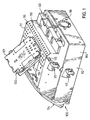
- a navigation device 100 is shown in a perspective view.
- the navigation device is installed in a housing 110, the housing 110 comprising a bottom side 111 and two lateral sides 112 and 113.
- an operation module (not shown) is installed which is used to control the navigation device.
- the navigation device is not limited to an electronic module comprising a navigation module.
- the navigation device is normally part of a multi-media module comprised in the housing 110 comprising an audio module, a radio module and/or a telecommunication module.
- the housing For positioning the housing in a dashboard (not shown) of a vehicle, the housing comprises two pins 115, 116 which help to locate the housing 110 in recesses provided in the dashboard.
- the housing is then connected to the dashboard using the fixing means 117.
- the navigation system 100 further comprises a memory unit mounting module 120, in which a hard disk for storing all the data necessary to guide the user of the vehicle from the present position to a predetermined destination location is installed.
- the mounting module or mounting system 120 comprises a support plate 121.
- the mounting module 120 is not completely introduced into the housing 110.
- the mounting module 120 can be introduced into a recess 119 provided in the bottom side 111 of the housing 110 by pivoting the module 120 in a position in which support plate 121 is flush with the bottom side 111 of the housing.
- the housing 110 further comprises several cut-outs 118 in the housing, which help to dissipate the heat produced of the electronic components of the navigation device 100.
- Fig. 2 the memory unit mounting system or mounting module 120 is shown.
- the mounting module 120 is positioned in the dashboard of the vehicle.
- the support plate 121 which builds a part of the bottom side 111 of the housing 110, carries four spring elements 210, only two of them being visible in Fig. 2.
- the four spring elements 210 support a frame 220.
- the frame 220 carries a cover 230, in which a memory unit 250 is installed.
- the memory unit 250 or the hard disk comprises all the necessary data needed for the navigation device to calculate the route to a predetermined destination location.
- On the one side of the hard disk contact pins 251 are arranged.
- a connector (not shown) is connected to the contact pins 251 in order to assure a data exchange with the other components of the navigation device.
- the frame 220 comprises two vertically upstanding arms 221 which help to correctly connect the connector to the contact pins 251.
- the cover 230 has an electrically conducting outer surface 231 (e.g. aluminium or any other light-weight electrically conducting material).
- the inner surface of the cover is coated with an insulating inner surface in order to assure that there is no electrical contact between the hard disk and the cover.
- the hard disk is fixed to the cover by protrusions 252 of the hard disk 250 which engage recesses 232 provided in the cover 230.
- the weight of the hard disk, the cover and the frame 220 is carried by the four spring elements 210.
- the spring elements 210 help to absorb shocks applied to the hard disk in direction of the support plate 121.
- damping elements 260 are provided on the side of the frame 220 facing the support plate 121.
- the damping elements are filled with silicone oil, the casing of the damping element being made of an elastic material.
- the damping elements 260 are attached to the frame 220.
- the elastic spring elements 210 are configured in such a way, that in the position of rest, when they carry the weight of the frame 220 the hard disk 250, and the cover 230, the spring elements 210 have a vertical extension which is larger than the height of the damping elements 260.
- the damping elements 260 are arranged in spaced relationship to the support plate 121. At the position of rest they are not compressed, as the whole weight is carried by the spring elements 210. When a large force is applied to the navigation device, so that the hard disk 250 moves in the direction of the support plate, the movement of the hard disk is first decelerated by the spring elements. When the hard disk is further moving in direction of the support plate, the damping elements 260 will contact the support plate 121 and will be deformed in dependence of the force applied to the hard disk. As the damping elements 260 are not deformed in the position of rest, they can decelerate the movement of the hard disk much better than it would be the case, if the damping elements were supporting the hard disk 250.
- a fixing strip 270 is provided.
- the fixing strip 270 further helps to maintain the relative position of the support plate 121, the frame 220 and the cover 230 relative to each other.
- the fixing strip 270 may have a self-adhesive inner surface and may be attached to the bottom surface of the support plate 220 with the first end 271.
- the fixing strip is then passed through a first cut-out section 222 provided in the frame 220.
- the fixing strip is then wrapped around the cover 230 before it passes through a second cut-out section (not shown) provided in the frame 220, the second end being also attached to the bottom surface of the support plate 121.
- the fixing strip helps to keep the hard disk 250 in its place.
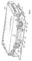
- Fig. 3a a side elevation view of the mounting system 120 is shown.
- the fixing strip 270 helps to limit the movement of the hard disk comprised in the cover 230 in the direction opposite to the support plate (+Z direction). Furthermore, it helps to limit the movement of the hard disk 250 in the ⁇ Y direction.
- the fixing strip is attached in such a way to the support plate 121 is wrapped around the housing 230 so that the movement in the ⁇ Y or +Z direction is not becoming greater than a certain value, e.g. 2 mm.
- the fixing strip could be made of a PTFE glass fabric.
- the fixing strip does not influence the movement of the hard disk used by the absorbing elements (spring element plus damping element). However, the fixing strip helps to avoid that the spring element jumps out of its place.
- the mounting system 120 is transported independently from the navigation device. During the whole manufacturing process, it has to be ensured that the absorbing function is still working, when the mounting system is fixed in its final position in the housing of the navigation device. If the spring element jumps out of its position provided on the support plate and provided on the bottom side of the frame 220, the damping elements 260 would have to carry the weight of the hard disk. In this case, the damping properties of the system would be deteriorated considerably.
- the frame 220 comprises an L-shaped projection 310 comprising a vertically arranged section 311 and a horizontally positioned end section 312.
- the horizontally arranged section 312 is arranged substantially parallel to the frame 220.
- a vertically arranged projecting tab 320 is positioned in the middle of the two horizontally arranged sections 312 of the L-shaped projection 310.
- the protecting tab 320 also limits the movement of the frame 220 and therefore the movement of the hard disk 250, as the inner edges 313 of the sections 312 provide a stop for the projecting tab 320.
- the spring elements 210 abute on the upper surface of the support plate 121 and at the other end abute at a retention element 330.
- the retention element 330 is attached to the frame 220 by the screws 340.
- the damping element 260 is fixedly connected to the retention element 330 and does not come in contact with the support plate 121, when the hard disk 250 is at rest.
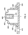
- the damping element 260 is shown in a cross-sectional view.
- the retention element 330 is secured on the frame by inserting the screws 340 (not shown in Fig. 4) in the through-hole 410 provided in the retention element 330.
- the retention element 330 comprises a recess 420, in which a first part 430 of the damping element 260 can be positioned.
- the first part 430 of the damping element may be a synthetic or plastic material having a higher rigidity as a second part 440 of the damping element 260.
- the second part 440 configured as an elastomer bellows, comprises an S-shaped resilient surface 450 with a recessed portion 460 building a cavity, in which guiding pins 510, shown in Fig.
- the inner part of the damping element 260 is filled with silicone oil.
- the silicon oil is often used for the fluid comprised in absorbing elements, as the silicone oil has a nearly temperature independent volume.
- the spring elements support the weight of the frame, and when the hard disk undergoes strong vibrations, the movement of the hard disk is first decelerated by the spring elements, and when the damping elements 260 contact the support plate 121, the damping elements 260 will further decelerate the movement of the hard disk.
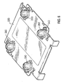
- the support plate 121 comprises through-holes, in which the guiding pins 510 are press-fitted.
- the guiding pins 510 help to guide the movement of the damping elements and therefore help to guide the movement of the spring elements, as the damping elements are arranged inside the spring elements.
- the support plate furthermore comprises two laterally extending arms 520 with opening, in which fixing elements can be introduced to securely attach the support plate to the housing of the navigation device, as shown in Fig. 1.
- the support plate 121 further comprises two vertically arranged extensions 530, which have a curved end 540. This curved end 540 helps to pivot the memory unit mounting module 120 into a position where it is flush with the bottom surface of the housing, as indicated in Fig. 1.
- Fig. 6 the lower surface of the frame 220 for holding the hard disk can be seen.
- the retention elements 330 are fixed to the frame 220 using the screws 340.
- the damping elements 260 are attached to the retention elements 330.
- Fig. 7 the fixing of the retention elements 330 to the cover 230 is shown in more detail.
- an eyelet 710 is cut out and is directed in the vertical direction.
- this eyelet 710 one end of the retention element 330, which is opposite to the through-hole 410, is introduced, the other end of the retention element 330 being fixed using the screw 340.
- Fig. 8 the cover 230 is shown with the fixing strip 270 already been wrapped around the upper surface of the cover 230.
- the hard disk (not shown) can be introduced into the front opening 810 of the cover 230.
- the fixing strip 270 further comprises openings 820. These openings are arranged in such a way that, when the fixing strip is wrapped around the support plate 121, the openings 820 are located in such a way that, when the support plate 121 is completely introduced into the housing of the navigation system, an electrical contact can be arranged between the bottom of the housing and the support plate, as may be seen in Fig. 1.
- a second embodiment of the invention is shown.
- the fixing strip 270 is replaced by two vertically disposed resilient extensions 910, which are integrally built with the cover 920.
- the extensions 910 comprise two resilient arms with an opening 930 at their end, in which a hook 940, cut out in the support plate 121, is engaged.
- the extensions 910 help to limit the movement in the horizontal X-, Y-direction and in the vertical direction opposite to the support plate.
- the vertically disposed extensions 910 pass through cut-outs sections 222 of the frame 220, as already explained in connection with Fig. 2.
- the other part of the absorbing mechanism (spring elements 210 and damping elements 260) corresponds to the embodiments shown in Figs. 1 to 8.
- Fig. 10 the memory unit mounting system of the second embodiment is shown in an exploded view, showing the guiding pins 510, the extensions 910 and the arms 950.
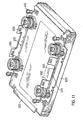
- Fig. 11 the frame 220 and the cover 920 are shown in a bottom view. As can be seen, the extensions 910 pass the cut-outs 222 provided in the frame 220. Furthermore, it is shown that the frame can be connected with the hard disk and to the cover using four threads 930.
- this invention provides a memory unit mounting system and a navigation device comprising a hard disk, in which the hard disk can be installed protected against shocks or vibrations, and in which the hard disk comprises an electrostatic shielding.
- the absorbing system comprising a spring element and a damping element allows an effective absorption of shocks and/or vibrations, so that the hard disk can work even in environments where it is exposed to strong vibrations or shocks.
Landscapes
- Engineering & Computer Science (AREA)
- Mechanical Engineering (AREA)
- Multimedia (AREA)
- Radar, Positioning & Navigation (AREA)
- Remote Sensing (AREA)
- Fittings On The Vehicle Exterior For Carrying Loads, And Devices For Holding Or Mounting Articles (AREA)
- Navigation (AREA)
Abstract
Description
- This invention relates to a navigation system of a vehicle and to a memory unit mounting system for mounting a memory unit in a housing of an onboard electronic system of a vehicle. The invention relates especially to a navigation device comprising a memory unit like a hard disk and to a mounting system for mounting said hard disk in the navigation device.
- Computer-based navigation systems are available that provide end-users, such as drivers of vehicles, in which the navigation devices are installed, with various navigation functions or features. The navigation devices are able to determine an optimum route from the present position to a predetermined destination. In order to provide the navigation functions, the navigation device uses detailed data basis that include data which represent physical features in a geographic region. The detailed data base may include data representing the road and intersections and may also include information about the roads such as turn restrictions, speed limits, address ranges and so on. Furthermore, a data base may comprise a point of interest (POI) related information providing the end-user with information about monuments, sightseeing places, restaurants, etc.
- Given the relatively large size of the data base, geographic data are often stored on a memory unit such as a CD-rom disk. Due to the fact that the information available to the user is getting larger and larger, navigation systems have been developed comprising hard disks. When hard disks are used in navigation devices in vehicles, several problems may arise. First of all, a navigation device has to read data from the hard disk or fixed disk, when the vehicle is in motion so that the hard disk or memory unit is exposed to vibration or shocks. It is known to fixly connect the memory unit to the housing of the navigation device. However, in this case a proper functioning of reading data from the memory unit cannot be assured in all circumstances, as shocks or vibrations due to the road surface on which the vehicle is moving may disturb the reading of data. The use of damping elements is known in combination with disk drives, by way of example in portable computers, such as laptops. However, in these applications the disk drive is locked during transportation and the damping elements are mechanically locked, as the damping elements could be destroyed or displaced within the adsorbing mechanism under a strong shock, e.g. when the electronic device comprising the disk drive falls down.
- Therefore, a need exists to provide a navigation device, in which a memory unit, such as a hard disk, is installed and which is well protected against vibrations or shocks, and which allows a proper functioning of the use of the memory unit, when the vehicle in which it is disposed is moving.
- This need is met by a navigation device and a memory unit mounting system as mentioned in the independent claims. In the dependent claims preferred embodiments of the invention are described.
- According to a fist aspect of the invention, a navigation device of a vehicle is provided comprising a memory unit disposed on a support plate inside a housing of the navigation device. The navigation device further comprises absorbing means arranged between said support plate and said memory unit for protecting said memory unit against shock and/or vibration, whereas the absorbing means comprises at least one spring element supporting set memory unit and at least one damping element for absorbing shock and/or vibration of the memory unit. The provision of the spring element supporting the memory unit and of the damping element helps to absorb shocks or vibrations in an effective way. The spring element carrying the weight of the memory unit helps to absorb vibrations. As the spring element supports the memory unit the damping element, in the position of rest of the memory unit, is not preloaded.
- When the system undergoes stronger vibrations, so that the excursions of the spring element get larger the damping element, unloaded in the position of rest, helps to absorb shocks or vibrations. At the position of rest, the damping element does not carry the weight of the memory unit. As a consequence, the damping element is not deformed and can therefore assure at larger excursions the optimum absorption of forces applied to the memory unit.
- If the damping element carried the weight of the memory unit, the damping characteristics of the damping element would be deteriorated.
- According to a further aspect of the invention, said at least one damping element is a resilient pad. In the present context, resilient pad means that the damping element is made of a resilient material which is deformed, when a force is applied. The deformation of the pad helps to absorb the forces applied to the memory unit. Depending on the geometry of the resilient pad and depending on the amount of deformation of the resilient pad, the absorbing characteristics of the absorbing element can be determined.
- According to a further aspect of the invention, the damping element is filled with a silicone fluid, especially a silicon oil. When the damping element is filled with the fluid, especially the silicone oil, damping characteristics and the deformation of the resilient pad can be optimized. The fluid-filled pad can easily be deformed, the silicone oil having constant material characteristics. As a first approximation, the volume of the fluid does not depend on the ambient temperature.
- According to a further aspect of the invention, a memory unit mounting system for mounting a memory unit in a housing of an onboard electronic system of a vehicle is provided, the mounting system comprising a support plate on which said memory unit is disposed and comprising an absorbing means arranged between said support plate and said memory unit for protecting said memory unit against shock and/or vibration. According to one aspect of the invention, the absorbing means comprises at least one spring element supporting said memory unit and at least one damping element for absorbing shock and/or vibration of the memory unit. As discussed above, the combination of the spring element and the damping element helps to obtain good damping characteristics, so that the memory unit can also be used in an environment, where the system is exposed to vibrations or shocks.
- According to a further aspect of the invention, in the navigation device or the memory unit mounting system on which the memory unit is disposed, the spring element, which supports the memory unit, does not directly contact the memory unit but does support the frame on which the memory unit is disposed. The hard disk is fixed on the frame helping to locate the memory unit in its place and in the navigation system.
- Furthermore, the navigation device may comprise a cover, in which the memory unit is arranged, the cover comprising an electrically conducting outer surface and an insulating inner surface. When memory units, such as hard discs, are used in an electronic system an electronic shielding of the hard disk is preferable, as the electromagnetic radiation emitted from the hard disk could bother the proper functioning of other electronic systems incorporated in the navigation device. The outer surface of the cover may comprise an aluminium sheet. The insulating inner surface can be made of PET (polyethylene terephthalate) for avoiding electrical contacts of the memory unit to the cover. With the use of the absorbing means in combination with the cover comprising an electrically conducting outer surface a navigation device is provided, which at the same provides good damping properties, and which provides an efficient shielding of the memory unit.
- The absorbing means is able to absorb shocks to the memory unit in direction of the support plate, as the absorbing means is arranged between the support plate and the memory unit. During the manufacturing process of the navigation device, the memory unit mounting system is often manufactured as a separate module or sub-assembly of the navigation device. As a consequence, the memory unit mounting system may be transported as a sub-assembly. During the transport or during the manufacturing process of the complete navigation device, the memory unit mounting system need not necessarily to have the same orientation as when incorporated into the navigation device. It is also possible that the memory unit is not arranged above the support plate, so that the spring element arranged between the support plate and the memory unit will support the weight of the memory unit. When the memory unit mounting system is arranged the other way round, it has to be ensured that the arrangement of the different elements, i.e. of the memory unit, the support plate and the absorbing means, rests the same. Furthermore, it has to be assured that the spring element and the damping element stay at predetermined places. Therefore, according to a further aspect of the invention, a fixing strip is provided, which is attached to the support plate and wrapped around at least a part of the memory unit, which limits the vertical movement of the memory unit in the direction opposite to the support plate. The movement of the memory unit in the direction of the support plate is limited by the spring element and by the damping element. The fixing strip helps to limit the movement of the support plate so that the spring element and the damping element will not jump out of their position. The fixing strip can be made of a flexible material, e.g. PTFE (polytetrafluorethylen). This material is a highly resistant material which does have resilient characteristics, but which does not brake when large forces are applied to it.
- According to a further aspect of the invention, the fixing strip is attached to the support plate at the first end, passes through a first cut-out section provided in the frame, is guided on at least part of a surface of the memory unit, passes through a second cut-out provided on the frame opposite the first cut-out and is fixed to the support plate at the second end. With this arrangement of the fixing strip, the assembly consisting of support plate, frame and cover comprising the memory unit can be held together. The fixing strip will be arranged in such a way, that the arrangement of the different parts relative to each other cannot be changed. Especially the fixing strip ensures that the absorbing means comprising the spring element and the damping element stay at a predetermined place, even when the navigation device or the memory unit mounting system is held in different orientations. Furthermore, the fixing strip also limits the movement of the memory unit relative to the support plate in the horizontal direction. During the assembly process or during transportation before the memory unit mounting system is fixedly attached to the housing of the navigation device, the fixing strip ensures that the absorbing means with the spring element and the damping element will stay at their respective places.
- According to a further embodiment of the invention, instead of using the fixing strip, the cover in which the memory unit is arranged could comprise two vertically disposed resilient extensions which are fixed to the support plate and which limit the movement of the memory unit in the vertical direction opposite to the support plate, and which limit the horizontal movement of the memory unit. The resilient extensions are part of the cover and extend horizontally downwards in the direction of the support plate.
- Furthermore, the two vertically disposed extensions may pass through cut-outs provided in the frame, the end of each extension being hooked into a hook provided on the support plate. The vertically disposed resilient extensions may have an undulated or sinous form, the undulation providing the resilient properties of the extensions.
- According to another aspect of the invention, four spring elements are provided, which are attached to the frame and which hold the memory unit provided on the frame in a horizontal orientation. Furthermore, the four spring elements may be provided in such a way that they are attached to the frame in the neighbourhood of the edges of the carrier.
- According to a further aspect of the invention, said at least one damping element is attached to the surface of the frame facing the support plate in spaced relation to the support plate. The spring element is configured in such a way, that when carrying the weight of the memory unit it has a length which is larger than the length of the damping element. As the damping element is attached to the frame and the spring element is provided between the frame and the support plate, the damping element is arranged in spaced relation to the support plate. As a consequence, the damping element is in its position of rest and is not deformed due to the weight of the memory unit. This helps to get the optimum absorbing characteristics of the damping element, as the full displacement or the full deformation of the damping element can be used for absorbing shocks or vibrations. If the damping element were already deformed, the damping characteristics would be deteriorated.
- According to a further aspect of the invention, each damping element is arranged inside the spring element, the spring element being configured in such a way, that in the position of rest of the spring element, in which it supports the memory unit, the damping element is arranged in spaced relation to the support plate.
- When a force is applied to the mounting system so that the memory unit moves relative to the support plate, the movement should be guided. Therefore, according to a further embodiment of the invention the damping element comprises a recess provided on the surface facing the support plate. The support plate itself may comprise guiding pins fixed to the support plate, which engage the recess provided in the damper and which guide the movement of the memory unit. The guiding pins may be press-fitted into recesses provided in the support plate.
- Furthermore, the support plate may comprise a vertically protecting tab situated between two horizontally arranged projections of the frame, the projections limiting maximum horizontal movement of the memory unit. The two vertically projecting tabs help to further limit the movement of the memory unit relative to the support plate. When there is a large excursion of the memory unit relative to the support plate in the horizontal plane, there exists the risk that the absorbing means with its spring element and damping elements are moved out of their locations provided in the system. In this case, the damping of the memory unit could not be assured.
- According to a further aspect of the invention, the support plate is fixed to the bottom surface of the navigation device and is part of the bottom surface of the navigation device. In the case, the hard disk is to be replaced or should be repaired it is easy to remove the support plate and the memory unit mounting system, which may be screwed to the housing of the navigation device. By removing the support plate, the complete memory unit mounting system is removed, as the board plate, the carrier and the cover comprising the hard disk is held together by the fixing strip or by the two vertically disposed resilient extensions of the cover.
- Further aspects of the invention will become apparent to the person skilled in the art with the description of preferred embodiments of the invention with reference to the accompanying drawings, in which
- Fig. 1
- is a perspective view of the bottom of a navigation device comprising absorbing means for absorbing shock and/or vibrations;
- Fig. 2
- is a perspective view of a memory unit mounting system for mounting a memory unit in the navigation device of Fig. 1;
- Figs. 3a and 3b
- show side elevation views of the mounting system of Fig. 2;
- Fig. 4
- is a cross-sectional view of a damping element used for absorbing shock and/or vibration;
- Fig. 5
- is a perspective view of a support plate carrying the memory unit;
- Fig. 6
- is a perspective view of the bottom surface of a carrier on which the memory unit is disposed;
- Fig. 7
- shows in larger scale the arrangement of the damping element at the carrier;
- Fig. 8
- shows a cover in which the memory unit is disposed and shows the fixing strip partly wrapped around the cover;
- Fig. 9
- shows a further embodiment of the memory unit mounting system in a perspective view;
- Fig. 10
- shows a perspective exploded view of the memory unit mounting system of Fig. 9, and
- Fig. 11
- shows a perspective view of the bottom of the carrier with the attached absorbing means.
- In Fig. 1 a
navigation device 100 is shown in a perspective view. The navigation device is installed in ahousing 110, thehousing 110 comprising a bottom side 111 and twolateral sides front side 114 of the housing an operation module (not shown) is installed which is used to control the navigation device. It should be understood that the navigation device is not limited to an electronic module comprising a navigation module. The navigation device is normally part of a multi-media module comprised in thehousing 110 comprising an audio module, a radio module and/or a telecommunication module. For positioning the housing in a dashboard (not shown) of a vehicle, the housing comprises twopins housing 110 in recesses provided in the dashboard. The housing is then connected to the dashboard using the fixing means 117. Thenavigation system 100 further comprises a memoryunit mounting module 120, in which a hard disk for storing all the data necessary to guide the user of the vehicle from the present position to a predetermined destination location is installed. The mounting module or mountingsystem 120 comprises asupport plate 121. In the embodiment shown, the mountingmodule 120 is not completely introduced into thehousing 110. The mountingmodule 120 can be introduced into arecess 119 provided in the bottom side 111 of thehousing 110 by pivoting themodule 120 in a position in whichsupport plate 121 is flush with the bottom side 111 of the housing. Thehousing 110 further comprises several cut-outs 118 in the housing, which help to dissipate the heat produced of the electronic components of thenavigation device 100. - In Fig. 2 the memory unit mounting system or mounting
module 120 is shown. In the orientation, as shown in Fig. 2, the mountingmodule 120 is positioned in the dashboard of the vehicle. When thenavigation device 100 is finally installed in the vehicle, thesupport plate 121, which builds a part of the bottom side 111 of thehousing 110, carries fourspring elements 210, only two of them being visible in Fig. 2. The fourspring elements 210 support aframe 220. Theframe 220 carries acover 230, in which amemory unit 250 is installed. Thememory unit 250 or the hard disk comprises all the necessary data needed for the navigation device to calculate the route to a predetermined destination location. On the one side of the hard disk contact pins 251 are arranged. A connector (not shown) is connected to the contact pins 251 in order to assure a data exchange with the other components of the navigation device. In order to facilitate the fixing of the connector, theframe 220 comprises two verticallyupstanding arms 221 which help to correctly connect the connector to the contact pins 251. When a hard disk is used in a navigation device, it has to be ensured that the electromagnetic irradiation emitted from the hard disk does not interfere with the other electronic components of the navigation device. Therefore, thecover 230 has an electrically conducting outer surface 231 (e.g. aluminium or any other light-weight electrically conducting material). The inner surface of the cover is coated with an insulating inner surface in order to assure that there is no electrical contact between the hard disk and the cover. The hard disk is fixed to the cover byprotrusions 252 of thehard disk 250 which engage recesses 232 provided in thecover 230. - The weight of the hard disk, the cover and the
frame 220 is carried by the fourspring elements 210. Thespring elements 210 help to absorb shocks applied to the hard disk in direction of thesupport plate 121. On the side of theframe 220 facing thesupport plate 121, dampingelements 260 are provided. The damping elements are filled with silicone oil, the casing of the damping element being made of an elastic material. The dampingelements 260 are attached to theframe 220. Theelastic spring elements 210 are configured in such a way, that in the position of rest, when they carry the weight of theframe 220 thehard disk 250, and thecover 230, thespring elements 210 have a vertical extension which is larger than the height of the dampingelements 260. The dampingelements 260 are arranged in spaced relationship to thesupport plate 121. At the position of rest they are not compressed, as the whole weight is carried by thespring elements 210. When a large force is applied to the navigation device, so that thehard disk 250 moves in the direction of the support plate, the movement of the hard disk is first decelerated by the spring elements. When the hard disk is further moving in direction of the support plate, the dampingelements 260 will contact thesupport plate 121 and will be deformed in dependence of the force applied to the hard disk. As the dampingelements 260 are not deformed in the position of rest, they can decelerate the movement of the hard disk much better than it would be the case, if the damping elements were supporting thehard disk 250. - Furthermore, a fixing
strip 270 is provided. The fixingstrip 270 further helps to maintain the relative position of thesupport plate 121, theframe 220 and thecover 230 relative to each other. The fixingstrip 270 may have a self-adhesive inner surface and may be attached to the bottom surface of thesupport plate 220 with thefirst end 271. The fixing strip is then passed through a first cut-outsection 222 provided in theframe 220. The fixing strip is then wrapped around thecover 230 before it passes through a second cut-out section (not shown) provided in theframe 220, the second end being also attached to the bottom surface of thesupport plate 121. - As can be also seen in Figs. 3a and 3b, the fixing strip helps to keep the
hard disk 250 in its place. In Fig. 3a a side elevation view of the mountingsystem 120 is shown. The fixingstrip 270 helps to limit the movement of the hard disk comprised in thecover 230 in the direction opposite to the support plate (+Z direction). Furthermore, it helps to limit the movement of thehard disk 250 in the ±Y direction. The fixing strip is attached in such a way to thesupport plate 121 is wrapped around thehousing 230 so that the movement in the ±Y or +Z direction is not becoming greater than a certain value, e.g. 2 mm. The fixing strip could be made of a PTFE glass fabric. The fixing strip does not influence the movement of the hard disk used by the absorbing elements (spring element plus damping element). However, the fixing strip helps to avoid that the spring element jumps out of its place. During the manufacturing process, the mountingsystem 120 is transported independently from the navigation device. During the whole manufacturing process, it has to be ensured that the absorbing function is still working, when the mounting system is fixed in its final position in the housing of the navigation device. If the spring element jumps out of its position provided on the support plate and provided on the bottom side of theframe 220, the dampingelements 260 would have to carry the weight of the hard disk. In this case, the damping properties of the system would be deteriorated considerably. - In Figs. 3a and 3b another way of limiting the excursion of the
hard disk 250 can be seen. Theframe 220 comprises an L-shapedprojection 310 comprising a vertically arrangedsection 311 and a horizontally positionedend section 312. The horizontally arrangedsection 312 is arranged substantially parallel to theframe 220. As can be seen in Fig. 3a, a vertically arranged projectingtab 320 is positioned in the middle of the two horizontally arrangedsections 312 of the L-shapedprojection 310. The protectingtab 320 also limits the movement of theframe 220 and therefore the movement of thehard disk 250, as theinner edges 313 of thesections 312 provide a stop for the projectingtab 320. - Furthermore, the arrangement of the absorbing system can be seen in more detail. The
spring elements 210 abute on the upper surface of thesupport plate 121 and at the other end abute at aretention element 330. As will be explained later in connection with Figs. 4, 6 and 7, theretention element 330 is attached to theframe 220 by thescrews 340. The dampingelement 260 is fixedly connected to theretention element 330 and does not come in contact with thesupport plate 121, when thehard disk 250 is at rest. - In Fig. 4, the damping
element 260 is shown in a cross-sectional view. Theretention element 330 is secured on the frame by inserting the screws 340 (not shown in Fig. 4) in the through-hole 410 provided in theretention element 330. Theretention element 330 comprises arecess 420, in which afirst part 430 of the dampingelement 260 can be positioned. Thefirst part 430 of the damping element may be a synthetic or plastic material having a higher rigidity as asecond part 440 of the dampingelement 260. Thesecond part 440, configured as an elastomer bellows, comprises an S-shapedresilient surface 450 with a recessedportion 460 building a cavity, in which guiding pins 510, shown in Fig. 5, can be introduced. The inner part of the dampingelement 260 is filled with silicone oil. The silicon oil is often used for the fluid comprised in absorbing elements, as the silicone oil has a nearly temperature independent volume. When a force is applied to thehard disk 250, the dampingelement 260 will be moved in direction of thesupport plate 121. When the dampingelement 260 is in contact with thesupport plate 121, the S-shapedresilient surface 450 will be deformed in such a way that the guiding pin forces theresilient surface 450 in the direction of theretention element 330 until thelower surface 470 of the recess contacts the upper surface of theretention element 330. At the position of rest, the dampingelement 260 is shaped as shown in Fig. 4. The spring elements support the weight of the frame, and when the hard disk undergoes strong vibrations, the movement of the hard disk is first decelerated by the spring elements, and when the dampingelements 260 contact thesupport plate 121, the dampingelements 260 will further decelerate the movement of the hard disk. - In Fig. 5 the upper surface of the
support plate 121 is shown. Thesupport plate 121 comprises through-holes, in which the guiding pins 510 are press-fitted. The guiding pins 510 help to guide the movement of the damping elements and therefore help to guide the movement of the spring elements, as the damping elements are arranged inside the spring elements. The support plate furthermore comprises two laterally extendingarms 520 with opening, in which fixing elements can be introduced to securely attach the support plate to the housing of the navigation device, as shown in Fig. 1. Thesupport plate 121 further comprises two vertically arrangedextensions 530, which have acurved end 540. Thiscurved end 540 helps to pivot the memoryunit mounting module 120 into a position where it is flush with the bottom surface of the housing, as indicated in Fig. 1. - In Fig. 6 the lower surface of the
frame 220 for holding the hard disk can be seen. As shown in the figures, theretention elements 330 are fixed to theframe 220 using thescrews 340. Furthermore, the dampingelements 260 are attached to theretention elements 330. - In Fig. 7 the fixing of the
retention elements 330 to thecover 230 is shown in more detail. In theframe 220 aneyelet 710 is cut out and is directed in the vertical direction. In thiseyelet 710 one end of theretention element 330, which is opposite to the through-hole 410, is introduced, the other end of theretention element 330 being fixed using thescrew 340. - In Fig. 8 the
cover 230 is shown with the fixingstrip 270 already been wrapped around the upper surface of thecover 230. The hard disk (not shown) can be introduced into thefront opening 810 of thecover 230. The fixingstrip 270 further comprisesopenings 820. These openings are arranged in such a way that, when the fixing strip is wrapped around thesupport plate 121, theopenings 820 are located in such a way that, when thesupport plate 121 is completely introduced into the housing of the navigation system, an electrical contact can be arranged between the bottom of the housing and the support plate, as may be seen in Fig. 1. - In Figs. 9 to 11 a second embodiment of the invention is shown. In this embodiment, the fixing
strip 270 is replaced by two vertically disposedresilient extensions 910, which are integrally built with thecover 920. Theextensions 910 comprise two resilient arms with anopening 930 at their end, in which ahook 940, cut out in thesupport plate 121, is engaged. Theextensions 910 help to limit the movement in the horizontal X-, Y-direction and in the vertical direction opposite to the support plate. As in Fig. 2, the vertically disposedextensions 910 pass through cut-outs sections 222 of theframe 220, as already explained in connection with Fig. 2. The other part of the absorbing mechanism (spring elements 210 and damping elements 260) corresponds to the embodiments shown in Figs. 1 to 8. - In Fig. 10 the memory unit mounting system of the second embodiment is shown in an exploded view, showing the guiding pins 510, the
extensions 910 and thearms 950. In Fig. 11 theframe 220 and thecover 920 are shown in a bottom view. As can be seen, theextensions 910 pass the cut-outs 222 provided in theframe 220. Furthermore, it is shown that the frame can be connected with the hard disk and to the cover using fourthreads 930. - In conclusion, this invention provides a memory unit mounting system and a navigation device comprising a hard disk, in which the hard disk can be installed protected against shocks or vibrations, and in which the hard disk comprises an electrostatic shielding. The absorbing system comprising a spring element and a damping element allows an effective absorption of shocks and/or vibrations, so that the hard disk can work even in environments where it is exposed to strong vibrations or shocks.
Claims (33)
- Navigation device of a vehicle comprising:- a memory unit (250) disposed on a support plate (121) inside a housing (110) of the navigation device, and- absorbing means arranged between said support plate (121) and said memory unit (250) for protecting said memory unit against shock and/or vibration, wherein the absorbing means comprises at least one spring element (210) supporting said memory unit (250), and at least one damping element (260) for absorbing shock and/or vibration of the memory unit.
- Navigation device according to claim 1, characterized in that said at least one damping element (260) is a resilient pad.
- Navigation device according to claim 1 or 2, characterized in that the damping element (260) is filled with a silicon fluid, especially a silicone oil.
- Navigation device according to any of the preceding claims, characterized by further comprising a frame (220) on which the memory unit (250) is disposed.
- Navigation device according to any of the preceding claims, characterized by further comprising a cover (230) in which the memory unit (250) is arranged, the cover (230) comprising an electrically conducting outer surface and an insulating inner surface.
- Navigation device according to any of the preceding claims, characterized by further comprising a fixing strip (270) attached to the support plate (121) and wrapped around at least a part of the memory unit (250), which limits the vertical movement of the memory unit (250) in the direction opposite to the support plate (121).
- Navigation device according to claim 6, characterized in that the fixing strip (270) is attached to the support plate (121) at the first end, passes through a first cut-out section (222) provided in the frame (220), is guided on at least part of a surface of the memory unit, passes through a second cut-out provided on the frame opposite the first cut-out and is fixed to the support plate (121) at the second end.
- Navigation device according to claim 7, characterized in that the fixing strip (270) is arranged in such a way that it limits the movement of the memory unit in a horizontal direction.
- Navigation device according claim 5, characterized in that the cover (230) in which the memory unit is arranged comprises two vertically disposed resilient extensions (910) which are fixed to the support plate (121) limiting the movement of the memory unit in the vertical direction opposite to the support plate and limiting the horizontal movement of the memory unit.
- Navigation device according to claim 9, characterized in that the two vertically disposed extensions (910) pass through cut-outs (222) provided in the frame, the end of each extension being hooked into a hook (940) provided on the support plate.
- Navigation device according to any of the preceding claims, characterized in that four spring elements (210) are provided which are attached to the frame (220) and which hold the memory unit provided on the frame in a horizontal orientation.
- Navigation device according to any of claims 4 to 11, characterized in that said at least one damping element (260) is attached to the surface of the frame (220) facing the support plate in spaced relation to the support plate.
- Navigation device according to any of the preceding claims, characterized in that each damping element (260) is arranged inside the spring element (210), the spring element being configured in such a way, that in the position of rest of the spring element (210) in which it supports the memory unit (250), the damping element is arranged in spaced relation to the support plate.
- Navigation device according to any of the preceding claims, characterized in that the damping element (260) comprises a recess (460) provided on the surface facing the support plate.
- Navigation device according to claim 14, characterized by further comprising guiding pins (510) fixed to the support plate (121), which engage the recess (460) provided in the damping element and which guide the movement of the memory unit (250).
- Navigation device according to any of the preceding claims, characterized in that the support plate (121) comprises a vertically projecting tab (320) situated between two horizontally arranged projections (312) of the frame, the projections (312) providing a stop for the maximum horizontal movement of the memory unit.
- Navigation device according to any of the preceding claims, characterized in that the support plate (121) is fixed to the bottom surface of the navigation device and is a part of the bottom surface of the navigation device.
- Memory unit mounting system for mounting a memory unit (250) in a housing (110) of an on-board electronic system of a vehicle comprising:- a support plate (121) on which said memory unit (250) is disposed,- absorbing means arranged between said support plate (121) and said memory unit (250) for protecting said memory unit against shock and/ or vibration, wherein the absorbing means comprises at least one spring element (210) supporting said memory unit, and at least one damping element (260) for absorbing shock and/or vibration of the memory unit.
- Mounting system according to claim 18, characterized in that said at least one damping element (260) is a resilient pad.
- Mounting system according to claim 18 or 19, characterized in that the damping element (260) is filled with a silicon fluid, especially a silicone oil.
- Mounting system according to any of claims 18 to 20, characterized by further comprising a frame (220) on which the memory unit (250) is disposed.
- Mounting system according to any of claims 18 to 21, characterized by further comprising a cover (230) in which the memory unit (250) is arranged, the cover comprising an electrically conducting outer surface and an insulating inner surface.
- Mounting system according to any of claims 18 to 20, characterized by further comprising a fixing strip (270) attached to the support plate (121) and wrapped around at least a part of the memory unit, which limits the vertical movement of the memory unit (250) in the direction opposite to the support plate (121).
- Mounting system according to claim 23, characterized in that the fixing strip (270) is attached to the support plate (121) at the first end, passes through a first cut-out section (222) provided in the frame, is guided on at least part of a surface of the memory unit, passes through a second cut-out provided on the frame opposite the first cut-out and is fixed to the support plate (121) at the second end.
- Mounting system according to claim 24, characterized in that the fixing strip (270) is arranged in such a way that it limits the movement of the memory unit in a horizontal direction.
- Mounting system according claim 22, characterized in that the cover (230) in which the memory unit is arranged comprises two vertically disposed resilient extensions (910) which are fixed to the support plate (121) limiting the movement of the memory unit in the vertical direction opposite to the support plate and limiting the horizontal movement of the memory unit.
- Mounting system according to claim 26, characterized in that the two vertically disposed extensions (910) pass through cut-outs provided in the frame, the end of each extension being hooked into a hook (940) provided on the support plate.
- Mounting system according to any of claims 18 to 27, characterized in that four spring elements (210) are provided which are attached to the frame and which hold the memory unit provided on the frame in a horizontal orientation.
- Mounting system according to any of claims 21 to 29, characterized in that said at least one damping element (260) is attached to the surface of the frame (220) facing the support plate.
- Mounting system according to any of claims 18 to 29, characterized in that each damping element (260) is arranged inside the spring element (210), the spring element being configured in such a way, that in the position of rest of the spring element (210) in which it supports the memory unit (250), the damping element (260) is arranged in spaced relation to the support plate (121).
- Mounting system according to any of claims 18 to 30, characterized in that the damping element (260) comprises a recess (460) provided on the surface facing the support plate.
- Mounting system according to claim 31, characterized by further comprising guiding pins (510) fixed to the support plate, which engage the recess provided in the damping element and which guide the movement of the memory unit.
- Mounting system according to any of claims 18 to 32, characterized in that the support plate (121) comprises a vertically projecting tab (320) situated between two horizontally arranged projections (312) of the frame, the projections providing a stop for the maximum horizontal movement of the memory unit.
Priority Applications (3)
| Application Number | Priority Date | Filing Date | Title |
|---|---|---|---|
| EP04027113A EP1657114B1 (en) | 2004-11-15 | 2004-11-15 | Navigation device of a vehicle and memory unit mounting system |
| AT04027113T ATE539919T1 (en) | 2004-11-15 | 2004-11-15 | MOTOR VEHICLE NAVIGATION DEVICE AND STORAGE UNIT MOUNTING DEVICE |
| US11/280,967 US7428156B2 (en) | 2004-11-15 | 2005-11-15 | Memory unit mounting module for vehicle navigation device |
Applications Claiming Priority (1)
| Application Number | Priority Date | Filing Date | Title |
|---|---|---|---|
| EP04027113A EP1657114B1 (en) | 2004-11-15 | 2004-11-15 | Navigation device of a vehicle and memory unit mounting system |
Publications (2)
| Publication Number | Publication Date |
|---|---|
| EP1657114A1 true EP1657114A1 (en) | 2006-05-17 |
| EP1657114B1 EP1657114B1 (en) | 2012-01-04 |
Family
ID=34927395
Family Applications (1)
| Application Number | Title | Priority Date | Filing Date |
|---|---|---|---|
| EP04027113A Expired - Lifetime EP1657114B1 (en) | 2004-11-15 | 2004-11-15 | Navigation device of a vehicle and memory unit mounting system |
Country Status (3)
| Country | Link |
|---|---|
| US (1) | US7428156B2 (en) |
| EP (1) | EP1657114B1 (en) |
| AT (1) | ATE539919T1 (en) |
Cited By (8)
| Publication number | Priority date | Publication date | Assignee | Title |
|---|---|---|---|---|
| CN107963028A (en) * | 2017-11-28 | 2018-04-27 | 深圳市贝优通新能源技术开发有限公司 | A kind of intelligent vehicle-carrying navigation equipment with shockproof function based on Internet of Things |
| CN108437905A (en) * | 2018-03-15 | 2018-08-24 | 王秋实 | A kind of storage device for vehicle GPS locator |
| CN110072361A (en) * | 2019-04-15 | 2019-07-30 | 湄洲湾职业技术学院 | A kind of protective device of automatic fire fighting equipment |
| CN110375031A (en) * | 2019-07-26 | 2019-10-25 | 秦依凤 | A kind of aluminum alloy die casting |
| CN111479424A (en) * | 2020-05-10 | 2020-07-31 | 浙江潮达科技有限公司 | Intelligent purification and stability device |
| CN111726947A (en) * | 2020-06-11 | 2020-09-29 | 上海日丽多媒体科技有限公司 | Lamp tube control system for performance |
| CN112135451A (en) * | 2020-08-11 | 2020-12-25 | 安徽智月信息技术有限公司 | Computer remote maintenance management device |
| WO2021208221A1 (en) * | 2020-04-17 | 2021-10-21 | 中国矿业大学 | Vibration damping system for inertial navigation integrated positioning device of boring machine and use method therefor |
Families Citing this family (11)
| Publication number | Priority date | Publication date | Assignee | Title |
|---|---|---|---|---|
| US20080316698A1 (en) * | 2007-06-25 | 2008-12-25 | Shuttle Inc. | Damping structure for electronic devices |
| CN101840255B (en) * | 2009-03-21 | 2012-08-22 | 鸿富锦精密工业(深圳)有限公司 | Hard disc fixing mechanism and electronic device with same |
| CN101847037B (en) * | 2009-03-27 | 2013-05-08 | 鸿富锦精密工业(深圳)有限公司 | Hard disk fixing mechanism and electronic device with same |
| TWI417031B (en) * | 2009-04-03 | 2013-11-21 | Hon Hai Prec Ind Co Ltd | Hard disk fixing mechanism and electronic device having the same |
| TWI413487B (en) * | 2009-04-17 | 2013-10-21 | Hon Hai Prec Ind Co Ltd | Hard disk fixing mechanism and electronic device having the same |
| CN201698305U (en) * | 2010-01-18 | 2011-01-05 | 鸿富锦精密工业(深圳)有限公司 | memory fixture |
| DE102010043495B4 (en) * | 2010-11-05 | 2021-09-30 | Te Connectivity Germany Gmbh | Surface mount electrical component |
| US20150153456A1 (en) * | 2013-12-02 | 2015-06-04 | Hemisphere Gnss Inc. | Integrated machine guidance system |
| JP6404270B2 (en) * | 2016-06-09 | 2018-10-10 | 矢崎総業株式会社 | Mounting structure of electronic component storage box |
| RU189685U1 (en) * | 2018-06-19 | 2019-05-30 | Общество с ограниченной ответственностью "Технические системы-сервис, качество и надежность" | VIBRATION ISOLATING DEVICE FOR PRINTER FIXING |
| CN110696731B (en) * | 2019-10-10 | 2021-07-13 | 赵秀军 | Vibration reduction type navigation device with angle adjusting function for automobile |
Citations (6)
| Publication number | Priority date | Publication date | Assignee | Title |
|---|---|---|---|---|
| JPS61229295A (en) * | 1985-04-03 | 1986-10-13 | Mitsubishi Electric Corp | Acoustic device |
| JPS62124332A (en) * | 1985-11-20 | 1987-06-05 | Matsushita Electric Ind Co Ltd | Damper device and its manufacturing method |
| JPS62165040A (en) * | 1986-01-14 | 1987-07-21 | Matsushita Electric Ind Co Ltd | damper device |
| JPH04134689A (en) * | 1990-09-21 | 1992-05-08 | Matsushita Electric Ind Co Ltd | Vibration proof device for player |
| JPH0778462A (en) * | 1993-08-24 | 1995-03-20 | Samsung Electron Co Ltd | Vibration damping device for optical disk player |
| JPH08287665A (en) * | 1995-04-10 | 1996-11-01 | Matsushita Electric Ind Co Ltd | Anti-vibration device for optical memory device |
Family Cites Families (13)
| Publication number | Priority date | Publication date | Assignee | Title |
|---|---|---|---|---|
| JPS6070358A (en) | 1983-08-09 | 1985-04-22 | エフ・ホフマン−ラ ロシユ ウント コンパニ− アクチエンゲゼルシヤフト | Reagent for immunity method |
| JPS60163592U (en) * | 1984-04-07 | 1985-10-30 | ソニー株式会社 | Vehicle optical disc player |
| CA1258396A (en) | 1984-05-21 | 1989-08-15 | Harry A. Hoyen, Jr. | Direct positive photographic elements with incorporated maximum density enhancing antifoggants |
| JPS615440A (en) | 1984-06-19 | 1986-01-11 | Mitsubishi Electric Corp | Production of magnetic tape |
| JP2889587B2 (en) | 1989-03-28 | 1999-05-10 | 出光興産株式会社 | Manufacturing method of liquid crystal element |
| JPH07102113B2 (en) | 1992-11-18 | 1995-11-08 | 日成興産株式会社 | Slimming food |
| JPH0783870A (en) | 1993-09-10 | 1995-03-31 | Fujitsu Ltd | Enzymatic membrane sterilization method |
| US5917795A (en) * | 1995-04-28 | 1999-06-29 | Mitsumi Electric Co., Ltd. | Disk device having a drive unit and a cam plate which moves up and down relative to a disk holder for providing a thin structure |
| US6183284B1 (en) * | 1999-06-25 | 2001-02-06 | Dell Computer Corporation | Option card retainer and retaining method |
| US6542367B2 (en) * | 2001-05-31 | 2003-04-01 | Intel Corporation | Securing heat sinks |
| JP3932045B2 (en) * | 2003-11-14 | 2007-06-20 | 松下電器産業株式会社 | Navigation device |
| US7106582B2 (en) * | 2004-06-30 | 2006-09-12 | Hitachi Global Storage Technologies Netherlands B.V. | Shock mount assembly for attachment of an electronic device to a support structure |
| TWI261743B (en) * | 2004-08-02 | 2006-09-11 | Asustek Comp Inc | Dynamic absorber system and notebook computer utilizing the same |
-
2004
- 2004-11-15 AT AT04027113T patent/ATE539919T1/en active
- 2004-11-15 EP EP04027113A patent/EP1657114B1/en not_active Expired - Lifetime
-
2005
- 2005-11-15 US US11/280,967 patent/US7428156B2/en active Active
Patent Citations (6)
| Publication number | Priority date | Publication date | Assignee | Title |
|---|---|---|---|---|
| JPS61229295A (en) * | 1985-04-03 | 1986-10-13 | Mitsubishi Electric Corp | Acoustic device |
| JPS62124332A (en) * | 1985-11-20 | 1987-06-05 | Matsushita Electric Ind Co Ltd | Damper device and its manufacturing method |
| JPS62165040A (en) * | 1986-01-14 | 1987-07-21 | Matsushita Electric Ind Co Ltd | damper device |
| JPH04134689A (en) * | 1990-09-21 | 1992-05-08 | Matsushita Electric Ind Co Ltd | Vibration proof device for player |
| JPH0778462A (en) * | 1993-08-24 | 1995-03-20 | Samsung Electron Co Ltd | Vibration damping device for optical disk player |
| JPH08287665A (en) * | 1995-04-10 | 1996-11-01 | Matsushita Electric Ind Co Ltd | Anti-vibration device for optical memory device |
Non-Patent Citations (6)
| Title |
|---|
| PATENT ABSTRACTS OF JAPAN vol. 011, no. 066 (P - 552) 27 February 1987 (1987-02-27) * |
| PATENT ABSTRACTS OF JAPAN vol. 011, no. 344 (M - 640) 11 November 1987 (1987-11-11) * |
| PATENT ABSTRACTS OF JAPAN vol. 011, no. 397 (M - 655) 25 December 1987 (1987-12-25) * |
| PATENT ABSTRACTS OF JAPAN vol. 016, no. 404 (P - 1410) 26 August 1992 (1992-08-26) * |
| PATENT ABSTRACTS OF JAPAN vol. 1997, no. 03 31 March 1997 (1997-03-31) * |
| PATENT ABSTRACTS OF JAPAN vol. 1998, no. 07 31 March 1998 (1998-03-31) * |
Cited By (9)
| Publication number | Priority date | Publication date | Assignee | Title |
|---|---|---|---|---|
| CN107963028A (en) * | 2017-11-28 | 2018-04-27 | 深圳市贝优通新能源技术开发有限公司 | A kind of intelligent vehicle-carrying navigation equipment with shockproof function based on Internet of Things |
| CN108437905A (en) * | 2018-03-15 | 2018-08-24 | 王秋实 | A kind of storage device for vehicle GPS locator |
| CN110072361A (en) * | 2019-04-15 | 2019-07-30 | 湄洲湾职业技术学院 | A kind of protective device of automatic fire fighting equipment |
| CN110375031A (en) * | 2019-07-26 | 2019-10-25 | 秦依凤 | A kind of aluminum alloy die casting |
| CN110375031B (en) * | 2019-07-26 | 2021-02-19 | 长沙希嘉机电科技有限公司 | Aluminum alloy die casting |
| WO2021208221A1 (en) * | 2020-04-17 | 2021-10-21 | 中国矿业大学 | Vibration damping system for inertial navigation integrated positioning device of boring machine and use method therefor |
| CN111479424A (en) * | 2020-05-10 | 2020-07-31 | 浙江潮达科技有限公司 | Intelligent purification and stability device |
| CN111726947A (en) * | 2020-06-11 | 2020-09-29 | 上海日丽多媒体科技有限公司 | Lamp tube control system for performance |
| CN112135451A (en) * | 2020-08-11 | 2020-12-25 | 安徽智月信息技术有限公司 | Computer remote maintenance management device |
Also Published As
| Publication number | Publication date |
|---|---|
| ATE539919T1 (en) | 2012-01-15 |
| EP1657114B1 (en) | 2012-01-04 |
| US20060187630A1 (en) | 2006-08-24 |
| US7428156B2 (en) | 2008-09-23 |
Similar Documents
| Publication | Publication Date | Title |
|---|---|---|
| EP1657114B1 (en) | Navigation device of a vehicle and memory unit mounting system | |
| EP0734903B1 (en) | Resilient retainer for vibration senstive components | |
| US6324054B1 (en) | Wrap around shock absorber for disc drives | |
| US6249432B1 (en) | Vibration dampening system for removable hard disk drive carriers | |
| CN100565694C (en) | Anti-vibration device and assembly method for vehicle-mounted hard disk drive | |
| US7486509B2 (en) | Bracket for disk drive | |
| US5654875A (en) | Isolator mounting system for small form factor hard disk drive | |
| US6021041A (en) | Tuned shock absorbing system for portable computer hard disc drives | |
| US7300024B2 (en) | Display module for non-stable environments | |
| CN1136559C (en) | Objective driving apparatus | |
| US8035960B2 (en) | Hard disk drive frame | |
| JP4376567B2 (en) | Buffer member for external storage device | |
| JP2001319355A (en) | Objective lens drive | |
| US6771469B2 (en) | Disc drive inertial head-slap arrestor | |
| JP2020036000A (en) | M.3 used for self-driving vehicles Tray for holding 2 compatible devices | |
| JP2008210454A (en) | Mounting casing for electronic device having vibration-proof structure, and electronic device mounting device for detachably mounting same | |
| JP4985147B2 (en) | Shock absorber and electronic device using the same | |
| EP1055229A1 (en) | Shock, vibration, and handling resistant load beam suspension | |
| KR100654627B1 (en) | Shock Absorber of Hard Disk Drive | |
| EP1684298A2 (en) | Electronic equipment comprising shock sensitive memory device | |
| EP1076904A1 (en) | Damper for electronic device | |
| KR100580157B1 (en) | Impact reduction device | |
| JP2573767Y2 (en) | Damper support structure for optical disc player | |
| US20060261620A1 (en) | Anti-shock mechanisms | |
| KR100594288B1 (en) | Shock Absorber and Hard Disk Drive With It |
Legal Events
| Date | Code | Title | Description |
|---|---|---|---|
| PUAI | Public reference made under article 153(3) epc to a published international application that has entered the european phase |
Free format text: ORIGINAL CODE: 0009012 |
|
| AK | Designated contracting states |
Kind code of ref document: A1 Designated state(s): AT BE BG CH CY CZ DE DK EE ES FI FR GB GR HU IE IS IT LI LU MC NL PL PT RO SE SI SK TR |
|
| AX | Request for extension of the european patent |
Extension state: AL HR LT LV MK YU |
|
| 17P | Request for examination filed |
Effective date: 20061018 |
|
| AKX | Designation fees paid |
Designated state(s): AT BE BG CH CY CZ DE DK EE ES FI FR GB GR HU IE IS IT LI LU MC NL PL PT RO SE SI SK TR |
|
| 17Q | First examination report despatched |
Effective date: 20100623 |
|
| GRAP | Despatch of communication of intention to grant a patent |
Free format text: ORIGINAL CODE: EPIDOSNIGR1 |
|
| GRAS | Grant fee paid |
Free format text: ORIGINAL CODE: EPIDOSNIGR3 |
|
| GRAA | (expected) grant |
Free format text: ORIGINAL CODE: 0009210 |
|
| AK | Designated contracting states |
Kind code of ref document: B1 Designated state(s): AT BE BG CH CY CZ DE DK EE ES FI FR GB GR HU IE IS IT LI LU MC NL PL PT RO SE SI SK TR |
|
| REG | Reference to a national code |
Ref country code: GB Ref legal event code: FG4D |
|
| REG | Reference to a national code |
Ref country code: CH Ref legal event code: EP |
|
| REG | Reference to a national code |
Ref country code: AT Ref legal event code: REF Ref document number: 539919 Country of ref document: AT Kind code of ref document: T Effective date: 20120115 |
|
| REG | Reference to a national code |
Ref country code: IE Ref legal event code: FG4D |
|
| REG | Reference to a national code |
Ref country code: DE Ref legal event code: R096 Ref document number: 602004035943 Country of ref document: DE Effective date: 20120301 |
|
| REG | Reference to a national code |
Ref country code: NL Ref legal event code: VDEP Effective date: 20120104 |
|
| PG25 | Lapsed in a contracting state [announced via postgrant information from national office to epo] |
Ref country code: SI Free format text: LAPSE BECAUSE OF FAILURE TO SUBMIT A TRANSLATION OF THE DESCRIPTION OR TO PAY THE FEE WITHIN THE PRESCRIBED TIME-LIMIT Effective date: 20120104 |
|
| PG25 | Lapsed in a contracting state [announced via postgrant information from national office to epo] |
Ref country code: IS Free format text: LAPSE BECAUSE OF FAILURE TO SUBMIT A TRANSLATION OF THE DESCRIPTION OR TO PAY THE FEE WITHIN THE PRESCRIBED TIME-LIMIT Effective date: 20120504 Ref country code: BG Free format text: LAPSE BECAUSE OF FAILURE TO SUBMIT A TRANSLATION OF THE DESCRIPTION OR TO PAY THE FEE WITHIN THE PRESCRIBED TIME-LIMIT Effective date: 20120404 Ref country code: NL Free format text: LAPSE BECAUSE OF FAILURE TO SUBMIT A TRANSLATION OF THE DESCRIPTION OR TO PAY THE FEE WITHIN THE PRESCRIBED TIME-LIMIT Effective date: 20120104 Ref country code: BE Free format text: LAPSE BECAUSE OF FAILURE TO SUBMIT A TRANSLATION OF THE DESCRIPTION OR TO PAY THE FEE WITHIN THE PRESCRIBED TIME-LIMIT Effective date: 20120104 |
|
| PG25 | Lapsed in a contracting state [announced via postgrant information from national office to epo] |
Ref country code: PL Free format text: LAPSE BECAUSE OF FAILURE TO SUBMIT A TRANSLATION OF THE DESCRIPTION OR TO PAY THE FEE WITHIN THE PRESCRIBED TIME-LIMIT Effective date: 20120104 Ref country code: FI Free format text: LAPSE BECAUSE OF FAILURE TO SUBMIT A TRANSLATION OF THE DESCRIPTION OR TO PAY THE FEE WITHIN THE PRESCRIBED TIME-LIMIT Effective date: 20120104 Ref country code: PT Free format text: LAPSE BECAUSE OF FAILURE TO SUBMIT A TRANSLATION OF THE DESCRIPTION OR TO PAY THE FEE WITHIN THE PRESCRIBED TIME-LIMIT Effective date: 20120504 Ref country code: GR Free format text: LAPSE BECAUSE OF FAILURE TO SUBMIT A TRANSLATION OF THE DESCRIPTION OR TO PAY THE FEE WITHIN THE PRESCRIBED TIME-LIMIT Effective date: 20120405 |
|
| REG | Reference to a national code |
Ref country code: AT Ref legal event code: MK05 Ref document number: 539919 Country of ref document: AT Kind code of ref document: T Effective date: 20120104 |
|
| PG25 | Lapsed in a contracting state [announced via postgrant information from national office to epo] |
Ref country code: CY Free format text: LAPSE BECAUSE OF FAILURE TO SUBMIT A TRANSLATION OF THE DESCRIPTION OR TO PAY THE FEE WITHIN THE PRESCRIBED TIME-LIMIT Effective date: 20120104 |
|
| PG25 | Lapsed in a contracting state [announced via postgrant information from national office to epo] |
Ref country code: RO Free format text: LAPSE BECAUSE OF FAILURE TO SUBMIT A TRANSLATION OF THE DESCRIPTION OR TO PAY THE FEE WITHIN THE PRESCRIBED TIME-LIMIT Effective date: 20120104 Ref country code: EE Free format text: LAPSE BECAUSE OF FAILURE TO SUBMIT A TRANSLATION OF THE DESCRIPTION OR TO PAY THE FEE WITHIN THE PRESCRIBED TIME-LIMIT Effective date: 20120104 Ref country code: CZ Free format text: LAPSE BECAUSE OF FAILURE TO SUBMIT A TRANSLATION OF THE DESCRIPTION OR TO PAY THE FEE WITHIN THE PRESCRIBED TIME-LIMIT Effective date: 20120104 Ref country code: DK Free format text: LAPSE BECAUSE OF FAILURE TO SUBMIT A TRANSLATION OF THE DESCRIPTION OR TO PAY THE FEE WITHIN THE PRESCRIBED TIME-LIMIT Effective date: 20120104 Ref country code: SE Free format text: LAPSE BECAUSE OF FAILURE TO SUBMIT A TRANSLATION OF THE DESCRIPTION OR TO PAY THE FEE WITHIN THE PRESCRIBED TIME-LIMIT Effective date: 20120104 |
|
| PLBE | No opposition filed within time limit |
Free format text: ORIGINAL CODE: 0009261 |
|
| STAA | Information on the status of an ep patent application or granted ep patent |
Free format text: STATUS: NO OPPOSITION FILED WITHIN TIME LIMIT |
|
| PG25 | Lapsed in a contracting state [announced via postgrant information from national office to epo] |
Ref country code: SK Free format text: LAPSE BECAUSE OF FAILURE TO SUBMIT A TRANSLATION OF THE DESCRIPTION OR TO PAY THE FEE WITHIN THE PRESCRIBED TIME-LIMIT Effective date: 20120104 Ref country code: IT Free format text: LAPSE BECAUSE OF FAILURE TO SUBMIT A TRANSLATION OF THE DESCRIPTION OR TO PAY THE FEE WITHIN THE PRESCRIBED TIME-LIMIT Effective date: 20120104 |
|
| 26N | No opposition filed |
Effective date: 20121005 |
|
| PG25 | Lapsed in a contracting state [announced via postgrant information from national office to epo] |
Ref country code: AT Free format text: LAPSE BECAUSE OF FAILURE TO SUBMIT A TRANSLATION OF THE DESCRIPTION OR TO PAY THE FEE WITHIN THE PRESCRIBED TIME-LIMIT Effective date: 20120104 |
|
| REG | Reference to a national code |
Ref country code: DE Ref legal event code: R097 Ref document number: 602004035943 Country of ref document: DE Effective date: 20121005 |
|
| PG25 | Lapsed in a contracting state [announced via postgrant information from national office to epo] |
Ref country code: ES Free format text: LAPSE BECAUSE OF FAILURE TO SUBMIT A TRANSLATION OF THE DESCRIPTION OR TO PAY THE FEE WITHIN THE PRESCRIBED TIME-LIMIT Effective date: 20120415 |
|
| REG | Reference to a national code |
Ref country code: CH Ref legal event code: PL |
|
| PG25 | Lapsed in a contracting state [announced via postgrant information from national office to epo] |
Ref country code: LI Free format text: LAPSE BECAUSE OF NON-PAYMENT OF DUE FEES Effective date: 20121130 Ref country code: CH Free format text: LAPSE BECAUSE OF NON-PAYMENT OF DUE FEES Effective date: 20121130 |
|
| REG | Reference to a national code |
Ref country code: IE Ref legal event code: MM4A |
|
| PG25 | Lapsed in a contracting state [announced via postgrant information from national office to epo] |
Ref country code: IE Free format text: LAPSE BECAUSE OF NON-PAYMENT OF DUE FEES Effective date: 20121115 |
|
| PGFP | Annual fee paid to national office [announced via postgrant information from national office to epo] |
Ref country code: FR Payment date: 20131118 Year of fee payment: 10 |
|
| PG25 | Lapsed in a contracting state [announced via postgrant information from national office to epo] |
Ref country code: MC Free format text: LAPSE BECAUSE OF NON-PAYMENT OF DUE FEES Effective date: 20121130 Ref country code: TR Free format text: LAPSE BECAUSE OF FAILURE TO SUBMIT A TRANSLATION OF THE DESCRIPTION OR TO PAY THE FEE WITHIN THE PRESCRIBED TIME-LIMIT Effective date: 20120104 |
|
| PG25 | Lapsed in a contracting state [announced via postgrant information from national office to epo] |
Ref country code: LU Free format text: LAPSE BECAUSE OF NON-PAYMENT OF DUE FEES Effective date: 20121115 |
|
| PG25 | Lapsed in a contracting state [announced via postgrant information from national office to epo] |
Ref country code: HU Free format text: LAPSE BECAUSE OF FAILURE TO SUBMIT A TRANSLATION OF THE DESCRIPTION OR TO PAY THE FEE WITHIN THE PRESCRIBED TIME-LIMIT Effective date: 20041115 |
|
| REG | Reference to a national code |
Ref country code: FR Ref legal event code: ST Effective date: 20150731 |
|
| PG25 | Lapsed in a contracting state [announced via postgrant information from national office to epo] |
Ref country code: FR Free format text: LAPSE BECAUSE OF NON-PAYMENT OF DUE FEES Effective date: 20141201 |
|
| PGFP | Annual fee paid to national office [announced via postgrant information from national office to epo] |
Ref country code: DE Payment date: 20191021 Year of fee payment: 16 |
|
| PGFP | Annual fee paid to national office [announced via postgrant information from national office to epo] |
Ref country code: GB Payment date: 20191022 Year of fee payment: 16 |
|
| REG | Reference to a national code |
Ref country code: DE Ref legal event code: R119 Ref document number: 602004035943 Country of ref document: DE |
|
| GBPC | Gb: european patent ceased through non-payment of renewal fee |
Effective date: 20201115 |
|
| PG25 | Lapsed in a contracting state [announced via postgrant information from national office to epo] |
Ref country code: GB Free format text: LAPSE BECAUSE OF NON-PAYMENT OF DUE FEES Effective date: 20201115 Ref country code: DE Free format text: LAPSE BECAUSE OF NON-PAYMENT OF DUE FEES Effective date: 20210601 |
|
| P01 | Opt-out of the competence of the unified patent court (upc) registered |
Effective date: 20230526 |