EP1656868A2 - Shaped gripping or supporting element and method for producing said shaped element. - Google Patents
Shaped gripping or supporting element and method for producing said shaped element. Download PDFInfo
- Publication number
- EP1656868A2 EP1656868A2 EP05110482A EP05110482A EP1656868A2 EP 1656868 A2 EP1656868 A2 EP 1656868A2 EP 05110482 A EP05110482 A EP 05110482A EP 05110482 A EP05110482 A EP 05110482A EP 1656868 A2 EP1656868 A2 EP 1656868A2
- Authority
- EP
- European Patent Office
- Prior art keywords
- tubular body
- shaped
- shaped insert
- housings
- drawn
- Prior art date
- Legal status (The legal status is an assumption and is not a legal conclusion. Google has not performed a legal analysis and makes no representation as to the accuracy of the status listed.)
- Granted
Links
Images


Classifications
-
- A—HUMAN NECESSITIES
- A47—FURNITURE; DOMESTIC ARTICLES OR APPLIANCES; COFFEE MILLS; SPICE MILLS; SUCTION CLEANERS IN GENERAL
- A47K—SANITARY EQUIPMENT NOT OTHERWISE PROVIDED FOR; TOILET ACCESSORIES
- A47K17/00—Other equipment, e.g. separate apparatus for deodorising, disinfecting or cleaning devices without flushing for toilet bowls, seats or covers; Holders for toilet brushes
- A47K17/02—Body supports, other than seats, for closets, e.g. handles, back-rests, foot-rests; Accessories for closets, e.g. reading tables
- A47K17/022—Wall mounted grab bars or handles, with or without support on the floor
-
- A—HUMAN NECESSITIES
- A47—FURNITURE; DOMESTIC ARTICLES OR APPLIANCES; COFFEE MILLS; SPICE MILLS; SUCTION CLEANERS IN GENERAL
- A47K—SANITARY EQUIPMENT NOT OTHERWISE PROVIDED FOR; TOILET ACCESSORIES
- A47K10/00—Body-drying implements; Toilet paper; Holders therefor
- A47K10/04—Towel racks; Towel rails; Towel rods; Towel rolls, e.g. rotatable
- A47K10/10—Towel racks; Towel rails; Towel rods; Towel rolls, e.g. rotatable characterised by being mounted on cabinets, walls, doors, or the like
-
- E—FIXED CONSTRUCTIONS
- E05—LOCKS; KEYS; WINDOW OR DOOR FITTINGS; SAFES
- E05B—LOCKS; ACCESSORIES THEREFOR; HANDCUFFS
- E05B1/00—Knobs or handles for wings; Knobs, handles, or press buttons for locks or latches on wings
- E05B1/0015—Knobs or handles which do not operate the bolt or lock, e.g. non-movable; Mounting thereof
-
- A—HUMAN NECESSITIES
- A47—FURNITURE; DOMESTIC ARTICLES OR APPLIANCES; COFFEE MILLS; SPICE MILLS; SUCTION CLEANERS IN GENERAL
- A47K—SANITARY EQUIPMENT NOT OTHERWISE PROVIDED FOR; TOILET ACCESSORIES
- A47K2201/00—Details of connections of bathroom accessories, e.g. fixing soap or towel holder to a wall
- A47K2201/02—Connections to a wall mounted support
Definitions
- the invention described herein concerns a shaped gripping or supporting element and a method for the production of said shaped element.
- the shaped element for which patent rights are requested consists preferably of a handle applied to the panel of a door, a drawer or any supporting structure, without excluding the possibility of application on furnishing elements such as, for example, towel rails of a bathroom of a living unit or other building.
- handles consist of a shaped tubular body fixed by at least one end to a supporting structure, consisting for example of the panel of a door or a wall of a room of any building.
- the present invention concerns in particular the type of handles in which the tubular body is made of metal, for example steel.
- the tubular body shaped so as to permit a comfortable safe grip by the user, has in cross section profiles of different shape, usually circular with diameters varying from 20 to 35 mm.
- the thickness of the tubular body is never less than 2 mm, generally in the range 2 ⁇ 4 mm.
- connection means consist essentially of an insert, inserted at the end of the tubular body, which is positioned adjacent to the supporting structure, and of a corresponding supporting element, commonly called “bush”, protruding from the supporting structure to which it is fixed via fastening means of the known type, for example a screw that engages in a rawl plug pressed into the supporting structure.
- screw fastening means consisting for example of a grub screw inserted in coaxial through holes obtained in the tubular body and in the insert, stopping against the outer wall of the bush.
- the main drawback is constituted by the fact that the coupling between insert and tubular body is obtained via screw means.
- the tubular body has on its inner walls of each end a nut screw with which a screw obtained on the outer surface of the insert engages.
- a second drawback is due to the fact that, to obtain the nut screw, the thickness of the tubular body must be no less than a certain value, 2 mm as said.
- Said aspect is of no small significance, in the light of the market tendency towards increasingly lightweight handles.
- a further drawback derives from the fact that in the long term the screw means, due to their specific function, and being under the continuous grip of the shaped element, cause a certain play between the tubular body and the insert, thus loosening and affecting even only partly the stability of the coupling between these components.
- the present invention intends to overcome the above-mentioned drawbacks.
- the main aim of the present invention is to provide a shaped gripping or supporting element that is simpler than equivalent shaped elements of known type.
- a second aim of the invention is to reduce the times and costs associated with the production of a shaped gripping or supporting element with respect to the known art.
- a further aim is to produce shaped gripping or supporting elements that are thinner than the shaped elements of the known type, thus making available, consequently, with the same diameter, shaped supporting or gripping elements that are lighter than those produced according to the known art.
- a further aim of the invention is to obtain a coupling between the inserts and the tubular body of a shaped gripping or supporting element that is more stable and resistant in the long term compared to the shaped elements currently available on the market.
- the subject of the present invention is also a method for the production of a shaped element of the type comprising a shaped tubular body and at least one shaped insert that connects said tubular body to a supporting structure which, in accordance with the corresponding main claim, is characterised in that it comprises the following operations:
- the shaped gripping or supporting element subject of the invention is simpler to produce than the elements carried out according to the known art.
- the shaped element of the invention is produced more quickly than in the known art, with consequent advantages in terms of resulting costs for the producer.
- the invention concerns the production of particularly thin shaped gripping or supporting elements, thinner than those produced according to the known art.
- the invention determines a particularly effective connection between the shaped insert and the tubular body, stable and long-lasting, less subject to wear or breakage than equivalent shaped elements of the known type.
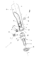
- the shaped gripping or supporting element subject of the invention is illustrated in Figure 1, where it is indicated as a whole by 1 , during application to a supporting structure S .
- the shaped element 1 is a handle applied to the supporting structure S, for example a door panel.
- the shaped element may constitute any supporting handle combined with a piece of furniture or a wall of a room of a building, or a supporting body, such as the rail in a bathroom of a living unit, for thin objects folded around it, for example towels.
- the shaped element 1 comprises:
- tubular body can be provided with one single end connected to the supporting structure.
- the construction form of the shaped element 1 will be described with reference to the shaped insert 7 only, connected to the tubular body 2 in correspondence with the end 2b , it being understood that the explanation also applies to the other shaped insert 6, connected to the end 2a of the tubular body 2.
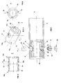
- the shaped element 1 comprises third fastening means consisting of the drawn-in edge 9 of a pair of first through holes 10, 11 obtained in the tubular body 2, the drawn-in edge 9 extending towards the inner surface 12a, 13a of two radial housings 12, 13 obtained in the shaped insert 7 and visible in greater detail in Figure 4.
- the shaped insert 7 consists of a tubular element 14, provided with a first end 14a through which the supporting element 4, which protrudes from the supporting structure S, is inserted in the tubular element 14.
- the radial housings 12, 13 are opposed, develop in a first longitudinal direction Y and are positioned symmetrically with respect to the longitudinal axis Z of the shaped insert 7.
- each of the radial housings 12, 13 consists of a second through hole, coaxial with the corresponding one of the first through holes 10, 11 obtained in the tubular body 2, made in the side wall 14c of the tubular element 14.
- the drawn-in edge 9 belonging to the first through holes 10, 11 of the tubular body 2 thus covers the inner surface 12a, 13a of the respective radial housings 12,13 .
- Figure 3 highlights the construction form of the shaped element 1 after the provision of a nut screw 18 on the drawn-in edge 9 which covers the inner surface 13a of the radial housing 13, and the inner surface of the first through hole 11.
- the radial housings can consist of blind holes obtained in the side wall of the shaped insert.
- Figure 2 highlights that they consist of a grub screw 17 which engages with the above-mentioned nut screw 18.
- the end 17a of the grub screw 17 is housed in an annular groove 19 obtained in the supporting element 4, delimited by slanting lateral surfaces 19a, 19b which force the end 17a of the grub screw 17 against the bottom 19c of the groove 19 when the grub screw 17 is inserted in the first through hole 11 and in the radial housing 13 to interlock the shaped insert 7 and the supporting element 4 .
- the lateral surfaces 19a, 19b of the annular groove 19 have an angle of 45°, particularly suitable for the function just described.
- the shaped element 1 comprises a plastic plug 20 , applied outside the grub screw 17 which otherwise, in application situations, would be undesirably visible.
- the plug 20 provides a continuous surface between the holed area and the outer surface 2c of the tubular body 2.
- the shaped element 1 comprises, furthermore, a wedge 21 pressed into the first through hole 10 and into the housing 12 opposite the one in which the grub screw 17 is inserted, intended to support on the outer surface 21a symbols, characters, wording, logos, trademarks or similar for identification purposes, affixed for example by screen-printing.
- the shaped element 1 comprises, furthermore, a seal gasket 22, preferably made of plastic, positioned adjacent to the shaped insert 7 and protruding from the tubular body 2, which purposely separates the tubular body 2 from the supporting structure S when it is applied to it.
- This construction solution is important when the shaped element 1 is combined with the supporting structure S, consisting as said of a panel, if this is made of material different from that of the tubular body 2, for example wood.
- the seal gasket 22 prevents the contact between the tubular body 2 made of steel and the supporting structure S made of wood from causing excess wear of the latter in the long term.
- Figures 5 and 6 illustrate, therefore, that the tubular element 14 has at a second end 14b a shoulder 15 where a notch 16 is obtained, which develops mainly according to a direction X square to the first longitudinal direction Y identified by the radial housings 12, 13, which acts as a reference in the connection phase between the shaped insert 7 and the tubular body 2.
- Figures 9 and 10 show a variant of the invention in which the shaped element, generically indicated by 100, differs from the previous one due to the type of radial housings in which the drawn-in edge 106 of the tubular body 101 extends inwards.
- Each housing 103, 104 consists of an annular recess 107, 108, more clearly visible in the detail of Figure 10, positioned at the level of the outer surface 105a of the tubular element 105 and obtained at the end of a second through hole 109, 110 made in the side wall 105b of the tubular element 105.
- the annular recess 107, 108 has a diameter D greater than the diameter d of the corresponding second through hole 109, 110.
- the difference between the diameter D of the annular recess 107, 108 and the diameter d of the second through hole 109, 110 is equal to the thickness of the drawn-in edge 106 of the tubular body 101.
- the nut screw 113 on which the grub screw 115 of the second fastening means, generically indicated by 114, will engage, is obtained on the drawn-in edge 106 which covers the inner surface of the annular recess 107 and on the inner surface of the second through hole 109.
- the solution featuring a shaped insert 6, 7 relative to the shaped element 1 is particularly suitable for tubular bodies with very small diameter, even 15 mm, while the solution relative to the shaped element 100 is suitable for tubular bodies with diameter of no less than 20 mm, for example 25, 30 or 35 mm, which are the diameters typically produced.
- the invention to be protected also refers to a method for the production of a shaped element of the type indicated above by 1 or 100 and comprising a tubular body 2 or 101 and a pair of shaped inserts, indicated for example by 6, 7 for the shaped element 1, which connect the tubular body 2 or 101 to a supporting structure S .
- the method comprises the following operations:
- the shaped inserts 6, 7 or 102 are connected to the respective tubular body 2 or 101 by pressure insertion.
- the insertion operation is performed by positioning the shaped inserts 6, 7 or 102 so as to arrange the housings 12, 13 or 103, 104 according to a first substantially vertical longitudinal direction Y.
- the shaped element subject of the invention in the construction forms described, has a very high load resistance, superior to that of equivalent known shaped elements.
- the machining work for drawing-in the edge can furthermore be performed more rapidly, by means of commonly used tools, than in the known technique.
- tubular body of the shaped gripping or supporting element available to the user can be produced in any thickness, since no threading is performed on the inner surface at its ends.
- the thickness of the tubular body can drop below said value, extending the range of tubular bodies that can be used for these types of applications and reducing the amount of material required, with evident savings on costs.
- the shaped element is lightened with respect to those carried out according to the known technique, a particularly important aspect in relation to the market preference for increasingly lightweight shaped elements.
- the invention furthermore enables the manufacturer to reduce production times and costs associated with the production of a shaped gripping or supporting element of the type previously described, since it simplifies the machining required.
- the tubular body may, in other applications, be combined with the supporting structure in a different way with respect to what is illustrated in the figures below, for example in a horizontal position.
- Punching of the tubular body will then be performed by arranging the tubular body in a vertical position, so that upon implementation the plug that covers the fastening grub screw and the wedge that closes the related through holes made in the tubular body and in the shaped insert are not directly visible.
- the material constituting the tubular body, the shaped insert and the supporting elements that can be combined with the supporting structure can be of the type known to a person skilled in the art.
- the second fastening means can be different from the grub screws described previously, without affecting the advantage offered by the present patent.
Landscapes
- Health & Medical Sciences (AREA)
- Public Health (AREA)
- Epidemiology (AREA)
- General Health & Medical Sciences (AREA)
- Mutual Connection Of Rods And Tubes (AREA)
- Piezo-Electric Or Mechanical Vibrators, Or Delay Or Filter Circuits (AREA)
- Moulding By Coating Moulds (AREA)
- Manipulator (AREA)
- Joining Of Building Structures In Genera (AREA)
- Prostheses (AREA)
- Casting Or Compression Moulding Of Plastics Or The Like (AREA)
Abstract
Description
- The invention described herein concerns a shaped gripping or supporting element and a method for the production of said shaped element.
- In particular, the shaped element for which patent rights are requested consists preferably of a handle applied to the panel of a door, a drawer or any supporting structure, without excluding the possibility of application on furnishing elements such as, for example, towel rails of a bathroom of a living unit or other building.
- As is known, handles consist of a shaped tubular body fixed by at least one end to a supporting structure, consisting for example of the panel of a door or a wall of a room of any building.
- The present invention concerns in particular the type of handles in which the tubular body is made of metal, for example steel.
- The tubular body, shaped so as to permit a comfortable safe grip by the user, has in cross section profiles of different shape, usually circular with diameters varying from 20 to 35 mm.
- The thickness of the tubular body, for reasons which will be better explained below, is never less than 2 mm, generally in the
range 2÷4 mm. - According to the most widespread known technique, the tubular body is combined with the supporting structure via connection means which consist essentially of an insert, inserted at the end of the tubular body, which is positioned adjacent to the supporting structure, and of a corresponding supporting element, commonly called "bush", protruding from the supporting structure to which it is fixed via fastening means of the known type, for example a screw that engages in a rawl plug pressed into the supporting structure.
- To complete the application and give the coupling between tubular body and supporting structure greater stability, further screw fastening means are provided, consisting for example of a grub screw inserted in coaxial through holes obtained in the tubular body and in the insert, stopping against the outer wall of the bush.
- The shaped elements described above have some recognised drawbacks, however.
- The main drawback is constituted by the fact that the coupling between insert and tubular body is obtained via screw means.
- In fact, the tubular body has on its inner walls of each end a nut screw with which a screw obtained on the outer surface of the insert engages.
- The provision of said screw means on the insert and on the tubular body increases the complexity of the machining required to obtain the shaped element, with consequent increase in production times and costs.
- A second drawback is due to the fact that, to obtain the nut screw, the thickness of the tubular body must be no less than a certain value, 2 mm as said.
- Therefore, the weight of the tubular body, although increasingly lightweight in modern solutions, does not drop below certain values dictated by production requirements.
- Said aspect is of no small significance, in the light of the market tendency towards increasingly lightweight handles.
- A further drawback derives from the fact that in the long term the screw means, due to their specific function, and being under the continuous grip of the shaped element, cause a certain play between the tubular body and the insert, thus loosening and affecting even only partly the stability of the coupling between these components.
- The present invention intends to overcome the above-mentioned drawbacks.
- In further detail, the main aim of the present invention is to provide a shaped gripping or supporting element that is simpler than equivalent shaped elements of known type.
- A second aim of the invention is to reduce the times and costs associated with the production of a shaped gripping or supporting element with respect to the known art.
- A further aim is to produce shaped gripping or supporting elements that are thinner than the shaped elements of the known type, thus making available, consequently, with the same diameter, shaped supporting or gripping elements that are lighter than those produced according to the known art.
- Last but not least, a further aim of the invention is to obtain a coupling between the inserts and the tubular body of a shaped gripping or supporting element that is more stable and resistant in the long term compared to the shaped elements currently available on the market.
- Said aims have been achieved through the implementation of a shaped gripping or supporting element which, in accordance with the contents of the first claim, comprises:
- a shaped tubular body provided with at least one end suited to be connected to a supporting structure;
- at least one supporting element suited to be applied to said supporting structure via first fastening means which protrude from the outer surface of said supporting structure;
- at least one shaped insert, inserted in said end of said tubular body, suited to be combined with said supporting element when said tubular body is positioned adjacent to said supporting structure;
- second fastening means suitable for connecting in a stable manner said tubular body and said supporting element,
- The subject of the present invention is also a method for the production of a shaped element of the type comprising a shaped tubular body and at least one shaped insert that connects said tubular body to a supporting structure which, in accordance with the corresponding main claim, is characterised in that it comprises the following operations:
- making said tubular body;
- making said shaped insert;
- making one or more radial housings in said shaped insert;
- coupling said shaped insert with said tubular body;
- punching said tubular body at the level of said radial housings to obtain in said tubular body at least one first through hole, the drawn-in edge of which extends towards the inner surface of said housings.
- Advantageously, the shaped gripping or supporting element subject of the invention is simpler to produce than the elements carried out according to the known art.
- Again advantageously, the shaped element of the invention is produced more quickly than in the known art, with consequent advantages in terms of resulting costs for the producer.
- Again advantageously, the invention concerns the production of particularly thin shaped gripping or supporting elements, thinner than those produced according to the known art.
- This results in the advantage of lightening some shaped gripping or supporting elements, an aspect that will be more attractive for market operators.
- In an advantageous manner, furthermore, the invention determines a particularly effective connection between the shaped insert and the tubular body, stable and long-lasting, less subject to wear or breakage than equivalent shaped elements of the known type.
- This is achieved by eliminating from the shaped inserts and the tubular body the screw means used in the known art most similar to the invention, and by adopting a connection system based on drawing-in of the tubular body towards the inner walls of housings obtained in the shaped insert, with high load resistance.
- Experimental tests performed in an engineering workshop have shown that the shaped element of the invention bears considerable loads, in the order of 1,200 N/mm2.
- The aims and advantages described above, and others which will be better specified in the course of the present patent, will be highlighted in greater detail in the description of preferred embodiments of the invention provided as a guide, with reference to the attached drawings, wherein:
- Figure 1 is an exploded axonometric view of the shaped element of the invention during application to a supporting structure;
- Figure 2 is a partially sectioned axonometric view of the tubular body of Figure 1;
- Figure 3 shows a sectioned detail of Figure 2;
- Figure 4 shows an enlarged detail of Figure 3;
- Figure 5 is an axonometric view of the detail shown in Figure 4;
- Figure 6 is the front view of Figure 5;
- Figure 7 is an axonometric view of the drawing-in operation of the method of the invention;
- Figure 8 is an axonometric view of the connection operation of the method of the invention;
- Figure 9 shows a variant of Figure 3;
- Figure 10 shows a detail of Figure 9.
- The shaped gripping or supporting element subject of the invention is illustrated in Figure 1, where it is indicated as a whole by 1, during application to a supporting structure S.
- In this case, the
shaped element 1 is a handle applied to the supporting structure S, for example a door panel. - It is understood, however, that in further embodiments of the invention the shaped element may constitute any supporting handle combined with a piece of furniture or a wall of a room of a building, or a supporting body, such as the rail in a bathroom of a living unit, for thin objects folded around it, for example towels.
- As can be seen in Figure 1, the
shaped element 1 comprises: - a shaped
tubular body 2, preferably made of metal, for example steel, provided withends - a pair of supporting
elements 3, 4, also made of metal, applied to the supporting structure S via first fastening means, indicated as a whole by 5 and of the type known to a person skilled in the art, which protrude from the outer surface S e of the supporting structure S; - a pair of
shaped inserts corresponding end tubular body 2, designed to be coupled with the corresponding element of the supportingelements 3, 4 when thetubular body 2 is positioned adjacent to the supporting structure S; - second fastening means, indicated as a whole by 8, used to connect in a stable manner the
tubular body 2 and the supportingelements 3, 4. - It should be noted that in other embodiments of the invention the tubular body can be provided with one single end connected to the supporting structure. Below, for the sake of convenience and in accordance with the contents of Figures from 2 to 6, the construction form of the
shaped element 1 will be described with reference to theshaped insert 7 only, connected to thetubular body 2 in correspondence with theend 2b, it being understood that the explanation also applies to the othershaped insert 6, connected to theend 2a of thetubular body 2. - According to the invention, the
shaped element 1 comprises third fastening means consisting of the drawn-inedge 9 of a pair of first throughholes tubular body 2, the drawn-inedge 9 extending towards theinner surface radial housings shaped insert 7 and visible in greater detail in Figure 4. - The
shaped insert 7 consists of atubular element 14, provided with afirst end 14a through which the supporting element 4, which protrudes from the supporting structure S, is inserted in thetubular element 14. - The
radial housings shaped insert 7. - According to the preferred embodiment described herein, each of the
radial housings holes tubular body 2, made in theside wall 14c of thetubular element 14. - The drawn-in
edge 9 belonging to the first throughholes tubular body 2 thus covers theinner surface radial housings - The construction detail just described can be clearly seen in Figure 3, which highlights the construction form of the shaped
element 1 after the provision of anut screw 18 on the drawn-inedge 9 which covers theinner surface 13a of theradial housing 13, and the inner surface of the first throughhole 11. - In accordance with other embodiments of the invention, the radial housings can consist of blind holes obtained in the side wall of the shaped insert.
- As regards the second fastening means 8, Figure 2 highlights that they consist of a
grub screw 17 which engages with the above-mentionednut screw 18. - In further detail, the
end 17a of thegrub screw 17 is housed in anannular groove 19 obtained in the supporting element 4, delimited by slantinglateral surfaces end 17a of thegrub screw 17 against the bottom 19c of thegroove 19 when thegrub screw 17 is inserted in the first throughhole 11 and in theradial housing 13 to interlock the shapedinsert 7 and the supporting element 4. - Preferably but not necessarily, the
lateral surfaces annular groove 19 have an angle of 45°, particularly suitable for the function just described. - Again in Figure 2 it can be seen that the shaped
element 1 comprises aplastic plug 20, applied outside thegrub screw 17 which otherwise, in application situations, would be undesirably visible. - The
plug 20 provides a continuous surface between the holed area and theouter surface 2c of thetubular body 2. - The shaped
element 1 comprises, furthermore, awedge 21 pressed into the first throughhole 10 and into thehousing 12 opposite the one in which thegrub screw 17 is inserted, intended to support on theouter surface 21a symbols, characters, wording, logos, trademarks or similar for identification purposes, affixed for example by screen-printing. - The shaped
element 1 comprises, furthermore, aseal gasket 22, preferably made of plastic, positioned adjacent to the shapedinsert 7 and protruding from thetubular body 2, which purposely separates thetubular body 2 from the supporting structure S when it is applied to it. - This construction solution is important when the shaped
element 1 is combined with the supporting structure S, consisting as said of a panel, if this is made of material different from that of thetubular body 2, for example wood. - The
seal gasket 22 prevents the contact between thetubular body 2 made of steel and the supporting structure S made of wood from causing excess wear of the latter in the long term. - Figures 5 and 6 illustrate, therefore, that the
tubular element 14 has at asecond end 14b ashoulder 15 where anotch 16 is obtained, which develops mainly according to a direction X square to the first longitudinal direction Y identified by theradial housings shaped insert 7 and thetubular body 2. - Figures 9 and 10 show a variant of the invention in which the shaped element, generically indicated by 100, differs from the previous one due to the type of radial housings in which the drawn-in
edge 106 of thetubular body 101 extends inwards. - Each
housing annular recess outer surface 105a of thetubular element 105 and obtained at the end of a second throughhole side wall 105b of thetubular element 105. - The
annular recess hole - The difference between the diameter D of the
annular recess hole edge 106 of thetubular body 101. - In this case, the
nut screw 113, on which thegrub screw 115 of the second fastening means, generically indicated by 114, will engage, is obtained on the drawn-inedge 106 which covers the inner surface of theannular recess 107 and on the inner surface of the second throughhole 109. - The solution featuring a
shaped insert element 1 is particularly suitable for tubular bodies with very small diameter, even 15 mm, while the solution relative to the shapedelement 100 is suitable for tubular bodies with diameter of no less than 20 mm, for example 25, 30 or 35 mm, which are the diameters typically produced. - The invention to be protected also refers to a method for the production of a shaped element of the type indicated above by 1 or 100 and comprising a
tubular body element 1, which connect thetubular body - According to the invention, the method comprises the following operations:
- making the
tubular body - making the shaped
inserts - making in the shaped
inserts radial housings - coupling the shaped
inserts tubular body - punching the
tubular body radial housings tubular body 2 or 101 a pair of first throughholes edge inner surface housings
The method comprises, furthermore, a threading operation of the drawn-inedge 9 and, in the case of the shapedelement 100, of the drawn-inedge 106 and of the second throughhole 109 obtained in the shapedinsert 102, performed after the punching of thetubular body tubular body - The shaped inserts 6, 7 or 102 are connected to the respective
tubular body - The insertion operation is performed by positioning the shaped
inserts housings - This is aimed to permit punching to be performed with a tool that operates in a vertical direction according to the manufacturer's needs.
- The shaped element subject of the invention, in the construction forms described, has a very high load resistance, superior to that of equivalent known shaped elements.
- This is obtained by providing on the tubular body a drawn-in edge which extends into radial housings obtained in the shaped inserts.
- The machining work for drawing-in the edge can furthermore be performed more rapidly, by means of commonly used tools, than in the known technique.
- The coupling between shaped inserts and tubular body does not use screw means, typical of the known art, which unnecessarily complicate construction of the shaped element.
- Moreover, the tubular body of the shaped gripping or supporting element available to the user can be produced in any thickness, since no threading is performed on the inner surface at its ends.
- Since the shaped elements of the known type make use of screw means, they require the tubular body thickness to be no less than 2 mm, otherwise it is impossible to perform the threading operation.
- Via the invention, the thickness of the tubular body can drop below said value, extending the range of tubular bodies that can be used for these types of applications and reducing the amount of material required, with evident savings on costs.
- Consequently, the shaped element is lightened with respect to those carried out according to the known technique, a particularly important aspect in relation to the market preference for increasingly lightweight shaped elements.
- The invention furthermore enables the manufacturer to reduce production times and costs associated with the production of a shaped gripping or supporting element of the type previously described, since it simplifies the machining required.
- On the basis of the above, it can be seen that the shaped gripping or supporting element of the invention and the related embodiment method achieve the objectives and offer the advantages mentioned previously.
- Upon implementation, modifications may be made to the shaped element of the invention consisting, for example, in different forms and dimensions of the tubular body.
- The tubular body may, in other applications, be combined with the supporting structure in a different way with respect to what is illustrated in the figures below, for example in a horizontal position.
- Punching of the tubular body will then be performed by arranging the tubular body in a vertical position, so that upon implementation the plug that covers the fastening grub screw and the wedge that closes the related through holes made in the tubular body and in the shaped insert are not directly visible.
- In addition to this, the material constituting the tubular body, the shaped insert and the supporting elements that can be combined with the supporting structure can be of the type known to a person skilled in the art.
- Furthermore, the second fastening means can be different from the grub screws described previously, without affecting the advantage offered by the present patent.
- All the changes described and referred to, but not shown in the attached drawings, must be considered protected by the present patent, provided that they come under the scope of the following claims.
Claims (23)
- Shaped gripping or supporting element (1; 100) comprising:- a shaped tubular body (2; 101) provided with at least one end (2a, 2b) suited to be connected to a supporting structure (S);- at least one supporting element (3, 4), suited to be applied to said supporting structure (S) by means of first fastening means (5) which protrude from the outer surface (Se) of said supporting structure (S);- at least one shaped insert (6, 7; 102), inserted in said end (2a, 2b) of said tubular body (2; 101), suited to be connected to said supporting element (3, 4) when said tubular body (2; 101) is positioned adjacent to said supporting structure (S);- second fastening means (8; 114) suited to connect in a stable manner said tubular body (2; 101) and said supporting element (3, 4),characterised in that it comprises third fastening means consisting of the drawn-in edge (9; 106) of at least one first through hole (10, 11; 111, 112) obtained in said tubular body (2; 101), said drawn-in edge (9; 106) extending towards the inner surface (12a, 13a) of one or more radial housings (12, 13; 103, 104) obtained in said shaped insert (6, 7; 102).
- Element (1; 100) according to claim 1), characterised in that said shaped insert (6, 7; 102) comprises two opposed radial housings (12, 13; 103, 104), which develop according to a first longitudinal direction (Y), arranged symmetrically with respect to the longitudinal axis (Z) of said shaped insert (6, 7; 102).
- Element (1; 100) according to claim 2), characterised in that said shaped insert (6, 7; 102) consists of a tubular element (14; 105) provided with a first end (14a) through which said supporting element (3, 4) is inserted in said tubular element (14; 105).
- Element (1) according to claim 3), characterised in that each of said radial housings (12, 13) consists of a second through hole, coaxial with said first through hole (10, 11), made in the side wall (14c) of said tubular element (14).
- Element (1) according to claim 4), characterised in that said drawn-in edge (9) covers said inner surface (12a, 13a) of said radial housing (12, 13).
- Element (100) according to claim 3), characterised in that each of said radial housings (103, 104) consists of an annular recess (107, 108), obtained at the level of the outer surface (105a) of said tubular element (105) and arranged at the end of a second through hole (109, 110), coaxial with said first through hole, made in the side wall (105b) of said tubular element (105).
- Element (100) according to claim 6), characterised in that said annular recess (107, 108) has a diameter (D) greater than the diameter (d) of said second through hole (109, 110).
- Element (100) according to claim 7), characterised in that the difference between said diameter (D) of said annular recess (107, 108) and said diameter (d) of said second through hole (109, 110) is equal to the thickness of said drawn-in edge (106) of said tubular body (101).
- Element (1; 100) according to claim 3), characterised in that said tubular element (14; 105) has at a second end (14b) a shoulder (15) in which a notch (16) is obtained, which develops mainly according to a direction (X) square to said first longitudinal direction (Y) identified by said radial housings (12, 13; 103, 104), suited to constitute a reference for the insertion of said shaped insert (6, 7; 102) in said tubular body (2; 101).
- Element (1) according to claim 1), characterised in that said second fastening means (8) consist of a grub screw (17) which engages with a nut screw (18) obtained on said drawn-in edge which covers said inner surface (12a, 12b) of at least one of said housings (12, 13).
- Element (100) according to claim 1), characterised in that said second fastening means (114) consist of a grub screw (115) which engages with a nut screw (113) obtained on said drawn-in edge (106) which covers said inner surface of said annular recess (107) of at least one of said housings (103, 104).
- Element (1; 100) according to claim 10) or 11), characterised in that the end (17a) of said grub screw (17; 115) is housed in an annular groove (19) obtained in said supporting element (3, 4), delimited by slanting lateral surfaces (19a, 19b) that force said end (17a) of said grub screw (17; 115) against the bottom (19c) of said groove (19) when said grub screw (17; 115) is inserted in said first through hole (11; 112) and in at least one of said housings (12, 13; 103, 104) to interlock said shaped insert (6, 7; 102) and said supporting element (3, 4).
- Element (1; 100) according to claim 12), characterised in that said lateral surfaces (19a, 19b) of said annular groove (19) have an angle of 45°.
- Element (1; 100) according to claim 10) or 11), characterised in that it comprises a plug (20) applied externally to said grub screw (17; 115).
- Element (1; 100) according to claim 10) or 11), characterised in that it comprises a wedge (21), inserted in said first though hole (10; 111) and in one of said housings (12, 13; 103; 104) opposite the one in which said grub screw (17; 115) is inserted, suited to support on the outer surface (21a) symbols, characters, wording, logos, trademarks or similar for identification purposes.
- Element (1; 100) according to claim 1), characterised in that it comprises a seal gasket (22), arranged adjacent to said shaped insert (6, 7; 102) and protruding from said tubular body (2; 101), suited to separate said tubular body (2; 101) from said supporting structure (S) when they are adjacent to each other.
- Method for the production of a shaped gripping or supporting element (1; 100) of the type comprising a shaped tubular body (2; 101) and at least one shaped insert (6, 7; 102) which connects said tubular body (2; 101) to a supporting structure (S), characterised in that it comprises the following operations:- making said tubular body (2; 101);- making said shaped insert (6, 7; 102);- making in said shaped insert (6, 7; 102) one or more radial housings (12, 13; 103, 104);- coupling said shaped insert (6, 7; 102) with said tubular body (2; 101);- punching said tubular body (2; 101) at the level of said radial housings (12, 13; 103, 104) to obtain in said tubular body (2) at least one first through hole (10, 11; 111, 112) the drawn-in edge of which (9; 106) extends towards the inner surface (12a, 13a) of said housings (12, 13; 103, 104).
- Method according to claim 17), characterised in that it comprises a threading operation of said drawn-in edge (9), performed after said punching operation of said tubular body (2), to permit the application of second fastening means (8) suited to lock in a stable manner said tubular body (2) to said supporting structure (S).
- Method according to claim 17), characterised in that it comprises a threading operation of said drawn-in edge (106) and at least one second through hole (109) obtained in said shaped insert (102), performed after said punching operation of said tubular body (101), to permit the application of second fastening means (114) suited to lock in a stable manner said tubular body (101) to said supporting structure.
- Method according to claim 17), characterised in that said operation for connecting said shaped insert (6, 7; 102) to said tubular body (2; 101) is a pressure insertion.
- Method according to claim 17), characterised in that said operation for connecting said shaped insert (6, 7; 102) to said tubular body (2; 101) is performed by positioning said shaped insert (6, 7; 102) arranging said housings (12, 13; 103, 104) according to a first substantially vertical longitudinal direction (Y).
- Method according to claim 17), characterised in that said drawn-in edge (9) covers said inner surface (12a, 13a) of said housings (12, 13) when the diameter of said tubular body (2) does not exceed 20 mm.
- Method according to claim 17), characterised in that said drawn-in edge (106) is housed in an annular recess (107, 108) positioned at the level of the outer surface of said shaped insert (102) when the diameter of said tubular body (101) exceeds 20 mm.
Applications Claiming Priority (1)
| Application Number | Priority Date | Filing Date | Title |
|---|---|---|---|
| IT000260A ITVI20040260A1 (en) | 2004-11-10 | 2004-11-10 | SAGOMATO ELEMENT OF GRIP OR SUPPORT AND METHOD FOR THE REALIZATION OF SUCH A SHAPED ELEMENT |
Publications (3)
| Publication Number | Publication Date |
|---|---|
| EP1656868A2 true EP1656868A2 (en) | 2006-05-17 |
| EP1656868A3 EP1656868A3 (en) | 2007-03-07 |
| EP1656868B1 EP1656868B1 (en) | 2008-10-08 |
Family
ID=35798484
Family Applications (1)
| Application Number | Title | Priority Date | Filing Date |
|---|---|---|---|
| EP05110482A Active EP1656868B1 (en) | 2004-11-10 | 2005-11-08 | Shaped gripping or supporting element and method for producing said shaped element. |
Country Status (4)
| Country | Link |
|---|---|
| EP (1) | EP1656868B1 (en) |
| AT (1) | ATE410109T1 (en) |
| DE (1) | DE602005010184D1 (en) |
| IT (1) | ITVI20040260A1 (en) |
Cited By (7)
| Publication number | Priority date | Publication date | Assignee | Title |
|---|---|---|---|---|
| JP2008148983A (en) * | 2006-12-19 | 2008-07-03 | Toto Ltd | Handrail |
| GB2457379A (en) * | 2008-02-18 | 2009-08-19 | Liberty Hardware Mfg Corp | Sealing arrangement for bath bar |
| GB2457793A (en) * | 2008-02-26 | 2009-09-02 | Liberty Hardware Mfg Corp | Grab bar assembly |
| WO2014054000A1 (en) * | 2012-10-02 | 2014-04-10 | Andrew Keith Maclaren-Taylor | A mounting arrangement for mounting an accessory to a surface |
| WO2014189688A1 (en) * | 2013-05-20 | 2014-11-27 | Electrolux Home Products, Inc. | Handle mounting insert |
| US9220340B2 (en) * | 2014-01-02 | 2015-12-29 | Anthony KUO | Bathroom shelf assembly and bathroom shelf having the same |
| US9351572B2 (en) | 2014-01-02 | 2016-05-31 | Anthony KUO | Bathroom shelf assembly and bathroom shelf having the same |
Citations (3)
| Publication number | Priority date | Publication date | Assignee | Title |
|---|---|---|---|---|
| DE3518127A1 (en) * | 1985-05-21 | 1986-12-18 | Hans Grimberg Edelstahl GmbH, 4300 Essen | Handgrip-fastening system |
| US5810502A (en) * | 1995-01-18 | 1998-09-22 | Hoppe Ag | Screw fastener |
| DE10103243C1 (en) * | 2001-01-25 | 2002-10-02 | Kaldewei Franz Gmbh & Co | Connection system for use with bowl or basin forming part of sanitary ware uses movable shoe on underside of bowl, with pin sealing disc and tensioning element |
-
2004
- 2004-11-10 IT IT000260A patent/ITVI20040260A1/en unknown
-
2005
- 2005-11-08 EP EP05110482A patent/EP1656868B1/en active Active
- 2005-11-08 AT AT05110482T patent/ATE410109T1/en not_active IP Right Cessation
- 2005-11-08 DE DE602005010184T patent/DE602005010184D1/en active Active
Patent Citations (3)
| Publication number | Priority date | Publication date | Assignee | Title |
|---|---|---|---|---|
| DE3518127A1 (en) * | 1985-05-21 | 1986-12-18 | Hans Grimberg Edelstahl GmbH, 4300 Essen | Handgrip-fastening system |
| US5810502A (en) * | 1995-01-18 | 1998-09-22 | Hoppe Ag | Screw fastener |
| DE10103243C1 (en) * | 2001-01-25 | 2002-10-02 | Kaldewei Franz Gmbh & Co | Connection system for use with bowl or basin forming part of sanitary ware uses movable shoe on underside of bowl, with pin sealing disc and tensioning element |
Cited By (9)
| Publication number | Priority date | Publication date | Assignee | Title |
|---|---|---|---|---|
| JP2008148983A (en) * | 2006-12-19 | 2008-07-03 | Toto Ltd | Handrail |
| GB2457379A (en) * | 2008-02-18 | 2009-08-19 | Liberty Hardware Mfg Corp | Sealing arrangement for bath bar |
| GB2457379B (en) * | 2008-02-18 | 2012-12-05 | Liberty Hardware Mfg Corp | Sealing arrangement for bath bar |
| GB2457793A (en) * | 2008-02-26 | 2009-09-02 | Liberty Hardware Mfg Corp | Grab bar assembly |
| WO2014054000A1 (en) * | 2012-10-02 | 2014-04-10 | Andrew Keith Maclaren-Taylor | A mounting arrangement for mounting an accessory to a surface |
| WO2014189688A1 (en) * | 2013-05-20 | 2014-11-27 | Electrolux Home Products, Inc. | Handle mounting insert |
| US9297182B2 (en) | 2013-05-20 | 2016-03-29 | Electrolux Home Products, Inc. | Handle mounting insert |
| US9220340B2 (en) * | 2014-01-02 | 2015-12-29 | Anthony KUO | Bathroom shelf assembly and bathroom shelf having the same |
| US9351572B2 (en) | 2014-01-02 | 2016-05-31 | Anthony KUO | Bathroom shelf assembly and bathroom shelf having the same |
Also Published As
| Publication number | Publication date |
|---|---|
| DE602005010184D1 (en) | 2008-11-20 |
| ATE410109T1 (en) | 2008-10-15 |
| EP1656868A3 (en) | 2007-03-07 |
| EP1656868B1 (en) | 2008-10-08 |
| ITVI20040260A1 (en) | 2005-02-10 |
Similar Documents
| Publication | Publication Date | Title |
|---|---|---|
| EP1656868B1 (en) | Shaped gripping or supporting element and method for producing said shaped element. | |
| EP3325820B1 (en) | Channel lock fasteners and fastening system | |
| CN108138825B (en) | Coupling device with wide accessibility for components of furniture and household articles | |
| US20100139046A1 (en) | Pull assembly | |
| CA1277898C (en) | Tubular chair leg formed for direct mounting of caster or glide | |
| US20070284324A1 (en) | Inside Wall Mounted Hanging Rods | |
| WO2007133955A2 (en) | Flexible and extendable drill bit assembly | |
| WO2001020176A1 (en) | Screw connection | |
| US2594027A (en) | Mounting stud for drawer pull handles | |
| EP1695647A2 (en) | Gripping or supporting element. | |
| AU2002216999A1 (en) | Bushing for fixing a fitting to a hollow profile which is provided with a projecting profiled part | |
| DE102005061802A1 (en) | Domestic appliance with a handle and a movable part and handle | |
| US9655483B2 (en) | Grab bar with insert | |
| IT201800004262A1 (en) | GROUP-HANDLE WITHOUT SCREWS FOR ONE DOOR | |
| US4416320A (en) | Ladder tape roll for venetian blinds | |
| EP2020475A1 (en) | Adjustable hinge for doors and windows | |
| EP2009206B1 (en) | Fixing element for fixing a hinge to the jamb of a door or window frame or the like | |
| JP3118499U (en) | Shelf support column | |
| KR200492848Y1 (en) | Hookup fixings toilet seat cover | |
| EP3109577B1 (en) | Domestic appliance | |
| EP3153718B1 (en) | Joining device with compact leveller for parts of furniture and furnishing items | |
| EP0708260B1 (en) | Fastening and joining means | |
| EP3974663A1 (en) | Attachment system between two components | |
| KR200429053Y1 (en) | Bolt for handle | |
| KR200279908Y1 (en) | handle for furniture |
Legal Events
| Date | Code | Title | Description |
|---|---|---|---|
| PUAI | Public reference made under article 153(3) epc to a published international application that has entered the european phase |
Free format text: ORIGINAL CODE: 0009012 |
|
| AK | Designated contracting states |
Kind code of ref document: A2 Designated state(s): AT BE BG CH CY CZ DE DK EE ES FI FR GB GR HU IE IS IT LI LT LU LV MC NL PL PT RO SE SI SK TR |
|
| AX | Request for extension of the european patent |
Extension state: AL BA HR MK YU |
|
| PUAL | Search report despatched |
Free format text: ORIGINAL CODE: 0009013 |
|
| AK | Designated contracting states |
Kind code of ref document: A3 Designated state(s): AT BE BG CH CY CZ DE DK EE ES FI FR GB GR HU IE IS IT LI LT LU LV MC NL PL PT RO SE SI SK TR |
|
| AX | Request for extension of the european patent |
Extension state: AL BA HR MK YU |
|
| RAP1 | Party data changed (applicant data changed or rights of an application transferred) |
Owner name: M.P.M. SNC DI MALINI PRIMO & C. |
|
| RIC1 | Information provided on ipc code assigned before grant |
Ipc: A47B 95/02 20060101ALI20070131BHEP Ipc: A47K 10/10 20060101AFI20060227BHEP Ipc: E05B 1/00 20060101ALI20070131BHEP Ipc: A47K 17/02 20060101ALI20070131BHEP |
|
| RIN1 | Information on inventor provided before grant (corrected) |
Inventor name: MALINI, PRIMO ROBERTO |
|
| 17P | Request for examination filed |
Effective date: 20070906 |
|
| AKX | Designation fees paid |
Designated state(s): AT BE BG CH CY CZ DE DK EE ES FI FR GB GR HU IE IS IT LI LT LU LV MC NL PL PT RO SE SI SK TR |
|
| GRAP | Despatch of communication of intention to grant a patent |
Free format text: ORIGINAL CODE: EPIDOSNIGR1 |
|
| GRAS | Grant fee paid |
Free format text: ORIGINAL CODE: EPIDOSNIGR3 |
|
| GRAA | (expected) grant |
Free format text: ORIGINAL CODE: 0009210 |
|
| AK | Designated contracting states |
Kind code of ref document: B1 Designated state(s): AT BE BG CH CY CZ DE DK EE ES FI FR GB GR HU IE IS IT LI LT LU LV MC NL PL PT RO SE SI SK TR |
|
| REG | Reference to a national code |
Ref country code: GB Ref legal event code: FG4D |
|
| REG | Reference to a national code |
Ref country code: CH Ref legal event code: EP |
|
| REG | Reference to a national code |
Ref country code: IE Ref legal event code: FG4D |
|
| REF | Corresponds to: |
Ref document number: 602005010184 Country of ref document: DE Date of ref document: 20081120 Kind code of ref document: P |
|
| PG25 | Lapsed in a contracting state [announced via postgrant information from national office to epo] |
Ref country code: SI Free format text: LAPSE BECAUSE OF FAILURE TO SUBMIT A TRANSLATION OF THE DESCRIPTION OR TO PAY THE FEE WITHIN THE PRESCRIBED TIME-LIMIT Effective date: 20081008 |
|
| NLV1 | Nl: lapsed or annulled due to failure to fulfill the requirements of art. 29p and 29m of the patents act | ||
| PG25 | Lapsed in a contracting state [announced via postgrant information from national office to epo] |
Ref country code: LT Free format text: LAPSE BECAUSE OF FAILURE TO SUBMIT A TRANSLATION OF THE DESCRIPTION OR TO PAY THE FEE WITHIN THE PRESCRIBED TIME-LIMIT Effective date: 20081008 Ref country code: ES Free format text: LAPSE BECAUSE OF FAILURE TO SUBMIT A TRANSLATION OF THE DESCRIPTION OR TO PAY THE FEE WITHIN THE PRESCRIBED TIME-LIMIT Effective date: 20090119 Ref country code: BG Free format text: LAPSE BECAUSE OF FAILURE TO SUBMIT A TRANSLATION OF THE DESCRIPTION OR TO PAY THE FEE WITHIN THE PRESCRIBED TIME-LIMIT Effective date: 20090108 Ref country code: AT Free format text: LAPSE BECAUSE OF FAILURE TO SUBMIT A TRANSLATION OF THE DESCRIPTION OR TO PAY THE FEE WITHIN THE PRESCRIBED TIME-LIMIT Effective date: 20081008 |
|
| PG25 | Lapsed in a contracting state [announced via postgrant information from national office to epo] |
Ref country code: FI Free format text: LAPSE BECAUSE OF FAILURE TO SUBMIT A TRANSLATION OF THE DESCRIPTION OR TO PAY THE FEE WITHIN THE PRESCRIBED TIME-LIMIT Effective date: 20081008 Ref country code: PL Free format text: LAPSE BECAUSE OF FAILURE TO SUBMIT A TRANSLATION OF THE DESCRIPTION OR TO PAY THE FEE WITHIN THE PRESCRIBED TIME-LIMIT Effective date: 20081008 Ref country code: LV Free format text: LAPSE BECAUSE OF FAILURE TO SUBMIT A TRANSLATION OF THE DESCRIPTION OR TO PAY THE FEE WITHIN THE PRESCRIBED TIME-LIMIT Effective date: 20081008 Ref country code: IS Free format text: LAPSE BECAUSE OF FAILURE TO SUBMIT A TRANSLATION OF THE DESCRIPTION OR TO PAY THE FEE WITHIN THE PRESCRIBED TIME-LIMIT Effective date: 20090208 Ref country code: PT Free format text: LAPSE BECAUSE OF FAILURE TO SUBMIT A TRANSLATION OF THE DESCRIPTION OR TO PAY THE FEE WITHIN THE PRESCRIBED TIME-LIMIT Effective date: 20090218 Ref country code: NL Free format text: LAPSE BECAUSE OF FAILURE TO SUBMIT A TRANSLATION OF THE DESCRIPTION OR TO PAY THE FEE WITHIN THE PRESCRIBED TIME-LIMIT Effective date: 20081008 |
|
| PG25 | Lapsed in a contracting state [announced via postgrant information from national office to epo] |
Ref country code: MC Free format text: LAPSE BECAUSE OF NON-PAYMENT OF DUE FEES Effective date: 20081130 |
|
| PG25 | Lapsed in a contracting state [announced via postgrant information from national office to epo] |
Ref country code: EE Free format text: LAPSE BECAUSE OF FAILURE TO SUBMIT A TRANSLATION OF THE DESCRIPTION OR TO PAY THE FEE WITHIN THE PRESCRIBED TIME-LIMIT Effective date: 20081008 Ref country code: DK Free format text: LAPSE BECAUSE OF FAILURE TO SUBMIT A TRANSLATION OF THE DESCRIPTION OR TO PAY THE FEE WITHIN THE PRESCRIBED TIME-LIMIT Effective date: 20081008 Ref country code: RO Free format text: LAPSE BECAUSE OF FAILURE TO SUBMIT A TRANSLATION OF THE DESCRIPTION OR TO PAY THE FEE WITHIN THE PRESCRIBED TIME-LIMIT Effective date: 20081008 Ref country code: BE Free format text: LAPSE BECAUSE OF FAILURE TO SUBMIT A TRANSLATION OF THE DESCRIPTION OR TO PAY THE FEE WITHIN THE PRESCRIBED TIME-LIMIT Effective date: 20081008 |
|
| PLBE | No opposition filed within time limit |
Free format text: ORIGINAL CODE: 0009261 |
|
| STAA | Information on the status of an ep patent application or granted ep patent |
Free format text: STATUS: NO OPPOSITION FILED WITHIN TIME LIMIT |
|
| REG | Reference to a national code |
Ref country code: IE Ref legal event code: MM4A |
|
| PG25 | Lapsed in a contracting state [announced via postgrant information from national office to epo] |
Ref country code: SE Free format text: LAPSE BECAUSE OF FAILURE TO SUBMIT A TRANSLATION OF THE DESCRIPTION OR TO PAY THE FEE WITHIN THE PRESCRIBED TIME-LIMIT Effective date: 20090108 Ref country code: CZ Free format text: LAPSE BECAUSE OF FAILURE TO SUBMIT A TRANSLATION OF THE DESCRIPTION OR TO PAY THE FEE WITHIN THE PRESCRIBED TIME-LIMIT Effective date: 20081008 |
|
| 26N | No opposition filed |
Effective date: 20090709 |
|
| PG25 | Lapsed in a contracting state [announced via postgrant information from national office to epo] |
Ref country code: SK Free format text: LAPSE BECAUSE OF FAILURE TO SUBMIT A TRANSLATION OF THE DESCRIPTION OR TO PAY THE FEE WITHIN THE PRESCRIBED TIME-LIMIT Effective date: 20081008 |
|
| PG25 | Lapsed in a contracting state [announced via postgrant information from national office to epo] |
Ref country code: IE Free format text: LAPSE BECAUSE OF NON-PAYMENT OF DUE FEES Effective date: 20081108 |
|
| REG | Reference to a national code |
Ref country code: CH Ref legal event code: PL |
|
| GBPC | Gb: european patent ceased through non-payment of renewal fee |
Effective date: 20091108 |
|
| PG25 | Lapsed in a contracting state [announced via postgrant information from national office to epo] |
Ref country code: CY Free format text: LAPSE BECAUSE OF FAILURE TO SUBMIT A TRANSLATION OF THE DESCRIPTION OR TO PAY THE FEE WITHIN THE PRESCRIBED TIME-LIMIT Effective date: 20081008 Ref country code: HU Free format text: LAPSE BECAUSE OF FAILURE TO SUBMIT A TRANSLATION OF THE DESCRIPTION OR TO PAY THE FEE WITHIN THE PRESCRIBED TIME-LIMIT Effective date: 20090409 Ref country code: LU Free format text: LAPSE BECAUSE OF NON-PAYMENT OF DUE FEES Effective date: 20081108 |
|
| PG25 | Lapsed in a contracting state [announced via postgrant information from national office to epo] |
Ref country code: TR Free format text: LAPSE BECAUSE OF FAILURE TO SUBMIT A TRANSLATION OF THE DESCRIPTION OR TO PAY THE FEE WITHIN THE PRESCRIBED TIME-LIMIT Effective date: 20081008 |
|
| PG25 | Lapsed in a contracting state [announced via postgrant information from national office to epo] |
Ref country code: GR Free format text: LAPSE BECAUSE OF FAILURE TO SUBMIT A TRANSLATION OF THE DESCRIPTION OR TO PAY THE FEE WITHIN THE PRESCRIBED TIME-LIMIT Effective date: 20090109 Ref country code: LI Free format text: LAPSE BECAUSE OF NON-PAYMENT OF DUE FEES Effective date: 20091130 Ref country code: CH Free format text: LAPSE BECAUSE OF NON-PAYMENT OF DUE FEES Effective date: 20091130 |
|
| PG25 | Lapsed in a contracting state [announced via postgrant information from national office to epo] |
Ref country code: GB Free format text: LAPSE BECAUSE OF NON-PAYMENT OF DUE FEES Effective date: 20091108 |
|
| PGFP | Annual fee paid to national office [announced via postgrant information from national office to epo] |
Ref country code: FR Payment date: 20101130 Year of fee payment: 6 |
|
| PGFP | Annual fee paid to national office [announced via postgrant information from national office to epo] |
Ref country code: DE Payment date: 20101119 Year of fee payment: 6 |
|
| PG25 | Lapsed in a contracting state [announced via postgrant information from national office to epo] |
Ref country code: IT Free format text: LAPSE BECAUSE OF NON-PAYMENT OF DUE FEES Effective date: 20091108 |
|
| PGRI | Patent reinstated in contracting state [announced from national office to epo] |
Ref country code: IT Effective date: 20110616 |
|
| REG | Reference to a national code |
Ref country code: FR Ref legal event code: ST Effective date: 20120731 |
|
| REG | Reference to a national code |
Ref country code: DE Ref legal event code: R119 Ref document number: 602005010184 Country of ref document: DE Effective date: 20120601 |
|
| PG25 | Lapsed in a contracting state [announced via postgrant information from national office to epo] |
Ref country code: FR Free format text: LAPSE BECAUSE OF NON-PAYMENT OF DUE FEES Effective date: 20111130 |
|
| PG25 | Lapsed in a contracting state [announced via postgrant information from national office to epo] |
Ref country code: DE Free format text: LAPSE BECAUSE OF NON-PAYMENT OF DUE FEES Effective date: 20120601 |
|
| PGFP | Annual fee paid to national office [announced via postgrant information from national office to epo] |
Ref country code: IT Payment date: 20221025 Year of fee payment: 18 |