EP1656825B1 - Lawn mower - Google Patents
Lawn mower Download PDFInfo
- Publication number
- EP1656825B1 EP1656825B1 EP05024470.6A EP05024470A EP1656825B1 EP 1656825 B1 EP1656825 B1 EP 1656825B1 EP 05024470 A EP05024470 A EP 05024470A EP 1656825 B1 EP1656825 B1 EP 1656825B1
- Authority
- EP
- European Patent Office
- Prior art keywords
- lawn mower
- container
- screw feeder
- mowing plate
- mower according
- Prior art date
- Legal status (The legal status is an assumption and is not a legal conclusion. Google has not performed a legal analysis and makes no representation as to the accuracy of the status listed.)
- Expired - Lifetime
Links
Images




Classifications
-
- A—HUMAN NECESSITIES
- A01—AGRICULTURE; FORESTRY; ANIMAL HUSBANDRY; HUNTING; TRAPPING; FISHING
- A01D—HARVESTING; MOWING
- A01D43/00—Mowers combined with apparatus performing additional operations while mowing
- A01D43/06—Mowers combined with apparatus performing additional operations while mowing with means for collecting, gathering or loading mown material
- A01D43/063—Mowers combined with apparatus performing additional operations while mowing with means for collecting, gathering or loading mown material in or into a container carried by the mower; Containers therefor
- A01D43/0633—Mowers combined with apparatus performing additional operations while mowing with means for collecting, gathering or loading mown material in or into a container carried by the mower; Containers therefor with compacting means
Definitions
- the present invention relates to a lawn mower.
- the most widespread and efficient models commercially available are constituted essentially by a mowing plate, in which one or more rotating blades mow the grass that exceeds a certain height with respect to the ground and subsequently collect it in adapted collectors.
- the grass produced as a residue of mowing is in fact generally conveyed into baskets or containers which are connected to the mowing plate.
- This solution is well-suited for tools for tending small gardens and collecting small amounts of mowed grass, but does not offer a sufficient performance in lawn mowers suitable for more extensive use.
- the rotating blades are at least two, in order to reduce execution times and increase the effectiveness of the lawn mower, or if it is necessary to work in unfavorable conditions in terms of humidity and grass height, the mechanical action on its own, combined with the air stream generated by the rotating blades, is no longer sufficient to aspirate and collect effectively the mowing residues.
- the largest lawn mowers are generally provided with a powerful turbine which, through an intake channel, aspirates the air, conveying it into the collection basket.
- a further drawback is linked to the high rotation rate of the turbine which, by moving considerable amounts of air, lifts a lot of dust and generates great amounts of noise.
- EP-A-759268 discloses a lawn mower provided with multiple cutting blades connected to a container of the mowed grass through a conduit which includes a screw feeder.
- the aim of the invention is to solve the problems described above by providing a lawn mower which allows to utilize in an optimum manner the space available in the collector and also allows to work effectively even in case of tall or wet grass.
- a particular object of the invention is to provide a lawn mower which is particularly versatile and can be used in different types of tractor and movement unit.
- a further object of the invention is to provide a lawn mower which is sturdy and safe and can be manufactured at competitive costs.
- the lawn mower according to the invention comprises a mowing plate 2 which accommodates a cutting means constituted, in the specific case, by three rotating blades 3a, 3b and 3c, that lie on the same imaginary plane and are arranged so that their rotation axes are positioned respectively at the corners of an imaginary triangle.
- the blade 3b is thus extended toward the front part 30 of the mowing plate 2, while the two blades 3a and 3c are in a retracted position and lie proximate to the rear part 40 of the mowing plate 2.
- a container 4 In order to accumulate the mowed grass, above the mowing plate 2 there is a container 4, the bottom of which is at least partially formed by the mowing plate itself and is connected thereto by means of a conveyance duct 5 which is formed substantially at the blade 3b but proximate to the rear part 40 of the mowing plate 2.
- a motion and compression means 6 adapted to convey the mowed grass into the container 4 and to compress it thereat so as to utilize the available volume in an optimum manner.
- the motion and compression means 6 is constituted by a rotating screw feeder 7 which is inserted partially in the conveyance duct 5 and in which the rotation axis is substantially perpendicular to the imaginary plane defined by the rotating blades 3a, 3b and 3c.
- the rotating screw feeder 7 is turned by an actuation means which is constituted by a hydraulic motor 8 coupled to the pivot 9 of the rotating screw feeder 7, by means of an elastic coupling, not shown in the figures.
- an automatically-opening door 10 is activated when a control 11 is operated.
- Multiple venting openings are provided on the walls for the outflow of the air introduced in the container 4 after the cutting operations.
- the lawn mower can be applied to tractors or telescopic motion units by means of quick-coupling devices 12, connected to a deformable supporting chassis 13 which is articulated to the mowing plate 2 so that the monolithic body constituted by the mowing plate 2 and by the container 4 can oscillate with respect to the pivoting axis 50, remaining in any case in stable equilibrium.
- FIGS 5 and 6 illustrate a lawn mower, according to a further aspect of the invention, generally designated by the reference numeral 201, wherein for the outflow of the air introduced in the container 4 during the cutting operations, there is a recycling duct 215 formed proximate to the rear part 40 of the mowing plate 2, and substantially at the blade 3a, so as to return the air into the mowing plate 2, producing a continuous recirculation between the container 4 and the mowing plate.
- the operation of the lawn mower according to the invention is as follows.
- the lawn mower coupled to a tractor or to the arm of a motion unit, is rested on the ground so that the four supporting rollers can ensure a certain uniformity in the cutting height, which is set by the operator after appropriately adjusting the distance of the rotation axes from the imaginary plane formed by the rotating blades 3 a, 3b, 3c.
- This air stream together with the mechanical propelling action of the blades, conveys the mowed grass proximate to the conveyance duct 5, where the rotating screw feeder 7, driven by the hydraulic motor 8, mechanically lifts the mowed grass and distributes and compresses it within the container 4.
- the air introduced in the container 4 is vented successively through venting openings, while in the embodiment shown in Figures 5 and 6 the air returns through the recirculation duct 215 to the mowing plate 2, substantially at the blade 3a, which starts the circulating flow, stream, thus creating a continuous recirculation.
- the grass accumulated and pressed within the container 4 can be conveniently evacuated by lifting the lawn mower and varying the inclination of the imaginary plane formed by the rotating blades 3a, 3b and 3c with respect to the ground, thus causing the opening of the automatically-opening door 10 and the consequent fall of the various cutting residues.
- the lawn mower according to the invention fully achieves the intended aim, being capable of working effectively even in case of tall or wet grass and ensures the possibility to utilize in the best possible way the space available within the collector.
- the materials used may be any according to the requirements and the state of the art.
Landscapes
- Life Sciences & Earth Sciences (AREA)
- Environmental Sciences (AREA)
- Harvester Elements (AREA)
Description
- The present invention relates to a lawn mower.
- As is known, there are many kinds of lawn mower for tending gardens, parks and more generally for maintaining green areas.
- The most widespread and efficient models commercially available are constituted essentially by a mowing plate, in which one or more rotating blades mow the grass that exceeds a certain height with respect to the ground and subsequently collect it in adapted collectors.
- In order to avoid damaging the lawn and achieve a better qualitative result, the grass produced as a residue of mowing is in fact generally conveyed into baskets or containers which are connected to the mowing plate.
- In smaller lawn mowers, which are used in homes and are generally provided with a single blade, the mowed grass is conveyed both by means of the air stream produced by the rotation of the blade and by means of the mechanical action performed by the blade.
- This solution is well-suited for tools for tending small gardens and collecting small amounts of mowed grass, but does not offer a sufficient performance in lawn mowers suitable for more extensive use.
- If the rotating blades are at least two, in order to reduce execution times and increase the effectiveness of the lawn mower, or if it is necessary to work in unfavorable conditions in terms of humidity and grass height, the mechanical action on its own, combined with the air stream generated by the rotating blades, is no longer sufficient to aspirate and collect effectively the mowing residues.
- For this purpose, the largest lawn mowers are generally provided with a powerful turbine which, through an intake channel, aspirates the air, conveying it into the collection basket.
- This kind of solution has in any case several drawbacks, the first of which is the scarcely convenient utilization of the volume available in the collector, in which many voids always remain among the various grass residues that are present.
- Further limitations of efficiency arise if the conditions in terms of humidity and height of the grass become truly critical.
- In these cases, the grass very often forms lumps consequently reducing the useful diameter of the intake channel and clogging the entire system.
- A further drawback is linked to the high rotation rate of the turbine which, by moving considerable amounts of air, lifts a lot of dust and generates great amounts of noise.
-
EP-A-759268 - The aim of the invention is to solve the problems described above by providing a lawn mower which allows to utilize in an optimum manner the space available in the collector and also allows to work effectively even in case of tall or wet grass.
- A particular object of the invention is to provide a lawn mower which is particularly versatile and can be used in different types of tractor and movement unit.
- A further object of the invention is to provide a lawn mower which is sturdy and safe and can be manufactured at competitive costs.
- This aim and these and other objects, which will become better apparent hereinafter, are achieved by a lawn mower as claimed in the appended claims.
- Further characteristics and advantages will become better apparent from the description of two preferred but not exclusive embodiments of a lawn mower according to the invention, illustrated by way of non-limiting example in the accompanying drawings, wherein:
-
Figure 1 is a perspective view of a lawn mower according to the invention; -
Figure 2 is a partially sectional plan view of a lawn mower according to the invention; -
Figure 3 is a side view of a lawn mower according to the invention; -
Figure 4 is a partially sectional side view of the lawn mower ofFigure 1 ; -
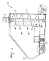
Figure 5 is a partially sectional side view of a further embodiment of a lawn mower according to the invention; -
Figure 6 is a view, similar toFigure 1 , of the embodiment of the lawn mower ofFigure 5 . - With reference to the cited figures, the lawn mower according to the invention, generally designated by the
reference numeral 101, comprises amowing plate 2 which accommodates a cutting means constituted, in the specific case, by three rotating blades 3a, 3b and 3c, that lie on the same imaginary plane and are arranged so that their rotation axes are positioned respectively at the corners of an imaginary triangle. - The blade 3b is thus extended toward the front part 30 of the
mowing plate 2, while the two blades 3a and 3c are in a retracted position and lie proximate to the rear part 40 of themowing plate 2. - In order to accumulate the mowed grass, above the
mowing plate 2 there is acontainer 4, the bottom of which is at least partially formed by the mowing plate itself and is connected thereto by means of aconveyance duct 5 which is formed substantially at the blade 3b but proximate to the rear part 40 of themowing plate 2. - According to the invention, there is a motion and compression means 6 adapted to convey the mowed grass into the
container 4 and to compress it thereat so as to utilize the available volume in an optimum manner. - In the specific case, the motion and compression means 6 is constituted by a rotating
screw feeder 7 which is inserted partially in theconveyance duct 5 and in which the rotation axis is substantially perpendicular to the imaginary plane defined by the rotating blades 3a, 3b and 3c. - The rotating
screw feeder 7 is turned by an actuation means which is constituted by ahydraulic motor 8 coupled to thepivot 9 of the rotatingscrew feeder 7, by means of an elastic coupling, not shown in the figures. - In order to allow the discharge of the mowed grass accumulated in the
container 4, an automatically-openingdoor 10 is activated when acontrol 11 is operated. Multiple venting openings, not shown in the accompanying figures, are provided on the walls for the outflow of the air introduced in thecontainer 4 after the cutting operations. - The lawn mower can be applied to tractors or telescopic motion units by means of quick-
coupling devices 12, connected to a deformable supportingchassis 13 which is articulated to themowing plate 2 so that the monolithic body constituted by themowing plate 2 and by thecontainer 4 can oscillate with respect to thepivoting axis 50, remaining in any case in stable equilibrium. - The correct and constant height from the ground of the cutting means is ensured by the presence of four supporting rollers, of which only the
rollers 14a and 14b are clearly visible in the accompanying figures, their rotation axis being movable toward or away from the imaginary plane formed by the rotating blades blades 3a, 3b and 3c. -
Figures 5 and6 illustrate a lawn mower, according to a further aspect of the invention, generally designated by thereference numeral 201, wherein for the outflow of the air introduced in thecontainer 4 during the cutting operations, there is arecycling duct 215 formed proximate to the rear part 40 of themowing plate 2, and substantially at the blade 3a, so as to return the air into themowing plate 2, producing a continuous recirculation between thecontainer 4 and the mowing plate. - In the embodiment shown in
Figures 5 and6 , the parts that correspond to the parts that have already been described with reference to the embodiment shown inFigures 1 to 4 , have been designated by the same reference numerals. - The operation of the lawn mower according to the invention is as follows.
- The lawn mower, coupled to a tractor or to the arm of a motion unit, is rested on the ground so that the four supporting rollers can ensure a certain uniformity in the cutting height, which is set by the operator after appropriately adjusting the distance of the rotation axes from the imaginary plane formed by the rotating blades 3 a, 3b, 3c.
- Because of the arrangement of the blades and of their rotation in the same direction, a circulating stream of air is generated inside the
mowing plate 2 and starts from the blade 3a, reaches the blade 3b, and finally the blade 3c, as shown inFigure 2 . - This air stream, together with the mechanical propelling action of the blades, conveys the mowed grass proximate to the
conveyance duct 5, where the rotatingscrew feeder 7, driven by thehydraulic motor 8, mechanically lifts the mowed grass and distributes and compresses it within thecontainer 4. - In the first of the two embodiments, the air introduced in the
container 4 is vented successively through venting openings, while in the embodiment shown inFigures 5 and6 the air returns through therecirculation duct 215 to themowing plate 2, substantially at the blade 3a, which starts the circulating flow, stream, thus creating a continuous recirculation. - The grass accumulated and pressed within the
container 4 can be conveniently evacuated by lifting the lawn mower and varying the inclination of the imaginary plane formed by the rotating blades 3a, 3b and 3c with respect to the ground, thus causing the opening of the automatically-openingdoor 10 and the consequent fall of the various cutting residues. - In practice it has been found that the lawn mower according to the invention fully achieves the intended aim, being capable of working effectively even in case of tall or wet grass and ensures the possibility to utilize in the best possible way the space available within the collector.
- The lawn mower thus conceived is susceptible of numerous modifications and variations, within the scope of the claims.
- All the details may be replaced with other technically equivalent elements.
- In practice, the materials used, so long as they are compatible with the specific use, as well as the contingent shapes and dimensions, may be any according to the requirements and the state of the art.
Claims (6)
- A lawn mower comprising a mowing plate (2) provided with a cutting means (3a, 3b, 3c), at least one container (4) for accumulating the mowed grass, said mowing plate (2) being connected to said container (4) by means of at least one conveyance duct (5), a motion and compression means (6) adapted to convey and compress said mowed grass inside said container, said motion and compression means comprising at least one rotating screw feeder (7) at least partially arranged within said conveyance duct (5), said rotating screw feeder (7) being turned by an actuation means (8), said cutting means comprising three rotating blades (3a, 3b, 3c) that are coplanar and have respective rotation axes that are arranged substantially at the corners of an imaginary triangle; said lawn mower being characterized in that said conveyance duct (5) is arranged within said container, said rotating screw feeder (7) having a rotation axis which is substantially perpendicular to an imaginary plane formed by said cutting means (3a, 3b, 3c), said screw feeder (7) extending from said mowing plate (2) directly into said container (4) substantially up to the top of said container (4).
- The lawn mower according to claim 1, characterized in that said actuation means comprises at least one hydraulic motor (8) coupled to said screw feeder (7).
- The lawn mower according to claim 1, characterized in that said container (4) comprises at least one automatically-opening door (10) in order to allow the discharge of said mowed grass.
- The lawn mower according to claim 1, characterized in that it comprises a deformable supporting chassis (13) articulated to said mowing plate (2).
- The lawn mower according to claim 4, characterized in that said deformable supporting chassis (13) comprises quick-coupling devices (12).
- The lawn mower according to claim 1, characterized in that it comprises at least one recirculation duct (215) adapted to generate a stream of air which is directed from said container (4) towards said mowing plate (2).
Priority Applications (2)
| Application Number | Priority Date | Filing Date | Title |
|---|---|---|---|
| PL05024470T PL1656825T3 (en) | 2004-11-10 | 2005-11-09 | Lawn mower |
| SI200532214T SI1656825T1 (en) | 2004-11-10 | 2005-11-09 | Lawn mower |
Applications Claiming Priority (1)
| Application Number | Priority Date | Filing Date | Title |
|---|---|---|---|
| ITVI20040259 ITVI20040259A1 (en) | 2004-11-10 | 2004-11-10 | MOWING DEVICE |
Publications (2)
| Publication Number | Publication Date |
|---|---|
| EP1656825A1 EP1656825A1 (en) | 2006-05-17 |
| EP1656825B1 true EP1656825B1 (en) | 2018-04-18 |
Family
ID=35677543
Family Applications (1)
| Application Number | Title | Priority Date | Filing Date |
|---|---|---|---|
| EP05024470.6A Expired - Lifetime EP1656825B1 (en) | 2004-11-10 | 2005-11-09 | Lawn mower |
Country Status (6)
| Country | Link |
|---|---|
| EP (1) | EP1656825B1 (en) |
| DK (1) | DK1656825T3 (en) |
| ES (1) | ES2677019T3 (en) |
| IT (1) | ITVI20040259A1 (en) |
| PL (1) | PL1656825T3 (en) |
| SI (1) | SI1656825T1 (en) |
Families Citing this family (2)
| Publication number | Priority date | Publication date | Assignee | Title |
|---|---|---|---|---|
| CN103283401A (en) * | 2013-06-28 | 2013-09-11 | 苏州金威特工具有限公司 | Mowing machine with propelling threaded rod |
| CN116602119B (en) * | 2023-06-25 | 2025-07-22 | 南京腾亚机器人科技有限公司 | Automatic intelligent lawn mower of packing of collection grass |
Family Cites Families (9)
| Publication number | Priority date | Publication date | Assignee | Title |
|---|---|---|---|---|
| US3736736A (en) * | 1972-03-06 | 1973-06-05 | Deere & Co | Baling attachment for lawn mowers |
| US4069649A (en) * | 1976-04-15 | 1978-01-24 | Excel Industries, Inc. | Grass and leaf collector and compactor attachment for mowers |
| DE4336821A1 (en) * | 1993-10-28 | 1995-05-04 | Eggenmueller Alfred | Lawn tractor with front-mounted mowing unit and sweeping machine |
| DE9405833U1 (en) * | 1994-04-11 | 1994-07-21 | Maschinen-Mohr, Inh. Hermann Mohr, 91792 Ellingen | Collection device for grass, leaves, dirt with integrated blower and high emptying |
| GB9505345D0 (en) * | 1995-03-16 | 1995-05-03 | Bozeat Miles R W | Improved grass cutting and collection machine |
| EP0759268A1 (en) * | 1995-08-11 | 1997-02-26 | Alfred Dr. Eggenmüller | Method and device for collecting and compacting plant matter |
| FR2773046A1 (en) * | 1997-01-15 | 1999-07-02 | Amazone Machines Agricoles Sa | Archimedian screw conveyor for mower, |
| DE29800014U1 (en) * | 1998-01-02 | 1998-03-05 | SULO Eisenwerk Streuber & Lohmann GmbH, 32051 Herford | mowing machine |
| JP3527191B2 (en) * | 2000-09-29 | 2004-05-17 | 株式会社クボタ | Riding mower |
-
2004
- 2004-11-10 IT ITVI20040259 patent/ITVI20040259A1/en unknown
-
2005
- 2005-11-09 ES ES05024470.6T patent/ES2677019T3/en not_active Expired - Lifetime
- 2005-11-09 DK DK05024470.6T patent/DK1656825T3/en active
- 2005-11-09 PL PL05024470T patent/PL1656825T3/en unknown
- 2005-11-09 EP EP05024470.6A patent/EP1656825B1/en not_active Expired - Lifetime
- 2005-11-09 SI SI200532214T patent/SI1656825T1/en unknown
Non-Patent Citations (1)
| Title |
|---|
| None * |
Also Published As
| Publication number | Publication date |
|---|---|
| SI1656825T1 (en) | 2018-09-28 |
| DK1656825T3 (en) | 2018-07-23 |
| PL1656825T3 (en) | 2018-10-31 |
| ITVI20040259A1 (en) | 2005-02-10 |
| EP1656825A1 (en) | 2006-05-17 |
| ES2677019T3 (en) | 2018-07-27 |
Similar Documents
| Publication | Publication Date | Title |
|---|---|---|
| US4597203A (en) | Convertible snowblower using rectangular shroud interface | |
| US5020309A (en) | Leaf shredder attachment for a mower bagging system | |
| CN104480884B (en) | All-in-one is pulverized in a kind of fallen leaves cleaning | |
| US20080250768A1 (en) | Mulch plate apparatus with adjustable handle mechanism | |
| US3588179A (en) | Power mower clipping-collecting attachment-collecting trailer therefor | |
| US4741148A (en) | Tractor attached leaf or clipping blower/vacuum device | |
| US6675566B2 (en) | Tool, such as a lawnmower or the like, particularly for gardening vehicles | |
| US3367092A (en) | Power mower attachment | |
| EP1656825A1 (en) | Lawn mower | |
| US6658830B2 (en) | Self-propelled flail mower and vacuum | |
| CN109258076B (en) | Multifunctional mower | |
| CN209066357U (en) | A garden leaf suction machine with crushing function | |
| US5517811A (en) | Pivoting grass chute | |
| CN221748970U (en) | A lawn mowing device for property greening management | |
| CN209914530U (en) | A trimmer for trimming rectangular green belts | |
| CN107258212B (en) | Automatic lawn trimmer | |
| KR20130127133A (en) | Hay rake mounted having front of working vehicle | |
| CN113141854B (en) | Device for trimming lawn for greening | |
| US20210185943A1 (en) | Lawn Debris Hopper, and Associated Devices, Systems and Methods | |
| EP0821867B1 (en) | Lawnmower with grass collector | |
| CN115474473B (en) | A lawn trimmer that improves the trimming effect and leaves no residue | |
| CN223943263U (en) | Grass collecting device and grass cutting equipment | |
| CN218680102U (en) | Weeder convenient to collect garrulous grass | |
| CN219410687U (en) | Fallen leaf suction pick-up, cutting, collecting and bagging machine | |
| US5357736A (en) | Lawn mower with means for selectively collecting grass and grass plus garden debris, and method of using |
Legal Events
| Date | Code | Title | Description |
|---|---|---|---|
| PUAI | Public reference made under article 153(3) epc to a published international application that has entered the european phase |
Free format text: ORIGINAL CODE: 0009012 |
|
| AK | Designated contracting states |
Kind code of ref document: A1 Designated state(s): AT BE BG CH CY CZ DE DK EE ES FI FR GB GR HU IE IS IT LI LT LU LV MC NL PL PT RO SE SI SK TR |
|
| AX | Request for extension of the european patent |
Extension state: AL BA HR MK YU |
|
| 17P | Request for examination filed |
Effective date: 20061026 |
|
| 17Q | First examination report despatched |
Effective date: 20061207 |
|
| AKX | Designation fees paid |
Designated state(s): AT BE BG CH CY CZ DE DK EE ES FI FR GB GR HU IE IS IT LI LT LU LV MC NL PL PT RO SE SI SK TR |
|
| RAP1 | Party data changed (applicant data changed or rights of an application transferred) |
Owner name: MULTIONE SRL |
|
| GRAP | Despatch of communication of intention to grant a patent |
Free format text: ORIGINAL CODE: EPIDOSNIGR1 |
|
| INTG | Intention to grant announced |
Effective date: 20171109 |
|
| GRAS | Grant fee paid |
Free format text: ORIGINAL CODE: EPIDOSNIGR3 |
|
| GRAA | (expected) grant |
Free format text: ORIGINAL CODE: 0009210 |
|
| AK | Designated contracting states |
Kind code of ref document: B1 Designated state(s): AT BE BG CH CY CZ DE DK EE ES FI FR GB GR HU IE IS IT LI LT LU LV MC NL PL PT RO SE SI SK TR |
|
| REG | Reference to a national code |
Ref country code: GB Ref legal event code: FG4D |
|
| REG | Reference to a national code |
Ref country code: CH Ref legal event code: EP |
|
| REG | Reference to a national code |
Ref country code: DE Ref legal event code: R096 Ref document number: 602005053835 Country of ref document: DE |
|
| REG | Reference to a national code |
Ref country code: AT Ref legal event code: REF Ref document number: 989378 Country of ref document: AT Kind code of ref document: T Effective date: 20180515 |
|
| REG | Reference to a national code |
Ref country code: IE Ref legal event code: FG4D |
|
| REG | Reference to a national code |
Ref country code: RO Ref legal event code: EPE |
|
| REG | Reference to a national code |
Ref country code: DK Ref legal event code: T3 Effective date: 20180717 |
|
| REG | Reference to a national code |
Ref country code: ES Ref legal event code: FG2A Ref document number: 2677019 Country of ref document: ES Kind code of ref document: T3 Effective date: 20180727 |
|
| REG | Reference to a national code |
Ref country code: SE Ref legal event code: TRGR |
|
| REG | Reference to a national code |
Ref country code: NL Ref legal event code: FP |
|
| REG | Reference to a national code |
Ref country code: LT Ref legal event code: MG4D |
|
| REG | Reference to a national code |
Ref country code: EE Ref legal event code: FG4A Ref document number: 015735 Country of ref document: EE Effective date: 20180710 |
|
| REG | Reference to a national code |
Ref country code: FR Ref legal event code: PLFP Year of fee payment: 14 |
|
| PG25 | Lapsed in a contracting state [announced via postgrant information from national office to epo] |
Ref country code: LT Free format text: LAPSE BECAUSE OF FAILURE TO SUBMIT A TRANSLATION OF THE DESCRIPTION OR TO PAY THE FEE WITHIN THE PRESCRIBED TIME-LIMIT Effective date: 20180418 |
|
| REG | Reference to a national code |
Ref country code: SK Ref legal event code: T3 Ref document number: E 27994 Country of ref document: SK |
|
| PG25 | Lapsed in a contracting state [announced via postgrant information from national office to epo] |
Ref country code: LV Free format text: LAPSE BECAUSE OF FAILURE TO SUBMIT A TRANSLATION OF THE DESCRIPTION OR TO PAY THE FEE WITHIN THE PRESCRIBED TIME-LIMIT Effective date: 20180418 Ref country code: GR Free format text: LAPSE BECAUSE OF FAILURE TO SUBMIT A TRANSLATION OF THE DESCRIPTION OR TO PAY THE FEE WITHIN THE PRESCRIBED TIME-LIMIT Effective date: 20180719 |
|
| PG25 | Lapsed in a contracting state [announced via postgrant information from national office to epo] |
Ref country code: PT Free format text: LAPSE BECAUSE OF FAILURE TO SUBMIT A TRANSLATION OF THE DESCRIPTION OR TO PAY THE FEE WITHIN THE PRESCRIBED TIME-LIMIT Effective date: 20180820 |
|
| REG | Reference to a national code |
Ref country code: DE Ref legal event code: R097 Ref document number: 602005053835 Country of ref document: DE |
|
| PLBE | No opposition filed within time limit |
Free format text: ORIGINAL CODE: 0009261 |
|
| STAA | Information on the status of an ep patent application or granted ep patent |
Free format text: STATUS: NO OPPOSITION FILED WITHIN TIME LIMIT |
|
| 26N | No opposition filed |
Effective date: 20190121 |
|
| PG25 | Lapsed in a contracting state [announced via postgrant information from national office to epo] |
Ref country code: MC Free format text: LAPSE BECAUSE OF FAILURE TO SUBMIT A TRANSLATION OF THE DESCRIPTION OR TO PAY THE FEE WITHIN THE PRESCRIBED TIME-LIMIT Effective date: 20180418 Ref country code: LU Free format text: LAPSE BECAUSE OF NON-PAYMENT OF DUE FEES Effective date: 20181109 |
|
| PGFP | Annual fee paid to national office [announced via postgrant information from national office to epo] |
Ref country code: IE Payment date: 20191023 Year of fee payment: 15 Ref country code: BG Payment date: 20191030 Year of fee payment: 15 Ref country code: RO Payment date: 20191105 Year of fee payment: 15 |
|
| PGFP | Annual fee paid to national office [announced via postgrant information from national office to epo] |
Ref country code: SI Payment date: 20191024 Year of fee payment: 15 |
|
| PG25 | Lapsed in a contracting state [announced via postgrant information from national office to epo] |
Ref country code: TR Free format text: LAPSE BECAUSE OF FAILURE TO SUBMIT A TRANSLATION OF THE DESCRIPTION OR TO PAY THE FEE WITHIN THE PRESCRIBED TIME-LIMIT Effective date: 20180418 |
|
| PG25 | Lapsed in a contracting state [announced via postgrant information from national office to epo] |
Ref country code: CY Free format text: LAPSE BECAUSE OF FAILURE TO SUBMIT A TRANSLATION OF THE DESCRIPTION OR TO PAY THE FEE WITHIN THE PRESCRIBED TIME-LIMIT Effective date: 20180418 Ref country code: HU Free format text: LAPSE BECAUSE OF FAILURE TO SUBMIT A TRANSLATION OF THE DESCRIPTION OR TO PAY THE FEE WITHIN THE PRESCRIBED TIME-LIMIT; INVALID AB INITIO Effective date: 20051109 |
|
| PG25 | Lapsed in a contracting state [announced via postgrant information from national office to epo] |
Ref country code: IS Free format text: LAPSE BECAUSE OF FAILURE TO SUBMIT A TRANSLATION OF THE DESCRIPTION OR TO PAY THE FEE WITHIN THE PRESCRIBED TIME-LIMIT Effective date: 20180818 |
|
| PGFP | Annual fee paid to national office [announced via postgrant information from national office to epo] |
Ref country code: SK Payment date: 20200828 Year of fee payment: 16 |
|
| PGFP | Annual fee paid to national office [announced via postgrant information from national office to epo] |
Ref country code: CZ Payment date: 20201008 Year of fee payment: 16 Ref country code: AT Payment date: 20201007 Year of fee payment: 16 |
|
| REG | Reference to a national code |
Ref country code: AT Ref legal event code: UEP Ref document number: 989378 Country of ref document: AT Kind code of ref document: T Effective date: 20180418 |
|
| PG25 | Lapsed in a contracting state [announced via postgrant information from national office to epo] |
Ref country code: BG Free format text: LAPSE BECAUSE OF NON-PAYMENT OF DUE FEES Effective date: 20210531 Ref country code: RO Free format text: LAPSE BECAUSE OF NON-PAYMENT OF DUE FEES Effective date: 20201109 |
|
| PG25 | Lapsed in a contracting state [announced via postgrant information from national office to epo] |
Ref country code: SI Free format text: LAPSE BECAUSE OF NON-PAYMENT OF DUE FEES Effective date: 20201110 |
|
| REG | Reference to a national code |
Ref country code: SI Ref legal event code: KO00 Effective date: 20210811 |
|
| PG25 | Lapsed in a contracting state [announced via postgrant information from national office to epo] |
Ref country code: IE Free format text: LAPSE BECAUSE OF NON-PAYMENT OF DUE FEES Effective date: 20201109 |
|
| PGFP | Annual fee paid to national office [announced via postgrant information from national office to epo] |
Ref country code: ES Payment date: 20211201 Year of fee payment: 17 Ref country code: GB Payment date: 20211124 Year of fee payment: 17 |
|
| PGFP | Annual fee paid to national office [announced via postgrant information from national office to epo] |
Ref country code: CH Payment date: 20211007 Year of fee payment: 17 |
|
| REG | Reference to a national code |
Ref country code: SK Ref legal event code: MM4A Ref document number: E 27994 Country of ref document: SK Effective date: 20211109 |
|
| REG | Reference to a national code |
Ref country code: AT Ref legal event code: MM01 Ref document number: 989378 Country of ref document: AT Kind code of ref document: T Effective date: 20211109 |
|
| PG25 | Lapsed in a contracting state [announced via postgrant information from national office to epo] |
Ref country code: SK Free format text: LAPSE BECAUSE OF NON-PAYMENT OF DUE FEES Effective date: 20211109 Ref country code: CZ Free format text: LAPSE BECAUSE OF NON-PAYMENT OF DUE FEES Effective date: 20211109 |
|
| PG25 | Lapsed in a contracting state [announced via postgrant information from national office to epo] |
Ref country code: AT Free format text: LAPSE BECAUSE OF NON-PAYMENT OF DUE FEES Effective date: 20211109 |
|
| REG | Reference to a national code |
Ref country code: CH Ref legal event code: PL |
|
| P01 | Opt-out of the competence of the unified patent court (upc) registered |
Effective date: 20230529 |
|
| GBPC | Gb: european patent ceased through non-payment of renewal fee |
Effective date: 20221109 |
|
| PG25 | Lapsed in a contracting state [announced via postgrant information from national office to epo] |
Ref country code: LI Free format text: LAPSE BECAUSE OF NON-PAYMENT OF DUE FEES Effective date: 20221130 Ref country code: CH Free format text: LAPSE BECAUSE OF NON-PAYMENT OF DUE FEES Effective date: 20221130 |
|
| PG25 | Lapsed in a contracting state [announced via postgrant information from national office to epo] |
Ref country code: GB Free format text: LAPSE BECAUSE OF NON-PAYMENT OF DUE FEES Effective date: 20221109 |
|
| REG | Reference to a national code |
Ref country code: ES Ref legal event code: FD2A Effective date: 20231228 |
|
| PG25 | Lapsed in a contracting state [announced via postgrant information from national office to epo] |
Ref country code: ES Free format text: LAPSE BECAUSE OF NON-PAYMENT OF DUE FEES Effective date: 20221110 |
|
| PG25 | Lapsed in a contracting state [announced via postgrant information from national office to epo] |
Ref country code: ES Free format text: LAPSE BECAUSE OF NON-PAYMENT OF DUE FEES Effective date: 20221110 |
|
| PGFP | Annual fee paid to national office [announced via postgrant information from national office to epo] |
Ref country code: IT Payment date: 20240925 Year of fee payment: 20 |
|
| PGFP | Annual fee paid to national office [announced via postgrant information from national office to epo] |
Ref country code: NL Payment date: 20241119 Year of fee payment: 20 |
|
| PGFP | Annual fee paid to national office [announced via postgrant information from national office to epo] |
Ref country code: DE Payment date: 20241213 Year of fee payment: 20 |
|
| PGFP | Annual fee paid to national office [announced via postgrant information from national office to epo] |
Ref country code: DK Payment date: 20241118 Year of fee payment: 20 |
|
| PGFP | Annual fee paid to national office [announced via postgrant information from national office to epo] |
Ref country code: BE Payment date: 20241113 Year of fee payment: 20 Ref country code: FI Payment date: 20241111 Year of fee payment: 20 Ref country code: PL Payment date: 20241106 Year of fee payment: 20 |
|
| PGFP | Annual fee paid to national office [announced via postgrant information from national office to epo] |
Ref country code: FR Payment date: 20241127 Year of fee payment: 20 |
|
| PGFP | Annual fee paid to national office [announced via postgrant information from national office to epo] |
Ref country code: EE Payment date: 20241111 Year of fee payment: 20 |
|
| PGFP | Annual fee paid to national office [announced via postgrant information from national office to epo] |
Ref country code: SE Payment date: 20241030 Year of fee payment: 20 |
|
| REG | Reference to a national code |
Ref country code: DE Ref legal event code: R071 Ref document number: 602005053835 Country of ref document: DE |
|
| REG | Reference to a national code |
Ref country code: DK Ref legal event code: EUP Expiry date: 20251109 |
|
| REG | Reference to a national code |
Ref country code: NL Ref legal event code: MK Effective date: 20251108 |
|
| REG | Reference to a national code |
Ref country code: BE Ref legal event code: MK Effective date: 20251109 |