EP1656166B1 - Tissue repair and replacement - Google Patents
Tissue repair and replacement Download PDFInfo
- Publication number
- EP1656166B1 EP1656166B1 EP04781909A EP04781909A EP1656166B1 EP 1656166 B1 EP1656166 B1 EP 1656166B1 EP 04781909 A EP04781909 A EP 04781909A EP 04781909 A EP04781909 A EP 04781909A EP 1656166 B1 EP1656166 B1 EP 1656166B1
- Authority
- EP
- European Patent Office
- Prior art keywords
- component
- ceramic
- scaffold
- porous
- polymer
- Prior art date
- Legal status (The legal status is an assumption and is not a legal conclusion. Google has not performed a legal analysis and makes no representation as to the accuracy of the status listed.)
- Expired - Lifetime
Links
- 230000017423 tissue regeneration Effects 0.000 title claims description 5
- 230000015556 catabolic process Effects 0.000 claims abstract description 29
- 238000006731 degradation reaction Methods 0.000 claims abstract description 27
- 238000001727 in vivo Methods 0.000 claims abstract description 22
- 239000000919 ceramic Substances 0.000 claims description 67
- 239000011148 porous material Substances 0.000 claims description 22
- 238000000034 method Methods 0.000 claims description 16
- 239000000654 additive Substances 0.000 claims description 10
- 238000002513 implantation Methods 0.000 claims description 9
- 238000001746 injection moulding Methods 0.000 claims description 5
- 230000000996 additive effect Effects 0.000 claims description 4
- 239000007788 liquid Substances 0.000 claims description 4
- 230000001225 therapeutic effect Effects 0.000 claims description 4
- 238000004519 manufacturing process Methods 0.000 claims description 2
- 210000001519 tissue Anatomy 0.000 abstract description 31
- 210000000988 bone and bone Anatomy 0.000 abstract description 27
- 229920000642 polymer Polymers 0.000 description 79
- 239000012071 phase Substances 0.000 description 32
- 239000000203 mixture Substances 0.000 description 19
- -1 e.g. Substances 0.000 description 17
- 239000000178 monomer Substances 0.000 description 13
- 239000002131 composite material Substances 0.000 description 12
- 239000001506 calcium phosphate Substances 0.000 description 10
- 230000000593 degrading effect Effects 0.000 description 10
- 239000000463 material Substances 0.000 description 10
- QORWJWZARLRLPR-UHFFFAOYSA-H tricalcium bis(phosphate) Chemical class [Ca+2].[Ca+2].[Ca+2].[O-]P([O-])([O-])=O.[O-]P([O-])([O-])=O QORWJWZARLRLPR-UHFFFAOYSA-H 0.000 description 10
- OSGAYBCDTDRGGQ-UHFFFAOYSA-L calcium sulfate Chemical compound [Ca+2].[O-]S([O-])(=O)=O OSGAYBCDTDRGGQ-UHFFFAOYSA-L 0.000 description 9
- 229920001432 poly(L-lactide) Polymers 0.000 description 9
- JVTAAEKCZFNVCJ-REOHCLBHSA-N L-lactic acid Chemical compound C[C@H](O)C(O)=O JVTAAEKCZFNVCJ-REOHCLBHSA-N 0.000 description 8
- 229910000391 tricalcium phosphate Inorganic materials 0.000 description 8
- 235000019731 tricalcium phosphate Nutrition 0.000 description 8
- 229940078499 tricalcium phosphate Drugs 0.000 description 8
- 229920000954 Polyglycolide Polymers 0.000 description 7
- 229910052588 hydroxylapatite Inorganic materials 0.000 description 7
- 230000008595 infiltration Effects 0.000 description 7
- 238000001764 infiltration Methods 0.000 description 7
- XYJRXVWERLGGKC-UHFFFAOYSA-D pentacalcium;hydroxide;triphosphate Chemical compound [OH-].[Ca+2].[Ca+2].[Ca+2].[Ca+2].[Ca+2].[O-]P([O-])([O-])=O.[O-]P([O-])([O-])=O.[O-]P([O-])([O-])=O XYJRXVWERLGGKC-UHFFFAOYSA-D 0.000 description 7
- IJGRMHOSHXDMSA-UHFFFAOYSA-N Atomic nitrogen Chemical compound N#N IJGRMHOSHXDMSA-UHFFFAOYSA-N 0.000 description 6
- 230000007547 defect Effects 0.000 description 6
- 238000005191 phase separation Methods 0.000 description 6
- 229920000747 poly(lactic acid) Polymers 0.000 description 6
- 239000004633 polyglycolic acid Substances 0.000 description 6
- 230000008439 repair process Effects 0.000 description 6
- 238000006243 chemical reaction Methods 0.000 description 5
- 239000008367 deionised water Substances 0.000 description 5
- 239000007943 implant Substances 0.000 description 5
- 229920001610 polycaprolactone Polymers 0.000 description 5
- 239000004632 polycaprolactone Substances 0.000 description 5
- XLYOFNOQVPJJNP-UHFFFAOYSA-N water Substances O XLYOFNOQVPJJNP-UHFFFAOYSA-N 0.000 description 5
- RTZKZFJDLAIYFH-UHFFFAOYSA-N Diethyl ether Chemical compound CCOCC RTZKZFJDLAIYFH-UHFFFAOYSA-N 0.000 description 4
- 229920002732 Polyanhydride Polymers 0.000 description 4
- 229910010293 ceramic material Inorganic materials 0.000 description 4
- 230000000694 effects Effects 0.000 description 4
- 239000000839 emulsion Substances 0.000 description 4
- 229920002959 polymer blend Polymers 0.000 description 4
- 238000002360 preparation method Methods 0.000 description 4
- 239000000243 solution Substances 0.000 description 4
- LYCAIKOWRPUZTN-UHFFFAOYSA-N Ethylene glycol Chemical compound OCCO LYCAIKOWRPUZTN-UHFFFAOYSA-N 0.000 description 3
- 210000004027 cell Anatomy 0.000 description 3
- 150000001875 compounds Chemical class 0.000 description 3
- 229910021641 deionized water Inorganic materials 0.000 description 3
- 239000011521 glass Substances 0.000 description 3
- 239000008187 granular material Substances 0.000 description 3
- 238000011065 in-situ storage Methods 0.000 description 3
- JVTAAEKCZFNVCJ-UHFFFAOYSA-N lactic acid Chemical compound CC(O)C(O)=O JVTAAEKCZFNVCJ-UHFFFAOYSA-N 0.000 description 3
- 239000011159 matrix material Substances 0.000 description 3
- 239000000155 melt Substances 0.000 description 3
- 238000002844 melting Methods 0.000 description 3
- 230000008018 melting Effects 0.000 description 3
- 238000000465 moulding Methods 0.000 description 3
- 229910052757 nitrogen Inorganic materials 0.000 description 3
- 239000000126 substance Substances 0.000 description 3
- 238000012360 testing method Methods 0.000 description 3
- KWGRBVOPPLSCSI-WPRPVWTQSA-N (-)-ephedrine Chemical compound CN[C@@H](C)[C@H](O)C1=CC=CC=C1 KWGRBVOPPLSCSI-WPRPVWTQSA-N 0.000 description 2
- KAKZBPTYRLMSJV-UHFFFAOYSA-N Butadiene Chemical group C=CC=C KAKZBPTYRLMSJV-UHFFFAOYSA-N 0.000 description 2
- VTYYLEPIZMXCLO-UHFFFAOYSA-L Calcium carbonate Chemical compound [Ca+2].[O-]C([O-])=O VTYYLEPIZMXCLO-UHFFFAOYSA-L 0.000 description 2
- YMWUJEATGCHHMB-UHFFFAOYSA-N Dichloromethane Chemical compound ClCCl YMWUJEATGCHHMB-UHFFFAOYSA-N 0.000 description 2
- 102000018233 Fibroblast Growth Factor Human genes 0.000 description 2
- 108050007372 Fibroblast Growth Factor Proteins 0.000 description 2
- 108090000723 Insulin-Like Growth Factor I Proteins 0.000 description 2
- PVNIIMVLHYAWGP-UHFFFAOYSA-N Niacin Chemical compound OC(=O)C1=CC=CN=C1 PVNIIMVLHYAWGP-UHFFFAOYSA-N 0.000 description 2
- 241001494479 Pecora Species 0.000 description 2
- 102000010780 Platelet-Derived Growth Factor Human genes 0.000 description 2
- 108010038512 Platelet-Derived Growth Factor Proteins 0.000 description 2
- 229920001710 Polyorthoester Polymers 0.000 description 2
- 238000010521 absorption reaction Methods 0.000 description 2
- 229920002988 biodegradable polymer Polymers 0.000 description 2
- 239000004621 biodegradable polymer Substances 0.000 description 2
- 230000015572 biosynthetic process Effects 0.000 description 2
- 230000008468 bone growth Effects 0.000 description 2
- 235000011010 calcium phosphates Nutrition 0.000 description 2
- 239000000969 carrier Substances 0.000 description 2
- 239000003054 catalyst Substances 0.000 description 2
- 230000001413 cellular effect Effects 0.000 description 2
- 239000003795 chemical substances by application Substances 0.000 description 2
- 238000001816 cooling Methods 0.000 description 2
- 229920001577 copolymer Polymers 0.000 description 2
- 239000002173 cutting fluid Substances 0.000 description 2
- 229910003460 diamond Inorganic materials 0.000 description 2
- 239000010432 diamond Substances 0.000 description 2
- RBLGLDWTCZMLRW-UHFFFAOYSA-K dicalcium;phosphate;dihydrate Chemical compound O.O.[Ca+2].[Ca+2].[O-]P([O-])([O-])=O RBLGLDWTCZMLRW-UHFFFAOYSA-K 0.000 description 2
- POULHZVOKOAJMA-UHFFFAOYSA-N dodecanoic acid Chemical compound CCCCCCCCCCCC(O)=O POULHZVOKOAJMA-UHFFFAOYSA-N 0.000 description 2
- 230000003628 erosive effect Effects 0.000 description 2
- 229940126864 fibroblast growth factor Drugs 0.000 description 2
- 230000035876 healing Effects 0.000 description 2
- 229920005621 immiscible polymer blend Polymers 0.000 description 2
- 239000003999 initiator Substances 0.000 description 2
- 230000000977 initiatory effect Effects 0.000 description 2
- 229960000448 lactic acid Drugs 0.000 description 2
- 239000012528 membrane Substances 0.000 description 2
- 239000012299 nitrogen atmosphere Substances 0.000 description 2
- 239000002245 particle Substances 0.000 description 2
- VCMMXZQDRFWYSE-UHFFFAOYSA-N plumbagin Chemical compound C1=CC=C2C(=O)C(C)=CC(=O)C2=C1O VCMMXZQDRFWYSE-UHFFFAOYSA-N 0.000 description 2
- 229920000117 poly(dioxanone) Polymers 0.000 description 2
- 229920000515 polycarbonate Polymers 0.000 description 2
- 239000004417 polycarbonate Substances 0.000 description 2
- 229920006324 polyoxymethylene Polymers 0.000 description 2
- 229920002635 polyurethane Polymers 0.000 description 2
- 239000004814 polyurethane Substances 0.000 description 2
- 108090000765 processed proteins & peptides Proteins 0.000 description 2
- 239000000047 product Substances 0.000 description 2
- LOUPRKONTZGTKE-LHHVKLHASA-N quinidine Chemical compound C([C@H]([C@H](C1)C=C)C2)C[N@@]1[C@H]2[C@@H](O)C1=CC=NC2=CC=C(OC)C=C21 LOUPRKONTZGTKE-LHHVKLHASA-N 0.000 description 2
- 238000007634 remodeling Methods 0.000 description 2
- 210000004872 soft tissue Anatomy 0.000 description 2
- 239000013589 supplement Substances 0.000 description 2
- YFHICDDUDORKJB-UHFFFAOYSA-N trimethylene carbonate Chemical compound O=C1OCCCO1 YFHICDDUDORKJB-UHFFFAOYSA-N 0.000 description 2
- MFRCZYUUKMFJQJ-UHFFFAOYSA-N 1,4-dioxane-2,5-dione;1,3-dioxan-2-one Chemical compound O=C1OCCCO1.O=C1COC(=O)CO1 MFRCZYUUKMFJQJ-UHFFFAOYSA-N 0.000 description 1
- STQGQHZAVUOBTE-UHFFFAOYSA-N 7-Cyan-hept-2t-en-4,6-diinsaeure Natural products C1=2C(O)=C3C(=O)C=4C(OC)=CC=CC=4C(=O)C3=C(O)C=2CC(O)(C(C)=O)CC1OC1CC(N)C(O)C(C)O1 STQGQHZAVUOBTE-UHFFFAOYSA-N 0.000 description 1
- BSYNRYMUTXBXSQ-UHFFFAOYSA-N Aspirin Chemical compound CC(=O)OC1=CC=CC=C1C(O)=O BSYNRYMUTXBXSQ-UHFFFAOYSA-N 0.000 description 1
- 229930003347 Atropine Natural products 0.000 description 1
- 206010065687 Bone loss Diseases 0.000 description 1
- 102000008186 Collagen Human genes 0.000 description 1
- 108010035532 Collagen Proteins 0.000 description 1
- RGHNJXZEOKUKBD-SQOUGZDYSA-N D-gluconic acid Chemical compound OC[C@@H](O)[C@@H](O)[C@H](O)[C@@H](O)C(O)=O RGHNJXZEOKUKBD-SQOUGZDYSA-N 0.000 description 1
- WEAHRLBPCANXCN-UHFFFAOYSA-N Daunomycin Natural products CCC1(O)CC(OC2CC(N)C(O)C(C)O2)c3cc4C(=O)c5c(OC)cccc5C(=O)c4c(O)c3C1 WEAHRLBPCANXCN-UHFFFAOYSA-N 0.000 description 1
- LTMHDMANZUZIPE-AMTYYWEZSA-N Digoxin Natural products O([C@H]1[C@H](C)O[C@H](O[C@@H]2C[C@@H]3[C@@](C)([C@@H]4[C@H]([C@]5(O)[C@](C)([C@H](O)C4)[C@H](C4=CC(=O)OC4)CC5)CC3)CC2)C[C@@H]1O)[C@H]1O[C@H](C)[C@@H](O[C@H]2O[C@@H](C)[C@H](O)[C@@H](O)C2)[C@@H](O)C1 LTMHDMANZUZIPE-AMTYYWEZSA-N 0.000 description 1
- 229910000997 High-speed steel Inorganic materials 0.000 description 1
- RKUNBYITZUJHSG-UHFFFAOYSA-N Hyosciamin-hydrochlorid Natural products CN1C(C2)CCC1CC2OC(=O)C(CO)C1=CC=CC=C1 RKUNBYITZUJHSG-UHFFFAOYSA-N 0.000 description 1
- HEFNNWSXXWATRW-UHFFFAOYSA-N Ibuprofen Chemical compound CC(C)CC1=CC=C(C(C)C(O)=O)C=C1 HEFNNWSXXWATRW-UHFFFAOYSA-N 0.000 description 1
- 102000008394 Immunoglobulin Fragments Human genes 0.000 description 1
- 108010021625 Immunoglobulin Fragments Proteins 0.000 description 1
- 102000004218 Insulin-Like Growth Factor I Human genes 0.000 description 1
- ZMOIGGHUSNHCAB-UHFFFAOYSA-N Isoplumbagin Natural products C1=CC(O)=C2C(=O)C(C)=CC(=O)C2=C1 ZMOIGGHUSNHCAB-UHFFFAOYSA-N 0.000 description 1
- ONIBWKKTOPOVIA-BYPYZUCNSA-N L-Proline Chemical compound OC(=O)[C@@H]1CCCN1 ONIBWKKTOPOVIA-BYPYZUCNSA-N 0.000 description 1
- 239000005639 Lauric acid Substances 0.000 description 1
- 206010028980 Neoplasm Diseases 0.000 description 1
- 229930195708 Penicillin V Natural products 0.000 description 1
- ONIBWKKTOPOVIA-UHFFFAOYSA-N Proline Natural products OC(=O)C1CCCN1 ONIBWKKTOPOVIA-UHFFFAOYSA-N 0.000 description 1
- 102000013275 Somatomedins Human genes 0.000 description 1
- 102000004887 Transforming Growth Factor beta Human genes 0.000 description 1
- 108090001012 Transforming Growth Factor beta Proteins 0.000 description 1
- 208000027418 Wounds and injury Diseases 0.000 description 1
- 229960001138 acetylsalicylic acid Drugs 0.000 description 1
- MKUXAQIIEYXACX-UHFFFAOYSA-N aciclovir Chemical compound N1C(N)=NC(=O)C2=C1N(COCCO)C=N2 MKUXAQIIEYXACX-UHFFFAOYSA-N 0.000 description 1
- 229960004150 aciclovir Drugs 0.000 description 1
- 239000002253 acid Substances 0.000 description 1
- 239000013543 active substance Substances 0.000 description 1
- 230000002411 adverse Effects 0.000 description 1
- 239000012736 aqueous medium Substances 0.000 description 1
- RKUNBYITZUJHSG-SPUOUPEWSA-N atropine Chemical compound O([C@H]1C[C@H]2CC[C@@H](C1)N2C)C(=O)C(CO)C1=CC=CC=C1 RKUNBYITZUJHSG-SPUOUPEWSA-N 0.000 description 1
- 229960000396 atropine Drugs 0.000 description 1
- ALPCEXCHMFUSAN-UHFFFAOYSA-N beta-Dihydroplumbagin Natural products C1=CC=C2C(=O)C(C)CC(=O)C2=C1O ALPCEXCHMFUSAN-UHFFFAOYSA-N 0.000 description 1
- 239000005312 bioglass Substances 0.000 description 1
- 229920001400 block copolymer Polymers 0.000 description 1
- 210000001124 body fluid Anatomy 0.000 description 1
- 239000010839 body fluid Substances 0.000 description 1
- 210000002449 bone cell Anatomy 0.000 description 1
- 229910000019 calcium carbonate Inorganic materials 0.000 description 1
- JUNWLZAGQLJVLR-UHFFFAOYSA-J calcium diphosphate Chemical compound [Ca+2].[Ca+2].[O-]P([O-])(=O)OP([O-])([O-])=O JUNWLZAGQLJVLR-UHFFFAOYSA-J 0.000 description 1
- 239000004068 calcium phosphate ceramic Substances 0.000 description 1
- ZOMBKNNSYQHRCA-UHFFFAOYSA-J calcium sulfate hemihydrate Chemical compound O.[Ca+2].[Ca+2].[O-]S([O-])(=O)=O.[O-]S([O-])(=O)=O ZOMBKNNSYQHRCA-UHFFFAOYSA-J 0.000 description 1
- 210000000845 cartilage Anatomy 0.000 description 1
- 229960000603 cefalotin Drugs 0.000 description 1
- XIURVHNZVLADCM-IUODEOHRSA-N cefalotin Chemical compound N([C@H]1[C@@H]2N(C1=O)C(=C(CS2)COC(=O)C)C(O)=O)C(=O)CC1=CC=CS1 XIURVHNZVLADCM-IUODEOHRSA-N 0.000 description 1
- 229960002588 cefradine Drugs 0.000 description 1
- 239000004568 cement Substances 0.000 description 1
- RDLPVSKMFDYCOR-UEKVPHQBSA-N cephradine Chemical compound C1([C@@H](N)C(=O)N[C@H]2[C@@H]3N(C2=O)C(=C(CS3)C)C(O)=O)=CCC=CC1 RDLPVSKMFDYCOR-UEKVPHQBSA-N 0.000 description 1
- 230000008859 change Effects 0.000 description 1
- 239000003153 chemical reaction reagent Substances 0.000 description 1
- JCKYGMPEJWAADB-UHFFFAOYSA-N chlorambucil Chemical compound OC(=O)CCCC1=CC=C(N(CCCl)CCCl)C=C1 JCKYGMPEJWAADB-UHFFFAOYSA-N 0.000 description 1
- 229960004630 chlorambucil Drugs 0.000 description 1
- SURLGNKAQXKNSP-DBLYXWCISA-N chlorin Chemical compound C\1=C/2\N/C(=C\C3=N/C(=C\C=4NC(/C=C\5/C=CC/1=N/5)=CC=4)/C=C3)/CC\2 SURLGNKAQXKNSP-DBLYXWCISA-N 0.000 description 1
- LOUPRKONTZGTKE-UHFFFAOYSA-N cinchonine Natural products C1C(C(C2)C=C)CCN2C1C(O)C1=CC=NC2=CC=C(OC)C=C21 LOUPRKONTZGTKE-UHFFFAOYSA-N 0.000 description 1
- PMMYEEVYMWASQN-IMJSIDKUSA-N cis-4-Hydroxy-L-proline Chemical compound O[C@@H]1CN[C@H](C(O)=O)C1 PMMYEEVYMWASQN-IMJSIDKUSA-N 0.000 description 1
- 229920001436 collagen Polymers 0.000 description 1
- 238000007906 compression Methods 0.000 description 1
- 230000006835 compression Effects 0.000 description 1
- 230000001010 compromised effect Effects 0.000 description 1
- 238000013270 controlled release Methods 0.000 description 1
- 150000005676 cyclic carbonates Chemical class 0.000 description 1
- 125000004122 cyclic group Chemical group 0.000 description 1
- KWGRBVOPPLSCSI-UHFFFAOYSA-N d-ephedrine Natural products CNC(C)C(O)C1=CC=CC=C1 KWGRBVOPPLSCSI-UHFFFAOYSA-N 0.000 description 1
- 230000006378 damage Effects 0.000 description 1
- STQGQHZAVUOBTE-VGBVRHCVSA-N daunorubicin Chemical compound O([C@H]1C[C@@](O)(CC=2C(O)=C3C(=O)C=4C=CC=C(C=4C(=O)C3=C(O)C=21)OC)C(C)=O)[C@H]1C[C@H](N)[C@H](O)[C@H](C)O1 STQGQHZAVUOBTE-VGBVRHCVSA-N 0.000 description 1
- 239000007857 degradation product Substances 0.000 description 1
- 238000011161 development Methods 0.000 description 1
- 230000018109 developmental process Effects 0.000 description 1
- 239000000032 diagnostic agent Substances 0.000 description 1
- 229940039227 diagnostic agent Drugs 0.000 description 1
- 229910000393 dicalcium diphosphate Inorganic materials 0.000 description 1
- 235000019821 dicalcium diphosphate Nutrition 0.000 description 1
- LTMHDMANZUZIPE-PUGKRICDSA-N digoxin Chemical compound C1[C@H](O)[C@H](O)[C@@H](C)O[C@H]1O[C@@H]1[C@@H](C)O[C@@H](O[C@@H]2[C@H](O[C@@H](O[C@@H]3C[C@@H]4[C@]([C@@H]5[C@H]([C@]6(CC[C@@H]([C@@]6(C)[C@H](O)C5)C=5COC(=O)C=5)O)CC4)(C)CC3)C[C@@H]2O)C)C[C@@H]1O LTMHDMANZUZIPE-PUGKRICDSA-N 0.000 description 1
- 229960005156 digoxin Drugs 0.000 description 1
- LTMHDMANZUZIPE-UHFFFAOYSA-N digoxine Natural products C1C(O)C(O)C(C)OC1OC1C(C)OC(OC2C(OC(OC3CC4C(C5C(C6(CCC(C6(C)C(O)C5)C=5COC(=O)C=5)O)CC4)(C)CC3)CC2O)C)CC1O LTMHDMANZUZIPE-UHFFFAOYSA-N 0.000 description 1
- LIKFHECYJZWXFJ-UHFFFAOYSA-N dimethyldichlorosilane Chemical compound C[Si](C)(Cl)Cl LIKFHECYJZWXFJ-UHFFFAOYSA-N 0.000 description 1
- 238000004090 dissolution Methods 0.000 description 1
- 238000009826 distribution Methods 0.000 description 1
- 239000003814 drug Substances 0.000 description 1
- 229960002179 ephedrine Drugs 0.000 description 1
- 229940093476 ethylene glycol Drugs 0.000 description 1
- 238000001125 extrusion Methods 0.000 description 1
- 239000000945 filler Substances 0.000 description 1
- 238000009472 formulation Methods 0.000 description 1
- 239000012634 fragment Substances 0.000 description 1
- 239000003517 fume Substances 0.000 description 1
- 230000004927 fusion Effects 0.000 description 1
- 150000004676 glycans Chemical class 0.000 description 1
- 239000003102 growth factor Substances 0.000 description 1
- 239000000122 growth hormone Substances 0.000 description 1
- 239000011507 gypsum plaster Substances 0.000 description 1
- 238000010438 heat treatment Methods 0.000 description 1
- 229920001519 homopolymer Polymers 0.000 description 1
- 229940088597 hormone Drugs 0.000 description 1
- 229960001680 ibuprofen Drugs 0.000 description 1
- 238000000338 in vitro Methods 0.000 description 1
- 238000010952 in-situ formation Methods 0.000 description 1
- 238000002347 injection Methods 0.000 description 1
- 239000007924 injection Substances 0.000 description 1
- 208000014674 injury Diseases 0.000 description 1
- 102000006495 integrins Human genes 0.000 description 1
- 108010044426 integrins Proteins 0.000 description 1
- 210000003041 ligament Anatomy 0.000 description 1
- 239000003446 ligand Substances 0.000 description 1
- 230000000670 limiting effect Effects 0.000 description 1
- 230000005923 long-lasting effect Effects 0.000 description 1
- 230000007774 longterm Effects 0.000 description 1
- 238000003754 machining Methods 0.000 description 1
- 238000010128 melt processing Methods 0.000 description 1
- 238000002156 mixing Methods 0.000 description 1
- 230000000921 morphogenic effect Effects 0.000 description 1
- 235000001968 nicotinic acid Nutrition 0.000 description 1
- 229960003512 nicotinic acid Drugs 0.000 description 1
- 239000011664 nicotinic acid Substances 0.000 description 1
- 229910000392 octacalcium phosphate Inorganic materials 0.000 description 1
- 239000012074 organic phase Substances 0.000 description 1
- 230000000399 orthopedic effect Effects 0.000 description 1
- 230000002138 osteoinductive effect Effects 0.000 description 1
- 239000008188 pellet Substances 0.000 description 1
- 229940056367 penicillin v Drugs 0.000 description 1
- BPLBGHOLXOTWMN-MBNYWOFBSA-N phenoxymethylpenicillin Chemical compound N([C@H]1[C@H]2SC([C@@H](N2C1=O)C(O)=O)(C)C)C(=O)COC1=CC=CC=C1 BPLBGHOLXOTWMN-MBNYWOFBSA-N 0.000 description 1
- 239000008055 phosphate buffer solution Substances 0.000 description 1
- 230000000704 physical effect Effects 0.000 description 1
- 229920001308 poly(aminoacid) Polymers 0.000 description 1
- 229920002463 poly(p-dioxanone) polymer Polymers 0.000 description 1
- 229920002627 poly(phosphazenes) Polymers 0.000 description 1
- 229920002721 polycyanoacrylate Polymers 0.000 description 1
- 239000000622 polydioxanone Substances 0.000 description 1
- 229920000728 polyester Polymers 0.000 description 1
- 229920006149 polyester-amide block copolymer Polymers 0.000 description 1
- 238000010094 polymer processing Methods 0.000 description 1
- 238000006116 polymerization reaction Methods 0.000 description 1
- 229920001282 polysaccharide Polymers 0.000 description 1
- 239000005017 polysaccharide Substances 0.000 description 1
- 239000004810 polytetrafluoroethylene Substances 0.000 description 1
- 229920001343 polytetrafluoroethylene Polymers 0.000 description 1
- MFDFERRIHVXMIY-UHFFFAOYSA-N procaine Chemical compound CCN(CC)CCOC(=O)C1=CC=C(N)C=C1 MFDFERRIHVXMIY-UHFFFAOYSA-N 0.000 description 1
- 229960004919 procaine Drugs 0.000 description 1
- 230000008569 process Effects 0.000 description 1
- 102000004196 processed proteins & peptides Human genes 0.000 description 1
- 229960002429 proline Drugs 0.000 description 1
- 150000003147 proline derivatives Chemical class 0.000 description 1
- 102000004169 proteins and genes Human genes 0.000 description 1
- 108090000623 proteins and genes Proteins 0.000 description 1
- 229960001404 quinidine Drugs 0.000 description 1
- 238000009717 reactive processing Methods 0.000 description 1
- 230000002829 reductive effect Effects 0.000 description 1
- 238000002271 resection Methods 0.000 description 1
- 239000013557 residual solvent Substances 0.000 description 1
- 230000004044 response Effects 0.000 description 1
- 210000000513 rotator cuff Anatomy 0.000 description 1
- 238000000926 separation method Methods 0.000 description 1
- 239000002002 slurry Substances 0.000 description 1
- 239000002904 solvent Substances 0.000 description 1
- 150000003431 steroids Chemical class 0.000 description 1
- 238000001356 surgical procedure Methods 0.000 description 1
- 238000013268 sustained release Methods 0.000 description 1
- 239000012730 sustained-release form Substances 0.000 description 1
- 230000008685 targeting Effects 0.000 description 1
- 210000002435 tendon Anatomy 0.000 description 1
- 238000010998 test method Methods 0.000 description 1
- YIGWVOWKHUSYER-UHFFFAOYSA-F tetracalcium;hydrogen phosphate;diphosphate Chemical compound [Ca+2].[Ca+2].[Ca+2].[Ca+2].OP([O-])([O-])=O.[O-]P([O-])([O-])=O.[O-]P([O-])([O-])=O YIGWVOWKHUSYER-UHFFFAOYSA-F 0.000 description 1
- ZRKFYGHZFMAOKI-QMGMOQQFSA-N tgfbeta Chemical compound C([C@H](NC(=O)[C@H](C(C)C)NC(=O)CNC(=O)[C@H](CCC(O)=O)NC(=O)[C@H](CCCNC(N)=N)NC(=O)[C@H](CC(N)=O)NC(=O)[C@H](CC(C)C)NC(=O)[C@H]([C@@H](C)O)NC(=O)[C@H](CCC(O)=O)NC(=O)[C@H]([C@@H](C)O)NC(=O)[C@H](CC(C)C)NC(=O)CNC(=O)[C@H](C)NC(=O)[C@H](CO)NC(=O)[C@H](CCC(N)=O)NC(=O)[C@@H](NC(=O)[C@H](C)NC(=O)[C@H](C)NC(=O)[C@@H](NC(=O)[C@H](CC(C)C)NC(=O)[C@@H](N)CCSC)C(C)C)[C@@H](C)CC)C(=O)N[C@@H]([C@@H](C)O)C(=O)N[C@@H](C(C)C)C(=O)N[C@@H](CC=1C=CC=CC=1)C(=O)N[C@@H](C)C(=O)N1[C@@H](CCC1)C(=O)N[C@@H]([C@@H](C)O)C(=O)N[C@@H](CC(N)=O)C(=O)N[C@@H](CCC(O)=O)C(=O)N[C@@H](C)C(=O)N[C@@H](CC=1C=CC=CC=1)C(=O)N[C@@H](CCCNC(N)=N)C(=O)N[C@@H](C)C(=O)N[C@@H](CC(C)C)C(=O)N1[C@@H](CCC1)C(=O)N1[C@@H](CCC1)C(=O)N[C@@H](CCCNC(N)=N)C(=O)N[C@@H](CCC(O)=O)C(=O)N[C@@H](CCCNC(N)=N)C(=O)N[C@@H](CO)C(=O)N[C@@H](CCCNC(N)=N)C(=O)N[C@@H](CC(C)C)C(=O)N[C@@H](CC(C)C)C(O)=O)C1=CC=C(O)C=C1 ZRKFYGHZFMAOKI-QMGMOQQFSA-N 0.000 description 1
- 238000002145 thermally induced phase separation Methods 0.000 description 1
- 229920001169 thermoplastic Polymers 0.000 description 1
- 239000004416 thermosoftening plastic Substances 0.000 description 1
- 210000002303 tibia Anatomy 0.000 description 1
- FWPIDFUJEMBDLS-UHFFFAOYSA-L tin(II) chloride dihydrate Chemical compound O.O.Cl[Sn]Cl FWPIDFUJEMBDLS-UHFFFAOYSA-L 0.000 description 1
- FGMPLJWBKKVCDB-UHFFFAOYSA-N trans-L-hydroxy-proline Natural products ON1CCCC1C(O)=O FGMPLJWBKKVCDB-UHFFFAOYSA-N 0.000 description 1
- 230000008733 trauma Effects 0.000 description 1
- 210000000689 upper leg Anatomy 0.000 description 1
- VBEQCZHXXJYVRD-GACYYNSASA-N uroanthelone Chemical compound C([C@@H](C(=O)N[C@H](C(=O)N[C@@H](CS)C(=O)N[C@@H](CC(N)=O)C(=O)N[C@@H](CS)C(=O)N[C@H](C(=O)N[C@@H]([C@@H](C)CC)C(=O)NCC(=O)N[C@@H](CC=1C=CC(O)=CC=1)C(=O)N[C@@H](CO)C(=O)NCC(=O)N[C@@H](CC(O)=O)C(=O)N[C@@H](CCCNC(N)=N)C(=O)N[C@@H](CS)C(=O)N[C@@H](CCC(N)=O)C(=O)N[C@@H]([C@@H](C)O)C(=O)N[C@@H](CCCNC(N)=N)C(=O)N[C@@H](CC(O)=O)C(=O)N[C@@H](CC(C)C)C(=O)N[C@@H](CCCNC(N)=N)C(=O)N[C@@H](CC=1C2=CC=CC=C2NC=1)C(=O)N[C@@H](CC=1C2=CC=CC=C2NC=1)C(=O)N[C@@H](CCC(O)=O)C(=O)N[C@@H](CC(C)C)C(=O)N[C@@H](CCCNC(N)=N)C(O)=O)C(C)C)[C@@H](C)O)NC(=O)[C@H](CO)NC(=O)[C@H](CC(O)=O)NC(=O)[C@H](CC(C)C)NC(=O)[C@H](CO)NC(=O)[C@H](CCC(O)=O)NC(=O)[C@@H](NC(=O)[C@H](CC=1NC=NC=1)NC(=O)[C@H](CCSC)NC(=O)[C@H](CS)NC(=O)[C@@H](NC(=O)CNC(=O)CNC(=O)[C@H](CC(N)=O)NC(=O)[C@H](CC(C)C)NC(=O)[C@H](CS)NC(=O)[C@H](CC=1C=CC(O)=CC=1)NC(=O)CNC(=O)[C@H](CC(O)=O)NC(=O)[C@H](CC=1C=CC(O)=CC=1)NC(=O)[C@H](CO)NC(=O)[C@H](CO)NC(=O)[C@H]1N(CCC1)C(=O)[C@H](CS)NC(=O)CNC(=O)[C@H]1N(CCC1)C(=O)[C@H](CC=1C=CC(O)=CC=1)NC(=O)[C@H](CO)NC(=O)[C@@H](N)CC(N)=O)C(C)C)[C@@H](C)CC)C1=CC=C(O)C=C1 VBEQCZHXXJYVRD-GACYYNSASA-N 0.000 description 1
- 239000011800 void material Substances 0.000 description 1
- PAPBSGBWRJIAAV-UHFFFAOYSA-N ε-Caprolactone Chemical compound O=C1CCCCCO1 PAPBSGBWRJIAAV-UHFFFAOYSA-N 0.000 description 1
Images



Classifications
-
- A—HUMAN NECESSITIES
- A61—MEDICAL OR VETERINARY SCIENCE; HYGIENE
- A61L—METHODS OR APPARATUS FOR STERILISING MATERIALS OR OBJECTS IN GENERAL; DISINFECTION, STERILISATION OR DEODORISATION OF AIR; CHEMICAL ASPECTS OF BANDAGES, DRESSINGS, ABSORBENT PADS OR SURGICAL ARTICLES; MATERIALS FOR BANDAGES, DRESSINGS, ABSORBENT PADS OR SURGICAL ARTICLES
- A61L24/00—Surgical adhesives or cements; Adhesives for colostomy devices
- A61L24/001—Use of materials characterised by their function or physical properties
- A61L24/0036—Porous materials, e.g. foams or sponges
-
- A—HUMAN NECESSITIES
- A61—MEDICAL OR VETERINARY SCIENCE; HYGIENE
- A61F—FILTERS IMPLANTABLE INTO BLOOD VESSELS; PROSTHESES; DEVICES PROVIDING PATENCY TO, OR PREVENTING COLLAPSING OF, TUBULAR STRUCTURES OF THE BODY, e.g. STENTS; ORTHOPAEDIC, NURSING OR CONTRACEPTIVE DEVICES; FOMENTATION; TREATMENT OR PROTECTION OF EYES OR EARS; BANDAGES, DRESSINGS OR ABSORBENT PADS; FIRST-AID KITS
- A61F2/00—Filters implantable into blood vessels; Prostheses, i.e. artificial substitutes or replacements for parts of the body; Appliances for connecting them with the body; Devices providing patency to, or preventing collapsing of, tubular structures of the body, e.g. stents
- A61F2/02—Prostheses implantable into the body
- A61F2/28—Bones
-
- A—HUMAN NECESSITIES
- A61—MEDICAL OR VETERINARY SCIENCE; HYGIENE
- A61L—METHODS OR APPARATUS FOR STERILISING MATERIALS OR OBJECTS IN GENERAL; DISINFECTION, STERILISATION OR DEODORISATION OF AIR; CHEMICAL ASPECTS OF BANDAGES, DRESSINGS, ABSORBENT PADS OR SURGICAL ARTICLES; MATERIALS FOR BANDAGES, DRESSINGS, ABSORBENT PADS OR SURGICAL ARTICLES
- A61L24/00—Surgical adhesives or cements; Adhesives for colostomy devices
- A61L24/001—Use of materials characterised by their function or physical properties
- A61L24/0042—Materials resorbable by the body
-
- A—HUMAN NECESSITIES
- A61—MEDICAL OR VETERINARY SCIENCE; HYGIENE
- A61L—METHODS OR APPARATUS FOR STERILISING MATERIALS OR OBJECTS IN GENERAL; DISINFECTION, STERILISATION OR DEODORISATION OF AIR; CHEMICAL ASPECTS OF BANDAGES, DRESSINGS, ABSORBENT PADS OR SURGICAL ARTICLES; MATERIALS FOR BANDAGES, DRESSINGS, ABSORBENT PADS OR SURGICAL ARTICLES
- A61L24/00—Surgical adhesives or cements; Adhesives for colostomy devices
- A61L24/0047—Composite materials, i.e. containing one material dispersed in a matrix of the same or different material
- A61L24/0052—Composite materials, i.e. containing one material dispersed in a matrix of the same or different material with an inorganic matrix
- A61L24/0063—Phosphorus containing materials, e.g. apatite
-
- A—HUMAN NECESSITIES
- A61—MEDICAL OR VETERINARY SCIENCE; HYGIENE
- A61L—METHODS OR APPARATUS FOR STERILISING MATERIALS OR OBJECTS IN GENERAL; DISINFECTION, STERILISATION OR DEODORISATION OF AIR; CHEMICAL ASPECTS OF BANDAGES, DRESSINGS, ABSORBENT PADS OR SURGICAL ARTICLES; MATERIALS FOR BANDAGES, DRESSINGS, ABSORBENT PADS OR SURGICAL ARTICLES
- A61L24/00—Surgical adhesives or cements; Adhesives for colostomy devices
- A61L24/0047—Composite materials, i.e. containing one material dispersed in a matrix of the same or different material
- A61L24/0073—Composite materials, i.e. containing one material dispersed in a matrix of the same or different material with a macromolecular matrix
- A61L24/0084—Composite materials, i.e. containing one material dispersed in a matrix of the same or different material with a macromolecular matrix containing fillers of phosphorus-containing inorganic compounds, e.g. apatite
-
- A—HUMAN NECESSITIES
- A61—MEDICAL OR VETERINARY SCIENCE; HYGIENE
- A61L—METHODS OR APPARATUS FOR STERILISING MATERIALS OR OBJECTS IN GENERAL; DISINFECTION, STERILISATION OR DEODORISATION OF AIR; CHEMICAL ASPECTS OF BANDAGES, DRESSINGS, ABSORBENT PADS OR SURGICAL ARTICLES; MATERIALS FOR BANDAGES, DRESSINGS, ABSORBENT PADS OR SURGICAL ARTICLES
- A61L24/00—Surgical adhesives or cements; Adhesives for colostomy devices
- A61L24/0047—Composite materials, i.e. containing one material dispersed in a matrix of the same or different material
- A61L24/0073—Composite materials, i.e. containing one material dispersed in a matrix of the same or different material with a macromolecular matrix
- A61L24/0094—Composite materials, i.e. containing one material dispersed in a matrix of the same or different material with a macromolecular matrix containing macromolecular fillers
-
- A—HUMAN NECESSITIES
- A61—MEDICAL OR VETERINARY SCIENCE; HYGIENE
- A61L—METHODS OR APPARATUS FOR STERILISING MATERIALS OR OBJECTS IN GENERAL; DISINFECTION, STERILISATION OR DEODORISATION OF AIR; CHEMICAL ASPECTS OF BANDAGES, DRESSINGS, ABSORBENT PADS OR SURGICAL ARTICLES; MATERIALS FOR BANDAGES, DRESSINGS, ABSORBENT PADS OR SURGICAL ARTICLES
- A61L27/00—Materials for grafts or prostheses or for coating grafts or prostheses
- A61L27/14—Macromolecular materials
-
- A—HUMAN NECESSITIES
- A61—MEDICAL OR VETERINARY SCIENCE; HYGIENE
- A61L—METHODS OR APPARATUS FOR STERILISING MATERIALS OR OBJECTS IN GENERAL; DISINFECTION, STERILISATION OR DEODORISATION OF AIR; CHEMICAL ASPECTS OF BANDAGES, DRESSINGS, ABSORBENT PADS OR SURGICAL ARTICLES; MATERIALS FOR BANDAGES, DRESSINGS, ABSORBENT PADS OR SURGICAL ARTICLES
- A61L27/00—Materials for grafts or prostheses or for coating grafts or prostheses
- A61L27/40—Composite materials, i.e. containing one material dispersed in a matrix of the same or different material
- A61L27/42—Composite materials, i.e. containing one material dispersed in a matrix of the same or different material having an inorganic matrix
- A61L27/425—Composite materials, i.e. containing one material dispersed in a matrix of the same or different material having an inorganic matrix of phosphorus containing material, e.g. apatite
-
- A—HUMAN NECESSITIES
- A61—MEDICAL OR VETERINARY SCIENCE; HYGIENE
- A61L—METHODS OR APPARATUS FOR STERILISING MATERIALS OR OBJECTS IN GENERAL; DISINFECTION, STERILISATION OR DEODORISATION OF AIR; CHEMICAL ASPECTS OF BANDAGES, DRESSINGS, ABSORBENT PADS OR SURGICAL ARTICLES; MATERIALS FOR BANDAGES, DRESSINGS, ABSORBENT PADS OR SURGICAL ARTICLES
- A61L27/00—Materials for grafts or prostheses or for coating grafts or prostheses
- A61L27/40—Composite materials, i.e. containing one material dispersed in a matrix of the same or different material
- A61L27/44—Composite materials, i.e. containing one material dispersed in a matrix of the same or different material having a macromolecular matrix
- A61L27/46—Composite materials, i.e. containing one material dispersed in a matrix of the same or different material having a macromolecular matrix with phosphorus-containing inorganic fillers
-
- A—HUMAN NECESSITIES
- A61—MEDICAL OR VETERINARY SCIENCE; HYGIENE
- A61L—METHODS OR APPARATUS FOR STERILISING MATERIALS OR OBJECTS IN GENERAL; DISINFECTION, STERILISATION OR DEODORISATION OF AIR; CHEMICAL ASPECTS OF BANDAGES, DRESSINGS, ABSORBENT PADS OR SURGICAL ARTICLES; MATERIALS FOR BANDAGES, DRESSINGS, ABSORBENT PADS OR SURGICAL ARTICLES
- A61L27/00—Materials for grafts or prostheses or for coating grafts or prostheses
- A61L27/40—Composite materials, i.e. containing one material dispersed in a matrix of the same or different material
- A61L27/44—Composite materials, i.e. containing one material dispersed in a matrix of the same or different material having a macromolecular matrix
- A61L27/48—Composite materials, i.e. containing one material dispersed in a matrix of the same or different material having a macromolecular matrix with macromolecular fillers
-
- A—HUMAN NECESSITIES
- A61—MEDICAL OR VETERINARY SCIENCE; HYGIENE
- A61L—METHODS OR APPARATUS FOR STERILISING MATERIALS OR OBJECTS IN GENERAL; DISINFECTION, STERILISATION OR DEODORISATION OF AIR; CHEMICAL ASPECTS OF BANDAGES, DRESSINGS, ABSORBENT PADS OR SURGICAL ARTICLES; MATERIALS FOR BANDAGES, DRESSINGS, ABSORBENT PADS OR SURGICAL ARTICLES
- A61L27/00—Materials for grafts or prostheses or for coating grafts or prostheses
- A61L27/50—Materials characterised by their function or physical properties, e.g. injectable or lubricating compositions, shape-memory materials, surface modified materials
- A61L27/56—Porous materials, e.g. foams or sponges
-
- A—HUMAN NECESSITIES
- A61—MEDICAL OR VETERINARY SCIENCE; HYGIENE
- A61L—METHODS OR APPARATUS FOR STERILISING MATERIALS OR OBJECTS IN GENERAL; DISINFECTION, STERILISATION OR DEODORISATION OF AIR; CHEMICAL ASPECTS OF BANDAGES, DRESSINGS, ABSORBENT PADS OR SURGICAL ARTICLES; MATERIALS FOR BANDAGES, DRESSINGS, ABSORBENT PADS OR SURGICAL ARTICLES
- A61L27/00—Materials for grafts or prostheses or for coating grafts or prostheses
- A61L27/50—Materials characterised by their function or physical properties, e.g. injectable or lubricating compositions, shape-memory materials, surface modified materials
- A61L27/58—Materials at least partially resorbable by the body
-
- A—HUMAN NECESSITIES
- A61—MEDICAL OR VETERINARY SCIENCE; HYGIENE
- A61F—FILTERS IMPLANTABLE INTO BLOOD VESSELS; PROSTHESES; DEVICES PROVIDING PATENCY TO, OR PREVENTING COLLAPSING OF, TUBULAR STRUCTURES OF THE BODY, e.g. STENTS; ORTHOPAEDIC, NURSING OR CONTRACEPTIVE DEVICES; FOMENTATION; TREATMENT OR PROTECTION OF EYES OR EARS; BANDAGES, DRESSINGS OR ABSORBENT PADS; FIRST-AID KITS
- A61F2210/00—Particular material properties of prostheses classified in groups A61F2/00 - A61F2/26 or A61F2/82 or A61F9/00 or A61F11/00 or subgroups thereof
- A61F2210/0076—Particular material properties of prostheses classified in groups A61F2/00 - A61F2/26 or A61F2/82 or A61F9/00 or A61F11/00 or subgroups thereof multilayered, e.g. laminated structures
Definitions
- This invention relates to tissue repair and replacement, and more particularly to methods and devices for repairing and/or replacing hard and soft tissue, e.g., orthopedic fixation devices, bone graft substitute materials, and wound dressings.
- hard and soft tissue e.g., orthopedic fixation devices, bone graft substitute materials, and wound dressings.
- biodegradable tissue fixation devices should provide long-term repair strength, complete healing of the defect site, and controlled resorption of the device by the body.
- Biodegradable tissue fixation devices should have sufficient mechanical strength to withstand loads encountered during the healing process, while also providing an open "scaffold" structure that allows full bone ingrowth and remodeling.
- polymeric scaffolds may be formed by heat treating a blend of soluble and insoluble polymers to increase phase separation, and then dissolving the soluble polymer to leave a porous scaffold of the insoluble polymen These scaffolds are formed prior to implantation, i.e., the scaffold is porous when it is implanted into a patient.
- Porous ceramic materials e.g., porous calcium phosphate ceramics, have been used as bone graft substitutes. While these materials may promote bone cell attachment and infiltration, they are typically brittle, and thus may not possess the mechanical strength needed for use in tissue fixation devices.
- WO 02/15881 discloses porous ceramic carriers which comprise pharmaceutically active agents within the porous structure. These agents may optionally be associated with a degradeable material such as a polymer.
- WO 97/45147 discloses resorbable implants formed of ceramic, wich may obtionally be mechanically strengthered with a degradable organic phase, such as a polymer.
- the invention features biodegradable tissue fixation devices that are substantially non-porous prior to implantation, providing a mechanically robust anchor during implantation and initial use.
- substantially non-porous we mean that the mechanical strength of the device is not compromised by any porosity, as compared to the mechanical strength of a similar device of the same material having no porosity, i.e., being fully dense.
- the compressive strength of the device as measured by ASTM D695, is at least 80% of that of a similar device formed of fully dense material.
- the devices when initially implanted, do not have sufficient porosity to support tissue ingrowth.
- the tissue fixation devices include at least two components having different relative rates of in vivo degradation.
- the components form co-continuous interpenetrating phases so that, after the device is implanted in a patient, the faster-degrading component degrades in vivo leaving a macro-porous scaffold formed of the other component.
- the scaffold has pores into which tissue, e.g., bone, can infiltrate, allowing good tissue ingrowth and remodeling.
- the component that forms the scaffold may be relatively non-degradable, or may eventually degrade.
- the invention features a tissue fixation device that includes two interpenetrating ceramic materials, one ceramic material having a higher rate of in vivo degradation than the other.
- the devices discussed above may have one or more of the following advantages.
- the devices are initially non-porous and so have good strength and stiffness, enabling them to function well in use.
- the device may have a compressive strength (ASTM D695) of at least 10 MPa.
- ASTM D695 compressive strength
- the pores within the resulting scaffold are above the size required for tissue ingrowth, facilitating in-growth of bone or other tissue into the device. This tissue ingrowth, especially in the case of bone, will enhance the strength of the repair.
- the slow-degrading component that forms the scaffold maintains the mechanical properties and functionality of the device, as the rapid-degrading component is replaced by ingrowing tissue.
- the scaffold material may subsequently degrade, leaving pores in the tissue that replaced the rapid-degrading component
- the porous structure of the scaffold allows a controlled release of breakdown products, which may prevent undesirable "burst release” of breakdown products.
- the devices described herein may be used to allow non-critical size bone defects to heal, e.g., by placing one of the devices in the non-critical size defect to fill the defect so that the unfilled area is of critical size allowing bone to grow across the defect.
- erosion' as used herein includes surface erosion processes, in which degradation occurs first at a surface or end of the device and moves inwards as degradation progresses.
- Biodegradable tissue fixation devices are provided that are initially substantially non-porous.
- the devices include two or more components, present as co-continuous interpenetrating phases, having different rates of in vivo degradation.
- the faster-degrading component degrades first, leaving a porous scaffold of the slower-degrading component.
- the slower degrading component may then degrade, leaving pores in the in-growing tissue, or, in some cases, may remain intact for the life of the implanted device.
- the device may include, for example, (i) two polymeric components; (ii) a polymeric component and a ceramic component, with the polymeric component being faster degrading and the ceramic component forming the scaffold, (iii) a polymeric component and a ceramic component, with the ceramic component being faster degrading and the polymeric component forming the scaffold; or (iv) two ceramic components.
- the device may be formed by phase separation of a blend of immiscible polymers, or by initially forming a polymeric scaffold of a first polymer, and infiltrating the pre-formed scaffold with a second polymer.
- initially non-porous biodegradable tissue fixation devices may be formed using a blend of two bioresorbable polymers with different rates of in vivo degradation.
- the two polymers are immiscible and have a co-continuous macroscopic phase-separated structure.
- the two polymers are insoluble in water or aqueous media, e.g., body fluids.
- Immiscible polymer blends when melted, generally behave as an emulsion. However, due to the relatively high viscosity of the melted polymers, phase separation and inversion occurs only very slowly. This allows control of the size of the phases and production of co-continuous phase structures at compositions other than phase inversion point. If a well-mixed immiscible polymer blend is heated above its melting point its phases will slowly separate to produce a co-continuous or discontinuous phase structure.
- the phases should be substantially co-continuous, so that the pores produced during degradation will be interconnected. If the rapid-degrading phase is discontinuous, degradation products may not be able to escape from the scaffold and tissue may not be able to grow in. If the slow-degrading phase is discontinuous the scaffold produced when the polymer degrades may not have adequate structural integrity.
- the structure of the phases can be controlled by the choice of polymers, e.g., based on their miscibility, melt viscosities and molecular weights, and by the ratio of the polymers.
- the polymers and the ratio in which they are provided are selected so that a co-continuous phase separated structure is provided.
- the criteria for choosing a pair of polymers are that the two polymers (a) degrade at different rates, so that a porous scaffold is formed before the entire device degrades; and (b) be immiscible, so that they form two separate phases when mixed.
- Degradation rate can be quantified as the time required for 100 % mass loss.
- a particular component can serve as the fast-degrading component in one polymer blend, and yet serve as the slow-degrading component in a different polymer blend.
- polyglyconates are fast-degrading compared to PLLA, but slow degrading compared to polyanhydrides.
- the table below shows some degradation rates (100% mass loss) for some common bioresorbable polymers. Degradation rates were tested according to ISO 15814 "Implants for Surgery - Copolymers and blends based on polylactide - In-vitro degradation". Briefly, this test method involves placing samples in phosphate buffer solution at pH 7.4 at 37 ° C.
- the times for complete absorption of the two polymers differ by at least 8 weeks, typically by about 12 weeks to two years.
- the difference in the degradation rates may be selected to provide a desired effect in vivo, e.g., rapid formation of a long-lasting scaffold, or rapid formation of a scaffold that will itself degrade relatively rapidly.
- Suitable polymers which may serve as the slow or rapid-degrading polymer, include, for example: polyesters; polyphosphazenes; polyacetals; polyalkanoates; polyurethanes; poly(lactic acid) (PLA); poly(L-lactic acid) (PLLA); poly (DL-lactic acid); poly-DL-lactide-co-glycolide (PDLGA) ; poly(L-lactide-co-glycolide) (PLLGA); polycaprolactone (PCL); polyorthoesters; polycarbonates; ABA tri-block co-polymers with A blocks of semicrystalline polyglycolic acid (PGA) and a B block of amorphous trimethylene carbonate (TMC), also known as polyglyconates, commercially available from Polysciences under the tradename MAXON B polymers; and erodible polymers, e.g., polyanhydrides.
- PLA poly(L-lactic acid)
- PDL-lactic acid poly-DL-lactide-
- biodegradable polymers may also be used. Typically, polymers that lose 100% of their mass within 12 months are considered to be rapid-degrading. It is generally preferred that both polymers be thermoplastic, so that devices can be produced by conventional polymer processing techniques such as injection molding.
- the slow-degrading polymer and rapid-degrading polymer are provided in a ratio of from about 80:20 to 20:80, e.g., from about 60:40 to 40:60.
- the composition at which a blend of immiscible polymers will be co-continuous is known as the "phase inversion point"; generally, for all other compositions of this blend of polymers, one phase will become continuous with the other dispersed within it.
- phase separation can be controlled by varying the treatment time and temperature. We have found that due to the slow separation rate it is possible to produce and fix (by cooling below the melting point) co-continuous phase structures at compositions other than that of the phase inversion point.
- Additives may be incorporated into either or both of the phases to modify the melt viscosity and/or biocompatibilty of the polymer, e.g., fillers such as hydroxyapatite or other calcium phosphates. Additives may be added to either or both of the polymer phases to modify the degradation rate of that phase, e.g., lauric acid. Blends of miscible polymers may also be used in one or more of the phases to achieve the desired properties.
- devices including two polymeric components may be formed by infiltrating a porous, pre-formed polymeric structure with (i) a resorbable polymer, and/or (ii) reactive components (i.e. monomers, oligomers etc) which on initiation of a chemical reaction form a degradable polymeric matrix.
- one component is either non-degrading or slow-degrading in vivo (slower than the other components).
- the device is initially non-porous and thus mechanically robust, but forms an open polymeric scaffold as the faster degrading polymer degrades in vivo.
- the two polymers need not be immiscible, but need only have different degradation rates. Infiltration may be accomplished, for example, using techniques that will be described below under "Polymer-Ceramic Systems.”
- non-porous, biodegradable tissue fixation/repair devices that provide a ceramic scaffold may be formed by infiltrating a porous, pre-formed ceramic structure with (i) a resorbable polymer and/or (ii) reactive components (i.e. monomers, oligomers etc) which on initiation of a chemical reaction form a degradable polymeric matrix.
- the porous ceramic structure is either non-degrading or slow-degrading in vivo (slower than the infiltrating polymer or reactive components).
- the polymer ceramic device is designed so that the polymeric phase will degrade preferentially, to produce a ceramic scaffold that fills with bone or other tissue.
- the ceramic phase may also subsequently degrade, resulting in the complete replacement of the device by bone or other tissue.
- the device will thus eventually either be replaced completely by bone, or be replaced partially by bone, to yield a bone-filled ceramic scaffold.
- Mode of degradation of the polymer will also influence the structure that is formed in situ. Mode of degradation will generally fall into one of the following categories: (i) the polymer bulk degrades to form an open ceramic scaffold, which then fills with bone; in this model bone does not grow into the ceramic structure until most of the polymer has degraded; or (ii) the polymer surface erodes to generate pores which bone grows into; in this model bone will supplement the strength of the device by replacing polymer as the polymer degrades.
- Suitable polymers capable of fully infiltrating the macro- and micro-pores of the pre-formed porous ceramic structure include but are not limited to: Poly( ⁇ -hydroxy acids), e.g., (polylactides, polyglycolides, polycaprolacatones, polydioxanones,) polyhydroxyalkonates, polycarbonates, polyacetals, polyorthoesters, polyamino acids, polyphosphoesters, polyesteramides, polyfumerates, polyanhydrides, polycyanoacrylates, polyoxomers, polysaccharides, collagen, and polyurethanes. These polymers may take the form of homopolymers or copolymers ( i.e . random, block) or blends thereof.
- Poly( ⁇ -hydroxy acids) e.g., (polylactides, polyglycolides, polycaprolacatones, polydioxanones,) polyhydroxyalkonates, polycarbonates, polyacetals, polyorthoesters
- the polymer can have any desired structure, e.g., linear, star, branched and the like.
- suitable polymer and ceramic combinations chosen so that the polymer will degrade faster than the ceramic, include Polyglyconate B with tricalcium phosphate (TCP), and PLA with hydroxyapatite (HA).
- Suitable reactive monomers/oligomers include those typically used to form the above polymers, for example cyclic esters, e.g., lactides, glycolides and caprolactone, cyclic carbonates, divinyl ethers-diols, disocyanate-diamine, and the like.
- Suitable monomers typically melt to produce a water-like consistency, i.e., the monomers have very low melt viscosities. Thus, generally little or no solvent is required to moderate the melt viscosity of the monomer, and the monomer is able to penetrate completely into the pores of the ceramic scaffold.
- the ceramic preform should have sufficient structural integrity to withstand infiltration by the polymer or reactive monomers/oligomers and to provide desired structural properties in situ as the polymer degrades and tissue ingrowth occurs.
- the preform has a compression strength of at least 1 MPa, e.g., at least 3 MPa.
- the polymer and/or reactive monomers/oligomers can be infiltrated into the ceramic preform using any desired technique, for example by injection molding or reactive processing. Molding pressures may be adjusted to avoid damage to the preform and to ensure adequate infiltration. Typical molding pressures are from about 500 to 2000 psi.
- the polymer/ceramic composites discussed above may be designed so that the ceramic degrades preferentially in vivo, rather than the polymer, resulting in a polymeric scaffold.
- the ceramic surface erodes (by dissolution, or by being eroded by cells) to generate pores which bone grows into.
- This model allows bone to supplement the strength of the device by replacing ceramic as it degrades.
- a polymer/ceramic combination is selected in which the ceramic will have a more rapid degradation rate than the polymer.
- the polymer phase may also subsequently degrade, resulting in complete replacement of the device by bone or other tissue.
- Suitable polymers capable of fully infiltrating the macro- and micro-pores of the pre-formed porous structure include the polymers discussed above in the "Ceramic Scaffolds from Polymer/Ceramic Composites" section.
- suitable polymer and ceramic combinations chosen so that the ceramic will degrade faster than the polymer, include PLA with TCP and PCL with TCP.
- Suitable reactive monomers/oligomers include those discussed above in the "Ceramic Scaffolds from Polymer/Ceramic Composites" section.
- non-porous, biodegradable tissue fixation/repair devices that provide a ceramic scaffold may also be formed by infiltrating a porous, pre-formed ceramic structure with a ceramic material that forms a degradable ceramic matrix.
- One component is either non-degrading or slow-degrading in vivo (slower than the other component).
- Suitable ceramics include calcium phosphates such as hydroxy apatite, tricalcium phosphate, octacalcium phosphate, dicalcium phosphate dihydrate; calcium sulfate; beta dicalcium pyrophosphate; and calcium carbonate.
- Other suitable ceramics include biocompatible glasses such as Bioglass. Examples of suitable combinations include hydroxyapatite with tricalcium phosphate, hydroxyapatite with calcium sulfate, tricalcium phosphate with calcium sulfate (in these examples the first material is the slower degrading component).
- the composites can be made by infiltrating a porous pre-formed structure formed of one ceramic with the other ceramic component in the form of a slurry.
- This second component may be a ceramic in a settable cement form e.g. calcium sulfate (plaster of Paris).
- preferred scaffolds have a pore size of about 20-2000 microns, preferably about 50-1000 microns, and a porosity of about 10-90%, preferably about 50-85%.
- the degradable ceramic used to infiltrate the scaffold preferably has a particle size that is sufficiently large to allow cell infiltration, typically less than 100 ⁇ m.
- the particle size of the ceramic used to form the scaffold is typically from about 1 nm to 1 mm.
- Example 1 Polymeric Scaffold formed by Phase Separation (Reference example)
- Poly(sebacic anhydride) PSA was melted in an oven at 120°C.
- Two porous PLLA blocks were placed in 30 ml PTFE pots then heated in an oven at 100°C, the liquid PSA then was poured into the pots containing the blocks.
- the filled pots were then transferred to a vacuum oven at 100°C and a vacuum of 0.87 mbar applied to remove any air bubbles.
- the samples were then removed from the oven and allowed to cool.
- the composite samples were removed from the pots and cut using a precision diamond saw to produce slices 4 mm thick. Slices of composite were placed in PBS at 37°C, for up to 75 days. The PSA was observed to erode out of the PLLA to leave pores of 0.5 to 3.5 mm.
- a number of cylindrical plugs of hydroxy apatite were provided, each plug having interconnecting pores ranging from 100 to 1000 ⁇ m in diameter.
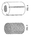
- An example of such a plug is shown diagrammatically in Fig. 3 .
- Each plug was placed in a mold that included elongated ribs that supported the plug by contacting the plug axially.
- the ribs were positioned at four locations that were evenly spaced around the circumference of the plug.
- Each ribs was approximately 0.050 inch high, creating a gap of 0.050 inch between the mold surface and the outer surface of the plug.
- the ribs were approximately 0.050 inch wide, and extended substantially the entire length of the plug.
- Poly-glyconate B polymer was then injection molded into and around each plug. Standard melt processing temperatures were used, i.e., 410-435°F. Using different plugs, injection molding was conducted at pressures of 600, 800, 900 and 1000 psi, to examine the effect of pressure on filling of the pores. At each molding pressure, the interconnecting pores were filled throughout the entire plug, and a 0.050 inch layer of polymer was provided around the implant in the areas where there was a gap between the mold and plug due to the presence of the supporting ribs. The outer surface of the plug was exposed in the areas where the ribs contacted the plug. A plug formed using this procedure is shown diagrammatically in Figs. 4 and 4A .
- Custom made flat-bottomed glass tubes (14 cm long x 24 mm ID) with a 24/29 quick fit tops were used for the polymerization.
- the tubes were washed with deionized water, dried in an oven at 105°C and allowed to cool in a desiccator.
- the tubes were filled with Dichlorodimethylsilane and sealed, then allowed to stand overnight with occasional shaking.
- the tubes were then emptied and rinsed three times with dry ether. After allowing the bulk of the residual ether to evaporate (5 mins) in the fume cupboard, the tubes were transferred to a vacuum oven at 150°C approx. 5 mbar.
- Tricalcium phosphate blocks were cut to produce cylinders that would fit in the reaction tubes using an Isomet low speed saw fitted with a diamond-watering blade using deionised water as a cutting fluid. The blocks were then rinsed with deionized water to remove any loose fragments of ceramic and dried in the vacuum oven at 105°C approx. 5 mbar for 2 hours.
- the dried ceramic blocks were placed in the reaction tubes, the tubes were sealed with suba seals vented with syringe needles.
- the vented tubes were then placed in the vacuum oven and a vacuum of approx 5 mbar was then applied.
- the oven was then re-pressurized with dry nitrogen and the tubes transferred to a conventional oven at 150°C shortly before they were to be used.
- the reaction tubes were processed in sets of up to 10 tubes.
- Pipe grips were used to remove cracked glass tube from sample.
- a Smart & Brown center lathe with a 3-jaw chuck was used.
- a high speed steel, right hand knife tool was used to turn the material down to the required diameter, initially a spindle speed of approx. 500 rpm but this was subsequently reduced to 250 rpm.
- the screw thread was cut using c a 50 rpm spindle speed and a H.S.S. tool 1.5mm wide and with a small radius on the end.
- a large pitch was selected 3.6mm and the depth was decided on looks only after a series of 0.2mm cuts were taken. No cutting fluid was used.
- the samples were tested in vivo by implantation into holes drilled into the cancellous bone of the distal femur and proximal tibia of 16 skeletally mature sheep.
- the samples were excised post-mortem, with the surrounding bone, at 6 weeks, 3 months, 6 months and 12 months (4 sheep at each time period), and examined histologically.
- Fig. 5 bone growth was observed at 6 months. Bone growth was completed by 12 months ( Fig. 5A ).
- the therapeutic additive may be provided in a physiologically acceptable carrier, and may be provided in sustained release or timed release formulations.
- the additives may also incorporate agents to facilitate their delivery, such as antibodies, antibody fragments, growth factors, hormones, or other targeting moieties, to which the additives are coupled.
- agents to facilitate their delivery such as antibodies, antibody fragments, growth factors, hormones, or other targeting moieties, to which the additives are coupled.
- Suitable carriers, additive dosages, and methods of incorporating the therapeutic additive are described, e.g., in U.S. Patent No. 6,337,198 .
- Suitable additives include biologically or pharmaceutically active compounds.
- biologically active compounds include cell attachment mediators, such as the peptide containing variations of the "RGD" integrin binding sequence known to affect cellular attachment, biologically active ligands, and substances that enhance or exclude particular varieties of cellular or tissue ingrowth.
- Such substances include, for example, osteoinductive substances, such as bone morphogenic proteins (BMP), epidermal growth factor (EGF), fibroblast growth factor (FGF), platelet-derived growth factor (PDGF), insulin-like growth factor (IGF-I and II), TGF-beta and the like.
- BMP bone morphogenic proteins
- EGF epidermal growth factor
- FGF fibroblast growth factor
- PDGF platelet-derived growth factor
- IGF-I and II insulin-like growth factor
- Examples of pharmaceutically active compounds include, for example, acyclovir, cephradine, malfalen, procaine, ephedrine, adriomycin, daunomycin, plumbagin, atropine, quanine, digoxin, quinidine, biologically active peptides, chlorin e.sub.6, cephalothin, proline and proline analogues such as cis-hydroxy-L-proline, penicillin V, aspirin, ibuprofen, steroids, nicotinic acid, chemodeoxycholic acid, chlorambucil, and the like.
- the additives may be used alone or in combination with other therapeutic or diagnostic agents.
- the composites discussed herein may be used in other applications, for example as materials for maxillo-facial reconstruction, and as bone graft substitutes, e.g. for spinal fusion or for void filling following bone loss due to tumor resection, trauma, joint replacement or other causes.
- the composites may also be used for repair and/or replacement for tissues such as cartilage, ligaments and tendons, and other soft tissue repair such as rotator cuff repair.
Landscapes
- Health & Medical Sciences (AREA)
- Chemical & Material Sciences (AREA)
- Veterinary Medicine (AREA)
- Animal Behavior & Ethology (AREA)
- Public Health (AREA)
- Life Sciences & Earth Sciences (AREA)
- General Health & Medical Sciences (AREA)
- Epidemiology (AREA)
- Engineering & Computer Science (AREA)
- Materials Engineering (AREA)
- Transplantation (AREA)
- Oral & Maxillofacial Surgery (AREA)
- Composite Materials (AREA)
- Dermatology (AREA)
- Medicinal Chemistry (AREA)
- Surgery (AREA)
- Inorganic Chemistry (AREA)
- Dispersion Chemistry (AREA)
- Orthopedic Medicine & Surgery (AREA)
- Cardiology (AREA)
- Biomedical Technology (AREA)
- Heart & Thoracic Surgery (AREA)
- Vascular Medicine (AREA)
- Materials For Medical Uses (AREA)
- Prostheses (AREA)
Abstract
Description
- This invention relates to tissue repair and replacement, and more particularly to methods and devices for repairing and/or replacing hard and soft tissue, e.g., orthopedic fixation devices, bone graft substitute materials, and wound dressings.
- The development of materials for tissue fixation devices has proceeded rapidly in recent years. The use of biodegradable polymers in such devices has provided surgeons with a safe alternative to metallic implants, potentially reducing adverse tissue response and eliminating the presence of a permanent tissue defect or the need to surgically remove the implant.
- Ideally, biodegradable tissue fixation devices should provide long-term repair strength, complete healing of the defect site, and controlled resorption of the device by the body. Biodegradable tissue fixation devices should have sufficient mechanical strength to withstand loads encountered during the healing process, while also providing an open "scaffold" structure that allows full bone ingrowth and remodeling.
- Thermally-induced phase separation of polymer solutions and blends has been used to form porous biodegradable scaffolds for tissue engineering (see, e.g., J Biomed Mater Res, 47:8-17, 1999 and J Biomed Mater Res 60:20-29, 2002.) For example, polymeric scaffolds may be formed by heat treating a blend of soluble and insoluble polymers to increase phase separation, and then dissolving the soluble polymer to leave a porous scaffold of the insoluble polymen These scaffolds are formed prior to implantation, i.e., the scaffold is porous when it is implanted into a patient.
- Porous ceramic materials, e.g., porous calcium phosphate ceramics, have been used as bone graft substitutes. While these materials may promote bone cell attachment and infiltration, they are typically brittle, and thus may not possess the mechanical strength needed for use in tissue fixation devices.
-
WO 02/15881 WO 97/45147 - In general, the invention features biodegradable tissue fixation devices that are substantially non-porous prior to implantation, providing a mechanically robust anchor during implantation and initial use. By "substantially non-porous," we mean that the mechanical strength of the device is not compromised by any porosity, as compared to the mechanical strength of a similar device of the same material having no porosity, i.e., being fully dense. Generally, the compressive strength of the device, as measured by ASTM D695, is at least 80% of that of a similar device formed of fully dense material. Typically, the devices, when initially implanted, do not have sufficient porosity to support tissue ingrowth.
- The tissue fixation devices include at least two components having different relative rates of in vivo degradation. The components form co-continuous interpenetrating phases so that, after the device is implanted in a patient, the faster-degrading component degrades in vivo leaving a macro-porous scaffold formed of the other component. The scaffold has pores into which tissue, e.g., bone, can infiltrate, allowing good tissue ingrowth and remodeling. The component that forms the scaffold may be relatively non-degradable, or may eventually degrade.
- The invention features a tissue fixation device that includes two interpenetrating ceramic materials, one ceramic material having a higher rate of in vivo degradation than the other.
- The devices discussed above may have one or more of the following advantages.
- The devices are initially non-porous and so have good strength and stiffness, enabling them to function well in use. In some implementations, the device may have a compressive strength (ASTM D695) of at least 10 MPa. When the devices degrade in vivo, the pores within the resulting scaffold are above the size required for tissue ingrowth, facilitating in-growth of bone or other tissue into the device. This tissue ingrowth, especially in the case of bone, will enhance the strength of the repair.
- The slow-degrading component that forms the scaffold maintains the mechanical properties and functionality of the device, as the rapid-degrading component is replaced by ingrowing tissue. The scaffold material may subsequently degrade, leaving pores in the tissue that replaced the rapid-degrading component
- The porous structure of the scaffold allows a controlled release of breakdown products, which may prevent undesirable "burst release" of breakdown products.
- The devices described herein may be used to allow non-critical size bone defects to heal, e.g., by placing one of the devices in the non-critical size defect to fill the defect so that the unfilled area is of critical size allowing bone to grow across the defect.
- The term "erosion' as used herein includes surface erosion processes, in which degradation occurs first at a surface or end of the device and moves inwards as degradation progresses.
- The details of one or more embodiments of the invention are set forth in the accompanying drawings and the description below. Other features and advantages of the invention will be apparent from the description and drawings, and from the claims. Certain embodiments set out below do not from part of the present invention, but are noretheless relevant to an understanding of the present invention.
-
-
FIGS. 1 and 2 are SEM photomicrographs of a polymeric scaffold resulting from the procedures described in Reference Example 1. -
FIGS. 3 is a perspective view of a ceramic plug used in the procedure described in reference Example 3. -
FIGS. 4 and4A are perspective and cross-sectional views, respectively, of a device resulting from the procedure described in reference Example 3. -
FIGS. 5 and 5A are SEM photomicrographs of a device resulting from the procedures described in reference Example 4, showing bone ingrowth into the device during in vivo testing, at 6 and 12 months, respectively. - Biodegradable tissue fixation devices are provided that are initially substantially non-porous. The devices include two or more components, present as co-continuous interpenetrating phases, having different rates of in vivo degradation. After implantation, the faster-degrading component degrades first, leaving a porous scaffold of the slower-degrading component. The slower degrading component may then degrade, leaving pores in the in-growing tissue, or, in some cases, may remain intact for the life of the implanted device.
- As will be discussed in detail below, the device may include, for example, (i) two polymeric components; (ii) a polymeric component and a ceramic component, with the polymeric component being faster degrading and the ceramic component forming the scaffold, (iii) a polymeric component and a ceramic component, with the ceramic component being faster degrading and the polymeric component forming the scaffold; or (iv) two ceramic components. In the case of two polymeric components, the device may be formed by phase separation of a blend of immiscible polymers, or by initially forming a polymeric scaffold of a first polymer, and infiltrating the pre-formed scaffold with a second polymer. These various options will be discussed in turn below, but only devices according to option (iv) form part of the present invention as defined in the appended claims. Examples (i) to (iii) are provided as relevant technical information which may be applicable in general context to present invention
- As discussed above, initially non-porous biodegradable tissue fixation devices may be formed using a blend of two bioresorbable polymers with different rates of in vivo degradation. The two polymers are immiscible and have a co-continuous macroscopic phase-separated structure. Generally, the two polymers are insoluble in water or aqueous media, e.g., body fluids.
- Immiscible polymer blends, when melted, generally behave as an emulsion. However, due to the relatively high viscosity of the melted polymers, phase separation and inversion occurs only very slowly. This allows control of the size of the phases and production of co-continuous phase structures at compositions other than phase inversion point. If a well-mixed immiscible polymer blend is heated above its melting point its phases will slowly separate to produce a co-continuous or discontinuous phase structure.
- Generally, the phases should be substantially co-continuous, so that the pores produced during degradation will be interconnected. If the rapid-degrading phase is discontinuous, degradation products may not be able to escape from the scaffold and tissue may not be able to grow in. If the slow-degrading phase is discontinuous the scaffold produced when the polymer degrades may not have adequate structural integrity.
- The structure of the phases can be controlled by the choice of polymers, e.g., based on their miscibility, melt viscosities and molecular weights, and by the ratio of the polymers. The polymers and the ratio in which they are provided are selected so that a co-continuous phase separated structure is provided.
- The criteria for choosing a pair of polymers are that the two polymers (a) degrade at different rates, so that a porous scaffold is formed before the entire device degrades; and (b) be immiscible, so that they form two separate phases when mixed.
- Degradation rate can be quantified as the time required for 100 % mass loss. A particular component can serve as the fast-degrading component in one polymer blend, and yet serve as the slow-degrading component in a different polymer blend. For example, polyglyconates are fast-degrading compared to PLLA, but slow degrading compared to polyanhydrides. The table below shows some degradation rates (100% mass loss) for some common bioresorbable polymers. Degradation rates were tested according to ISO 15814 "Implants for Surgery - Copolymers and blends based on polylactide - In-vitro degradation". Briefly, this test method involves placing samples in phosphate buffer solution at pH 7.4 at 37 ° C. Samples are removed at desired time intervals and weighed to determine mass loss, mechanical properties, molecular weight etc. The test conditions are intended to simulate in vivo degradation.
Polymer Approx. time for Absorption (months) Polycaprolactone (PCL) >36 Poly-L-lactic acid (PLLA) 36-60 PLLA-co-GA 82:18 12-15 Poly-DL-lactic acid (PDLLA) 12 PLLA-co-DLLA 50:50 12 PGA-co-TMC ( Maxon B) 12 Polyglycolic acid (PGA) 6-12 Poly-p-dioxanone (PDS) 6 PDLLA-co-GA (85:15) 3-6 Polyanhydrides <3 - It is generally preferred that the times for complete absorption of the two polymers differ by at least 8 weeks, typically by about 12 weeks to two years. The difference in the degradation rates may be selected to provide a desired effect in vivo, e.g., rapid formation of a long-lasting scaffold, or rapid formation of a scaffold that will itself degrade relatively rapidly.
- Suitable polymers, which may serve as the slow or rapid-degrading polymer, include, for example: polyesters; polyphosphazenes; polyacetals; polyalkanoates; polyurethanes; poly(lactic acid) (PLA); poly(L-lactic acid) (PLLA); poly (DL-lactic acid); poly-DL-lactide-co-glycolide (PDLGA) ; poly(L-lactide-co-glycolide) (PLLGA); polycaprolactone (PCL); polyorthoesters; polycarbonates; ABA tri-block co-polymers with A blocks of semicrystalline polyglycolic acid (PGA) and a B block of amorphous trimethylene carbonate (TMC), also known as polyglyconates, commercially available from Polysciences under the tradename MAXON B polymers; and erodible polymers, e.g., polyanhydrides. Other biodegradable polymers may also be used. Typically, polymers that lose 100% of their mass within 12 months are considered to be rapid-degrading. It is generally preferred that both polymers be thermoplastic, so that devices can be produced by conventional polymer processing techniques such as injection molding.
- Generally, the slow-degrading polymer and rapid-degrading polymer are provided in a ratio of from about 80:20 to 20:80, e.g., from about 60:40 to 40:60. The composition at which a blend of immiscible polymers will be co-continuous is known as the "phase inversion point"; generally, for all other compositions of this blend of polymers, one phase will become continuous with the other dispersed within it. The volume ratio of the phase inversion point for a mixture of immiscible liquids can be predicted from the ratio of their viscosities according to the following equation, which expresses the relationship of volume ratio at phase inversion to phase viscosity:

- η = Viscosity of polymer
- ϕ = Volume fraction of polymer
- Other factors having an effect on the morphology of the blend are the interfacial tension between the phases and the mixing conditions. Immiscible polymers will generally separate in the melt to produce two phases, a well-mixed blend forming an emulsion. The stability, phase distribution and other properties of the emulsion can be predicted from theory, if the physical properties of its components are known. Due to the high melt viscosity of polymers, changes in emulsion structure are slow, so little change in phase structure is observed during conventional extrusion or injection molding. By heating the polymer mixture above its melting point for an extended period of time, significant large-scale phase separation (50 to 1000µm) can be achieved. The extent of phase separation can be controlled by varying the treatment time and temperature. We have found that due to the slow separation rate it is possible to produce and fix (by cooling below the melting point) co-continuous phase structures at compositions other than that of the phase inversion point.
- Additives may be incorporated into either or both of the phases to modify the melt viscosity and/or biocompatibilty of the polymer, e.g., fillers such as hydroxyapatite or other calcium phosphates. Additives may be added to either or both of the polymer phases to modify the degradation rate of that phase, e.g., lauric acid. Blends of miscible polymers may also be used in one or more of the phases to achieve the desired properties.
- Alternatively, devices including two polymeric components may be formed by infiltrating a porous, pre-formed polymeric structure with (i) a resorbable polymer, and/or (ii) reactive components (i.e. monomers, oligomers etc) which on initiation of a chemical reaction form a degradable polymeric matrix. In either case, one component is either non-degrading or slow-degrading in vivo (slower than the other components). Thus, as discussed above, the device is initially non-porous and thus mechanically robust, but forms an open polymeric scaffold as the faster degrading polymer degrades in vivo.
- In this embodiment, the two polymers need not be immiscible, but need only have different degradation rates. Infiltration may be accomplished, for example, using techniques that will be described below under "Polymer-Ceramic Systems."
- Initially non-porous, biodegradable tissue fixation/repair devices that provide a ceramic scaffold may be formed by infiltrating a porous, pre-formed ceramic structure with (i) a resorbable polymer and/or (ii) reactive components (i.e. monomers, oligomers etc) which on initiation of a chemical reaction form a degradable polymeric matrix. In either case, the porous ceramic structure is either non-degrading or slow-degrading in vivo (slower than the infiltrating polymer or reactive components).
- The polymer ceramic device is designed so that the polymeric phase will degrade preferentially, to produce a ceramic scaffold that fills with bone or other tissue. The ceramic phase may also subsequently degrade, resulting in the complete replacement of the device by bone or other tissue. The device will thus eventually either be replaced completely by bone, or be replaced partially by bone, to yield a bone-filled ceramic scaffold.
- The mode of degradation of the polymer will also influence the structure that is formed in situ. Mode of degradation will generally fall into one of the following categories: (i) the polymer bulk degrades to form an open ceramic scaffold, which then fills with bone; in this model bone does not grow into the ceramic structure until most of the polymer has degraded; or (ii) the polymer surface erodes to generate pores which bone grows into; in this model bone will supplement the strength of the device by replacing polymer as the polymer degrades.
- Suitable polymers capable of fully infiltrating the macro- and micro-pores of the pre-formed porous ceramic structure include but are not limited to: Poly(α-hydroxy acids), e.g., (polylactides, polyglycolides, polycaprolacatones, polydioxanones,) polyhydroxyalkonates, polycarbonates, polyacetals, polyorthoesters, polyamino acids, polyphosphoesters, polyesteramides, polyfumerates, polyanhydrides, polycyanoacrylates, polyoxomers, polysaccharides, collagen, and polyurethanes. These polymers may take the form of homopolymers or copolymers (i.e. random, block) or blends thereof. The polymer can have any desired structure, e.g., linear, star, branched and the like. Examples of suitable polymer and ceramic combinations, chosen so that the polymer will degrade faster than the ceramic, include Polyglyconate B with tricalcium phosphate (TCP), and PLA with hydroxyapatite (HA).
- Suitable reactive monomers/oligomers include those typically used to form the above polymers, for example cyclic esters, e.g., lactides, glycolides and caprolactone, cyclic carbonates, divinyl ethers-diols, disocyanate-diamine, and the like. Suitable monomers typically melt to produce a water-like consistency, i.e., the monomers have very low melt viscosities. Thus, generally little or no solvent is required to moderate the melt viscosity of the monomer, and the monomer is able to penetrate completely into the pores of the ceramic scaffold.
- The ceramic preform should have sufficient structural integrity to withstand infiltration by the polymer or reactive monomers/oligomers and to provide desired structural properties in situ as the polymer degrades and tissue ingrowth occurs. In some implementations, the preform has a compression strength of at least 1 MPa, e.g., at least 3 MPa.
- The polymer and/or reactive monomers/oligomers can be infiltrated into the ceramic preform using any desired technique, for example by injection molding or reactive processing. Molding pressures may be adjusted to avoid damage to the preform and to ensure adequate infiltration. Typical molding pressures are from about 500 to 2000 psi.
- Alternatively, the polymer/ceramic composites discussed above may be designed so that the ceramic degrades preferentially in vivo, rather than the polymer, resulting in a polymeric scaffold. The ceramic surface erodes (by dissolution, or by being eroded by cells) to generate pores which bone grows into. This model allows bone to supplement the strength of the device by replacing ceramic as it degrades. To achieve this, a polymer/ceramic combination is selected in which the ceramic will have a more rapid degradation rate than the polymer. The polymer phase may also subsequently degrade, resulting in complete replacement of the device by bone or other tissue.
- Suitable polymers capable of fully infiltrating the macro- and micro-pores of the pre-formed porous structure include the polymers discussed above in the "Ceramic Scaffolds from Polymer/Ceramic Composites" section. Examples of suitable polymer and ceramic combinations, chosen so that the ceramic will degrade faster than the polymer, include PLA with TCP and PCL with TCP.
- Suitable reactive monomers/oligomers include those discussed above in the "Ceramic Scaffolds from Polymer/Ceramic Composites" section.
- Initially non-porous, biodegradable tissue fixation/repair devices that provide a ceramic scaffold may also be formed by infiltrating a porous, pre-formed ceramic structure with a ceramic material that forms a degradable ceramic matrix. One component is either non-degrading or slow-degrading in vivo (slower than the other component).
- Suitable ceramics include calcium phosphates such as hydroxy apatite, tricalcium phosphate, octacalcium phosphate, dicalcium phosphate dihydrate; calcium sulfate; beta dicalcium pyrophosphate; and calcium carbonate. Other suitable ceramics include biocompatible glasses such as Bioglass. Examples of suitable combinations include hydroxyapatite with tricalcium phosphate, hydroxyapatite with calcium sulfate, tricalcium phosphate with calcium sulfate (in these examples the first material is the slower degrading component). The composites can be made by infiltrating a porous pre-formed structure formed of one ceramic with the other ceramic component in the form of a slurry. This second component may be a ceramic in a settable cement form e.g. calcium sulfate (plaster of Paris).
- Generally, preferred scaffolds have a pore size of about 20-2000 microns, preferably about 50-1000 microns, and a porosity of about 10-90%, preferably about 50-85%. The degradable ceramic used to infiltrate the scaffold preferably has a particle size that is sufficiently large to allow cell infiltration, typically less than 100 µm. The particle size of the ceramic used to form the scaffold is typically from about 1 nm to 1 mm.
- The following examples are intended to be illustrative and not limiting in effect.
- 50 grams each of PGA and PLLA were dried under vacuum at 110°C overnight. The polymer granules were then dry mixed before use. A twin-screw extruder was used to melt mix the polymer at 245°C. The blend was extruded in the form of a
rod 6 mm in diameter. - 2 cm lengths of the polymer rod were subjected to melt induced phase expansion (MIPE) treatment in a heated press at 230°C or 235°C in a cylindrical mold (6mm diameter, 20mm long). The mold was placed in the press and the press closed with a force of 50 kN. Once the sample had received the required treatment time, the mold was removed from the press and immersed in cold water to rapidly cool the sample. The treated rods were approximately 5.7 mm in diameter due to shrinkage on cooling. The rods were cut to produce a series of 1mm thick slices using a diamond bladed saw.
- Slices of each sample were subject to accelerated degradation in PBS at 70°C. After 29 days, the samples were removed from the PBS, rinsed with deionised water and dried in a vacuum oven at 110°C. The samples were then examined by SEM to reveal the porous structure generated by the PGA degrading out of the PLLA. The dimensions of the pores produced were between 1 and 200 µm depending on the MIPE treatment conditions; examples of the porosity observed are shown in
Figs. 1 and 2 . The pore size was observed to increase in size with MIPE treatment temperature and time. - 5 grams of PLLA were placed in a small (15 ml) membrane filter housing with no membrane fitted. The granules were washed with 2 x 10 ml of CH2Cl2 and the residual solvent removed by applying a vacuum to the filter. The wet granules were packed into a 30 ml pot, to produce a pellet molded to the shape of the pot, then placed in an oven at 60°C. After 1 hour, the samples were transferred to a vacuum oven and heated to 100°C at 5 mbar for 2 hours. The samples were then left under vacuum over night. The cylindrical blocks (24 mm diameter by 14 mm) produced had a porosity of 49 ± 5 %(v/v) with pore dimensions of 0.5 to 3.5 mm.
- Poly(sebacic anhydride) (PSA) was melted in an oven at 120°C. Two porous PLLA blocks were placed in 30 ml PTFE pots then heated in an oven at 100°C, the liquid PSA then was poured into the pots containing the blocks. The filled pots were then transferred to a vacuum oven at 100°C and a vacuum of 0.87 mbar applied to remove any air bubbles. The samples were then removed from the oven and allowed to cool. Once the PSA had solidified, the composite samples were removed from the pots and cut using a precision diamond saw to produce slices 4 mm thick.
Slices of composite were placed in PBS at 37°C, for up to 75 days. The PSA was observed to erode out of the PLLA to leave pores of 0.5 to 3.5 mm. - A number of cylindrical plugs of hydroxy apatite were provided, each plug having interconnecting pores ranging from 100 to 1000 µm in diameter. An example of such a plug is shown diagrammatically in
Fig. 3 . - Each plug was placed in a mold that included elongated ribs that supported the plug by contacting the plug axially. The ribs were positioned at four locations that were evenly spaced around the circumference of the plug. Each ribs was approximately 0.050 inch high, creating a gap of 0.050 inch between the mold surface and the outer surface of the plug. The ribs were approximately 0.050 inch wide, and extended substantially the entire length of the plug.
- Poly-glyconate B polymer was then injection molded into and around each plug. Standard melt processing temperatures were used, i.e., 410-435°F. Using different plugs, injection molding was conducted at pressures of 600, 800, 900 and 1000 psi, to examine the effect of pressure on filling of the pores. At each molding pressure, the interconnecting pores were filled throughout the entire plug, and a 0.050 inch layer of polymer was provided around the implant in the areas where there was a gap between the mold and plug due to the presence of the supporting ribs. The outer surface of the plug was exposed in the areas where the ribs contacted the plug. A plug formed using this procedure is shown diagrammatically in
Figs. 4 and4A . - Custom made flat-bottomed glass tubes (14 cm long x 24 mm ID) with a 24/29 quick fit tops were used for the polymerization. The tubes were washed with deionized water, dried in an oven at 105°C and allowed to cool in a desiccator. The tubes were filled with Dichlorodimethylsilane and sealed, then allowed to stand overnight with occasional shaking. The tubes were then emptied and rinsed three times with dry ether. After allowing the bulk of the residual ether to evaporate (5 mins) in the fume cupboard, the tubes were transferred to a vacuum oven at 150°C approx. 5 mbar.
- All other glassware, stoppers, seals and equipment used with reagents was washed with deionized water, dried at 105°C and stored in a desiccator prior to use.
- All preparation was done under a dry nitrogen atmosphere in an Atmosbag. 1.00g of SnCl2.2H2O and 2.91 g (2.60ml) of Di(ethyleneglycol) were weighed into a 10 ml Wheaton vial. The vial was sealed prior to removal from the Atmosbag, and shaken to produce a clear solution.
- Tricalcium phosphate blocks were cut to produce cylinders that would fit in the reaction tubes using an Isomet low speed saw fitted with a diamond-watering blade using deionised water as a cutting fluid. The blocks were then rinsed with deionized water to remove any loose fragments of ceramic and dried in the vacuum oven at 105°C approx. 5 mbar for 2 hours.
- The dried ceramic blocks were placed in the reaction tubes, the tubes were sealed with suba seals vented with syringe needles. The vented tubes were then placed in the vacuum oven and a vacuum of approx 5 mbar was then applied. The oven was then re-pressurized with dry nitrogen and the tubes transferred to a conventional oven at 150°C shortly before they were to be used. The reaction tubes were processed in sets of up to 10 tubes.
- 10µl of catalyst/ initiator solution was added to each tube, with the monomer, after which the tubes were placed in an oven at 150°C. Once the monomer had melted, the tubes were filled and sealed under a dry nitrogen atmosphere in an Atmos bag. Before the tubes had cooled, with the monomer still liquid, the tubes were vented with syringe needles and placed in a preheated vacuum oven at 150°C. A vacuum of approx. 5 mbar was then applied for 15 minutes to ensure that all air bubbles were removed from the ceramic. The oven was then re-pressurized with dry nitrogen, the tubes removed and the syringe needles taken out immediately. The tubes were then placed in a conventional oven at 147 °C (oven set at 155°C). The samples were left in the oven for approx. 5.5 days; the oven was then switched off and the samples allowed to cool. The samples were then bagged up under dry nitrogen and placed in the freezer.
- Pipe grips were used to remove cracked glass tube from sample. A Smart & Brown center lathe with a 3-jaw chuck was used. A high speed steel, right hand knife tool was used to turn the material down to the required diameter, initially a spindle speed of approx. 500 rpm but this was subsequently reduced to 250 rpm. The screw thread was cut using c a 50 rpm spindle speed and a H.S.S. tool 1.5mm wide and with a small radius on the end. A large pitch was selected 3.6mm and the depth was decided on looks only after a series of 0.2mm cuts were taken. No cutting fluid was used.
- The samples were tested in vivo by implantation into holes drilled into the cancellous bone of the distal femur and proximal tibia of 16 skeletally mature sheep. The samples were excised post-mortem, with the surrounding bone, at 6 weeks, 3 months, 6 months and 12 months (4 sheep at each time period), and examined histologically. As shown in
Fig. 5 , bone growth was observed at 6 months. Bone growth was completed by 12 months (Fig. 5A ). - The therapeutic additive may be provided in a physiologically acceptable carrier, and may be provided in sustained release or timed release formulations. The additives may also incorporate agents to facilitate their delivery, such as antibodies, antibody fragments, growth factors, hormones, or other targeting moieties, to which the additives are coupled. Suitable carriers, additive dosages, and methods of incorporating the therapeutic additive are described, e.g., in
U.S. Patent No. 6,337,198 . - Suitable additives include biologically or pharmaceutically active compounds. Examples of biologically active compounds include cell attachment mediators, such as the peptide containing variations of the "RGD" integrin binding sequence known to affect cellular attachment, biologically active ligands, and substances that enhance or exclude particular varieties of cellular or tissue ingrowth. Such substances include, for example, osteoinductive substances, such as bone morphogenic proteins (BMP), epidermal growth factor (EGF), fibroblast growth factor (FGF), platelet-derived growth factor (PDGF), insulin-like growth factor (IGF-I and II), TGF-beta and the like.
- Examples of pharmaceutically active compounds include, for example, acyclovir, cephradine, malfalen, procaine, ephedrine, adriomycin, daunomycin, plumbagin, atropine, quanine, digoxin, quinidine, biologically active peptides, chlorin e.sub.6, cephalothin, proline and proline analogues such as cis-hydroxy-L-proline, penicillin V, aspirin, ibuprofen, steroids, nicotinic acid, chemodeoxycholic acid, chlorambucil, and the like.
- The additives may be used alone or in combination with other therapeutic or diagnostic agents.
- While bone fixation devices are discussed above, the composites discussed herein may be used in other applications, for example as materials for maxillo-facial reconstruction, and as bone graft substitutes, e.g. for spinal fusion or for void filling following bone loss due to tumor resection, trauma, joint replacement or other causes. The composites may also be used for repair and/or replacement for tissues such as cartilage, ligaments and tendons, and other soft tissue repair such as rotator cuff repair.
Claims (13)
- A device for tissue repair or replacement, comprising first and second components having different relative rates of in vivo degradation, the first component having a higher rate of in vivo degradation than the second component, and the first and second components being arranged relative to each other so that, after implantation of the device, the first component degrades in vivo leaving a scaffold formed of the second component, the scaffold having pores into which tissue can infiltrate,
characterised in that the first and second components comprise a ceramic. - The device of claim 1 wherein the device is substantially non-porous prior to implantation into a patient.
- The device of claim 1 or 2 wherein there is at least an 8 week difference between the degradation rates of the components.
- The device of claim 3 wherein the degradation rates differ by about 12 months to 2 years.
- The device of any preceding claim wherein at least one of the components includes a therapeutic additive.
- The device of any preceding claim wherein the second component comprises a porous ceramic structure comprising a first ceramic; and the first component comprises a second ceramic disposed in pores of the ceramic structure, and wherein the device is substantially non-porous prior to implantation in a patient.
- The device of any preceding claim wherein the ceramic structure has a pore size of about 20 to 2000 microns.
- The device of any preceding claim wherein the ceramic structure has a porosity of about 10 to 90%.
- A method of making a device for tissue repair or replacement, the device comprising first and second components having different relative rates of in vivo degradation, the first component having a higher rate of in vivo degradation than the second component, the method comprising arranging the first and second components relative to each other so that, after implantation of the device, the first component degrades in vivo leaving a scaffold formed of the second component, the scaffold having pores into which tissue can infiltrate,
characterised in that the first and second components comprise a ceramic. - The method of claim 9 wherein the arranging step comprises forming a porous scaffold of a first component, and infiltrating the porous scaffold with a second component.
- The method of claim 10 wherein the scaffold is infiltrated with a sufficient amount of the second component to render the device substantially non-porous.
- The method of claim 10 or 11 wherein the infiltrating step comprises providing the second component in the form of a liquid.
- The method of any one of claims 10 to 12 wherein the infiltrating step comprises injection moulding.
Applications Claiming Priority (2)
| Application Number | Priority Date | Filing Date | Title |
|---|---|---|---|
| US10/645,962 US8529625B2 (en) | 2003-08-22 | 2003-08-22 | Tissue repair and replacement |
| PCT/US2004/027309 WO2005018700A1 (en) | 2003-08-22 | 2004-08-20 | Tissue repair and replacement |
Publications (2)
| Publication Number | Publication Date |
|---|---|
| EP1656166A1 EP1656166A1 (en) | 2006-05-17 |
| EP1656166B1 true EP1656166B1 (en) | 2011-11-09 |
Family
ID=34194423
Family Applications (1)
| Application Number | Title | Priority Date | Filing Date |
|---|---|---|---|
| EP04781909A Expired - Lifetime EP1656166B1 (en) | 2003-08-22 | 2004-08-20 | Tissue repair and replacement |
Country Status (6)
| Country | Link |
|---|---|
| US (5) | US8529625B2 (en) |
| EP (1) | EP1656166B1 (en) |
| JP (1) | JP5085128B2 (en) |
| AT (1) | ATE532541T1 (en) |
| AU (2) | AU2004266150B2 (en) |
| WO (1) | WO2005018700A1 (en) |
Cited By (1)
| Publication number | Priority date | Publication date | Assignee | Title |
|---|---|---|---|---|
| US9314550B2 (en) | 2012-02-01 | 2016-04-19 | Bioenergy Capital Ag | Implant matrix made of a polymer mixture |
Families Citing this family (52)
| Publication number | Priority date | Publication date | Assignee | Title |
|---|---|---|---|---|
| US7303817B2 (en) | 2001-10-24 | 2007-12-04 | Weitao Jia | Dental filling material |
| US7204874B2 (en) * | 2001-10-24 | 2007-04-17 | Pentron Clinical Technologies, Llc | Root canal filling material |
| US7750063B2 (en) | 2001-10-24 | 2010-07-06 | Pentron Clinical Technologies, Llc | Dental filling material |
| US7211136B2 (en) * | 2001-10-24 | 2007-05-01 | Pentron Clinical Technologies, Llc | Dental filling material |
| US7204875B2 (en) * | 2001-10-24 | 2007-04-17 | Pentron Clinical Technologies, Llc | Dental filling material |
| US20040254640A1 (en) * | 2002-03-01 | 2004-12-16 | Children's Medical Center Corporation | Needle punched textile for use in growing anatomical elements |
| US20050251267A1 (en) * | 2004-05-04 | 2005-11-10 | John Winterbottom | Cell permeable structural implant |
| US9107751B2 (en) * | 2002-12-12 | 2015-08-18 | Warsaw Orthopedic, Inc. | Injectable and moldable bone substitute materials |
| US8529625B2 (en) | 2003-08-22 | 2013-09-10 | Smith & Nephew, Inc. | Tissue repair and replacement |
| US8012210B2 (en) * | 2004-01-16 | 2011-09-06 | Warsaw Orthopedic, Inc. | Implant frames for use with settable materials and related methods of use |
| WO2005114322A2 (en) * | 2004-05-12 | 2005-12-01 | Massachusetts Institute Of Technology | Manufacturing process, such as three-dimensional printing, including solvent vapor filming and the like |
| EP2594259A1 (en) | 2004-08-04 | 2013-05-22 | Brookwood Pharmaceuticals, Inc. | Methods for manufacturing delivery devices and devices thereof |
| US7722895B1 (en) * | 2004-09-20 | 2010-05-25 | Warsaw Orthopedic, Inc. | Osteogenic implants with combined implant materials, and materials and methods for same |
| US8545866B2 (en) | 2004-10-29 | 2013-10-01 | Smith & Nephew, Inc. | Bioabsorbable polymers |
| ATE424862T1 (en) * | 2004-10-29 | 2009-03-15 | Smith & Nephew Inc | BIOABSORBABLE POLYMERS WITH CALCIUM CARBONATE |
| WO2007084609A2 (en) * | 2006-01-19 | 2007-07-26 | Osteotech, Inc. | Porous osteoimplant |
| EP2010597B1 (en) * | 2006-04-07 | 2015-06-17 | The University of Queensland | Porous polymer blend structures |
| WO2007115368A1 (en) * | 2006-04-07 | 2007-10-18 | The University Of Queensland | Porous polymer structures |
| EP3061791B1 (en) | 2006-07-20 | 2019-01-16 | OrbusNeich Medical, Inc. | Bioabsorbable polymeric composition for a medical device |
| CN100391551C (en) * | 2006-10-19 | 2008-06-04 | 浙江大学 | Preparation method of carbon fiber reinforced polylactic acid/hydroxyapatite composite material |
| EP2073754A4 (en) | 2006-10-20 | 2012-09-26 | Orbusneich Medical Inc | Bioabsorbable polymeric composition and medical device background |
| US7959942B2 (en) | 2006-10-20 | 2011-06-14 | Orbusneich Medical, Inc. | Bioabsorbable medical device with coating |
| GB0702847D0 (en) * | 2007-02-14 | 2007-03-28 | Smith & Nephew | Scaffold with increased pore size |
| EP2014256A1 (en) | 2007-07-12 | 2009-01-14 | Straumann Holding AG | Composite bone repair material |
| US20090036996A1 (en) * | 2007-08-03 | 2009-02-05 | Roeber Peter J | Knit PTFE Articles and Mesh |
| US20090187197A1 (en) * | 2007-08-03 | 2009-07-23 | Roeber Peter J | Knit PTFE Articles and Mesh |
| US8124601B2 (en) * | 2007-11-21 | 2012-02-28 | Bristol-Myers Squibb Company | Compounds for the treatment of Hepatitis C |
| CA2709712C (en) | 2007-12-20 | 2016-05-10 | Surmodics Pharmaceuticals, Inc. | Process for preparing microparticles having a low residual solvent volume |
| CA2711847C (en) * | 2008-01-09 | 2018-05-08 | Innovative Health Technologies, Llc | Implant pellets and methods for performing bone augmentation and preservation |
| US20090248162A1 (en) * | 2008-03-25 | 2009-10-01 | Warsaw Orthopedic, Inc. | Microparticle delivery syringe and needle for placing suspensions and removing vehicle fluid |
| WO2010138212A2 (en) | 2009-05-29 | 2010-12-02 | Incube Labs, Llc | Biodegradable medical implants, polymer compositions and methods of use |
| US9399086B2 (en) * | 2009-07-24 | 2016-07-26 | Warsaw Orthopedic, Inc | Implantable medical devices |
| JP5675820B2 (en) * | 2009-09-22 | 2015-02-25 | エボニック コーポレイションEvonik Corporation | Implant devices with various bioactive agent loading configurations |
| CN101703804B (en) * | 2009-11-25 | 2013-03-13 | 复旦大学附属中山医院 | Porous bone replacing material for control release of antibioticsand preparation method thereof |
| EP2623134A1 (en) * | 2012-02-01 | 2013-08-07 | Phrontier S.A.R.L. | Implant matrix from a polymer mixture |
| CA2913845A1 (en) * | 2013-05-23 | 2014-11-27 | Ceramtec Gmbh | Component consisting of ceramics comprising pore channels |
| US10682442B2 (en) | 2014-04-04 | 2020-06-16 | University Of Kentucky Research Foundation | Small molecule drug release from in situ forming degradable scaffolds incorporating hydrogels and bioceramic microparticles |
| DE102014117109A1 (en) * | 2014-11-21 | 2016-05-25 | Merz Dental Gmbh | Method for positional positioning of a semifinished product, method for producing a semifinished product for reproducible positional positioning and a suitable semi-finished product and a corresponding use thereof |
| ES2577883B2 (en) * | 2014-12-16 | 2016-11-21 | Universitat Politècnica De València | Biohybrid for use in the regeneration of neural tracts |
| US10420597B2 (en) | 2014-12-16 | 2019-09-24 | Arthrex, Inc. | Surgical implant with porous region |
| ES2973211T3 (en) * | 2016-05-02 | 2024-06-19 | Univ Marquette | Reinforced bone scaffold |
| WO2017192632A1 (en) | 2016-05-03 | 2017-11-09 | Additive Orthopaedics, LLC | Bone fixation device and method of use |
| WO2017210688A1 (en) | 2016-06-03 | 2017-12-07 | Additive Orthopaedics, LLC | Bone fixation devices |
| WO2018023131A1 (en) | 2016-07-29 | 2018-02-01 | Additive Orthopaedics, LLC | Bone fixation device and method of use |
| CN106957405B (en) * | 2017-04-07 | 2019-07-12 | 重庆大学 | A kind of preparation method and products thereof of ceramic toughening polymer HA-PDLLA-PUU |
| US10786370B2 (en) | 2017-12-28 | 2020-09-29 | Industrial Technology Research Institute | Cartilage repair implant, auxiliary surgical tool kit and cartilage repair system |
| US11147679B2 (en) | 2018-02-05 | 2021-10-19 | Paragon Advanced Technologies, Inc. | Bone fixation device |
| CN108578787A (en) * | 2018-08-07 | 2018-09-28 | 宁波宝亭生物科技有限公司 | A kind of absorbable bone anchoring device and preparation method thereof |
| TWI700080B (en) * | 2018-12-06 | 2020-08-01 | 可成生物科技股份有限公司 | Intervertebral disc repair device |
| CN110218423A (en) * | 2019-06-03 | 2019-09-10 | 东华镜月(苏州)纺织技术研究有限公司 | A kind of three-dimensional porous compound Monolithic Columns of polylactic acid and caprolactone and preparation method thereof |
| CN114767945A (en) * | 2022-03-14 | 2022-07-22 | 上海浩渤医疗科技有限公司 | Ribbon for fixing comminuted fracture block and preparation method thereof |
| CN116370708B (en) * | 2023-01-15 | 2024-07-19 | 北京化工大学 | Rotator cuff patch with piezoelectric effect and preparation method thereof |
Family Cites Families (43)
| Publication number | Priority date | Publication date | Assignee | Title |
|---|---|---|---|---|
| US4103002A (en) * | 1977-02-08 | 1978-07-25 | Board Of Regents, University Of Florida | Bioglass coated A1203 ceramics |
| DE2905878A1 (en) * | 1979-02-16 | 1980-08-28 | Merck Patent Gmbh | IMPLANTATION MATERIALS AND METHOD FOR THEIR PRODUCTION |
| US4619655A (en) * | 1984-01-26 | 1986-10-28 | University Of North Carolina | Plaster of Paris as a bioresorbable scaffold in implants for bone repair |
| JPS62202884A (en) * | 1986-02-28 | 1987-09-07 | 工業技術院長 | Live body substitute ceramic material |
| US4849285A (en) * | 1987-06-01 | 1989-07-18 | Bio Med Sciences, Inc. | Composite macrostructure of ceramic and organic biomaterials |
| US5681572A (en) * | 1991-10-18 | 1997-10-28 | Seare, Jr.; William J. | Porous material product and process |
| US6376573B1 (en) * | 1994-12-21 | 2002-04-23 | Interpore International | Porous biomaterials and methods for their manufacture |
| AU2759397A (en) | 1996-05-28 | 1998-01-05 | 1218122 Ontario Inc. | Resorbable implant biomaterial made of condensed calcium phosphate particles |
| FR2749756B1 (en) * | 1996-06-14 | 1998-09-11 | Bioland | PROCESS FOR THE PREPARATION OF AN IMPLANTABLE COMPOSITE MATERIAL, MATERIAL OBTAINED, IMPLANT COMPRISING SUCH MATERIAL, AND IMPLEMENTATION KIT |
| PT101973B (en) | 1997-02-26 | 2002-10-31 | B E M Biomateriais Electronica | CERAMIC COVERINGS WITH VARIOUS BIO-ACTIVITY AND COMPOSITION INTENDED FOR BIOMEDICAL APPLICATIONS IN PROTESES AND IMPLANTS |
| GB9704749D0 (en) * | 1997-03-07 | 1997-04-23 | Univ London | Tissue Implant |
| US5977204A (en) | 1997-04-11 | 1999-11-02 | Osteobiologics, Inc. | Biodegradable implant material comprising bioactive ceramic |
| US6071982A (en) | 1997-04-18 | 2000-06-06 | Cambridge Scientific, Inc. | Bioerodible polymeric semi-interpenetrating network alloys for surgical plates and bone cements, and method for making same |
| GB9814609D0 (en) * | 1998-07-07 | 1998-09-02 | Smith & Nephew | Polymers |
| US20030114936A1 (en) * | 1998-10-12 | 2003-06-19 | Therics, Inc. | Complex three-dimensional composite scaffold resistant to delimination |
| US6110484A (en) * | 1998-11-24 | 2000-08-29 | Cohesion Technologies, Inc. | Collagen-polymer matrices with differential biodegradability |
| US6103255A (en) * | 1999-04-16 | 2000-08-15 | Rutgers, The State University | Porous polymer scaffolds for tissue engineering |
| US6605293B1 (en) * | 1999-05-20 | 2003-08-12 | Trustees Of Boston University | Polymer re-inforced anatomically accurate bioactive protheses |
| US20030186005A1 (en) * | 1999-07-15 | 2003-10-02 | Andres Rivera | Applicator for a polymerizable monomer compound |
| ATE362777T1 (en) * | 1999-11-01 | 2007-06-15 | Osteobiologics Inc | BIODEGRADABLE POLYMER/CERAMIC IMPLANT MATERIAL WITH BIMODALEM DECOMPOSITION PROFILE |
| WO2001042333A2 (en) * | 1999-12-13 | 2001-06-14 | Michigan State University | Process for the preparation of polymers of dimeric cyclic esters |
| EP1286678A2 (en) | 2000-06-01 | 2003-03-05 | Sloan-Kettering Institute For Cancer Research | Combination of a mutant herpes virus and a chemotherapeutic agent for the treatment of cancer |
| GB0020610D0 (en) | 2000-08-21 | 2000-10-11 | Dytech Corp Ltd | Uses of porous carriers |
| US6599323B2 (en) * | 2000-12-21 | 2003-07-29 | Ethicon, Inc. | Reinforced tissue implants and methods of manufacture and use |
| US7005135B2 (en) * | 2001-01-30 | 2006-02-28 | Ethicon Inc. | Glass scaffolds with controlled resorption rates and methods for making same |
| US7122057B2 (en) * | 2001-04-12 | 2006-10-17 | Therics, Llc | Method and apparatus for engineered regenerative biostructures such as hydroxyapatite substrates for bone healing applications |
| US20020169066A1 (en) * | 2001-04-16 | 2002-11-14 | Cerabio, L.L.C. | Dense porous structures for use as bone substitutes |
| WO2003000480A1 (en) * | 2001-06-22 | 2003-01-03 | The Regents Of The University Of Michigan | Methods of designing and fabricating molds |
| US20030003127A1 (en) * | 2001-06-27 | 2003-01-02 | Ethicon, Inc. | Porous ceramic/porous polymer layered scaffolds for the repair and regeneration of tissue |
| US20030072790A1 (en) * | 2001-10-16 | 2003-04-17 | Industrial Technology Research Institute | Biodegradable porous devices for tissue engineering |
| US6955716B2 (en) * | 2002-03-01 | 2005-10-18 | American Dental Association Foundation | Self-hardening calcium phosphate materials with high resistance to fracture, controlled strength histories and tailored macropore formation rates |
| WO2003088925A2 (en) * | 2002-04-18 | 2003-10-30 | Carnegie Mellon University | Method of manufacturing hydroxyapatite and uses therefor in delivery of nucleic acids |
| US7166133B2 (en) * | 2002-06-13 | 2007-01-23 | Kensey Nash Corporation | Devices and methods for treating defects in the tissue of a living being |
| CA2428640A1 (en) * | 2002-06-25 | 2003-12-25 | Goodman Co., Ltd. | Biodegradable bioabsorbable material for clinical practice and method for producing the same |
| US20050163822A1 (en) * | 2002-06-25 | 2005-07-28 | Hiroyuki Shirahama | Biodegradable bio-absorbable material for clinical practice and method for producing the same |
| US20040002770A1 (en) * | 2002-06-28 | 2004-01-01 | King Richard S. | Polymer-bioceramic composite for orthopaedic applications and method of manufacture thereof |
| US7066962B2 (en) * | 2002-07-23 | 2006-06-27 | Porex Surgical, Inc. | Composite surgical implant made from macroporous synthetic resin and bioglass particles |
| TWI264313B (en) | 2002-08-07 | 2006-10-21 | Access Business Group Int Llc | Nonthermal plasma air treatment system |
| US7482355B2 (en) * | 2002-08-24 | 2009-01-27 | Astrazeneca Ab | Pyrimidine derivatives as modulators of chemokine receptor activity |
| US7393493B2 (en) | 2003-02-27 | 2008-07-01 | A Enterprises, Inc. | Crosslinkable polymeric materials and their applications |
| US8029755B2 (en) * | 2003-08-06 | 2011-10-04 | Angstrom Medica | Tricalcium phosphates, their composites, implants incorporating them, and method for their production |
| US8529625B2 (en) * | 2003-08-22 | 2013-09-10 | Smith & Nephew, Inc. | Tissue repair and replacement |
| CA2555586A1 (en) * | 2004-03-09 | 2005-09-22 | Osteobiologics, Inc. | Implant scaffold combined with autologous or allogenic tissue |
-
2003
- 2003-08-22 US US10/645,962 patent/US8529625B2/en not_active Expired - Fee Related
-
2004
- 2004-08-20 AU AU2004266150A patent/AU2004266150B2/en not_active Ceased
- 2004-08-20 WO PCT/US2004/027309 patent/WO2005018700A1/en not_active Ceased
- 2004-08-20 AT AT04781909T patent/ATE532541T1/en active
- 2004-08-20 JP JP2006524105A patent/JP5085128B2/en not_active Expired - Fee Related
- 2004-08-20 EP EP04781909A patent/EP1656166B1/en not_active Expired - Lifetime
-
2007
- 2007-01-30 US US11/668,497 patent/US20070129810A1/en not_active Abandoned
-
2010
- 2010-02-04 AU AU2010200401A patent/AU2010200401B2/en not_active Ceased
-
2013
- 2013-08-07 US US13/961,445 patent/US20130323402A1/en not_active Abandoned
- 2013-08-07 US US13/961,507 patent/US8992614B2/en not_active Expired - Fee Related
-
2015
- 2015-02-25 US US14/631,738 patent/US9504574B2/en not_active Expired - Fee Related
Cited By (1)
| Publication number | Priority date | Publication date | Assignee | Title |
|---|---|---|---|---|
| US9314550B2 (en) | 2012-02-01 | 2016-04-19 | Bioenergy Capital Ag | Implant matrix made of a polymer mixture |
Also Published As
| Publication number | Publication date |
|---|---|
| WO2005018700A1 (en) | 2005-03-03 |
| US20050042253A1 (en) | 2005-02-24 |
| JP5085128B2 (en) | 2012-11-28 |
| EP1656166A1 (en) | 2006-05-17 |
| AU2010200401B2 (en) | 2012-12-06 |
| US8992614B2 (en) | 2015-03-31 |
| US20130323294A1 (en) | 2013-12-05 |
| US20070129810A1 (en) | 2007-06-07 |
| US20150164643A1 (en) | 2015-06-18 |
| ATE532541T1 (en) | 2011-11-15 |
| US8529625B2 (en) | 2013-09-10 |
| US9504574B2 (en) | 2016-11-29 |
| US20130323402A1 (en) | 2013-12-05 |
| AU2010200401A1 (en) | 2010-02-25 |
| JP2007503226A (en) | 2007-02-22 |
| AU2004266150A1 (en) | 2005-03-03 |
| AU2004266150B2 (en) | 2010-09-09 |
Similar Documents
| Publication | Publication Date | Title |
|---|---|---|
| AU2010200401B2 (en) | Tissue repair and replacement | |
| US8715366B2 (en) | Porous and nonporous materials for tissue grafting and repair | |
| US5397572A (en) | Resorbable materials based on independently gelling polymers of a single enantiomeric lactide | |
| EP1357863A2 (en) | Compositions and methods for biomedical applications | |
| Lewandrowski et al. | Effect of a poly (propylene fumarate) foaming cement on the healing of bone defects | |
| CA2924317A1 (en) | Bioactive flowable wash-out resistant bone graft material and method for production thereof | |
| US20150265745A1 (en) | Porous and Nonporous Materials for Tissue Grafting and Repair | |
| Chen et al. | Reconstruction of calvarial defect using a tricalcium phosphate-oligomeric proanthocyanidins cross-linked gelatin composite | |
| US10105207B2 (en) | Porous and nonporous materials for tissue grafting and repair | |
| JP2023512533A (en) | A bioabsorbable implant with internal and external absorbability for the purpose of further improving bone growth and tissue bonding, and a method for manufacturing the same | |
| Huang et al. | Repair of bone defect in caprine tibia using a laminated scaffold with bone marrow stromal cells loaded poly (L‐lactic acid)/β‐tricalcium phosphate | |
| RU2327709C2 (en) | Method of obtaining porous polymer biodegradable products for osteanagenesis | |
| Dunkley | The Development and Characterization of a Primarily Mineral Calcium Phosphate-Poly (ε-caprolactone) Biocomposite |
Legal Events
| Date | Code | Title | Description |
|---|---|---|---|
| PUAI | Public reference made under article 153(3) epc to a published international application that has entered the european phase |
Free format text: ORIGINAL CODE: 0009012 |
|
| 17P | Request for examination filed |
Effective date: 20060112 |
|
| AK | Designated contracting states |
Kind code of ref document: A1 Designated state(s): AT BE BG CH CY CZ DE DK EE ES FI FR GB GR HU IE IT LI LU MC NL PL PT RO SE SI SK TR |
|
| RIN1 | Information on inventor provided before grant (corrected) |
Inventor name: BROWN, MALCOLM Inventor name: HALL, MICHAEL Inventor name: COTTON, NICHOLAS, JOHN Inventor name: BERUBE, ROD Inventor name: LIPCHITZ, JOHN Inventor name: BRUNELLE, JOHN, ERIC Inventor name: FARRAR, DAVID |
|
| RIN1 | Information on inventor provided before grant (corrected) |
Inventor name: HALL, MICHAEL Inventor name: BERUBE, ROD Inventor name: BRUNELLE, JOHN, ERIC Inventor name: BROWN, MALCOLM Inventor name: FARRAR, DAVID Inventor name: COTTON, NICHOLAS, JOHN Inventor name: LIPCHITZ, JOHN |
|
| DAX | Request for extension of the european patent (deleted) | ||
| 17Q | First examination report despatched |
Effective date: 20090114 |
|
| GRAP | Despatch of communication of intention to grant a patent |
Free format text: ORIGINAL CODE: EPIDOSNIGR1 |
|
| GRAS | Grant fee paid |
Free format text: ORIGINAL CODE: EPIDOSNIGR3 |
|
| GRAA | (expected) grant |
Free format text: ORIGINAL CODE: 0009210 |
|
| AK | Designated contracting states |
Kind code of ref document: B1 Designated state(s): AT BE BG CH CY CZ DE DK EE ES FI FR GB GR HU IE IT LI LU MC NL PL PT RO SE SI SK TR |
|
| REG | Reference to a national code |
Ref country code: GB Ref legal event code: FG4D |
|
| REG | Reference to a national code |
Ref country code: CH Ref legal event code: EP |
|
| REG | Reference to a national code |
Ref country code: IE Ref legal event code: FG4D |
|
| REG | Reference to a national code |
Ref country code: DE Ref legal event code: R096 Ref document number: 602004035262 Country of ref document: DE Effective date: 20120105 |
|
| REG | Reference to a national code |
Ref country code: NL Ref legal event code: T3 |
|
| PG25 | Lapsed in a contracting state [announced via postgrant information from national office to epo] |
Ref country code: PT Free format text: LAPSE BECAUSE OF FAILURE TO SUBMIT A TRANSLATION OF THE DESCRIPTION OR TO PAY THE FEE WITHIN THE PRESCRIBED TIME-LIMIT Effective date: 20120309 Ref country code: SE Free format text: LAPSE BECAUSE OF FAILURE TO SUBMIT A TRANSLATION OF THE DESCRIPTION OR TO PAY THE FEE WITHIN THE PRESCRIBED TIME-LIMIT Effective date: 20111109 Ref country code: SI Free format text: LAPSE BECAUSE OF FAILURE TO SUBMIT A TRANSLATION OF THE DESCRIPTION OR TO PAY THE FEE WITHIN THE PRESCRIBED TIME-LIMIT Effective date: 20111109 Ref country code: PL Free format text: LAPSE BECAUSE OF FAILURE TO SUBMIT A TRANSLATION OF THE DESCRIPTION OR TO PAY THE FEE WITHIN THE PRESCRIBED TIME-LIMIT Effective date: 20111109 Ref country code: GR Free format text: LAPSE BECAUSE OF FAILURE TO SUBMIT A TRANSLATION OF THE DESCRIPTION OR TO PAY THE FEE WITHIN THE PRESCRIBED TIME-LIMIT Effective date: 20120210 |
|
| PG25 | Lapsed in a contracting state [announced via postgrant information from national office to epo] |
Ref country code: CY Free format text: LAPSE BECAUSE OF FAILURE TO SUBMIT A TRANSLATION OF THE DESCRIPTION OR TO PAY THE FEE WITHIN THE PRESCRIBED TIME-LIMIT Effective date: 20111109 |
|
| PG25 | Lapsed in a contracting state [announced via postgrant information from national office to epo] |
Ref country code: CZ Free format text: LAPSE BECAUSE OF FAILURE TO SUBMIT A TRANSLATION OF THE DESCRIPTION OR TO PAY THE FEE WITHIN THE PRESCRIBED TIME-LIMIT Effective date: 20111109 Ref country code: SK Free format text: LAPSE BECAUSE OF FAILURE TO SUBMIT A TRANSLATION OF THE DESCRIPTION OR TO PAY THE FEE WITHIN THE PRESCRIBED TIME-LIMIT Effective date: 20111109 Ref country code: EE Free format text: LAPSE BECAUSE OF FAILURE TO SUBMIT A TRANSLATION OF THE DESCRIPTION OR TO PAY THE FEE WITHIN THE PRESCRIBED TIME-LIMIT Effective date: 20111109 Ref country code: DK Free format text: LAPSE BECAUSE OF FAILURE TO SUBMIT A TRANSLATION OF THE DESCRIPTION OR TO PAY THE FEE WITHIN THE PRESCRIBED TIME-LIMIT Effective date: 20111109 Ref country code: BG Free format text: LAPSE BECAUSE OF FAILURE TO SUBMIT A TRANSLATION OF THE DESCRIPTION OR TO PAY THE FEE WITHIN THE PRESCRIBED TIME-LIMIT Effective date: 20120209 |
|
| PG25 | Lapsed in a contracting state [announced via postgrant information from national office to epo] |
Ref country code: RO Free format text: LAPSE BECAUSE OF FAILURE TO SUBMIT A TRANSLATION OF THE DESCRIPTION OR TO PAY THE FEE WITHIN THE PRESCRIBED TIME-LIMIT Effective date: 20111109 |
|
| PLBE | No opposition filed within time limit |
Free format text: ORIGINAL CODE: 0009261 |
|
| STAA | Information on the status of an ep patent application or granted ep patent |
Free format text: STATUS: NO OPPOSITION FILED WITHIN TIME LIMIT |
|
| REG | Reference to a national code |
Ref country code: AT Ref legal event code: MK05 Ref document number: 532541 Country of ref document: AT Kind code of ref document: T Effective date: 20111109 |
|
| 26N | No opposition filed |
Effective date: 20120810 |
|
| REG | Reference to a national code |
Ref country code: DE Ref legal event code: R097 Ref document number: 602004035262 Country of ref document: DE Effective date: 20120810 |
|
| PG25 | Lapsed in a contracting state [announced via postgrant information from national office to epo] |
Ref country code: AT Free format text: LAPSE BECAUSE OF FAILURE TO SUBMIT A TRANSLATION OF THE DESCRIPTION OR TO PAY THE FEE WITHIN THE PRESCRIBED TIME-LIMIT Effective date: 20111109 |
|
| REG | Reference to a national code |
Ref country code: CH Ref legal event code: PL |
|
| PG25 | Lapsed in a contracting state [announced via postgrant information from national office to epo] |
Ref country code: MC Free format text: LAPSE BECAUSE OF NON-PAYMENT OF DUE FEES Effective date: 20120831 |
|
| PG25 | Lapsed in a contracting state [announced via postgrant information from national office to epo] |
Ref country code: CH Free format text: LAPSE BECAUSE OF NON-PAYMENT OF DUE FEES Effective date: 20120831 Ref country code: LI Free format text: LAPSE BECAUSE OF NON-PAYMENT OF DUE FEES Effective date: 20120831 Ref country code: ES Free format text: LAPSE BECAUSE OF FAILURE TO SUBMIT A TRANSLATION OF THE DESCRIPTION OR TO PAY THE FEE WITHIN THE PRESCRIBED TIME-LIMIT Effective date: 20120220 |
|
| REG | Reference to a national code |
Ref country code: IE Ref legal event code: MM4A |
|
| PG25 | Lapsed in a contracting state [announced via postgrant information from national office to epo] |
Ref country code: FI Free format text: LAPSE BECAUSE OF FAILURE TO SUBMIT A TRANSLATION OF THE DESCRIPTION OR TO PAY THE FEE WITHIN THE PRESCRIBED TIME-LIMIT Effective date: 20111109 |
|
| PG25 | Lapsed in a contracting state [announced via postgrant information from national office to epo] |
Ref country code: IE Free format text: LAPSE BECAUSE OF NON-PAYMENT OF DUE FEES Effective date: 20120820 |
|
| PG25 | Lapsed in a contracting state [announced via postgrant information from national office to epo] |
Ref country code: TR Free format text: LAPSE BECAUSE OF FAILURE TO SUBMIT A TRANSLATION OF THE DESCRIPTION OR TO PAY THE FEE WITHIN THE PRESCRIBED TIME-LIMIT Effective date: 20111109 |
|
| PG25 | Lapsed in a contracting state [announced via postgrant information from national office to epo] |
Ref country code: LU Free format text: LAPSE BECAUSE OF NON-PAYMENT OF DUE FEES Effective date: 20120820 |
|
| PG25 | Lapsed in a contracting state [announced via postgrant information from national office to epo] |
Ref country code: HU Free format text: LAPSE BECAUSE OF FAILURE TO SUBMIT A TRANSLATION OF THE DESCRIPTION OR TO PAY THE FEE WITHIN THE PRESCRIBED TIME-LIMIT Effective date: 20040820 |
|
| REG | Reference to a national code |
Ref country code: FR Ref legal event code: PLFP Year of fee payment: 13 |
|
| PGFP | Annual fee paid to national office [announced via postgrant information from national office to epo] |
Ref country code: NL Payment date: 20160810 Year of fee payment: 13 |
|
| PGFP | Annual fee paid to national office [announced via postgrant information from national office to epo] |
Ref country code: IT Payment date: 20160822 Year of fee payment: 13 |
|
| PGFP | Annual fee paid to national office [announced via postgrant information from national office to epo] |
Ref country code: FR Payment date: 20160712 Year of fee payment: 13 |
|
| PGFP | Annual fee paid to national office [announced via postgrant information from national office to epo] |
Ref country code: BE Payment date: 20160624 Year of fee payment: 13 |
|
| PGFP | Annual fee paid to national office [announced via postgrant information from national office to epo] |
Ref country code: DE Payment date: 20170815 Year of fee payment: 14 Ref country code: GB Payment date: 20170816 Year of fee payment: 14 |
|
| REG | Reference to a national code |
Ref country code: NL Ref legal event code: MM Effective date: 20170901 |
|
| REG | Reference to a national code |
Ref country code: FR Ref legal event code: ST Effective date: 20180430 |
|
| REG | Reference to a national code |
Ref country code: BE Ref legal event code: MM Effective date: 20170831 |
|
| PG25 | Lapsed in a contracting state [announced via postgrant information from national office to epo] |
Ref country code: NL Free format text: LAPSE BECAUSE OF NON-PAYMENT OF DUE FEES Effective date: 20170901 |
|
| PG25 | Lapsed in a contracting state [announced via postgrant information from national office to epo] |
Ref country code: IT Free format text: LAPSE BECAUSE OF NON-PAYMENT OF DUE FEES Effective date: 20170820 Ref country code: FR Free format text: LAPSE BECAUSE OF NON-PAYMENT OF DUE FEES Effective date: 20170831 Ref country code: BE Free format text: LAPSE BECAUSE OF NON-PAYMENT OF DUE FEES Effective date: 20170831 |
|
| REG | Reference to a national code |
Ref country code: DE Ref legal event code: R119 Ref document number: 602004035262 Country of ref document: DE |
|
| GBPC | Gb: european patent ceased through non-payment of renewal fee |
Effective date: 20180820 |
|
| PG25 | Lapsed in a contracting state [announced via postgrant information from national office to epo] |
Ref country code: DE Free format text: LAPSE BECAUSE OF NON-PAYMENT OF DUE FEES Effective date: 20190301 |
|
| PG25 | Lapsed in a contracting state [announced via postgrant information from national office to epo] |
Ref country code: GB Free format text: LAPSE BECAUSE OF NON-PAYMENT OF DUE FEES Effective date: 20180820 |