EP1655898B1 - Zusammenarbeitsnetzwerkpläne von einem Managementnetz und Elementmanagementsysteme - Google Patents
Zusammenarbeitsnetzwerkpläne von einem Managementnetz und Elementmanagementsysteme Download PDFInfo
- Publication number
- EP1655898B1 EP1655898B1 EP05300177.2A EP05300177A EP1655898B1 EP 1655898 B1 EP1655898 B1 EP 1655898B1 EP 05300177 A EP05300177 A EP 05300177A EP 1655898 B1 EP1655898 B1 EP 1655898B1
- Authority
- EP
- European Patent Office
- Prior art keywords
- nms
- ems
- network
- user request
- topology
- Prior art date
- Legal status (The legal status is an assumption and is not a legal conclusion. Google has not performed a legal analysis and makes no representation as to the accuracy of the status listed.)
- Not-in-force
Links
Images

Classifications
-
- H—ELECTRICITY
- H04—ELECTRIC COMMUNICATION TECHNIQUE
- H04L—TRANSMISSION OF DIGITAL INFORMATION, e.g. TELEGRAPHIC COMMUNICATION
- H04L41/00—Arrangements for maintenance, administration or management of data switching networks, e.g. of packet switching networks
- H04L41/12—Discovery or management of network topologies
-
- H—ELECTRICITY
- H04—ELECTRIC COMMUNICATION TECHNIQUE
- H04L—TRANSMISSION OF DIGITAL INFORMATION, e.g. TELEGRAPHIC COMMUNICATION
- H04L45/00—Routing or path finding of packets in data switching networks
- H04L45/42—Centralised routing
-
- H—ELECTRICITY
- H04—ELECTRIC COMMUNICATION TECHNIQUE
- H04L—TRANSMISSION OF DIGITAL INFORMATION, e.g. TELEGRAPHIC COMMUNICATION
- H04L67/00—Network arrangements or protocols for supporting network services or applications
- H04L67/01—Protocols
- H04L67/10—Protocols in which an application is distributed across nodes in the network
- H04L67/1095—Replication or mirroring of data, e.g. scheduling or transport for data synchronisation between network nodes
-
- H—ELECTRICITY
- H04—ELECTRIC COMMUNICATION TECHNIQUE
- H04L—TRANSMISSION OF DIGITAL INFORMATION, e.g. TELEGRAPHIC COMMUNICATION
- H04L41/00—Arrangements for maintenance, administration or management of data switching networks, e.g. of packet switching networks
- H04L41/22—Arrangements for maintenance, administration or management of data switching networks, e.g. of packet switching networks comprising specially adapted graphical user interfaces [GUI]
Definitions
- the invention is directed to communication networks and in particular to synchronizing the network map of the network management system (NMS) with that of an element management system (EMS).
- NMS network management system
- EMS element management system
- Communication networks are comprised of heterogeneous network elements (NE) such as telecommunication terminals, switches, routers, amplifiers, etc. interconnected in various configurations by physical hardware connections, and the software used to send, receive and route the information between these NEs.
- Network elements are each a complex programmable system, including programmable subsystems and local memory for storing the respective programs and maintaining records of the operating history.
- NMS network management systems
- GUI graphical user interface
- the NMS maintains a network map (also known as network view or network topology view) with hierarchical information about network topology, i.e. the equipment and connectivity data.
- network map also known as network view or network topology view
- Such maps show the NE location in the network indicating the node of residency, and eventually a node group to which the node belongs.
- a node group is a logical grouping of nodes and NE's, and may also include other node groups.
- This topological information changes due to network configuration changes; whenever the network topology changes, the NMS map must be modified accordingly to accommodate this change.
- a NMS communicates with a plurality of element management systems (EMS).
- EMS is similar in role to the NMS, except that it manages NE of a specific type, from a specific network provider or vendor.
- EMS's also have an important role in configuring, provisioning, operating and monitoring the network elements they manage.
- An EMS may also maintain a map with hierarchical information about the topology of the sub-network it controls. As the number of EMS's in a network increases, it is a challenge to keep the NMS and EMS's in synchronization regarding the network topology.
- the alignment between the EMS and NMS maps is performed manually. This is however extremely time-consuming and cumbersome, not to mention error-prone for even the smallest changes or reorganizations in the hierarchy, or the naming of the node groups in the hierarchy. For example, if each node's location in the node hierarchy on the NMS map is used to generate the location identifier of that node on the EMS map, then changing a group name is a complex task because a group may include dozen of network elements, and the name change requires changing the EMS location identifier of each NE in the group.
- Map alignment is particularly challenging for EMS's that manage subscriber access systems; such an EMS can manage hundreds of subscriber access multiplexers (SAM).
- SAM subscriber access multiplexers
- a SAM multiplexes the data received from the user ports into the network. Return data from the network is demultiplexed by the SAM for communication to the clients via the respective ports.
- the SAM also enables scaling-up the number of users by gradually populating unused ports.
- a DSL (digital subscriber line) communication network uses a DSL access multiplexer (DSLAM), which is typically located at a central office of the telephone network and includes multiple DSL modem ports for connecting multiple client modems.
- DSL access multiplexer DSL access multiplexer
- US2003065761 discloses a replicated naming service created and maintained to provide configuration and topology information for a network, such as an undersea cable system, to a network management system.
- Designated hosts are chosen in each element management system subnetwork to run a replicated naming server and a replication mechanism is set up in all of the hosts.
- the replicated naming servers are identified throughout the network and each host publishes configuration information to each of the replicated naming servers.
- each replicated naming server provides configuration and topology information for substantially an entire network.
- the configuration information is published periodically using a naming service builder application.
- NMS Network Management System
- the invention enables improved operator efficiency at managing a communication network, particularly at keeping the NMS and EMS in synchronization.
- the invention allows the user to manually reissue the synchronization request at any time for one node (the selected node), all nodes that are directly or indirectly part of a node group, or all nodes in the entire network.
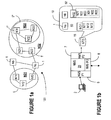
- FIG. 1a shows an example of a communication network 100, illustrating a possible hierarchical grouping of the network nodes.
- network 100 includes nodes 1 (Na) and 1' (Nb) and two node groups NG1, denoted with 5 and NG2, denoted with 5'.
- the nodes are grouped based on physical location or logical ordering, according to organizational rules used in the respective network.
- NG1 in this example includes nodes N11, N12 and N13.
- Nodes N21 and N22 are groups along with a node group NG3, denoted with 5", into node group NG2.
- NG3 contains nodes N31, N32 and N33.
- Figure 1b shows a data terminal (a workstation) 2, with the network management system NMS 20 which enables network operator access for transmitting commands to the NMS and receiving information about operation of the network.
- the NMS 20 has a user interface 6 which performs well known functions, and which has additional functionality according to the invention.
- a graphical user interface GUI on terminal 2 enables displaying various network maps on the screen of terminal 2, such as an entire network map, or parts of the network, at various granularities, as requested.
- Interface 6 verifies validity of any user request for a hierarchy altering operation of the network map 10, by verifying the correctness of the topology change data in the user request, as discussed later.
- NMS 20 maintains an updated view of the network it manages, as shown at 10 on Figure 1b , and a second interface 7 that enables changes to the map. That is, NMS 20 maintains a network topology database 15, which keeps the hierarchical information about the network node groups, nodes and network elements.
- An entire network map 10 shows only the managed objects at the top level of the hierarchy on network 100 of Figure 1a , i.e. nodes Na, Nb and groups NG1 and NG2. Maps for each group at the immediately next level are shown in coarse dotted lines under the respective node group, and maps at the next level are shown in fine dotted lines under the respective node group. Maps of finer granularity such as maps with the network elements at a certain node and their connectivity can also be viewed.
- the NMS 20 communicates with one or more element management systems EMS using a third interface 8.
- Interface 8 performs (in addition to the traditional mode of operation) new functions according to the invention.
- This NMS interface 8 identifies the EMS(s) affected by the user request for the respective hierarchy changing operation. Also, interface 8 transmits automatically a change request to the affected NMS for user changes to the portion of the map managed by the EMS, according to the topology change operation.
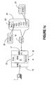
- Figure 1c shows a data terminal (a workstation) 3 with an element management system EMS 30.
- an EMS manages NE's of a similar type, and it may also maintain a topology database ETD 35 with hierarchical information about the subset of network elements in the sub-network it controls.
- EMS 30 may be provided with a user interface 16 for enabling communication with the network administrator using the GUI on terminal 3.
- this first EMS interface 16 also enables the EMS to receive a user request with topology change data pertaining to a specified network entity in the sub-network monitored and controlled by the respective EMS.
- interface 16 disables any subsequent user requests involving topology changes for the same network entity received on terminal 3, for enabling user request pertinent to said network entity from one localized place.
- Figure 1c shows a simplified scenario with one EMS managing all nodes of NG2.
- an EMS manages a subset of the network
- an NSM manages one or more EMS's.
- all nodes in NG1 are managed by the same EMS 30.
- Other scenarios may also be envisaged.
- one EMS could manage nodes N21 and N31, and a second EMS could manage nodes N22 and N33.
- N32 can be managed directly by the NMS 20.
- interface 8 of the NMS 20 shown in Figure 1b is responsible with identifying all affected EMS's due to user operation and then updating each accordingly.
- Network operators may also access the EMS database 35 to view a map 40 with the topology of the sub-network of interest on the GUI over a second EMS interface 17.
- a third EMS interface 18 enables communication with the NMS 20; pertinent to this invention is receiving from the NMS any change request affecting map 40, and transmitting automatically a user request for a hierarchy changing operation, if input from this EMS.
- EMS 30 manages the sub-network of node group 5', and that nodes N21 and N33 are access nodes.
- Access nodes are equipped with a subscriber access multiplexer (SAM) network element 25, which could be for example an ATM SAM (ASAM), used for enabling access to a plurality of users to communication network 100.
- SAM subscriber access multiplexer
- AAM ATM SAM
- map 40 of EMS 30 shows the SAM at nodes N21 and N33, while also providing the information that the node N33 is in node group 5".
- the workstation 3 with EMS 30 is also referred to as a SWS (SAM working station).
- EMS 30 is also equipped optionally with means for cyclically checking the state of the EMS. Thus, if a change request is received from the NMS and the EMS is temporarily in an 'off state', the change request is stored and the EMS status is cyclically checked. Once EMS 30 is back 'on', the change request is provided to the second EMS interface 17 and map 40 is altered accordingly.
- the NMS disseminates all network topology changes to the respective EMS's for keeping the network management system map 10 synchronized with the element management systems maps 40.
- the NMS 20 sends automatic change requests to the EMS's whenever a network topology change is made at the NMS.
- the EMS sends acknowledgements of the requests to the NMS.
- node group name changes are considered a change in the network topology, since these need also to be propagated to the EMS's.
- the above changes refer to node groups, nodes, and network elements. Automation of this process is particularly beneficial in the case of SAM nodes; a SWS may manage for example hundreds of subscriber access multiplexers, and manual updates are time-consuming, expensive and error-prone.
- any topological changes made on the EMS side such as addition of a SAM, is automatically propagated to the NMS.
- the EMS prevents the administrator from making any topological changes to that SAM.
- the NMS becomes responsible for any future changes, forcing the administrator to do the changes from one localized place.
- the invention provides more than just automating the EMS-NMS map synchronization.
- the challenging part of EMS-NMS map synchronization is for the NMS to verify that the request is valid for the EMS, before allowing the user to perform the change operation on the NMS map.
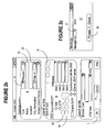
- Figure 2a shows an example of a network manager entire network map 10 as seen on the screen of workstation 2, illustrating nodes 1, 1' (e.g. Na and Nb for the example of Figure 1a ), and node groups NG1 and NG2.
- Scroll bars 21, 23 may be provided as well known to enable viewing of all entities at this level (entire network level).
- a control toolbar 27 with well-known pull down menus such as “File”, “Edit”, “View”, “Tools”, “Window, "Help” is also provided. Additional pull down menus “Create” shown at 22, and “List” shown at 24, are provided on toolbar 27 for enabling the operator to effect the topology changes on the NMS map.
- the "Create” button 22 will allow the user to add new equipment to the map, and the "List” button 24 allows the user to view all equipment matching a particular listing criteria.
- a map toolbar 24 with buttons 26 enables activating various commands on the respective map 10.
- Tool buttons allow the user to manipulate the view of the network map with operations such as Zoom In/Out, Change the selected object, View the color map and Traverse upwards the node group hierarchy.
- a field 45 may be provided for showing the hierarchical structure of the network 100, for enabling the user to select the display of the network entities at another level of interest.
- it could show nodes Na, Nb and node groups NG1 and NG2 at the entire network level.
- the nodes of node group NG1 i.e. nodes N11, N12 and N13
- the nodes of node group NG2 i.e. N21, N22 and NG3
- nodes N31, N32 and N33 may be viewed under node group NG3, etc.
- Figure 2b illustrates an example of the fields of the SAM workstation network element list (SNEL) used for creating a network element, and in particular a SAM 25.
- SNEL SAM workstation network element list
- the drawing illustrates one preferred embodiment, but other arrangements of the SNEL may also be envisaged.
- the EMS network element list is called ENEL.
- the SNEL includes in this example three main fields, namely field 4 with SAM information, field 6 with information pertaining to the OAM (operation administration and maintenance) interface at SAM, and field 8 with data on the OAM interface at element management layer (EML).
- EML element management layer
- Field 4 requires completion/selection of the SAM type 31, name 32, and location 33; information such as release may also be required for fully identifying the NE type.
- Filed 4 also requires completion of information regarding which component of the current EMS controls the newly created NE, such as EML workstation name, EML process, and access control domain (SWS name).
- the OAM interface at SAM field 6 enables assigning an address to the NE being created on the respective network.
- the IP address of the SAM should be specified at 34.
- the user can specify whether or not the SAM node once created will be supervised by the EMS or will be unsupervised (an unsupervised SAM node can later be supervised and vise versa). Support for protocols (such as BOOTP and SNTP) can be enabled/disabled in this part of the form.
- the SAM node is managed in a different subnet than the EMS and management messages need to go through another router, the user can specify the IP of that 38 router and the subnet mask 36 to be used.
- the OAM interface at EML field 8 requires specification/selection of the Ethernet or ATM host card.
- An "OK” button 7 is used to confirm completion of NE creation, while a “Cancel” button 9 enables corrections, and the "Help” button launches customer documentation for this form.
- Figure 2c illustrates a SAM creation form 41, entitled "New Node”.
- the administrator wishes to add a node to the NMS to manage, s/he selects an appropriate location of the node based on the existing node hierarchy and the organization rules used. The administrator then adds this new node at the respective hierarchical level (under a node group or at the entire network level) using map operations enabled on the NMS according to the invention. If an appropriate node group does not exist, the administrator can create it.
- SAM creation may be initialized from the NMS 20 with the group hierarchy information as a default value for the location name field 33.
- a user can create a SWS managed node by first issuing a "New Node” command under "Create” button 22 on the NMS map 10 (see Figure 2a ).
- the SWS element management system EMS 30 is selected in a "Managed By” field 37 on the form 41. Then, by clicking on the "Proceed” button 39 on the form 41, the SAM creation form shown in Figure 2b will have the "location” field 33 filed with the respective location information.
- field 33 is filed with "/" (root).
- NG3 is contained in NG2
- the user invokes the "New Node” command in the map for NG3
- the location field 33 on the SAM creation form in Figure 2b will be filled with "/Group2/Group3”.
- the EMS list of network elements will show the new location for node Na as "/NG2/NG3" instead of "/”. If then the user renames NG2 to NG5, the ENEL maintained by the affected EMS's will show the location name for Na as "/NG5/NG3". If the user then moves NG3 right under the "entire network”, the ENEL will show the location name as "/NG3". In essence, the location field will always contain the updates generated from the new group hierarchy on the NMS.
- the NMS also enables the operators to create the SAM node into an appropriate node group as a result of the modification of the SAM location from the SWS EMS.
- new groups are created automatically if they do not yet exist.
- the group in which the "create SAM" command was launched is used to create the default node location on the map of that EMS.
- the user may change the location if necessary. Once the user clicks on the "save" button 7.
- the new node location is sent by the EMS to the NMS, and the node is created in the appropriate group.
- the group hierarchy in which the SAM node is now located will be used to automatically generate the new location and be sent to the SWS EMS.
- the NMS becomes the master of the nodes location and the EMS 'freezes' the node location on the node configuration form.
- the only way to change this location is to use the NMS to move the SAM node to another group, or move or rename the node group in which the SAM node exists either directly or indirectly.
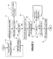
- FIG. 3 is a flowchart illustrating the method of synchronizing the NMS and EMS maps according to the invention.
- the operator performs a hierarchy altering operation on the NMS map, using the GUI.
- the change could be addition, upgrade, relocation or removal of a NE, a node, or a node group.
- a change may also be a node group name change or a node group relocation.
- the NMS 20 identifies the nodes affected by the operation, and determines the set of EMS's managing these nodes, denoted with EMSi as shown in step 51. It is to be understood that a change may affect more than one EMS, and as such the maps for each of the affected EMS needs to be updated.
- the NMS verifies the validity of the request with respect to each EMS, as shown in step 52 for EMSi.
- Request validity is verified before sending the request to the EMS's, against a set of rules and limitations 60.
- each EMS is specifically designed to manage a certain type of NEs, which may each have specific limitations. These limitations may include the allowable format of node names, a specified number of nodes allowed in an EMS span of control, the total length of the location identifier generated from the new SAM's location in the node group hierarchy, etc.
- the NMS will check first if the new group hierarchy does not contain any empty group names and that the resulting location identifier meets the other restrictions of that EMS.
- a NMS error message appears as a popup error window, and the respective operation is denied, step 54.
- the error messages may be as detailed as desired. For example, let us say that the user invokes the "New Node” command 26 from a group map with one of the parent groups in the hierarchy containing an empty name and sets the "Managed by" field 37 to SWS. After clicking on the "Proceed” button 39, the NMS will reject the node creation by displaying a popup window saying e.g. "Node creation failed. Enter a group name for one or more node groups to which the node belongs.”
- the empty name check is applied to all node groups in which the new node is being created (both direct and indirect containment) up to the entire network map.
- An "OK” button can also be provided on the popup error window, and when the user clicks on it, the popup window could disappear and "New Node" configuration window 41 could still be active.
- the check for an empty group name is also performed when renaming a group that contains SWS managed nodes. For example, the user may select to rename NG2. The new group's new name may be empty. However, the NMS will first check to see if an EMS managed SAM exists directly or indirectly in this node group. If it does, then an empty namewill not be allowed and a popup window will appear saying e.g.: "The group name cannot be empty. Please re-enter the group name”. As in the above example, the popup window has an "OK" button; when the user click on it, the popup window disappears and the original name of NG2 returns, to enable the operator to reselect a valid name. As shown in this example, the EMS enables restriction to naming of node groups, even though the name would have been valid from the perspective of the NMS.
- Example of invalid requests are syntax errors, such as resulting location identifier strings that are longer than permitted for the respective field on the EMS, or that contain characters that are considered invalid by the EMS. Invalid characters are treated in a similar manner.
- the NMS blocks creation of a node if one of the groups in the group hierarchy has characters "/" and " ⁇ ". In this case, these characters are considered valid from the NMS perspective as node group names, yet they are not valid from the EMS perspective; they cannot appear in the location field since these characters are reserved as separators.
- the user invokes the "New Node” command from the NSM and tries to create an SWS managed node in a group map, and that group or any of its parent groups has an invalid name from an EMS perspective, then clicking on the "Proceed” button 39 results in a popup window displaying an error message.
- the error message could in this case be: "Node creation failed.
- the group hierarchy for the node cannot contain one or more spaces or special characters (excluding dashes and underscores)."
- the window will disappear, as well as the "New Node” configuration window. The user will have to rename all of the non-conforming node groups before being able to successfully issue a SAM create request on the EMS from the NMS.
- the change relates to moving a SAM node, or if a node group that contains a SAM node is moved or renamed
- all node location rules for the EMS on the respective SWS need to be validated.
- the length of the new location name for each SAM node that resulted from a change as above should remain less than the maximum admissible number of characters, and must still contain no invalid characters.
- simply moving a node or a node group into another level of the network hierarchy would be invalid if the resulting node name string, which comprises the hierarchical location of the node after relocation, is too long.
- an option to disable these checks may also be provided. This will allow the user to decide when to enable the checks for maintaining consistency between the NMS node group hierarchy and the location attribute of the SAM's on the EMS's, and when to disable these.
- the user can resume the hierarchy altering operation, step 50 .
- the NMS changes the network map appropriately, step 55 , and the location field 33 is populated with the appropriate (new or modified) location, based on the node group hierarchy from the "entire network map" 10 .
- the change request is sent to the affected EMSi, as shown in step 56.
- EMSi For example, a user may wish to change the name of node group NG2 shown in Figure 1 a.
- the name change request is sent to EMS 30. It is to be understood that if more than one EMS is affected by a change request, the NMS sends change request messages to all affected EMS's.
- step 58 the EMS effects the change to its map, as discussed above in connection to Figures 2a-2c .
- the EMS sends acknowledgements of the requests to the NMS, step 61.
- step 57 Another issue to be considered in the verification step is updating the EMS in real time as the changes are being made.
- a delayed synchronization mechanism may also be provided optionally, with a view to handle the case when an EMS may be temporarily unreachable or too busy to make network map changes, as shown in dotted lines steps 57-59.
- the NMS checks in step 57 if the EMSi is operational. If yes, the change is readily implemented in the EMS map, step 58. If not, step 59, the request is stored and the NMS checks cyclically if EMSi is back.
- the NMS may not check the connection cyclically to the EMS, but provide the user with the ability to manually request an automatic resynchronization of the node group hierarchy of the NMS with the location attribute on the EMS.
- Such an operation may be applied to the entire network, to a particular SAM node, or to all SAM nodes in a subset of the hierarchy maintained by the NMS (e.g. selecting a node group and issuing that request).
Claims (21)
- Verfahren zur Synchronisierung einer Netzwerkverwaltungssystem- bzw.
NMS-Topologiekarte mit einer Elementverwaltungssystem- bzw. EMS-Topologiekarte in einem Kommunikationsnetzwerk mit einem NMS, welches eine NMS-Topologiekarte mit allen Netzwerkentitäten in dem besagten Kommunikationsnetzwerk und hierarchischen Informationen über den Standort der besagten Netzwerkentitäten pflegt, wobei das NMS ein oder mehrere EMSs verwaltet, wobei jedes EMS eine entsprechende EMS-Topologiekarte mit einem Teilsalz von Netzwerkentitäten und hierarchischen Informationen über den Standort der besagten Netzwerkentitäten in dem besagten Teilsatz pflegt, wobei das Verfahren dadurch gekennzeichnet ist, dass das Verfahren umfasst:Empfangen, an dem besagten NMS, einer Benutzeranforderung für einen Änderungsvorgang der besagten Hierarchie, wobei die Benutzeranforderung Topologieänderungsdaten enthält;Verifizieren der Gültigkeit der besagten Benutzeranforderung und, wenn die besagte Benutzerantwort gültig ist:Ändern der besagten NMS-Topologiekarte gemäß den besagten Topologieänderungsdaten in der besagten Benutzeranforderung;automatisches Senden, von dem besagten NMS an das besagte EMS, einer Änderungsanforderung mit den besagten Topologieänderungsdaten; undAktualisieren der besagten EMS-Topologiekarte gemäß der besagten Änderungsanforderung. - Verfahren nach Anspruch 1, weiterhin umfassend das Senden einer Bestätigung von dem besagten EMS an das besagte NMS, um das besagte NMS darüber zu informieren, dass die besagte EMS-Topologiekarte aktualisiert wurde.
- Verfahren nach Anspruch 1, wobei sich die besagten Topologieänderungsdaten auf das Hinzufügen, das Upgraden, das Versetzen, das Entfernen und/oder das Umbenennen einer Netzwerkentität beziehen.
- Verfahren nach Anspruch 3, wobei die besagte Netzwerkentität eine Knotengruppe, ein Netzwerkknoten und/oder ein Netzwerkelement ist.
- Verfahren nach Anspruch 1, weiterhin umfassend das Bereitstellen einer Fehlermeldung, wenn die besagte Benutzeranforderung ungültig ist.
- Verfahren nach Anspruch 1, wobei der besagte Schritt des Verifizierens der Gültigkeit der besagten Anforderung das Überprüfen der Syntax und der Vollständigkeit der besagten Benutzeranforderung umfasst.
- Verfahren nach Anspruch 1, wobei der besagte Schritt des Verifizierens das Überprüfen der Standort-Identifikationsdaten in der besagten Benutzeranforderung umfasst.
- Verfahren nach Anspruch 7, wobei die besagten Standort-Identifikationsdaten den hierarchischen Standort einer Netzwerkentität, zu welcher die besagten Topologieänderungsdaten gehören, liefern.
- Verfahren nach Anspruch 5, wobei die besagte Fehlermeldung angibt, dass die besagte Benutzeranforderung ungültige Zeichen enthält.
- Verfahren nach Anspruch 5, wobei die besagte Fehlermeldung angibt, dass die besagte Benutzeranforderung unzulässige Standort-Identifikationsdaten enthält.
- Verfahren nach Anspruch 10, wobei die besagten unzulässigen Standort-Identifikationsdaten einen unzulässigen Namen der Netzwerkentität, eine unzulässige Angabe der Hierarchie der Netzwerkentitäten und/oder einen fehlenden Namen für eine Netzwerkentität enthalten.
- Verfahren nach Anspruch 1, weiterhin umfassend das Identifizieren, an dem besagten NMS, des EMS, welches von der besagten Benutzeranforderung betroffen ist, um die Änderungsanforderung selektiv an das besagte betroffene EMS, welches eine oder mehrere betroffene Netzwerkentitäten verwaltet, zu senden.
- Verfahren nach Anspruch 1, weiterhin umfassend das zyklische Überprüfen des Zustands des besagten EMS, das Speichern der besagten Änderungsanforderung, wenn sich das besagte EMS vorübergehend in einem "außer Betrieb"-Zustand befindet, und das Bereitstellen der besagten Änderungsanforderung an das besagte EMS, wenn sich das besagte EMS wieder in einem "in Betrieb"-Zustand befindet.
- Verfahren zur Synchronisierung einer Netzwerkverwaltungssystem- bzw. NMS-Topologiekarte mit einer Elementverwaltungssystem- bzw. EMS-Topologiekarte in einem Kommunikationsnetzwerk mit einem NMS, welches eine NMS-Topologiekarte mit allen Netzwerkentitäten in dem besagten Kommunikationsnetzwerk und hierarchischen Informationen über den Standort der besagten Netzwerkentitäten pflegt und ein oder mehrere EMSs verwaltet, wobei jedes EMS eine entsprechende EMS-Topologiekarte mit einem Teilsatz von Netzwerkentitäten und hierarchischen Informationen über den Standort der besagten Netzwerkentitäten in dem besagten Teilsatz pflegt, wobei das Verfahren dadurch gekennzeichnet ist, dass das Verfahren umfasst:Empfangen, an dem besagten EMS, einer Benutzeranforderung für den Änderungsvorgang der besagten Hierarchie, wobei die Benutzeranforderung auf eine Netzwerkentität bezogene Topologieänderungsdaten enthält;automatisches Senden, von dem besagten EMS an das besagte NMS, einer Änderungsanforderung mit Topologieänderungsdaten;an dem besagten NMS, Verifizieren der Gültigkeit der besagten Benutzeranforderung; undÄndern der besagten NMS-Topologiekarte gemäß den besagten Topologieänderungsdaten in der besagten Benutzeranforderung, wenn die besagte Benutzeranforderung gültig ist.
- Verfahren nach Anspruch 14, wobei das besagte EMS alle folgenden Benutzeranforderungen, welche die besagten Topologieänderungsdaten von dem besagten EMS einbeziehen, sperrt, um Benutzeranforderungen, die sich auf die besagte Netzwerkentität beziehen, von einem lokalisierten Ort zu ermöglichen.
- Netzwerkverwaltungssystem, NMS, welches ein oder mehrere Elementverwaltungssysteme, EMS, verwaltet, wobei jedes EMS eine entsprechende EMS-Topologiekarte mit einem Teilsalz von Netzwerkentitäten und hierarchischen Informationen über den Standort der besagten Netzwerkentitäten in dem besagten Teilsalz pflegt, für ein Kommunikationsnetzwerk, umfassend:Eine NMS-Topologiekarte mit allen Netzwerkentitäten in dem besagten Kommunikationsnetzwerk und hierarchischen Informationen über den Standort der besagten Netzwerkentitäten;Mittel zum Ändern der besagten NMS-Topologiekarte,
dadurch gekennzeichnet, dass das besagte NMS weiterhin umfasst:Eine Benutzerschnittstelle zum Aktivieren des besagten NMS für den Empfang einer Benutzeranforderung mit auf eine spezifische Netzwerkentität bezogenen Topologieänderungsdaten;Mittel zum Verifizieren der Gültigkeit der besagten Benutzeranforderung;undMittel zum Erzeugen, ausgehend von der besagten Benutzeranforderung, einer Änderungsanforderung mit den besagten Topologieänderungsdaten, und zum automatischen Senden der besagten Änderungsanforderung an ein von der besagten Benutzeranforderung betroffenes EMS,wobei die besagten Mittel zum Ändern der besagten NMS-Topologiekarte fähig sind, die besagte NMS-Topologiekarte gemäß den besagten Topologieänderungsdaten zu ändern, wenn die besagte Benutzeranforderung gültig ist. - NMS nach Anspruch 16, wobei die besagten hierarchischen Informationen über den Standort der besagten Netzwerkentitäten einen Standort einer Netzwerkentität in dem gesamten Netzwerk, in einer Knotengruppe und/oder in einem Netzwerkknoten liefern.
- NMS nach Anspruch 16, wobei die besagte NMS-Topologiekarte in einer NMS-Datenbank gespeichert wird.
- NMS nach Anspruch 16, weiterhin umfassend Mittel zum Identifizieren des besagten von der besagten Benutzeranforderung betroffenen EMS.
- NMS nach Anspruch 16, wobei das besagte Mittel zum Verifizieren der Gültigkeit der besagten Benutzeranforderung einen Satz von EMS-spezifischen Regeln und Einschränkungen umfasst.
- NMS nach Anspruch 16, wobei das besagte Mittel zum Verifizieren eine Liste von Syntaxfehlern, ungültigen Zeichen und leeren Knotengruppennamen umfasst.
Applications Claiming Priority (1)
| Application Number | Priority Date | Filing Date | Title |
|---|---|---|---|
| US10/798,412 US7590072B2 (en) | 2004-03-12 | 2004-03-12 | Interworking network maps of network management and element management systems |
Publications (3)
| Publication Number | Publication Date |
|---|---|
| EP1655898A2 EP1655898A2 (de) | 2006-05-10 |
| EP1655898A3 EP1655898A3 (de) | 2011-03-02 |
| EP1655898B1 true EP1655898B1 (de) | 2013-06-05 |
Family
ID=34920266
Family Applications (1)
| Application Number | Title | Priority Date | Filing Date |
|---|---|---|---|
| EP05300177.2A Not-in-force EP1655898B1 (de) | 2004-03-12 | 2005-03-10 | Zusammenarbeitsnetzwerkpläne von einem Managementnetz und Elementmanagementsysteme |
Country Status (2)
| Country | Link |
|---|---|
| US (1) | US7590072B2 (de) |
| EP (1) | EP1655898B1 (de) |
Families Citing this family (40)
| Publication number | Priority date | Publication date | Assignee | Title |
|---|---|---|---|---|
| DE60129480T2 (de) * | 2001-12-31 | 2008-04-10 | Eci Telecom Ltd. | Technik zur bestimmung von konnektivitätslösungen für netzwerkelemente |
| US7280543B2 (en) * | 2002-08-23 | 2007-10-09 | Alcatel Canada Inc. | Extensible OAM support in MPLS/ATM networks |
| CN100349408C (zh) * | 2004-02-12 | 2007-11-14 | 华为技术有限公司 | 实现网管系统和网元设备配置数据实时同步的方法 |
| US7590072B2 (en) * | 2004-03-12 | 2009-09-15 | Alcatel Lucent | Interworking network maps of network management and element management systems |
| US20060026278A1 (en) * | 2004-07-27 | 2006-02-02 | Jian Yu | Administration system for network management systems |
| US7827215B2 (en) * | 2004-08-31 | 2010-11-02 | Alcatel-Lucent Usa Inc. | Real-time operation by a diskless client computer |
| US7986639B1 (en) * | 2004-10-26 | 2011-07-26 | Sprint Communications Company L.P. | Topology management of a communications network |
| US7542572B2 (en) * | 2004-12-01 | 2009-06-02 | Cisco Technology, Inc. | Method for securely and automatically configuring access points |
| EP1684218A1 (de) * | 2004-12-30 | 2006-07-26 | Sap Ag | System für das Modellieren eines Prozesses |
| US20070055597A1 (en) * | 2005-09-08 | 2007-03-08 | Visa U.S.A. | Method and system for manipulating purchase information |
| CN100382506C (zh) * | 2005-09-20 | 2008-04-16 | 华为技术有限公司 | 一种网络管理系统中对网元服务器进行认证的方法 |
| US8676931B1 (en) * | 2005-10-06 | 2014-03-18 | Hewlett-Packard Development Company, L.P. | Methods for managing manual changes to network infrastructures through automated systems |
| US9258327B2 (en) | 2006-04-27 | 2016-02-09 | Invention Science Fund I, Llc | Multi-network virus immunization |
| US8117654B2 (en) * | 2006-06-30 | 2012-02-14 | The Invention Science Fund I, Llc | Implementation of malware countermeasures in a network device |
| US8613095B2 (en) * | 2006-06-30 | 2013-12-17 | The Invention Science Fund I, Llc | Smart distribution of a malware countermeasure |
| US8966630B2 (en) * | 2006-04-27 | 2015-02-24 | The Invention Science Fund I, Llc | Generating and distributing a malware countermeasure |
| US8539581B2 (en) * | 2006-04-27 | 2013-09-17 | The Invention Science Fund I, Llc | Efficient distribution of a malware countermeasure |
| US20070268294A1 (en) * | 2006-05-16 | 2007-11-22 | Stephen Troy Eagen | Apparatus and method for topology navigation and change awareness |
| JP2008052524A (ja) * | 2006-08-25 | 2008-03-06 | Sony Corp | ネットワーク分析支援装置および方法、プログラム並びに記録媒体 |
| US7729287B2 (en) * | 2006-11-10 | 2010-06-01 | At&T Intellectual Property I, L.P. | Methods of providing simulation for communications systems and related systems and computer program products |
| KR101232371B1 (ko) * | 2006-12-01 | 2013-02-12 | 주식회사 케이티 | 데이터 대량 변경 처리 장치 및 방법 |
| US7945346B2 (en) * | 2006-12-14 | 2011-05-17 | Palo Alto Research Center Incorporated | Module identification method and system for path connectivity in modular systems |
| US8391487B2 (en) | 2007-07-24 | 2013-03-05 | Cisco Technology, Inc. | Secure remote configuration of device capabilities |
| US8000264B2 (en) * | 2009-04-29 | 2011-08-16 | Alcatel Lucent | Configuration management of IP/MPLS router rings |
| US20110022688A1 (en) * | 2009-07-27 | 2011-01-27 | Ahi Gvirtsman | Obtaining and displaying network topology information |
| US9400799B2 (en) * | 2010-10-04 | 2016-07-26 | Dell Products L.P. | Data block migration |
| IL213159A0 (en) * | 2011-05-26 | 2012-02-29 | Eci Telecom Ltd | Technique for management of communication networks |
| US9123003B2 (en) * | 2011-06-15 | 2015-09-01 | Hewlett-Packard Development Company, L.P. | Topologies corresponding to models for hierarchy of nodes |
| US20130283175A1 (en) * | 2012-04-23 | 2013-10-24 | Alcatel-Lucent Canada Inc. | Synchronization management groups |
| CN103078757B (zh) * | 2013-01-04 | 2016-06-15 | 中兴通讯股份有限公司 | 基于近场通信的网元设备管理方法及系统、巡检终端、网管及网元设备 |
| US11165624B2 (en) * | 2013-02-05 | 2021-11-02 | International Business Machines Corporation | Sentry for information technology system blueprints |
| CN104184602B (zh) * | 2013-05-23 | 2019-01-04 | 中兴通讯股份有限公司 | 增量数据同步方法、网元管理系统及网络管理系统 |
| CN105519041B (zh) * | 2013-09-28 | 2019-03-01 | 迈克菲股份有限公司 | 安全连接的框架 |
| CN105306331A (zh) * | 2014-07-24 | 2016-02-03 | 中兴通讯股份有限公司 | 一种发现拓扑网络的方法及网络设备 |
| US9585034B1 (en) * | 2015-06-25 | 2017-02-28 | Sprint Communications Company L.P. | Automated response system deactivation during large scale issues and managing wireless network operations |
| US10156842B2 (en) * | 2015-12-31 | 2018-12-18 | General Electric Company | Device enrollment in a cloud service using an authenticated application |
| US10056978B2 (en) | 2016-06-10 | 2018-08-21 | Tyco Electronics Subsea Communications Llc | Techniques for provisioning network elements of a data communications network (DCN) and an optical communication system using the same |
| US10680891B2 (en) * | 2018-02-28 | 2020-06-09 | Red Hat, Inc. | Networking visualizations that update data model and deploy visualization |
| JP2021119443A (ja) * | 2020-01-30 | 2021-08-12 | 富士フイルムビジネスイノベーション株式会社 | 情報処理装置及びコンピュータプログラム |
| US11799721B2 (en) * | 2022-01-27 | 2023-10-24 | Vmware, Inc. | Document driven network configuration updater |
Family Cites Families (27)
| Publication number | Priority date | Publication date | Assignee | Title |
|---|---|---|---|---|
| WO1992005485A2 (en) * | 1990-09-17 | 1992-04-02 | Cabletron Systems, Inc. | Network management system using model-based intelligence |
| US5758083A (en) * | 1995-10-30 | 1998-05-26 | Sun Microsystems, Inc. | Method and system for sharing information between network managers |
| US6335927B1 (en) * | 1996-11-18 | 2002-01-01 | Mci Communications Corporation | System and method for providing requested quality of service in a hybrid network |
| US6473408B1 (en) * | 1999-05-19 | 2002-10-29 | 3Com Corporation | Building a hierarchy in an asynchronous transfer mode PNNI network utilizing proxy SVCC-based RCC entities |
| JP2005512346A (ja) * | 1999-05-26 | 2005-04-28 | フジツウ ネットワーク コミュニケーションズ,インコーポレイテッド | ネットワーク要素管理システム |
| US6529938B1 (en) * | 1999-08-06 | 2003-03-04 | International Business Machines Corporation | Method, system, and program for executing operations on a client in a network environment |
| US6778517B1 (en) * | 1999-10-14 | 2004-08-17 | Bellsouth Intellectual Property Corporation | Wireless broadband service |
| US6564341B1 (en) * | 1999-11-19 | 2003-05-13 | Nortel Networks Limited | Carrier-grade SNMP interface for fault monitoring |
| US6721735B1 (en) * | 2000-03-13 | 2004-04-13 | Lucent Technologies Inc. | Method and apparatus for synchronizing databases in a network management system |
| US6836465B2 (en) * | 2001-11-29 | 2004-12-28 | Ipsum Networks, Inc. | Method and system for path identification in packet networks |
| US20020116485A1 (en) * | 2001-02-21 | 2002-08-22 | Equipe Communications Corporation | Out-of-band network management channels |
| WO2001091373A1 (fr) * | 2000-05-25 | 2001-11-29 | Fujitsu Limited | Procede de protection de repartiteurs, terminal de commande de reseau pour la mise en oeuvre dudit procede et dispositif de transmission |
| US6751660B1 (en) * | 2000-05-31 | 2004-06-15 | Cisco Technology, Inc. | Network management systems that receive cross connect and/or other circuit information from network elements |
| EP1185029B1 (de) * | 2000-09-01 | 2010-09-29 | International Business Machines Corporation | Dienst-Verteilung in Datennetzwerken |
| US7802287B2 (en) * | 2001-05-08 | 2010-09-21 | At&T Intellectual Property Ii, L.P. | Method and system for generating geographic visual displays of broadband network data |
| CA2405627A1 (en) * | 2001-09-28 | 2003-03-28 | Tyco Telecommunications (Us) Inc. | System and method of creating and maintaining a replicated naming service to support a telecommunications network |
| US20030101251A1 (en) * | 2001-11-27 | 2003-05-29 | Varros Telecom | Customizable element management system and method using element modeling and protocol adapters |
| US7305623B2 (en) * | 2001-12-03 | 2007-12-04 | Lucent Technologies Inc. | Method and apparatus for managing and representing elements in a network |
| US7092364B1 (en) * | 2001-12-28 | 2006-08-15 | Bellsouth Intellectual Property Corporation | System and method for monitoring DSL service provisioning |
| DE60129480T2 (de) * | 2001-12-31 | 2008-04-10 | Eci Telecom Ltd. | Technik zur bestimmung von konnektivitätslösungen für netzwerkelemente |
| US7188160B2 (en) * | 2002-01-22 | 2007-03-06 | Ericsson Ab | Method and apparatus for updating network device configuration information in a network management system |
| US20040030780A1 (en) * | 2002-08-08 | 2004-02-12 | International Business Machines Corporation | Automatic search responsive to an invalid request |
| US7191228B1 (en) * | 2002-09-30 | 2007-03-13 | Bellsouth Intellectual Property Corp. | Health checker for EMS CORBA notification listener |
| JP3913249B2 (ja) * | 2002-12-02 | 2007-05-09 | 富士通株式会社 | ネットワーク管理システムおよび該ネットワーク管理システムにより管理される伝送装置 |
| US8010643B2 (en) * | 2003-08-01 | 2011-08-30 | Opnet Technologies Inc | System and methods for simulating traffic generation |
| US20050108387A1 (en) * | 2003-10-31 | 2005-05-19 | Bingjun Li | System and apparatus for a network management system using presence and instant message techniques |
| US7590072B2 (en) * | 2004-03-12 | 2009-09-15 | Alcatel Lucent | Interworking network maps of network management and element management systems |
-
2004
- 2004-03-12 US US10/798,412 patent/US7590072B2/en not_active Expired - Fee Related
-
2005
- 2005-03-10 EP EP05300177.2A patent/EP1655898B1/de not_active Not-in-force
Also Published As
| Publication number | Publication date |
|---|---|
| US7590072B2 (en) | 2009-09-15 |
| EP1655898A2 (de) | 2006-05-10 |
| EP1655898A3 (de) | 2011-03-02 |
| US20050201299A1 (en) | 2005-09-15 |
Similar Documents
| Publication | Publication Date | Title |
|---|---|---|
| EP1655898B1 (de) | Zusammenarbeitsnetzwerkpläne von einem Managementnetz und Elementmanagementsysteme | |
| US7352853B1 (en) | Automation of customer premises equipment provisioning in a telecommunications network | |
| EP1427152B1 (de) | Verfahren zu automatischen Erkennung des virtuellen, lokalen Netzes | |
| JP3653660B2 (ja) | ネットワーク管理方法及びネットワーク管理システム | |
| US7185075B1 (en) | Element management system with dynamic database updates based on parsed snooping | |
| US20090222540A1 (en) | Architecture for operational support system | |
| EP1212686A1 (de) | Verwaltungs-system für netzwerk-elemente | |
| US7865576B2 (en) | Change of subscriber information in a multi-chassis network access environment | |
| EP1739877A1 (de) | Verfahren zur netzverwaltung | |
| EP1437861A2 (de) | Blockweise Servicekonfigurierung in Kommunikationsnetzwerken | |
| CN108023773A (zh) | 一种实现网络设备零配置上线的方法和配置服务器 | |
| US7729287B2 (en) | Methods of providing simulation for communications systems and related systems and computer program products | |
| CN102123040A (zh) | 数据配置的方法和装置 | |
| CN107733727A (zh) | 一种零配置方法、装置及设备 | |
| EP1479192B1 (de) | Verfahren und system zur verwaltung von konfiguration in einem netzwerk | |
| WO2022127535A1 (zh) | 动态消息管理装置、设备、系统、方法及存储介质 | |
| JP3903264B2 (ja) | ネットワーク管理方法及びネットワーク管理システム | |
| CN114567546A (zh) | 一种idc自动业务开通系统及使用方法 | |
| Cisco | Creating and Managing Clusters | |
| Cisco | Creating and Managing Clusters | |
| Cisco | Managing Clusters of Switches | |
| Cisco | Release Notes for CWSI UNIX Version 1.1 | |
| Cisco | Release Notes for CWSI UNIX Version 1.1 | |
| Cisco | Release Notes for CWSI UNIX Version 1.1 | |
| Cisco | Release Notes for CWSI UNIX Version 1.1 |
Legal Events
| Date | Code | Title | Description |
|---|---|---|---|
| PUAI | Public reference made under article 153(3) epc to a published international application that has entered the european phase |
Free format text: ORIGINAL CODE: 0009012 |
|
| AK | Designated contracting states |
Kind code of ref document: A2 Designated state(s): AT BE BG CH CY CZ DE DK EE ES FI FR GB GR HU IE IS IT LI LT LU MC NL PL PT RO SE SI SK TR |
|
| AX | Request for extension of the european patent |
Extension state: AL BA HR LV MK YU |
|
| RAP1 | Party data changed (applicant data changed or rights of an application transferred) |
Owner name: ALCATEL LUCENT |
|
| RIC1 | Information provided on ipc code assigned before grant |
Ipc: G06F 17/30 20060101ALI20100827BHEP Ipc: H04L 29/08 20060101ALI20100827BHEP Ipc: H04L 12/24 20060101ALI20100827BHEP Ipc: H04L 12/28 20060101AFI20060321BHEP |
|
| PUAL | Search report despatched |
Free format text: ORIGINAL CODE: 0009013 |
|
| AK | Designated contracting states |
Kind code of ref document: A3 Designated state(s): AT BE BG CH CY CZ DE DK EE ES FI FR GB GR HU IE IS IT LI LT LU MC NL PL PT RO SE SI SK TR |
|
| AX | Request for extension of the european patent |
Extension state: AL BA HR LV MK YU |
|
| RIC1 | Information provided on ipc code assigned before grant |
Ipc: H04L 12/56 20060101ALI20110124BHEP Ipc: H04L 29/08 20060101ALI20110124BHEP Ipc: H04L 12/24 20060101ALI20110124BHEP Ipc: G06F 17/30 20060101ALI20110124BHEP Ipc: H04L 12/28 20060101AFI20060321BHEP |
|
| 17P | Request for examination filed |
Effective date: 20110902 |
|
| AKX | Designation fees paid |
Designated state(s): AT BE BG CH CY CZ DE DK EE ES FI FR GB GR HU IE IS IT LI LT LU MC NL PL PT RO SE SI SK TR |
|
| RAP1 | Party data changed (applicant data changed or rights of an application transferred) |
Owner name: ALCATEL LUCENT |
|
| 17Q | First examination report despatched |
Effective date: 20120510 |
|
| GRAP | Despatch of communication of intention to grant a patent |
Free format text: ORIGINAL CODE: EPIDOSNIGR1 |
|
| GRAS | Grant fee paid |
Free format text: ORIGINAL CODE: EPIDOSNIGR3 |
|
| GRAA | (expected) grant |
Free format text: ORIGINAL CODE: 0009210 |
|
| AK | Designated contracting states |
Kind code of ref document: B1 Designated state(s): AT BE BG CH CY CZ DE DK EE ES FI FR GB GR HU IE IS IT LI LT LU MC NL PL PT RO SE SI SK TR |
|
| REG | Reference to a national code |
Ref country code: GB Ref legal event code: FG4D |
|
| RIC1 | Information provided on ipc code assigned before grant |
Ipc: G06F 17/30 20060101ALI20130426BHEP Ipc: H04L 12/70 20130101ALI20130426BHEP Ipc: H04L 29/08 20060101ALI20130426BHEP Ipc: H04L 12/24 20060101ALI20130426BHEP Ipc: H04L 12/28 20060101AFI20130426BHEP |
|
| REG | Reference to a national code |
Ref country code: CH Ref legal event code: EP |
|
| REG | Reference to a national code |
Ref country code: AT Ref legal event code: REF Ref document number: 616205 Country of ref document: AT Kind code of ref document: T Effective date: 20130615 |
|
| REG | Reference to a national code |
Ref country code: IE Ref legal event code: FG4D |
|
| REG | Reference to a national code |
Ref country code: DE Ref legal event code: R096 Ref document number: 602005039874 Country of ref document: DE Effective date: 20130801 |
|
| 111Z | Information provided on other rights and legal means of execution |
Free format text: AT BE BG CH CY CZ DE DK EE ES FI FR GB GR HU IE IS IT LI LT LU MC NL PL PT RO SE SI SK TR Effective date: 20130410 |
|
| REG | Reference to a national code |
Ref country code: AT Ref legal event code: MK05 Ref document number: 616205 Country of ref document: AT Kind code of ref document: T Effective date: 20130605 |
|
| PG25 | Lapsed in a contracting state [announced via postgrant information from national office to epo] |
Ref country code: SI Free format text: LAPSE BECAUSE OF FAILURE TO SUBMIT A TRANSLATION OF THE DESCRIPTION OR TO PAY THE FEE WITHIN THE PRESCRIBED TIME-LIMIT Effective date: 20130605 Ref country code: LT Free format text: LAPSE BECAUSE OF FAILURE TO SUBMIT A TRANSLATION OF THE DESCRIPTION OR TO PAY THE FEE WITHIN THE PRESCRIBED TIME-LIMIT Effective date: 20130605 Ref country code: ES Free format text: LAPSE BECAUSE OF FAILURE TO SUBMIT A TRANSLATION OF THE DESCRIPTION OR TO PAY THE FEE WITHIN THE PRESCRIBED TIME-LIMIT Effective date: 20130916 Ref country code: AT Free format text: LAPSE BECAUSE OF FAILURE TO SUBMIT A TRANSLATION OF THE DESCRIPTION OR TO PAY THE FEE WITHIN THE PRESCRIBED TIME-LIMIT Effective date: 20130605 Ref country code: FI Free format text: LAPSE BECAUSE OF FAILURE TO SUBMIT A TRANSLATION OF THE DESCRIPTION OR TO PAY THE FEE WITHIN THE PRESCRIBED TIME-LIMIT Effective date: 20130605 Ref country code: GR Free format text: LAPSE BECAUSE OF FAILURE TO SUBMIT A TRANSLATION OF THE DESCRIPTION OR TO PAY THE FEE WITHIN THE PRESCRIBED TIME-LIMIT Effective date: 20130906 Ref country code: SE Free format text: LAPSE BECAUSE OF FAILURE TO SUBMIT A TRANSLATION OF THE DESCRIPTION OR TO PAY THE FEE WITHIN THE PRESCRIBED TIME-LIMIT Effective date: 20130605 |
|
| REG | Reference to a national code |
Ref country code: NL Ref legal event code: VDEP Effective date: 20130605 |
|
| REG | Reference to a national code |
Ref country code: LT Ref legal event code: MG4D |
|
| PG25 | Lapsed in a contracting state [announced via postgrant information from national office to epo] |
Ref country code: BG Free format text: LAPSE BECAUSE OF FAILURE TO SUBMIT A TRANSLATION OF THE DESCRIPTION OR TO PAY THE FEE WITHIN THE PRESCRIBED TIME-LIMIT Effective date: 20130905 Ref country code: PL Free format text: LAPSE BECAUSE OF FAILURE TO SUBMIT A TRANSLATION OF THE DESCRIPTION OR TO PAY THE FEE WITHIN THE PRESCRIBED TIME-LIMIT Effective date: 20130605 |
|
| PG25 | Lapsed in a contracting state [announced via postgrant information from national office to epo] |
Ref country code: EE Free format text: LAPSE BECAUSE OF FAILURE TO SUBMIT A TRANSLATION OF THE DESCRIPTION OR TO PAY THE FEE WITHIN THE PRESCRIBED TIME-LIMIT Effective date: 20130605 Ref country code: IS Free format text: LAPSE BECAUSE OF FAILURE TO SUBMIT A TRANSLATION OF THE DESCRIPTION OR TO PAY THE FEE WITHIN THE PRESCRIBED TIME-LIMIT Effective date: 20131005 Ref country code: SK Free format text: LAPSE BECAUSE OF FAILURE TO SUBMIT A TRANSLATION OF THE DESCRIPTION OR TO PAY THE FEE WITHIN THE PRESCRIBED TIME-LIMIT Effective date: 20130605 Ref country code: BE Free format text: LAPSE BECAUSE OF FAILURE TO SUBMIT A TRANSLATION OF THE DESCRIPTION OR TO PAY THE FEE WITHIN THE PRESCRIBED TIME-LIMIT Effective date: 20130605 Ref country code: PT Free format text: LAPSE BECAUSE OF FAILURE TO SUBMIT A TRANSLATION OF THE DESCRIPTION OR TO PAY THE FEE WITHIN THE PRESCRIBED TIME-LIMIT Effective date: 20131007 Ref country code: CZ Free format text: LAPSE BECAUSE OF FAILURE TO SUBMIT A TRANSLATION OF THE DESCRIPTION OR TO PAY THE FEE WITHIN THE PRESCRIBED TIME-LIMIT Effective date: 20130605 |
|
| PG25 | Lapsed in a contracting state [announced via postgrant information from national office to epo] |
Ref country code: NL Free format text: LAPSE BECAUSE OF FAILURE TO SUBMIT A TRANSLATION OF THE DESCRIPTION OR TO PAY THE FEE WITHIN THE PRESCRIBED TIME-LIMIT Effective date: 20130605 Ref country code: RO Free format text: LAPSE BECAUSE OF FAILURE TO SUBMIT A TRANSLATION OF THE DESCRIPTION OR TO PAY THE FEE WITHIN THE PRESCRIBED TIME-LIMIT Effective date: 20130605 |
|
| PLBE | No opposition filed within time limit |
Free format text: ORIGINAL CODE: 0009261 |
|
| STAA | Information on the status of an ep patent application or granted ep patent |
Free format text: STATUS: NO OPPOSITION FILED WITHIN TIME LIMIT |
|
| PG25 | Lapsed in a contracting state [announced via postgrant information from national office to epo] |
Ref country code: DK Free format text: LAPSE BECAUSE OF FAILURE TO SUBMIT A TRANSLATION OF THE DESCRIPTION OR TO PAY THE FEE WITHIN THE PRESCRIBED TIME-LIMIT Effective date: 20130605 |
|
| 26N | No opposition filed |
Effective date: 20140306 |
|
| PG25 | Lapsed in a contracting state [announced via postgrant information from national office to epo] |
Ref country code: IT Free format text: LAPSE BECAUSE OF FAILURE TO SUBMIT A TRANSLATION OF THE DESCRIPTION OR TO PAY THE FEE WITHIN THE PRESCRIBED TIME-LIMIT Effective date: 20130605 |
|
| REG | Reference to a national code |
Ref country code: DE Ref legal event code: R097 Ref document number: 602005039874 Country of ref document: DE Effective date: 20140306 |
|
| REG | Reference to a national code |
Ref country code: CH Ref legal event code: PCOW Free format text: NEW ADDRESS: 148/152 ROUTE DE LA REINE, 92100 BOULOGNE-BILLANCOURT (FR) |
|
| PG25 | Lapsed in a contracting state [announced via postgrant information from national office to epo] |
Ref country code: LU Free format text: LAPSE BECAUSE OF FAILURE TO SUBMIT A TRANSLATION OF THE DESCRIPTION OR TO PAY THE FEE WITHIN THE PRESCRIBED TIME-LIMIT Effective date: 20140310 |
|
| REG | Reference to a national code |
Ref country code: CH Ref legal event code: PL |
|
| REG | Reference to a national code |
Ref country code: IE Ref legal event code: MM4A |
|
| PG25 | Lapsed in a contracting state [announced via postgrant information from national office to epo] |
Ref country code: LI Free format text: LAPSE BECAUSE OF NON-PAYMENT OF DUE FEES Effective date: 20140331 Ref country code: CH Free format text: LAPSE BECAUSE OF NON-PAYMENT OF DUE FEES Effective date: 20140331 Ref country code: IE Free format text: LAPSE BECAUSE OF NON-PAYMENT OF DUE FEES Effective date: 20140310 |
|
| REG | Reference to a national code |
Ref country code: FR Ref legal event code: PLFP Year of fee payment: 11 |
|
| REG | Reference to a national code |
Ref country code: FR Ref legal event code: PLFP Year of fee payment: 12 |
|
| PG25 | Lapsed in a contracting state [announced via postgrant information from national office to epo] |
Ref country code: MC Free format text: LAPSE BECAUSE OF FAILURE TO SUBMIT A TRANSLATION OF THE DESCRIPTION OR TO PAY THE FEE WITHIN THE PRESCRIBED TIME-LIMIT Effective date: 20130605 |
|
| PGFP | Annual fee paid to national office [announced via postgrant information from national office to epo] |
Ref country code: FR Payment date: 20160321 Year of fee payment: 12 Ref country code: GB Payment date: 20160321 Year of fee payment: 12 |
|
| PG25 | Lapsed in a contracting state [announced via postgrant information from national office to epo] |
Ref country code: CY Free format text: LAPSE BECAUSE OF FAILURE TO SUBMIT A TRANSLATION OF THE DESCRIPTION OR TO PAY THE FEE WITHIN THE PRESCRIBED TIME-LIMIT Effective date: 20130605 |
|
| PG25 | Lapsed in a contracting state [announced via postgrant information from national office to epo] |
Ref country code: TR Free format text: LAPSE BECAUSE OF FAILURE TO SUBMIT A TRANSLATION OF THE DESCRIPTION OR TO PAY THE FEE WITHIN THE PRESCRIBED TIME-LIMIT Effective date: 20130605 Ref country code: HU Free format text: LAPSE BECAUSE OF FAILURE TO SUBMIT A TRANSLATION OF THE DESCRIPTION OR TO PAY THE FEE WITHIN THE PRESCRIBED TIME-LIMIT; INVALID AB INITIO Effective date: 20050310 |
|
| PGFP | Annual fee paid to national office [announced via postgrant information from national office to epo] |
Ref country code: DE Payment date: 20160330 Year of fee payment: 12 |
|
| REG | Reference to a national code |
Ref country code: DE Ref legal event code: R119 Ref document number: 602005039874 Country of ref document: DE |
|
| GBPC | Gb: european patent ceased through non-payment of renewal fee |
Effective date: 20170310 |
|
| REG | Reference to a national code |
Ref country code: FR Ref legal event code: ST Effective date: 20171130 |
|
| PG25 | Lapsed in a contracting state [announced via postgrant information from national office to epo] |
Ref country code: DE Free format text: LAPSE BECAUSE OF NON-PAYMENT OF DUE FEES Effective date: 20171003 Ref country code: FR Free format text: LAPSE BECAUSE OF NON-PAYMENT OF DUE FEES Effective date: 20170331 |
|
| PG25 | Lapsed in a contracting state [announced via postgrant information from national office to epo] |
Ref country code: GB Free format text: LAPSE BECAUSE OF NON-PAYMENT OF DUE FEES Effective date: 20170310 |