EP1655613A2 - Low power and proximity AC current sensor - Google Patents
Low power and proximity AC current sensor Download PDFInfo
- Publication number
- EP1655613A2 EP1655613A2 EP05024218A EP05024218A EP1655613A2 EP 1655613 A2 EP1655613 A2 EP 1655613A2 EP 05024218 A EP05024218 A EP 05024218A EP 05024218 A EP05024218 A EP 05024218A EP 1655613 A2 EP1655613 A2 EP 1655613A2
- Authority
- EP
- European Patent Office
- Prior art keywords
- current sensor
- low
- set forth
- power proximity
- magnetic material
- Prior art date
- Legal status (The legal status is an assumption and is not a legal conclusion. Google has not performed a legal analysis and makes no representation as to the accuracy of the status listed.)
- Withdrawn
Links
Images






Classifications
-
- G—PHYSICS
- G01—MEASURING; TESTING
- G01R—MEASURING ELECTRIC VARIABLES; MEASURING MAGNETIC VARIABLES
- G01R15/00—Details of measuring arrangements of the types provided for in groups G01R17/00 - G01R29/00, G01R33/00 - G01R33/26 or G01R35/00
- G01R15/14—Adaptations providing voltage or current isolation, e.g. for high-voltage or high-current networks
- G01R15/146—Measuring arrangements for current not covered by other subgroups of G01R15/14, e.g. using current dividers, shunts, or measuring a voltage drop
- G01R15/148—Measuring arrangements for current not covered by other subgroups of G01R15/14, e.g. using current dividers, shunts, or measuring a voltage drop involving the measuring of a magnetic field or electric field
Definitions
- FIG. 1 is a schematic diagram illustrating the construction of a typical ampere meter and the arrangement of the components thereof.
- the ampere meter is generally connected in series to a conducting line through which current flows, and measures the amount of current in the conducting line using the electromagnetic force that is generated between a magnetic field generated by current flowing through a movable coil wound on a soft iron core, and a permanent magnet mounted in the ampere meter.
- the ampere meter-type current sensors are difficult to install because they are directly connected to conducting lines through which current flows, and are disadvantageous in that they have many movable components and are large, thus being expensive.
- the hall sensors and the GMR-type current sensors have advantages in size and ease of installation over the ampere meter-type current sensors, but are disadvantageous in that power is consumed because power is supplied to the sensors and the sensors are operated using the power. These types of sensors are unsuitable for use in sensor networks because of their size, price and power consumption.
- the present invention provides a low-power proximity AC current sensor, including a magnetic material having a location that changes depending on the intensity of a magnetic field formed outside the magnetic material; a piezoelectric film disposed at a location adjacent to the magnetic material and configured to generate electric charge due to a change in location of the magnetic material; and a substrate for securing the piezoelectric film.
- the present invention uses a method of detecting a piezoelectric effect varying depending on current and a method of detecting variation in capacitance. Furthermore, the present invention provides a low-power proximity AC current sensor that can detect the amount of current only by causing the sensor to approach a conducting line through which the current flows, without an electrical connection, unlike an existing current sensor that is connected to the interior of an electrical circuit formed by a conducting line for which the amount of current is detected.
- the low-power proximity AC current sensor basically includes a cantilever, a bridge, a membrane movable structure, and a magnetic material and a sensing part provided in the movable structure.
- the magnetic material of the proximity current sensor according to the present invention is subjected to force due to an induced magnetic field generated by AC current around the conducting line, therefore the movable structure is moved, thus resulting in the deformation and displacement thereof. Such deformation or displacement is detected using a piezoelectric effect or variation in capacitance.
- FIG. 2 is a perspective view of a low-power proximity AC current sensor 20 according to an embodiment of the present invention.
- the low-power proximity AC current sensor 20 includes a magnetic material 21, a piezoelectric thin film 22, an upper plate wire 23, a lower plate wire 24 and a substrate 25.
- FIG. 2 a structure in which the low power AC current sensor 20 is formed of the piezoelectric film 22 is schematically illustrated.
- a depression 26 is formed in the substrate 25 at a location that is slightly biased from the center thereof to one side.
- the piezoelectric film 22 is formed over the depression 26.
- the location of the depression 26 is not limited to the one described above, but can be any location on the substrate 25 as long as the piezoelectric film 22 is allowed to move freely.
- the magnetic material 21 is layered on the piezoelectric film 22.
- a pair of electrode wires 23 and 24 is formed at one side of the piezoelectric film 22.
- the upper plate wire 23 is brought into contact with the upper surface of the piezoelectric film 22, while the lower plate wire 24 is connected to the lower surface of the piezoelectric film 22.
- the piezoelectric film 22 has a cantilever shape.
- the piezoelectric film 22 may have various shapes. A method of forming the piezoelectric film 22 will be described in detail below with reference to FIG. 3.
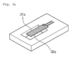
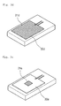
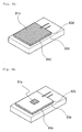
- FIGS. 3A to 3F show various examples of a low-power proximity AC current sensor according to embodiments of the present invention.
- FIG. 3A shows a cantilever-shaped low-power proximity AC current sensor in which a magnetic material 31a is deposited on the entire surface of a piezoelectric film 32b.
- FIG. 3B shows a bridge-shaped low-power proximity AC current sensor in which a magnetic material 31b is deposited on part of a piezoelectric film 32b.
- FIG. 3C shows a bridge-shaped low-power proximity AC current sensor in which a magnetic material 31c is deposited on the entire surface of a piezoelectric film 32c.
- FIG. 3D shows a thin film-type low-power proximity AC current sensor in which a magnetic material 31d is deposited on the entire surface of a piezoelectric film 32d.
- a concentric circle-shaped magnetic field is generated around a conducting line 41 due to current flowing through the conducting line 41.
- the low-power current sensor 20, including a piezoelectric film to which a magnetic material is attached is moved by the magnetic field.
- an electric charge is generated by the movement of the piezoelectric film, the voltage or current of which can be measured.
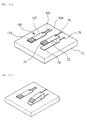
- FIGS. 6A and 6B are perspective views of a low-power proximity AC current sensor package having an additional external noise removal function according to an embodiment of the present invention.
- a reference sensor 61 is further included in the low-power proximity AC current sensor 20 shown in FIG. 2.
- FIGS. 6A and 6B the shape of the reference sensor 61 is schematically illustrated.
- the reference sensor 61 has the same construction as the current sensor shown in FIG. 2 except that a depression is not formed in the portion of a substrate 25 where the reference sensor 61 is formed.
- noise components as well as a signal generated from current always exist around a conducting line through which the current flows.
- the reference sensor 61 may additionally be used.
- the reference sensor 61 generates only noise components in which the movement of a corresponding electrode is not included. Therefore, when the two signals are subtracted from each other, a pure signal generated by the current can be detected.
- the low-power proximity AC current sensor includes a magnetic material 71, corresponding electrodes 72 and 73, a support 74, electrode wires 75 and 76, and a substrate 77.
- FIG. 7 a structure in which the corresponding electrodes 72 and 73 are formed on the substrate 77 is schematically illustrated.
- the corresponding electrodes 72 and 73 are formed on the top of the substrate 77.
- the magnetic material 71 is layered on the top of the corresponding electrodes 72.
- the corresponding electrodes 72 and 73 are formed such that the upper plate 72 and the lower plate 73 face each other and have a predetermined gap therebetween. It is preferred that the predetermined gap between the upper plate 72 and the lower plate 73 be achieved by layering the support 74 having a predetermined thickness on one side of the lower plate 73 and layering the upper plate 72 on the support 74.
- the electrode wires 75 and 76 are brought into contact with first sides of the upper plate 72 and the lower plate 73 that are in contact with the support 74. It is preferred that the upper plate wire 75 be connected to the upper surface of a first side of the upper plate 72 and the lower plate wire 76 be connected to the lower surface of a first side of the lower plate 73.
- the current sensor may be formed in a cantilever shape.
- the corresponding electrodes 72 and 73 may be formed in various shapes. A method of forming corresponding electrodes will be described in detail below with reference to FIG. 8.
- the upper plate 72 is deformed by the movement of the magnetic material 71.
- the magnetic material 71 formed on the upper plate 72 is moved by a magnetic field formed around the upper plate 72, the upper plate 72 is deformed.
- the location of the magnetic material 71 changes in proportion to the magnitude of a surrounding magnetic field.
- the distance between the upper plate 72 and the lower plate 73 varies. This variation changes the capacitance between the two electrodes 72 and 73. Therefore, the capacitance changes in proportion to the amount of the magnetic field formed around the conducting line, so that the magnitude of a magnetic field can be easily measured.
- FIGS. 8A to 8F show various examples of a capacitance detection-type low-power proximity AC current sensor according to an embodiment of the present invention.
- FIG. 8A shows a cantilever-shaped capacitance detection-type low-power proximity AC current sensor in which a magnetic material 81a is formed on the entire upper surface of an upper plate 82a.
- the structure of this embodiment is almost the same as that shown in FIG. 7.
- the magnetic material provided in the capacitance detection-type low-power proximity AC current sensor shown in FIG. 7 is layered on part of the upper plate, whereas the magnetic material in this embodiment is layered on the entire surface of the upper plate 82a.
- the sensor has a support 83a disposed between the first sides of the corresponding electrodes 82a and 84a, thus forming a gap.
- FIG. 8B shows a capacitance detection-type low-power proximity AC current sensor in which a magnetic material 81b is formed on part of an upper plate 82b.
- the structure of this embodiment is the same as that shown in FIG. 7 except that the magnetic material 81b is layered at the center of the upper plate 82b, but not on one side of the upper plate 82b.
- supports 83b are formed not only on first sides of the corresponding electrodes 82a and 84a but also on second sides thereof. Therefore, a gap is formed between the upper and lower plates 82b and 84b by the supports 83b.
- the distance between the central portions of the corresponding electrodes 82b and 84b varies depending on variation in an external magnetic field, thus resulting in variation in capacitance.
- FIG. 8C shows a capacitance detection-type low-power proximity AC current sensor in which a magnetic material 81c is formed on the entire surface of the upper plate 82c of the current sensor.
- the structure of the present embodiment is the same as that of FIG. 8B except that the magnetic material 81c is formed on the entire surface of the upper plate 82c.
- the sensor also has supports 83c formed on both sides of corresponding electrodes 82c and 84c.
- FIG. 8E shows a thin film-shaped capacitance detection-type low-power proximity AC current sensor in which a magnetic material is formed on part of the upper surface of a corresponding electrode.
- the structure of the present embodiment is almost the same as that of FIG. 8d except that a magnetic material 81e layered on the upper surface of an upper plate 82e is formed at the center portion of the current sensor.
- FIG. 8F is a sectional view of the low-power proximity sensor shown in FIG. 8E.
- a gap is also formed between corresponding electrodes 82e and 84e.
- FIGS. 9 and 10 show a state where the capacitance detection-type low-power proximity AC current sensor 70 according to the embodiment of the present invention is attached to a conducting line 90.
- FIGS. 11A and 11B are perspective views of a capacitance detection-type low-power proximity AC current sensor having an external noise removal function according to an embodiment of the present invention.
- the low-power proximity current sensor of the present invention which can be fabricated using micro-machine technology and a semiconductor process, can be integrated with a semiconductor circuit, thus implementing an integrated micro-miniature proximity current sensor.
- the AC current sensor employs a method of detecting variation in capacitance, so that the AC current sensor has low power consumption and can be used for applications that require low power and micro-sized sensors, such as a sensor network.
Landscapes
- Physics & Mathematics (AREA)
- General Physics & Mathematics (AREA)
- Measuring Magnetic Variables (AREA)
- Measuring Instrument Details And Bridges, And Automatic Balancing Devices (AREA)
Abstract
Description
- The document relates to a low-power proximity Alternating Current (AC) current sensor.
- In general, AC current sensors are classified into ampere meter-type sensors that detect current using electromagnetic force generated between current flowing through a coil and a magnet, hall sensors that use the Hall effect, and Great Magneto-Resistance (GMR)-type current sensors that detect variation in magneto-resistance.
- FIG. 1 is a schematic diagram illustrating the construction of a typical ampere meter and the arrangement of the components thereof. The ampere meter is generally connected in series to a conducting line through which current flows, and measures the amount of current in the conducting line using the electromagnetic force that is generated between a magnetic field generated by current flowing through a movable coil wound on a soft iron core, and a permanent magnet mounted in the ampere meter.
- However, the ampere meter-type current sensors are difficult to install because they are directly connected to conducting lines through which current flows, and are disadvantageous in that they have many movable components and are large, thus being expensive. Meanwhile, the hall sensors and the GMR-type current sensors have advantages in size and ease of installation over the ampere meter-type current sensors, but are disadvantageous in that power is consumed because power is supplied to the sensors and the sensors are operated using the power. These types of sensors are unsuitable for use in sensor networks because of their size, price and power consumption.
- Accordingly, the present invention has been made keeping in mind the above problems occurring in the prior art, and an object of the present invention is to provide a low-power proximity AC current sensor that measures the amount of AC current flowing through a conducting line using electromagnetic force that is applied to a magnetic material, which is attached to the sensor, by a magnetic field induced by the current flowing through the conducting line.
- In order to accomplish the above object, the present invention provides a low-power proximity AC current sensor, including a magnetic material having a location that changes depending on the intensity of a magnetic field formed outside the magnetic material; a piezoelectric film disposed at a location adjacent to the magnetic material and configured to generate electric charge due to a change in location of the magnetic material; and a substrate for securing the piezoelectric film.
- Furthermore, the present invention provides a low-power proximity AC current sensor, including a magnetic material having a location that changes depending on the intensity of a magnetic field formed outside the magnetic material; corresponding electrodes disposed at a location adjacent to the magnetic material and configured to vary capacitance depending on a change in location of the magnetic material; and a substrate for securing the piezoelectric film.
- In order to implement a low-power sensor, the present invention uses a method of detecting a piezoelectric effect varying depending on current and a method of detecting variation in capacitance. Furthermore, the present invention provides a low-power proximity AC current sensor that can detect the amount of current only by causing the sensor to approach a conducting line through which the current flows, without an electrical connection, unlike an existing current sensor that is connected to the interior of an electrical circuit formed by a conducting line for which the amount of current is detected.
- The low-power proximity AC current sensor according to the present invention basically includes a cantilever, a bridge, a membrane movable structure, and a magnetic material and a sensing part provided in the movable structure. The magnetic material of the proximity current sensor according to the present invention is subjected to force due to an induced magnetic field generated by AC current around the conducting line, therefore the movable structure is moved, thus resulting in the deformation and displacement thereof. Such deformation or displacement is detected using a piezoelectric effect or variation in capacitance.
- In particular, the AC current sensor according to the present invention can detect current only by being attached to a predetermined location, such as a covering part, that is adjacent to the conducting line through which the AC current flows. Since the piezoelectric effect and variation in capacitance are generated due to the movement of the movable structure, power consumption can be considerably reduced.
- The above and other objects, features and advantages of the present invention will be more clearly understood from the following detailed description taken in conjunction with the accompanying drawings, in which:
- FIG. 1 is a perspective view illustrating the internal structure of a typical ampere meter;
- FIG. 2 is a perspective view of a low-power proximity AC current sensor according to an embodiment of the present invention;
- FIGS. 3A to 3F are perspective views showing various examples of low-power proximity AC current sensors according to embodiments of the present invention;
- FIG. 4 is a perspective view showing an example of the mounting of the low-power proximity AC current sensor according to the embodiment of the present invention;
- FIG. 5 is a conceptual view illustrating the operational principle of the low-power proximity AC current sensor according to the embodiment of the present invention;
- FIGS. 6A and 6B are perspective views of a low-power proximity AC current sensor having an additional external noise removal function according to an embodiment of the present invention;
- FIG. 7 is a perspective view of a capacitance detection-type low-power proximity AC current sensor according to an embodiment of the present invention;
- FIGS. 8A to 8F show various examples of the capacitance detection-type low-power proximity AC current sensor according to an embodiment of the present invention;
- FIG. 9 shows an example the mounting of the capacitance detection-type low-power proximity AC current sensor according to the embodiment of the present invention;
- FIG. 10 is a conceptual view illustrating the operating principle of the capacitance detection-type low-power proximity AC current sensor according to an embodiment of the present invention; and
- FIGS. 11A and 11B are perspective views of a capacitance detection-type low-power proximity AC current sensor having an external noise removal function according to an embodiment of the present invention.
- Preferred embodiments of the present invention will be described in detail below with reference to the accompanying drawings. Reference now should be made to the drawings, in which the same reference numerals are used throughout the different drawings to designate the same or similar components.
- FIG. 2 is a perspective view of a low-power proximity AC
current sensor 20 according to an embodiment of the present invention. - In this embodiment, the low-power proximity AC
current sensor 20 includes amagnetic material 21, a piezoelectricthin film 22, anupper plate wire 23, alower plate wire 24 and asubstrate 25. - In FIG. 2, a structure in which the low power AC
current sensor 20 is formed of thepiezoelectric film 22 is schematically illustrated. - Referring to FIG. 2, a
depression 26 is formed in thesubstrate 25 at a location that is slightly biased from the center thereof to one side. Thepiezoelectric film 22 is formed over thedepression 26. The location of thedepression 26 is not limited to the one described above, but can be any location on thesubstrate 25 as long as thepiezoelectric film 22 is allowed to move freely. - The
magnetic material 21 is layered on thepiezoelectric film 22. A pair ofelectrode wires piezoelectric film 22. Theupper plate wire 23 is brought into contact with the upper surface of thepiezoelectric film 22, while thelower plate wire 24 is connected to the lower surface of thepiezoelectric film 22. In the above-described embodiment, thepiezoelectric film 22 has a cantilever shape. Thepiezoelectric film 22 may have various shapes. A method of forming thepiezoelectric film 22 will be described in detail below with reference to FIG. 3. - The
piezoelectric film 22 generates electric charge by the deformation thereof. It is preferred that Rochelle salt or barium titanate, having a high piezoelectric effect, be used as the material of thepiezoelectric film 22. - The
piezoelectric film 22 is deformed by the movement of themagnetic material 21. If a magnetic field is formed around thepiezoelectric film 22 and themagnetic material 21 formed on thepiezoelectric film 22 moves, thepiezoelectric film 22 is deformed accordingly. The change in location of the magnetic material is proportional to the magnitude of the surrounding magnetic field. - The
electrode wires piezoelectric film 22, to a predetermined measuring device (not shown) in order to measure the amount of charge generated in thepiezoelectric film 22. - In summary, when AC current is formed in a typical conducting line, a magnetic field is formed around the conducting line in proportion to the amount of current, the location of the
magnetic material 21 changes in proportion to the magnitude of the magnetic field, and the amount of electric charge formed in thepiezoelectric film 22 changes depending on the change in location of themagnetic material 21, so that the amount of current can be measured. - FIGS. 3A to 3F show various examples of a low-power proximity AC current sensor according to embodiments of the present invention.
- FIG. 3A shows a cantilever-shaped low-power proximity AC current sensor in which a
magnetic material 31a is deposited on the entire surface of apiezoelectric film 32b. FIG. 3B shows a bridge-shaped low-power proximity AC current sensor in which amagnetic material 31b is deposited on part of apiezoelectric film 32b. FIG. 3C shows a bridge-shaped low-power proximity AC current sensor in which amagnetic material 31c is deposited on the entire surface of apiezoelectric film 32c. FIG. 3D shows a thin film-type low-power proximity AC current sensor in which amagnetic material 31d is deposited on the entire surface of apiezoelectric film 32d. FIG. 3E shows a thin film-type low-power proximity AC current sensor in which amagnetic material 31e is deposited on part of apiezoelectric film 32e. FIG. 3F shows an AC sensor from which the magnetic material of the thin film type AC sensor shown in FIG. 3D or 3E is removed. It is preferred that adepression 32f formed in the substrate of the AC sensor having the thin film shape be larger than those formed in the AC sensors having the cantilever and bridge shapes. - FIG. 4 shows an example of the mounting of the low-power proximity AC current sensor according to the embodiment of the present invention. FIG. 5 is a conceptual view illustrating the operational principle of a low-power proximity AC
current sensor 20 according to the embodiment of the present invention. - Referring to FIG. 5, a concentric circle-shaped magnetic field is generated around a conducting
line 41 due to current flowing through the conductingline 41. The low-power current sensor 20, including a piezoelectric film to which a magnetic material is attached, is moved by the magnetic field. As shown in FIG. 5, in the case of the piezoelectric film made of a piezoelectric material, an electric charge is generated by the movement of the piezoelectric film, the voltage or current of which can be measured. - FIGS. 6A and 6B are perspective views of a low-power proximity AC current sensor package having an additional external noise removal function according to an embodiment of the present invention.
- In this embodiment, in the low-power proximity AC current sensor package, a
reference sensor 61 is further included in the low-power proximity ACcurrent sensor 20 shown in FIG. 2. - In FIGS. 6A and 6B, the shape of the
reference sensor 61 is schematically illustrated. - Referring to FIG. 6A, the
reference sensor 61 has the same construction as the current sensor shown in FIG. 2 except that a depression is not formed in the portion of asubstrate 25 where thereference sensor 61 is formed. In general, noise components as well as a signal generated from current always exist around a conducting line through which the current flows. In order to remove the external noise components, thereference sensor 61 may additionally be used. For the same current input, thereference sensor 61 generates only noise components in which the movement of a corresponding electrode is not included. Therefore, when the two signals are subtracted from each other, a pure signal generated by the current can be detected. - The method of measuring current depending on variation in the amount of charge, which is generated in the piezoelectric film depending on variation in a surrounding magnetic field, has been described above. A sensor for measuring current by measuring variation in capacitance, not by using the piezoelectric effect, will be described below.
- FIG. 7 is a perspective view of a capacitance detection-type low-power proximity AC current sensor according to an embodiment of the present invention.
- In the above embodiment, the low-power proximity AC current sensor includes a
magnetic material 71, correspondingelectrodes support 74,electrode wires substrate 77. - In FIG. 7, a structure in which the corresponding
electrodes substrate 77 is schematically illustrated. - Referring to FIG. 7, the corresponding
electrodes substrate 77. Themagnetic material 71 is layered on the top of the correspondingelectrodes 72. The correspondingelectrodes upper plate 72 and thelower plate 73 face each other and have a predetermined gap therebetween. It is preferred that the predetermined gap between theupper plate 72 and thelower plate 73 be achieved by layering thesupport 74 having a predetermined thickness on one side of thelower plate 73 and layering theupper plate 72 on thesupport 74. - The
electrode wires upper plate 72 and thelower plate 73 that are in contact with thesupport 74. It is preferred that theupper plate wire 75 be connected to the upper surface of a first side of theupper plate 72 and thelower plate wire 76 be connected to the lower surface of a first side of thelower plate 73. In this embodiment, the current sensor may be formed in a cantilever shape. The correspondingelectrodes - The
upper plate 72 is deformed by the movement of themagnetic material 71. When themagnetic material 71 formed on theupper plate 72 is moved by a magnetic field formed around theupper plate 72, theupper plate 72 is deformed. The location of themagnetic material 71 changes in proportion to the magnitude of a surrounding magnetic field. As theupper plate 72 is deformed, the distance between theupper plate 72 and thelower plate 73 varies. This variation changes the capacitance between the twoelectrodes - The
electrode wires lower plates electrodes - In summary, when AC current is formed in a typical conducting line, a magnetic field is formed around the conducting line in proportion to the amount of the current, the location of the
magnetic material 71 changes in proportion to the magnetic field, theupper plate 72 of the corresponding electrodes is deformed depending on the change in location of themagnetic material 71, and the distance between theupper plate 72 and thelower plate 73 of the current sensor varies depending on the change. Therefore, the amount of capacitance formed by theupper plate 72 and thelower plate 73 varies, so that the amount of current can be measured. - FIGS. 8A to 8F show various examples of a capacitance detection-type low-power proximity AC current sensor according to an embodiment of the present invention.
- FIG. 8A shows a cantilever-shaped capacitance detection-type low-power proximity AC current sensor in which a
magnetic material 81a is formed on the entire upper surface of anupper plate 82a. The structure of this embodiment is almost the same as that shown in FIG. 7. However, the magnetic material provided in the capacitance detection-type low-power proximity AC current sensor shown in FIG. 7 is layered on part of the upper plate, whereas the magnetic material in this embodiment is layered on the entire surface of theupper plate 82a. The sensor has asupport 83a disposed between the first sides of thecorresponding electrodes - FIG. 8B shows a capacitance detection-type low-power proximity AC current sensor in which a
magnetic material 81b is formed on part of anupper plate 82b. The structure of this embodiment is the same as that shown in FIG. 7 except that themagnetic material 81b is layered at the center of theupper plate 82b, but not on one side of theupper plate 82b. In addition, supports 83b are formed not only on first sides of thecorresponding electrodes lower plates supports 83b. In the present embodiment, the distance between the central portions of the correspondingelectrodes - FIG. 8C shows a capacitance detection-type low-power proximity AC current sensor in which a
magnetic material 81c is formed on the entire surface of theupper plate 82c of the current sensor. The structure of the present embodiment is the same as that of FIG. 8B except that themagnetic material 81c is formed on the entire surface of theupper plate 82c. The sensor also hassupports 83c formed on both sides ofcorresponding electrodes - FIG. 8D shows a thin film-shaped capacitance detection-type low-power proximity AC current sensor in which a magnetic material is formed on the entire upper surface of the current sensor. The structure of the present embodiment is the same as that of FIG. 8C except that the shapes of corresponding
electrodes - FIG. 8E shows a thin film-shaped capacitance detection-type low-power proximity AC current sensor in which a magnetic material is formed on part of the upper surface of a corresponding electrode. The structure of the present embodiment is almost the same as that of FIG. 8d except that a
magnetic material 81e layered on the upper surface of anupper plate 82e is formed at the center portion of the current sensor. - FIG. 8F is a sectional view of the low-power proximity sensor shown in FIG. 8E. A gap is also formed between
corresponding electrodes - FIGS. 9 and 10 show a state where the capacitance detection-type low-power proximity AC
current sensor 70 according to the embodiment of the present invention is attached to a conductingline 90. - Referring to FIG. 9, the capacitance detection-type low-power proximity AC
current sensor 70 operates at a location that is adjacent to the conductingline 90. The operation of thesensor 70 will be described with reference to FIG. 10. A concentric circle-shaped magnetic field is generated around the conductingline 90 due to current flowing through the conductingline 90, and an upper plate to which a magnetic material is attached is moved by the magnetic field. As shown in FIG. 10, the capacitance type low-power proximity ACcurrent sensor 70, including the corresponding electrode to which the magnetic material is attached, has varying capacitance depending on the movement of the upper plate, and, thus, can detect the varying capacitance as an electrical signal. - FIGS. 11A and 11B are perspective views of a capacitance detection-type low-power proximity AC current sensor having an external noise removal function according to an embodiment of the present invention.
- In the present embodiment, the low-power proximity AC current sensor further includes a
reference sensor 100. - Referring to FIGS. 11A and 11B, the
reference sensor 100 includes asingle electrode 102, and amagnetic material 101 is layered on the upper surface of theelectrode 102. It is preferred that theplate 102 of the reference sensor be the same as anupper plate 74 and themagnetic material 101 of thereference sensor 100 be the same as themagnetic material 71 of a current sensor. Noise components as well as a signal generated from current always exist around a conducting line through which the current flows. In order to remove the external noise components, thereference sensor 100 may be additionally provided. For the same current input, thereference sensor 61 generates only noise components from which the influence of the movement of correspondingelectrodes - As described above, in accordance with the present invention, the low-power proximity current sensor of the present invention, which can be fabricated using micro-machine technology and a semiconductor process, can be integrated with a semiconductor circuit, thus implementing an integrated micro-miniature proximity current sensor.
- Furthermore, the AC current sensor employs a method of detecting variation in capacitance, so that the AC current sensor has low power consumption and can be used for applications that require low power and micro-sized sensors, such as a sensor network.
- In addition, the AC current sensor can measure current simply by being mounted on a conducting line through which the current flows, so that it has an advantage in that the installation thereof is easier than that of existing current sensors.
- Although the preferred embodiments of the present invention have been disclosed for illustrative purposes, those skilled in the art will appreciate that various modifications, additions and substitutions are possible, without departing from the scope and spirit of the invention as disclosed in the accompanying claims.
Claims (32)
- A low-power proximity Alternating Current (AC) current sensor, comprising:a magnetic material having a location that changes depending on intensity of a magnetic field formed outside the magnetic material;a piezoelectric film disposed at a location adjacent to the magnetic material and configured to generate electric charge due to a change in location of the magnetic material; anda substrate for securing the piezoelectric film.
- The low-power proximity AC current sensor as set forth in claim 1, further comprising electrode wires for detecting electric charge generated in the piezoelectric film, the electrode wires being connected to a first side of the piezoelectric film.
- The low-power proximity AC current sensor as set forth in claim 1, further comprising a reference sensor for measuring external noise, the reference sensor being secured to the substrate.
- The low-power proximity AC current sensor as set forth in claim 1, wherein the substrate is provided with a depression that allows the piezoelectric film to move easily.
- The low-power proximity AC current sensor as set forth in claim 1, wherein the magnetic material is layered on an entire surface of the piezoelectric film.
- The low-power proximity AC current sensor as set forth in claim 5, wherein the piezoelectric film is formed on an upper surface of the substrate in a cantilever shape.
- The low-power proximity AC current sensor as set forth in claim 5, wherein the piezoelectric film is formed on an upper surface of the substrate in a bridge shape.
- The low-power proximity AC current sensor as set forth in claim 5, wherein the piezoelectric film is formed on an upper surface of the substrate in a thin film shape.
- The low-power proximity AC current sensor as set forth in claim 1, wherein the magnetic material is layered on part of the piezoelectric film.
- The low-power proximity AC current sensor as set forth in claim 9, wherein the piezoelectric film is formed on an upper surface the substrate in a cantilever shape.
- The low-power proximity AC current sensor as set forth in claim 9, wherein the piezoelectric film is formed on an upper surface of the substrate in a bridge shape.
- The low-power proximity AC current sensor as set forth in claim 9, wherein the piezoelectric film is formed on an upper surface of the substrate in a thin film shape.
- The low-power proximity AC current sensor as set forth in claim 1, wherein the magnetic material includes at least one selected from a group consisting of iron, nickel and cobalt.
- The low-power proximity AC current sensor as set forth in claim 1, wherein the AC sensor is disposed at a location adjacent to part of a conducting line.
- A low-power proximity AC current sensor, comprising:a magnetic material having a location that changes depending on intensity of a magnetic field formed outside the magnetic material;corresponding electrodes disposed at a location adjacent to the magnetic material and configured to vary capacitance depending on a change in location of the magnetic material; anda substrate for securing the piezoelectric film.
- The low-power proximity AC current sensor as set forth in claim 15, wherein the corresponding electrodes comprise an upper plate and a lower plate, the upper and lower plates being disposed so as to form a predetermined gap therebetween.
- The low-power proximity AC current sensor as set forth in claim 16, wherein the predetermined gap is formed between the upper plate and the lower plate by a support.
- The low-power proximity AC current sensor as set forth in claim 15, wherein the corresponding electrodes are provided with electrode wires for detecting capacitance between the corresponding electrodes.
- The low-power proximity AC current sensor as set forth in claim 15, wherein the substrate is provided with a reference sensor for measuring external noise.
- The low-power proximity AC current sensor as set forth in claim 16, wherein the magnetic material is layered on an entire upper surface of the upper plate of the corresponding electrodes.
- The low-power proximity AC current sensor as set forth in claim 20, wherein the corresponding electrodes are formed on an upper surface of the substrate in a cantilever shape.
- The low-power proximity AC current sensor as set forth in claim 21, wherein the upper and lower plates of the corresponding electrodes are provided with a support only on first sides of the upper and lower plates.
- The low-power proximity AC current sensor as set forth in claim 21, wherein the upper and lower plates of the corresponding electrodes are provided with supports on both sides of the upper and lower plates.
- The low-power proximity AC current sensor as set forth in claim 20, wherein the corresponding electrodes are formed on an upper surface of the substrate in a thin film shape.
- The low-power proximity AC current sensor as set forth in claim 24, wherein the upper and lower plates of the corresponding electrodes are provided with supports on both sides of the upper and lower plates.
- The low-power proximity AC current sensor as set forth in claim 16, wherein the magnetic material is layered on part of an upper surface of the upper plate of the corresponding electrode.
- The low-power proximity AC current sensor as set forth in claim 26, wherein the corresponding electrodes are formed on an upper surface of the substrate in a cantilever shape.
- The low-power proximity AC current sensor as set forth in claim 27, wherein the upper and lower plates of the corresponding electrodes are provided with supports on both sides thereof.
- The low-power proximity AC current sensor as set forth in claim 26, wherein the corresponding electrodes are formed on an upper surface of the substrate in a thin film shape.
- The low-power proximity AC current sensor as set forth in claim 29, wherein the upper and lower plates of the corresponding electrodes are provided with supports on both sides thereof.
- The low-power proximity AC current sensor as set forth in claim 15, wherein the magnetic material comprises at least one selected from a group consisting of iron, nickel and cobalt.
- The low-power proximity AC current sensor as set forth in claim 15, wherein the AC sensor is installed at a location adjacent to part of a conducting line.
Applications Claiming Priority (2)
| Application Number | Priority Date | Filing Date | Title |
|---|---|---|---|
| KR1020040091066A KR100693417B1 (en) | 2004-11-09 | 2004-11-09 | Low Power Proximity AC Current Sensor |
| KR1020040103821A KR100668613B1 (en) | 2004-12-09 | 2004-12-09 | Low Power Proximity AC Current Sensor |
Publications (2)
| Publication Number | Publication Date |
|---|---|
| EP1655613A2 true EP1655613A2 (en) | 2006-05-10 |
| EP1655613A3 EP1655613A3 (en) | 2006-05-17 |
Family
ID=35976402
Family Applications (1)
| Application Number | Title | Priority Date | Filing Date |
|---|---|---|---|
| EP05024218A Withdrawn EP1655613A3 (en) | 2004-11-09 | 2005-11-07 | Low power and proximity AC current sensor |
Country Status (3)
| Country | Link |
|---|---|
| US (1) | US20060108995A1 (en) |
| EP (1) | EP1655613A3 (en) |
| JP (1) | JP2006138852A (en) |
Cited By (1)
| Publication number | Priority date | Publication date | Assignee | Title |
|---|---|---|---|---|
| WO2019086346A1 (en) * | 2017-10-30 | 2019-05-09 | Te Connectivity Germany Gmbh | Current sensor and method for detecting an electrical current flow based on mems acceleration sensors |
Families Citing this family (8)
| Publication number | Priority date | Publication date | Assignee | Title |
|---|---|---|---|---|
| TWI484149B (en) | 2011-01-17 | 2015-05-11 | 日本電波工業股份有限公司 | External force detecting device and external force detecting sensor |
| JP5912510B2 (en) | 2011-01-17 | 2016-04-27 | 日本電波工業株式会社 | External force detection method and external force detection device |
| JP5852390B2 (en) * | 2011-01-25 | 2016-02-03 | 日本電波工業株式会社 | Vibration detector |
| CN102269615B (en) * | 2011-05-07 | 2012-11-14 | 大连理工大学 | A micromass sensor based on a trough-shaped cantilever beam structure |
| JP2013007653A (en) | 2011-06-24 | 2013-01-10 | Nippon Dempa Kogyo Co Ltd | External force detection device and external force detection sensor |
| JP6960117B2 (en) * | 2017-07-19 | 2021-11-05 | 株式会社ダイヘン | Power generation device, transmission device and power generation method |
| JP7434233B2 (en) * | 2021-09-14 | 2024-02-20 | 株式会社東芝 | Sensors and electrical equipment |
| JP7456988B2 (en) * | 2021-09-15 | 2024-03-27 | 株式会社東芝 | Sensors and electrical equipment |
Family Cites Families (19)
| Publication number | Priority date | Publication date | Assignee | Title |
|---|---|---|---|---|
| GB1302549A (en) * | 1969-08-20 | 1973-01-10 | ||
| JPS5134755B2 (en) * | 1971-10-06 | 1976-09-28 | ||
| US4528502A (en) * | 1982-10-01 | 1985-07-09 | General Electric Company | Current sensor |
| JPS60374A (en) * | 1983-06-16 | 1985-01-05 | Seikosha Co Ltd | Magnetic sensor |
| US5036286A (en) * | 1988-06-03 | 1991-07-30 | The Research Corporation Of The University Of Hawaii | Magnetic and electric force sensing method and apparatus |
| US4926116A (en) * | 1988-10-31 | 1990-05-15 | Westinghouse Electric Corp. | Wide band large dynamic range current sensor and method of current detection using same |
| DE19514342C1 (en) * | 1995-04-18 | 1996-02-22 | Siemens Ag | Radio-interrogated current transducer for HV or MV appts. |
| US5696491A (en) * | 1995-06-07 | 1997-12-09 | Regents Of The University Of California | Self-excited microelectromechanical device |
| US6720710B1 (en) * | 1996-01-05 | 2004-04-13 | Berkeley Microinstruments, Inc. | Micropump |
| US5818227A (en) * | 1996-02-22 | 1998-10-06 | Analog Devices, Inc. | Rotatable micromachined device for sensing magnetic fields |
| US6809515B1 (en) * | 1998-07-31 | 2004-10-26 | Spinix Corporation | Passive solid-state magnetic field sensors and applications therefor |
| ATE284039T1 (en) * | 1999-06-29 | 2004-12-15 | Honeywell Inc | METHOD AND DEVICE FOR MEASURING A MAGNETIC FIELD USING THE LORENTZ FORCE AND PIEZOELECTRIC EFFECT |
| US6348788B1 (en) * | 1999-09-28 | 2002-02-19 | Rockwell Automation Technologies, Inc. | High resolution current sensing apparatus |
| US6975109B2 (en) * | 2000-09-01 | 2005-12-13 | Honeywell International Inc. | Method for forming a magnetic sensor that uses a Lorentz force and a piezoelectric effect |
| US6592434B1 (en) * | 2000-11-16 | 2003-07-15 | Motorola, Inc. | Wafer carrier and method of material removal from a semiconductor wafer |
| US6734660B1 (en) * | 2002-02-07 | 2004-05-11 | Lockheed Martin Corporation | Current sensor arrangement with test current generator |
| US6876130B2 (en) * | 2003-04-14 | 2005-04-05 | Agilent Technologies, Inc. | Damped longitudinal mode latching relay |
| US7112951B2 (en) * | 2004-06-07 | 2006-09-26 | General Electric Company | MEMS based current sensor using magnetic-to-mechanical conversion and reference components |
| US8486545B2 (en) * | 2005-09-28 | 2013-07-16 | Southwest Research Institute | Systems and methods for flaw detection and monitoring at elevated temperatures with wireless communication using surface embedded, monolithically integrated, thin-film, magnetically actuated sensors, and methods for fabricating the sensors |
-
2005
- 2005-11-07 EP EP05024218A patent/EP1655613A3/en not_active Withdrawn
- 2005-11-07 US US11/268,808 patent/US20060108995A1/en not_active Abandoned
- 2005-11-09 JP JP2005325055A patent/JP2006138852A/en active Pending
Cited By (1)
| Publication number | Priority date | Publication date | Assignee | Title |
|---|---|---|---|---|
| WO2019086346A1 (en) * | 2017-10-30 | 2019-05-09 | Te Connectivity Germany Gmbh | Current sensor and method for detecting an electrical current flow based on mems acceleration sensors |
Also Published As
| Publication number | Publication date |
|---|---|
| US20060108995A1 (en) | 2006-05-25 |
| EP1655613A3 (en) | 2006-05-17 |
| JP2006138852A (en) | 2006-06-01 |
Similar Documents
| Publication | Publication Date | Title |
|---|---|---|
| US8278919B2 (en) | MEMS oscillating magnetic sensor and method of making | |
| US7253615B2 (en) | Microelectromechanical system sensor and method for using | |
| US7508189B2 (en) | Micro-electromechanical system (MEMS) based current and magnetic field sensor having improved sensitivities | |
| US7703342B2 (en) | Pressure distribution detection device | |
| EP1691204B1 (en) | A surface-mounted integrated current sensor | |
| EP1991879A1 (en) | Device and method for measuring electrical power | |
| EP2031346A1 (en) | Object detecting device for detecting an object by electromagnetic induction | |
| EP1655613A2 (en) | Low power and proximity AC current sensor | |
| EP2339362A1 (en) | Magnetic sensor module and piston position detector | |
| JP2010091565A (en) | Micro electro-mechanical system (mems) force balance accelerometer | |
| JP2006162457A5 (en) | ||
| KR20070029239A (en) | Dc current sensor | |
| CN110345972B (en) | Sensor and electronic equipment | |
| JP2009509126A (en) | Tunnel junction sensor with magnetic cladding | |
| JP2011022070A (en) | Magnetic field sensor | |
| JP2009204415A (en) | Current sensor and watt-hour meter | |
| KR100693417B1 (en) | Low Power Proximity AC Current Sensor | |
| JP4840019B2 (en) | Rotation sensor device and adjustment method of rotation sensor device | |
| JP4248324B2 (en) | Actuator | |
| KR100668613B1 (en) | Low Power Proximity AC Current Sensor | |
| KR100441779B1 (en) | Magnetoesistance-type vibration sensor and a method for sensing vibration using the same | |
| JP4913467B2 (en) | Potential sensor | |
| JP6375678B2 (en) | Magnetic sensor | |
| KR101340143B1 (en) | Piezoelectric-magnetic micro device, magnetic sensor including the same, and fabrication method of piezoelectric-magnetic micro device | |
| KR20040011132A (en) | Magnetic field sensor biased using planar coil |
Legal Events
| Date | Code | Title | Description |
|---|---|---|---|
| PUAI | Public reference made under article 153(3) epc to a published international application that has entered the european phase |
Free format text: ORIGINAL CODE: 0009012 |
|
| PUAL | Search report despatched |
Free format text: ORIGINAL CODE: 0009013 |
|
| 17P | Request for examination filed |
Effective date: 20051107 |
|
| AK | Designated contracting states |
Kind code of ref document: A2 Designated state(s): AT BE BG CH CY CZ DE DK EE ES FI FR GB GR HU IE IS IT LI LT LU LV MC NL PL PT RO SE SI SK TR |
|
| AX | Request for extension of the european patent |
Extension state: AL BA HR MK YU |
|
| AK | Designated contracting states |
Kind code of ref document: A3 Designated state(s): AT BE BG CH CY CZ DE DK EE ES FI FR GB GR HU IE IS IT LI LT LU LV MC NL PL PT RO SE SI SK TR |
|
| AX | Request for extension of the european patent |
Extension state: AL BA HR MK YU |
|
| RIN1 | Information on inventor provided before grant (corrected) |
Inventor name: YEE, YOUNG-JOO,NO. 701-1301 TAPMAEUL Inventor name: CHOI, JUNG-HOON,NO. 325-1001 SANGNOKMAEUL Inventor name: KIM, SEONG-HYOK,NO. 101-204 Inventor name: BU, JONG-UK,NO. 804-101 |
|
| 17Q | First examination report despatched |
Effective date: 20060803 |
|
| RIN1 | Information on inventor provided before grant (corrected) |
Inventor name: YEE, YOUNG-JOO,TAPMAEUL GYEONGNAM APT. Inventor name: CHOI, JUNG-HOON,NO. 325-1001 SANGNOKMAEUL Inventor name: KIM, SEONG-HYOK,NO. 101-204 Inventor name: BU, JONG-UK,NO. 804-101 |
|
| RIN1 | Information on inventor provided before grant (corrected) |
Inventor name: YEE, YOUNG-JOO,NO.707-304,TAPMAEUL GYEONGNAM APT. Inventor name: CHOI, JUNG-HOON,NO. 325-1001 SANGNOKMAEUL Inventor name: KIM, SEONG-HYOK,NO. 101-204 Inventor name: BU, JONG-UK,NO. 804-101 |
|
| AKX | Designation fees paid |
Designated state(s): DE FR GB |
|
| STAA | Information on the status of an ep patent application or granted ep patent |
Free format text: STATUS: THE APPLICATION IS DEEMED TO BE WITHDRAWN |
|
| 18D | Application deemed to be withdrawn |
Effective date: 20070214 |