EP1655557A2 - Horizontal freezer - Google Patents
Horizontal freezer Download PDFInfo
- Publication number
- EP1655557A2 EP1655557A2 EP04105137A EP04105137A EP1655557A2 EP 1655557 A2 EP1655557 A2 EP 1655557A2 EP 04105137 A EP04105137 A EP 04105137A EP 04105137 A EP04105137 A EP 04105137A EP 1655557 A2 EP1655557 A2 EP 1655557A2
- Authority
- EP
- European Patent Office
- Prior art keywords
- compressor
- temperature
- cycle
- connection ratio
- fact
- Prior art date
- Legal status (The legal status is an assumption and is not a legal conclusion. Google has not performed a legal analysis and makes no representation as to the accuracy of the status listed.)
- Withdrawn
Links
- 238000001816 cooling Methods 0.000 claims abstract description 4
- 230000033228 biological regulation Effects 0.000 claims description 15
- 230000009849 deactivation Effects 0.000 claims description 5
- 230000001105 regulatory effect Effects 0.000 claims description 4
- 230000001276 controlling effect Effects 0.000 claims description 2
- 238000000034 method Methods 0.000 claims 2
- 230000008901 benefit Effects 0.000 description 5
- 238000010586 diagram Methods 0.000 description 5
- 230000004913 activation Effects 0.000 description 2
- 230000010355 oscillation Effects 0.000 description 2
- 238000013016 damping Methods 0.000 description 1
- 230000007547 defect Effects 0.000 description 1
- 238000009413 insulation Methods 0.000 description 1
- 238000003754 machining Methods 0.000 description 1
- 238000004519 manufacturing process Methods 0.000 description 1
- 230000004044 response Effects 0.000 description 1
- 230000006641 stabilisation Effects 0.000 description 1
- 230000008646 thermal stress Effects 0.000 description 1
- 230000000007 visual effect Effects 0.000 description 1
Images

Classifications
-
- F—MECHANICAL ENGINEERING; LIGHTING; HEATING; WEAPONS; BLASTING
- F25—REFRIGERATION OR COOLING; COMBINED HEATING AND REFRIGERATION SYSTEMS; HEAT PUMP SYSTEMS; MANUFACTURE OR STORAGE OF ICE; LIQUEFACTION SOLIDIFICATION OF GASES
- F25B—REFRIGERATION MACHINES, PLANTS OR SYSTEMS; COMBINED HEATING AND REFRIGERATION SYSTEMS; HEAT PUMP SYSTEMS
- F25B49/00—Arrangement or mounting of control or safety devices
- F25B49/02—Arrangement or mounting of control or safety devices for compression type machines, plants or systems
- F25B49/022—Compressor control arrangements
-
- F—MECHANICAL ENGINEERING; LIGHTING; HEATING; WEAPONS; BLASTING
- F25—REFRIGERATION OR COOLING; COMBINED HEATING AND REFRIGERATION SYSTEMS; HEAT PUMP SYSTEMS; MANUFACTURE OR STORAGE OF ICE; LIQUEFACTION SOLIDIFICATION OF GASES
- F25B—REFRIGERATION MACHINES, PLANTS OR SYSTEMS; COMBINED HEATING AND REFRIGERATION SYSTEMS; HEAT PUMP SYSTEMS
- F25B2600/00—Control issues
- F25B2600/02—Compressor control
- F25B2600/025—Compressor control by controlling speed
- F25B2600/0251—Compressor control by controlling speed with on-off operation
-
- F—MECHANICAL ENGINEERING; LIGHTING; HEATING; WEAPONS; BLASTING
- F25—REFRIGERATION OR COOLING; COMBINED HEATING AND REFRIGERATION SYSTEMS; HEAT PUMP SYSTEMS; MANUFACTURE OR STORAGE OF ICE; LIQUEFACTION SOLIDIFICATION OF GASES
- F25D—REFRIGERATORS; COLD ROOMS; ICE-BOXES; COOLING OR FREEZING APPARATUS NOT OTHERWISE PROVIDED FOR
- F25D2400/00—General features of, or devices for refrigerators, cold rooms, ice-boxes, or for cooling or freezing apparatus not covered by any other subclass
- F25D2400/10—Refrigerator top-coolers
-
- F—MECHANICAL ENGINEERING; LIGHTING; HEATING; WEAPONS; BLASTING
- F25—REFRIGERATION OR COOLING; COMBINED HEATING AND REFRIGERATION SYSTEMS; HEAT PUMP SYSTEMS; MANUFACTURE OR STORAGE OF ICE; LIQUEFACTION SOLIDIFICATION OF GASES
- F25D—REFRIGERATORS; COLD ROOMS; ICE-BOXES; COOLING OR FREEZING APPARATUS NOT OTHERWISE PROVIDED FOR
- F25D2700/00—Means for sensing or measuring; Sensors therefor
- F25D2700/12—Sensors measuring the inside temperature
- F25D2700/122—Sensors measuring the inside temperature of freezer compartments
Definitions
- the present invention concerns a refrigerator, particularly a horizontal freezer, of the type comprising a food storage compartment, a cooling circuit provided with a compressor, a temperature sensor positioned in said compartment and a control system capable of controlling the compressor in relation to a signal from said temperature sensor.
- This type of horizontal freezer in which the sensor it is preferably positioned on a lower face of the door that closes the compartment, has advantages over the traditional type of horizontal freezer, the hysteresis control of which is based on measuring the temperature on the evaporator.
- the sensor on the evaporator presents problems in terms of design, the thermal stresses of the sensor and the standardisation of parts, arising from the machining necessary in order to allow the passage of the wire connecting to the control card positioned near the door handle.
- Positioning the sensor on the door, near the user interface positioned on the handle greatly simplifies electrical connections and reduces the number of cable junctions, with all the advantages of lower cost and greater reliability of the electrical appliance.
- the temperature on the evaporator is measured by means of a sensor applied to the tube of the evaporator.
- a thermostat controls the switching on of the motor when the temperature of the evaporator goes above a predetermined upper limit (based on the set value for temperature), and controls switching off when this temperature falls below a lower limit.
- the same type of control is used as with the sensor on the evaporator, modifying the parameters of the thermostat.
- the temperature measured with the sensor in the new position is in fact less sensitive to the switching on and off of the motor, and is very similar to the temperature of the contents.
- the discrepancy between the two levels must therefore be much smaller if the temperature of the contents is to be kept very close to the set temperature, for example by a few tenths of a degree.
- the small deviation between the upper temperature and the lower temperature requires a microchip with greater precision in order to discriminate even to a hundredth of a degree. This characteristic can be found in microchips provided with an analogue-to-digital converter, which, however, are more expensive than the microchips used on traditional products with a sensor on the evaporator.
- the system with a sensor on the door is more delicate than the previous one. For example, if the user opens the door as soon as the motor starts up, the temperature rises more quickly than intended and, since the upper level is extremely close, it could make the motor switch on after too short a time. Alternatively, when the freezer is empty, since the temperature of the sensor changes much more quickly than when it has a load, because of the greater convective motion of the air inside, the control would tend to produce cycles of just a few minutes. This is technically unacceptable because compressors have minimal OFF times. Switching off and on too rapidly would cause the motor to break down.
- the aim of the present invention is to overcome the aforesaid disadvantages, while maintaining all the existing advantages of a horizontal freezer with a temperature sensor in the door.
- One of the main characteristics of the present invention is the ability of the control system of the freezer to define, on the base of the temperature reported by the sensor, a value linked to the connection time of the compressor. This value is preferably the connection ratio of the compressor, keeping the cycle time to a predetermined constant value.
- the control system of the freezer is also capable of determining the cycle time in relation to the temperature pattern monitored in the previous cycles, with the possibility of subsequently auto-adapting the control system to the operating conditions of the freezer (ambient temperature, amount of contents, frequency of door opening, efficiency of insulation etc.).
- the value fixed by the system is actually the activation time of the compressor, the deactivation time being free to fluctuate in relation to the time required in order to return to the set temperature.
- the value fixed by the system is actually the deactivation time of the compressor, the activation time being free to fluctuate in relation to the time required in order to return to the set temperature.
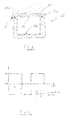
- the number 10 illustrates as a whole a horizontal freezer (also known as a "chest freezer") having a compartment 10a and a door 12 hinged at 14 to the structure of the freezer.
- the door is provided at the front with a control panel 12a provided with a visual display unit (not illustrated) associated with a user interface through which the user can for example set the desired temperature.
- the door is also provided, on top of a lower face 12b, with a temperature sensor 16 facing the compartment 10a.
- This sensor 16 is connected to the user interface card associated with the control panel 12a and both are connected to an electronic control unit (not illustrated) to which the control for the relay of the electric motor of the compressor (not illustrated) also leads.
- the solution for control according to the invention consists of a feedback control with a cycle time that is preferably fixed and a connection ratio I ( Figure 2) that is the regulation variable. At the beginning of every ON-OFF cycle of the compressor this variable
- the law underlying regulation is preferably linear, but it can also be third-degree and can be implemented even with the microchips currently in production at no extra cost. Obviously, more sophisticated regulation can be used, guaranteeing a limited error, limited overshoot and an optimal response time.
- the control system functions as follows.
- the temperature sensor 16 reads the temperature inside the compartment 10a and sends it to the microcontroller.
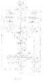
- the latter checks whether the temperature Tc is outside a certain range of regulation defined by the set temperature Ts and by the upper L C and lower L F values within which this temperature can vary. If the temperature Ts has been exceeded by more than L C (block 20) then the compressor is commanded to work at 100% connection (left branch of the algorithm, block 22) until the temperature Tc measured by the sensor is lower that the set temperature Ts (block 24). If the value is lower than the temperature Ts by more than L F (block 26) then the compressor is switched off (right branch of the algorithm, block 28) until the temperature Tc measured by the sensor is above the set temperature Ts (block 30).
- the system sets a fixed connection ratio, for example 50% (block 32) until the cycle time C is completed (blocks 34 and 36).
- (t+1)
- connection ratio calculated at 38 is lower than A and if the temperature Tc is not below the lower limit of regulation Lf (block 44), the system checks whether the connection ratio I determined at 38 is lower than a predetermined minimum value B (block 46) below which consumption would be too high. If the connection ratio is above B, the system repeats the control cycle constituted by the blocks 34, 36 and 38 in order to arrive, by successive approximations, at the optimum value for the connection ratio.
- the aforesaid values A and B for maximum and minimum connection ratios have been provided as emergency measures for the lifetime of the compressor.
- a normal compressor must in fact have a minimal "rest” time between being switched on and switched off again, of at least five minutes. If the ratio falls below levels that are too low, the motor should be kept switched off completely until the assigned temperature is reached again, rather than making the motor work for just a few minutes every half hour.
- the minimum ratio B is therefore set at 10%.
- the damping, the frequency of oscillations and the maximum overshoot of the regulation system depend on several factors, including the mass of the freezer contents and the regulation constants K and K'.
- the system regulates the operation of the horizontal freezer, establishing the connection ratio on the basis of the temperature recorded by the sensor 16 positioned in the compartment 10a.
- Optimal results in terms of energy savings have been obtained in comparison with those obtained on freezers using a traditional type of temperature control.
- the control algorithm can also provide for the possibility of determining the optimum time cycle for the freezer, for example starting from values for ambient temperature and/or from the temperature value set by the user and/or the value of the connection ratio of the compressor.
- the algorithm as well as following a logic such as that illustrated in Figure 3, will have the possibility of comparing the conditions in the surroundings and, from time to time, fixing the optimum cycle time C for such conditions.
- variable regulated to be the connection time of the compressor rather than its connection ratio.
- the ON-OFF cycle time will be variable in that the OFF time will not be fixed a priori by the algorithm itself but will be variable in relation to the operating conditions of the freezer, and in particular in relation to the time required in order to return to the set temperature.
- the variable regulated is the deactivation time of the compressor. In this case the ON time will not be fixed a priori by the algorithm, but will be variable in relation to the time required in order to return to the set temperature.
- the type of control according to the present invention can also be used to advantage for other types of refrigerators and freezers, for example refrigerators with or without a separate freezer compartment and upright freezers.
Landscapes
- Engineering & Computer Science (AREA)
- Physics & Mathematics (AREA)
- Mechanical Engineering (AREA)
- Thermal Sciences (AREA)
- General Engineering & Computer Science (AREA)
- Devices That Are Associated With Refrigeration Equipment (AREA)
Abstract
Description
- The present invention concerns a refrigerator, particularly a horizontal freezer, of the type comprising a food storage compartment, a cooling circuit provided with a compressor, a temperature sensor positioned in said compartment and a control system capable of controlling the compressor in relation to a signal from said temperature sensor.
- This type of horizontal freezer, in which the sensor it is preferably positioned on a lower face of the door that closes the compartment, has advantages over the traditional type of horizontal freezer, the hysteresis control of which is based on measuring the temperature on the evaporator. The sensor on the evaporator presents problems in terms of design, the thermal stresses of the sensor and the standardisation of parts, arising from the machining necessary in order to allow the passage of the wire connecting to the control card positioned near the door handle. Positioning the sensor on the door, near the user interface positioned on the handle, greatly simplifies electrical connections and reduces the number of cable junctions, with all the advantages of lower cost and greater reliability of the electrical appliance.
- In traditional freezers the temperature on the evaporator is measured by means of a sensor applied to the tube of the evaporator. A thermostat (mechanical or electronic) controls the switching on of the motor when the temperature of the evaporator goes above a predetermined upper limit (based on the set value for temperature), and controls switching off when this temperature falls below a lower limit.
- In horizontal freezers of the known type with a temperature sensor in the door, the same type of control is used as with the sensor on the evaporator, modifying the parameters of the thermostat. The temperature measured with the sensor in the new position is in fact less sensitive to the switching on and off of the motor, and is very similar to the temperature of the contents. The discrepancy between the two levels must therefore be much smaller if the temperature of the contents is to be kept very close to the set temperature, for example by a few tenths of a degree. The small deviation between the upper temperature and the lower temperature requires a microchip with greater precision in order to discriminate even to a hundredth of a degree. This characteristic can be found in microchips provided with an analogue-to-digital converter, which, however, are more expensive than the microchips used on traditional products with a sensor on the evaporator.
- Moreover, the system with a sensor on the door is more delicate than the previous one. For example, if the user opens the door as soon as the motor starts up, the temperature rises more quickly than intended and, since the upper level is extremely close, it could make the motor switch on after too short a time. Alternatively, when the freezer is empty, since the temperature of the sensor changes much more quickly than when it has a load, because of the greater convective motion of the air inside, the control would tend to produce cycles of just a few minutes. This is technically unacceptable because compressors have minimal OFF times. Switching off and on too rapidly would cause the motor to break down.
- Another important defect of freezers with a sensor in the door is the poor performance of the freezer. The cycles are very long and the temperatures of some frozen products oscillate with amplitudes of up to 2°C. The cycles can last for 3 or 4 hours, and even longer, and therefore the temperature pattern of the frozen products is extremely variable even if they have high thermal lag. With the current control, in fact, the cycle time cannot be controlled directly, but varies particularly with ambient temperature. Since it is known that the optimal performance of the freezer depends on a given cycle time, cycles that are too long or too short in freezers of the known type with a sensor in the door do not ensure optimal performance of the electrical appliance.
- With cycles that are too short, consumption rises because the compressor starts up too frequently while, with long cycles, the temperature of the frozen foodstuffs fluctuates at great amplitudes, and therefore more energy than necessary is expended in order to ensure that the contents are kept at the required temperature.
- The aim of the present invention is to overcome the aforesaid disadvantages, while maintaining all the existing advantages of a horizontal freezer with a temperature sensor in the door.
- This aim is achieved through the characteristics listed in the attached claims.
- One of the main characteristics of the present invention is the ability of the control system of the freezer to define, on the base of the temperature reported by the sensor, a value linked to the connection time of the compressor. This value is preferably the connection ratio of the compressor, keeping the cycle time to a predetermined constant value. According to another characteristic of the invention, the control system of the freezer is also capable of determining the cycle time in relation to the temperature pattern monitored in the previous cycles, with the possibility of subsequently auto-adapting the control system to the operating conditions of the freezer (ambient temperature, amount of contents, frequency of door opening, efficiency of insulation etc.). According to another embodiment of the invention, the value fixed by the system is actually the activation time of the compressor, the deactivation time being free to fluctuate in relation to the time required in order to return to the set temperature.
- According to another embodiment of the invention, the value fixed by the system is actually the deactivation time of the compressor, the activation time being free to fluctuate in relation to the time required in order to return to the set temperature.
- Other advantages and characteristics of a refrigerator according to the present invention will become apparent from the following detailed description, provided purely as a non-exhaustive example and with reference to the attached drawings in which:
- Figure 1 is a schematic drawing in cross-section of a horizontal freezer according to the invention,
- Figure 2 is a schematic diagram that illustrates the ON-OFF operation of the compressor used in the freezer in Figure 1,
- Figure 3 is an outline diagram that illustrates one of the possible control algorithms used in the freezer according to the invention, and
- Figure 4 is a temperature/time diagram for the freezer according to the invention, and the related diagram that illustrates the variation in the connection ratio of the compressor.
- With reference to the drawings, the number 10 illustrates as a whole a horizontal freezer (also known as a "chest freezer") having a compartment 10a and a
door 12 hinged at 14 to the structure of the freezer. The door is provided at the front with acontrol panel 12a provided with a visual display unit (not illustrated) associated with a user interface through which the user can for example set the desired temperature. The door is also provided, on top of alower face 12b, with atemperature sensor 16 facing the compartment 10a. Thissensor 16 is connected to the user interface card associated with thecontrol panel 12a and both are connected to an electronic control unit (not illustrated) to which the control for the relay of the electric motor of the compressor (not illustrated) also leads. - The solution for control according to the invention consists of a feedback control with a cycle time that is preferably fixed and a connection ratio I (Figure 2) that is the regulation variable. At the beginning of every ON-OFF cycle of the compressor this variable | is determined as a function of the connection ratio of the previous cycle, the temperature set and the temperature measured.
- The law underlying regulation is preferably linear, but it can also be third-degree and can be implemented even with the microchips currently in production at no extra cost. Obviously, more sophisticated regulation can be used, guaranteeing a limited error, limited overshoot and an optimal response time.
- The algorithm for the electronic card associated with the control unit of the freezer is illustrated in Figure 3, where the constants of the diagram Lc, LF, C, K and K' are determined on the basis of experimental tests:
- Lc and LF are the two limit values that determine the regulation zone. If the temperature Tc reported by the

sensor 16 is found to be above this zone (Tc - Ts > LC, where Ts is the set temperature) the motor runs continuously (and therefore with connection ratio equal to 100%), until the measured temperature reaches the set temperature Ts; if it is below this (Tc - Ts < LF), the motor remains off (connection ratio equal to 0%) until thesensor 16 reaches the set temperature with zero error; - C is the cycle time, and is established essentially on the basis of consumption tests. Every model or capacity of freezer in fact has a minimum consumption for a particular value of such a variable;

- K and K' are the regulation constants, which express the degree of influence of the error measured on the variation of connection in the next cycle, and determine the frequency of temperature oscillations before stabilisation;

- A and B are connection ratios that determine respectively the continuous operation or deactivation of the compressor, and are preferably equal to approximately 84% and 10%.

- The control system functions as follows. The
temperature sensor 16 reads the temperature inside the compartment 10a and sends it to the microcontroller. The latter checks whether the temperature Tc is outside a certain range of regulation defined by the set temperature Ts and by the upper LC and lower LF values within which this temperature can vary. If the temperature Ts has been exceeded by more than LC (block 20) then the compressor is commanded to work at 100% connection (left branch of the algorithm, block 22) until the temperature Tc measured by the sensor is lower that the set temperature Ts (block 24). If the value is lower than the temperature Ts by more than LF (block 26) then the compressor is switched off (right branch of the algorithm, block 28) until the temperature Tc measured by the sensor is above the set temperature Ts (block 30). When the set temperature Ts is substantially reached (whether from higher temperatures or from lower temperatures), the system sets a fixed connection ratio, for example 50% (block 32) until the cycle time C is completed (blocks 34 and 36). At the end of the cycle, the function |(t+1) = |(t) + K(Tc(t)-Ts) + K'(Tc(t)-Tc(T-1)) is applied and, on the basis of the actual temperature Tc reached after this cycle, the temperature reached at the end of the previous cycle and the regulation constants K and K', this determines the connection ratio that will be used in the next cycle (block 38). In the aforesaid equation, |(t+1) represents the connection ratio of the compressor to be used in the next cycle, |(t) the connection ratio in the current cycle, Tc(t) the temperature recorded at the end of the current cycle and Tc(T-1) is the temperature recorded at the end of the previous cycle. The connection ratio calculated inblock 38 will actually be used in the next cycle, unless, in block 40, it is found that the temperature range is still over the aforesaid upper limit Lc. If this condition is not found, the connection ratio determined in block 40 is compared inblock 42 with a predetermined connection ratio value A over which it is not however convenient to make the compressor work, a 100% connection being preferable. If the connection ratio calculated at 38 is lower than A and if the temperature Tc is not below the lower limit of regulation Lf (block 44), the system checks whether the connection ratio I determined at 38 is lower than a predetermined minimum value B (block 46) below which consumption would be too high. If the connection ratio is above B, the system repeats the control cycle constituted by theblocks - The aforesaid values A and B for maximum and minimum connection ratios have been provided as emergency measures for the lifetime of the compressor. A normal compressor must in fact have a minimal "rest" time between being switched on and switched off again, of at least five minutes. If the ratio falls below levels that are too low, the motor should be kept switched off completely until the assigned temperature is reached again, rather than making the motor work for just a few minutes every half hour. The minimum ratio B is therefore set at 10%. The damping, the frequency of oscillations and the maximum overshoot of the regulation system depend on several factors, including the mass of the freezer contents and the regulation constants K and K'.
- In the embodiment described here the system regulates the operation of the horizontal freezer, establishing the connection ratio on the basis of the temperature recorded by the
sensor 16 positioned in the compartment 10a. Optimal results in terms of energy savings have been obtained in comparison with those obtained on freezers using a traditional type of temperature control. Obviously, the control algorithm can also provide for the possibility of determining the optimum time cycle for the freezer, for example starting from values for ambient temperature and/or from the temperature value set by the user and/or the value of the connection ratio of the compressor. In this case the algorithm, as well as following a logic such as that illustrated in Figure 3, will have the possibility of comparing the conditions in the surroundings and, from time to time, fixing the optimum cycle time C for such conditions. Another embodiment of the algorithm according to the invention provides for the variable regulated to be the connection time of the compressor rather than its connection ratio. In this case the ON-OFF cycle time will be variable in that the OFF time will not be fixed a priori by the algorithm itself but will be variable in relation to the operating conditions of the freezer, and in particular in relation to the time required in order to return to the set temperature. Similarly, according to another embodiment of the invention, the variable regulated is the deactivation time of the compressor. In this case the ON time will not be fixed a priori by the algorithm, but will be variable in relation to the time required in order to return to the set temperature. - Although, in the description of the embodiment example, reference has been made mainly to a horizontal freezer, the type of control according to the present invention can also be used to advantage for other types of refrigerators and freezers, for example refrigerators with or without a separate freezer compartment and upright freezers.
Claims (11)
- Domestic refrigerator, particularly freezer, of the type comprising a food storage compartment, a cooling circuit provided with a compressor, a temperature sensor (16) positioned in said compartment and a control system capable of controlling the compressor in relation to a signal from said temperature sensor, characterised by the fact that the control system is capable of defining, on the basis of the temperature reported by said sensor (16), a value linked to the connection time of the compressor with the aim of optimising the performance of the refrigerator.
- Refrigerator according to Claim 1, characterised by the fact that said value is the connection ratio in an ON-OFF cycle of the compressor, the cycle time (C) being fixed at a predetermined value.
- Refrigerator according to Claim 2, characterised by the fact that the control system is also capable of defining an optimum time cycle (C) for the compressor.
- Refrigerator according to Claim 1, characterised by the fact that said value is the connection time of the compressor.
- Refrigerator according to Claim 1, characterised by the fact that said value is the deactivation time of the compressor.
- Refrigerator according to any one of the preceding claims, particularly a horizontal freezer provided with an upper horizontal door, characterised by the fact that the temperature sensor (16) is positioned on said door (12) on its face facing the compartment (10a).
- Refrigerator according to Claim 2 or 3, characterised by the fact that the connection ratio of the compressor is calculated on the basis of the following equation:

where |(t) is the connection ratio of the compressor calculated in the current cycle, |(t+1) is the connection ratio to be used in the next cycle, K and K' are the regulation constants, Tc(t) is the temperature recorded at the end of the current cycle, Tc(T-1) is the temperature recorded at the end of the previous cycle and Ts is the set temperature. - Refrigerator according to Claim 7, characterised by the fact that the control system is capable of comparing the connection ratio (I) calculated with a predetermined maximum value (A), and making the compressor work at a connection ratio equal to 100% in the next cycle if the calculated connection ratio exceeds said maximum value (A).
- Refrigerator according to Claim 7, characterised by the fact that the control system is capable of comparing the calculated connection ratio (I) with a predetermined minimum value (B), and of making the compressor work at a connection ratio equal to 0% in the next cycle if the calculated connection ratio is lower than said minimum value (B).
- Method for regulating the temperature in a domestic refrigerator, particularly in a horizontal freezer (10) provided with a food storage compartment (10a), a cooling circuit with a compressor and a temperature sensor (16) positioned in said compartment, characterised by the fact that it comprises the definition of a regulated value linked to the connection time of the compressor.
- Method according to Claim 10, characterised by the fact that it comprises the comparison of the recorded temperature (Tc) with a predetermined set value and with two values (LC, LF) capable of defining a regulation range within which said set value (Ts) is comprised, the definition of the connection ratio (I) in an ON-OFF cycle of the compressor at 100% and 0% respectively if the recorded temperature (Tc) is found to be above or below this regulation range, the definition of a connection ratio (I) with a value corresponding to the following equation |(t+1) = |(t) + K(Tc(t)-Ts) + K'(Tc(t)-Tc(T-1)) if the recorded temperature is found to be within said regulation range, where |(t) is the connection ratio of the compressor calculated in the current ON-OFF operation cycle of the compressor, |(t+1) is the connection ratio to be used in the next cycle, K and K' are the regulation constants, Tc(t) is the temperature recorded at the end of the current cycle, Tc(T-1) is the temperature recorded at the end of the previous cycle and Ts is the set temperature.
Applications Claiming Priority (1)
| Application Number | Priority Date | Filing Date | Title |
|---|---|---|---|
| ITVA20030039 ITVA20030039A1 (en) | 2003-10-21 | 2003-10-21 | HORIZONTAL FREEZER. |
Publications (2)
| Publication Number | Publication Date |
|---|---|
| EP1655557A2 true EP1655557A2 (en) | 2006-05-10 |
| EP1655557A3 EP1655557A3 (en) | 2013-03-27 |
Family
ID=35840300
Family Applications (1)
| Application Number | Title | Priority Date | Filing Date |
|---|---|---|---|
| EP04105137A Withdrawn EP1655557A3 (en) | 2003-10-21 | 2004-10-19 | Horizontal freezer |
Country Status (2)
| Country | Link |
|---|---|
| EP (1) | EP1655557A3 (en) |
| IT (1) | ITVA20030039A1 (en) |
Family Cites Families (8)
| Publication number | Priority date | Publication date | Assignee | Title |
|---|---|---|---|---|
| AT292756B (en) * | 1967-11-10 | 1971-09-10 | Friac | Device for temperature control in freezers or freezers |
| JPH0791792A (en) * | 1993-09-28 | 1995-04-04 | Toshiba Corp | Frozen stocker |
| DE19505706A1 (en) * | 1995-02-20 | 1996-08-22 | Aeg Hausgeraete Gmbh | Control device and method for temperature control in cooling devices |
| IT1301875B1 (en) * | 1998-07-29 | 2000-07-07 | Whirlpool Co | SELF-ADAPTIVE CONTROL FOR THE REGULATION OF REFRIGERATORS AND FREEZERS |
| JP3732032B2 (en) * | 1999-01-27 | 2006-01-05 | シャープ株式会社 | refrigerator |
| DE69916231D1 (en) * | 1999-02-19 | 2004-05-13 | Ranco Inc Of Delaware Wilmingt | Regulator and method for controlling the temperature in a refrigerator |
| KR100597732B1 (en) * | 2000-09-07 | 2006-07-07 | 삼성전자주식회사 | Refrigerator Control Method |
| IT1314887B1 (en) * | 2000-12-13 | 2003-01-16 | Magnetek Spa | METHOD FOR THE REDUCTION OF ENERGY CONSUMPTION IN A REFRIGERATING MACHINE, AND REFRIGERATING MACHINE OPERATING ACCORDING TO THAT METHOD |
-
2003
- 2003-10-21 IT ITVA20030039 patent/ITVA20030039A1/en unknown
-
2004
- 2004-10-19 EP EP04105137A patent/EP1655557A3/en not_active Withdrawn
Non-Patent Citations (1)
| Title |
|---|
| None * |
Also Published As
| Publication number | Publication date |
|---|---|
| EP1655557A3 (en) | 2013-03-27 |
| ITVA20030039A1 (en) | 2005-04-22 |
Similar Documents
| Publication | Publication Date | Title |
|---|---|---|
| US6606870B2 (en) | Deterministic refrigerator defrost method and apparatus | |
| US8209991B2 (en) | Cooling storage and method of operating the same | |
| CA2409539C (en) | Methods and apparatus for controlling compressor speed | |
| CN107592905B (en) | Refrigerator and control method thereof | |
| US6216478B1 (en) | Operation speed change system and method for refrigerator | |
| EP1398584B1 (en) | Method for controlling a multiple cooling compartment refrigerator, and refrigerator using such method | |
| CA2409641C (en) | Sealed system multiple speed compressor and damping control | |
| EP3832237B1 (en) | Method for controlling refrigerator | |
| US6116036A (en) | Self regulating device for controlling refrigerators and freezers | |
| US6684656B2 (en) | Low energy appliance control apparatus and method | |
| EP1157247B1 (en) | Controller and method for controlling the temperature in a refrigerator | |
| EP1714095B1 (en) | Heater cycling for improved oil return | |
| US7665317B2 (en) | Method for controlling a refrigeration appliance | |
| US5931010A (en) | Method and apparatus for controlling a temperature of a cooked food chilling chamber in a refrigerator | |
| EP0388726B1 (en) | Refrigerating appliance with single thermostatic temperature control device | |
| US3390718A (en) | Household refrigerator including automatic icemaker and control means therefor | |
| EP2636976B1 (en) | Hybrid refrigerator and control method thereof | |
| KR20210026836A (en) | Refrigerator and method for controlling operation of the same | |
| GB2133586A (en) | Temperature control of a refrigerator | |
| KR910001337Y1 (en) | Solenoid Damper Control Circuit | |
| KR100452994B1 (en) | Control method for refrigeration system | |
| KR19990033983A (en) | Cold and hot aging switching device and method of the Kimchi container refrigerator | |
| KR970066451A (en) | Defrost control method of refrigerator | |
| KR20070072791A (en) | Refrigerator Control Method | |
| JPH06109351A (en) | Showcase operation controller |
Legal Events
| Date | Code | Title | Description |
|---|---|---|---|
| PUAI | Public reference made under article 153(3) epc to a published international application that has entered the european phase |
Free format text: ORIGINAL CODE: 0009012 |
|
| AK | Designated contracting states |
Kind code of ref document: A2 Designated state(s): AT BE BG CH CY CZ DE DK EE ES FI FR GB GR HU IE IT LI LU MC NL PL PT RO SE SI SK TR |
|
| AX | Request for extension of the european patent |
Extension state: AL HR LT LV MK |
|
| PUAL | Search report despatched |
Free format text: ORIGINAL CODE: 0009013 |
|
| AK | Designated contracting states |
Kind code of ref document: A3 Designated state(s): AT BE BG CH CY CZ DE DK EE ES FI FR GB GR HU IE IT LI LU MC NL PL PT RO SE SI SK TR |
|
| AX | Request for extension of the european patent |
Extension state: AL HR LT LV MK |
|
| RIC1 | Information provided on ipc code assigned before grant |
Ipc: F25B 49/02 20060101AFI20130215BHEP |
|
| 17P | Request for examination filed |
Effective date: 20130417 |
|
| AKX | Designation fees paid |
Designated state(s): DE FR GB IT PL |
|
| 17Q | First examination report despatched |
Effective date: 20131204 |
|
| STAA | Information on the status of an ep patent application or granted ep patent |
Free format text: STATUS: EXAMINATION IS IN PROGRESS |
|
| GRAP | Despatch of communication of intention to grant a patent |
Free format text: ORIGINAL CODE: EPIDOSNIGR1 |
|
| STAA | Information on the status of an ep patent application or granted ep patent |
Free format text: STATUS: GRANT OF PATENT IS INTENDED |
|
| INTG | Intention to grant announced |
Effective date: 20180514 |
|
| STAA | Information on the status of an ep patent application or granted ep patent |
Free format text: STATUS: THE APPLICATION IS DEEMED TO BE WITHDRAWN |
|
| 18D | Application deemed to be withdrawn |
Effective date: 20180925 |