EP1655401A1 - Washing machine combined with dryer - Google Patents
Washing machine combined with dryer Download PDFInfo
- Publication number
- EP1655401A1 EP1655401A1 EP05291434A EP05291434A EP1655401A1 EP 1655401 A1 EP1655401 A1 EP 1655401A1 EP 05291434 A EP05291434 A EP 05291434A EP 05291434 A EP05291434 A EP 05291434A EP 1655401 A1 EP1655401 A1 EP 1655401A1
- Authority
- EP
- European Patent Office
- Prior art keywords
- filter
- lint
- washing machine
- air
- lint filter
- Prior art date
- Legal status (The legal status is an assumption and is not a legal conclusion. Google has not performed a legal analysis and makes no representation as to the accuracy of the status listed.)
- Withdrawn
Links
- 238000005406 washing Methods 0.000 title claims abstract description 82
- 238000010981 drying operation Methods 0.000 claims description 12
- 238000009434 installation Methods 0.000 claims description 4
- 238000003780 insertion Methods 0.000 claims description 3
- 230000037431 insertion Effects 0.000 claims description 3
- 239000003779 heat-resistant material Substances 0.000 claims description 2
- 230000008878 coupling Effects 0.000 claims 1
- 238000010168 coupling process Methods 0.000 claims 1
- 238000005859 coupling reaction Methods 0.000 claims 1
- XLYOFNOQVPJJNP-UHFFFAOYSA-N water Substances O XLYOFNOQVPJJNP-UHFFFAOYSA-N 0.000 description 28
- 239000003599 detergent Substances 0.000 description 11
- 238000007599 discharging Methods 0.000 description 2
- 238000001035 drying Methods 0.000 description 2
- 239000002979 fabric softener Substances 0.000 description 2
- 239000013505 freshwater Substances 0.000 description 2
- 238000012986 modification Methods 0.000 description 2
- 230000004048 modification Effects 0.000 description 2
- 230000000903 blocking effect Effects 0.000 description 1
- 239000000498 cooling water Substances 0.000 description 1
- 239000000428 dust Substances 0.000 description 1
- 230000033001 locomotion Effects 0.000 description 1
- 239000000203 mixture Substances 0.000 description 1
- 239000002245 particle Substances 0.000 description 1
- 239000008237 rinsing water Substances 0.000 description 1
- 238000007789 sealing Methods 0.000 description 1
- 238000000926 separation method Methods 0.000 description 1
- 239000000126 substance Substances 0.000 description 1
Images



Classifications
-
- D—TEXTILES; PAPER
- D06—TREATMENT OF TEXTILES OR THE LIKE; LAUNDERING; FLEXIBLE MATERIALS NOT OTHERWISE PROVIDED FOR
- D06F—LAUNDERING, DRYING, IRONING, PRESSING OR FOLDING TEXTILE ARTICLES
- D06F39/00—Details of washing machines not specific to a single type of machines covered by groups D06F9/00 - D06F27/00
- D06F39/10—Filtering arrangements
-
- D—TEXTILES; PAPER
- D06—TREATMENT OF TEXTILES OR THE LIKE; LAUNDERING; FLEXIBLE MATERIALS NOT OTHERWISE PROVIDED FOR
- D06F—LAUNDERING, DRYING, IRONING, PRESSING OR FOLDING TEXTILE ARTICLES
- D06F37/00—Details specific to washing machines covered by groups D06F21/00 - D06F25/00
- D06F37/26—Casings; Tubs
- D06F37/267—Tubs specially adapted for mounting thereto components or devices not provided for in preceding subgroups
-
- D—TEXTILES; PAPER
- D06—TREATMENT OF TEXTILES OR THE LIKE; LAUNDERING; FLEXIBLE MATERIALS NOT OTHERWISE PROVIDED FOR
- D06F—LAUNDERING, DRYING, IRONING, PRESSING OR FOLDING TEXTILE ARTICLES
- D06F39/00—Details of washing machines not specific to a single type of machines covered by groups D06F9/00 - D06F27/00
- D06F39/12—Casings; Tubs
-
- D—TEXTILES; PAPER
- D06—TREATMENT OF TEXTILES OR THE LIKE; LAUNDERING; FLEXIBLE MATERIALS NOT OTHERWISE PROVIDED FOR
- D06F—LAUNDERING, DRYING, IRONING, PRESSING OR FOLDING TEXTILE ARTICLES
- D06F58/00—Domestic laundry dryers
- D06F58/20—General details of domestic laundry dryers
- D06F58/22—Lint collecting arrangements
-
- D—TEXTILES; PAPER
- D06—TREATMENT OF TEXTILES OR THE LIKE; LAUNDERING; FLEXIBLE MATERIALS NOT OTHERWISE PROVIDED FOR
- D06F—LAUNDERING, DRYING, IRONING, PRESSING OR FOLDING TEXTILE ARTICLES
- D06F25/00—Washing machines with receptacles, e.g. perforated, having a rotary movement, e.g. oscillatory movement, the receptacle serving both for washing and for centrifugally separating water from the laundry and having further drying means, e.g. using hot air
Definitions
- the present invention relates to a washing machine, and more particularly, to a washing machine combined with a dryer, in which a lint filter assembly is detachably installed to collect and remove foreign substances such as lint generated during a heat drying operation.
- a washing machine is a home appliance for washing clothes automatically.
- a typical washing machine uses an electric motor as a driving unit to agitate clothes together with water containing detergent to remove dirt from the clothes.
- the washing process of the washing machine generally includes washing, rinsing, spin-drying, and/or heat-drying operations.
- Washing machines can be classified into a drum type washing machine, an agitator type washing machine, and a pulsator type washing machine.
- the drum type washing machine includes a plurality of lifters inside of a drum to lift up and drop down clothes in the drum as the drum is rotated about a horizontal axis at a low speed. Therefore, the clothes can be cleaned by the collision with water containing detergent.
- washing machine combined with a dryer is recently introduced to satisfy user's demand.
- clothes are heat dried after washed, rinsed, and spin dried.
- the washing machine combined with the dryer can be classified into a condenser type and a vented type depending on a drying method.
- the washing machine combined with the condenser type dryer removes residual moisture from clothes by circulating air through a drum, a heat exchanger, and a heater without discharging the air out of the washing machine until the heat drying operation is completed. That is, the air becomes moist after passing through the drum, the moist air cools down at the heat exchanger by exchanging heat with a cooling water, the moisture in the air condenses and drops down to the bottom of the tub as the moist air cools down, and the air is heated again by the heater and then enters the drum again.
- the moist air which is discharged from the washing machine combined with the vented type dryer, contains lint such as fluff, thereby contaminating the indoor air.
- the lint in the moist air falls down and builds up while it is discharged from the tub to the outside through the vent duct.
- the lint builds up on a pleated surface of the connecting pipe connected between the tub and the vent duct.
- the build-up of the lint becomes bigger according to the time of use, blocking the vent duct.
- the build-up of the lint increases the possibility of fire. Therefore, there is an increasing need for a structure that can remove the problems related to the lint.
- the present invention is directed to a washing machine combined with a dryer that substantially obviates one or more problems due to limitations and disadvantages of the related art.
- An object of the present invention is to provide a washing machine combined with a vented type dryer, in which an air-vent line, including an air-vent hose connected between a tub and the air-vent duct, is prevented from being plugged by lint generated during a heat drying operation.
- Another object of the present invention is to provide a washing machine combined with a dryer, in which lint generated during a heat drying operation is prevented from building up in an air-vent line and therefore the possibility of fire reduces.
- a further another object of the present invention is to provide a washing machine combined with a dryer that has a lint filter assembly to remove lint, the lint filter assembly being designed such that a user can easily install and replace it.
- a washing machine combined with a dryer including: a cabinet; a tub installed in the cabinet; an air-vent hose installed at an outer surface of the tub; a lint filter assembly having one end connected to the air-vent hose to remove lint from air discharged from the tub; and an air-vent duct connected to the other end of the lint filter assembly.
- a washing machine combined with a dryer, including: a cabinet; a top plate to cover a top of the cabinet; a tub installed in the cabinet; a lint filter assembly including a lint filter to remove lint from a moist air discharged from the tub, a filter housing to receive the lint filter, and a seal fitted between the lint filter and the filter housing to prevent air leakage; and a dryer duct installed above the tub to supply a hot air to the tub during a heat drying operation.
- a washing machine combined with a dryer, including: a lint filter including a mesh type filter, a filter frame around the mesh type filter, and a handgrip formed on a top of the filter frame; a seal fitted around the lint filter; a filter housing including a filter chamber to receive the lint filter, an air inlet to introduce a moist air discharged from a tub, and an air outlet to discharge the moist air introduced through the air inlet; and a filter cover mounted on an end of the filter chamber.
- a washing machine combined with a dryer, including: a tub; an air-vent hose connected to a rear of the tub; and a detachable lint filter assembly connected with the air-vent hose to remove lint from a moist air discharged through the air-vent hose.
- the lint separated from clothes during a heat drying operation can be collected and regularly removed, such that the lint does not build up in the air-vent duct.
- the collected lint can be regularly removed by a user, the possibility of fire in the washing machine due to the build-up of the lint is reduced.
- the lint filter can be easily detached from the washing machine, the user does not need to call a repairman to clean or replace the lint filter, thereby increasing user convenience.
- Fig. 1 is a perspective view of a washing machine combined with a dryer in which a lint filter assembly is installed according to the present invention
- Fig. 2 is a side sectional view of the washing machine combined with the dryer depicted in Fig. 1;
- Fig. 3 is an exploded cut-away view of a lint filter assembly according to the present invention.
- Fig. 4 is an enlarged sectional view showing installation of the lint filter assembly depicted in Fig. 3;
- Fig. 5 is a perspective view of a washing machine combined with a dryer in which a lint filter assembly is installed according to another embodiment of the present invention.
- FIG. 1 is a perspective view of a washing machine combined with a dryer in which a lint filter assembly is installed according to the present invention
- Fig. 2 is a side sectional view of the washing machine combined with the dryer depicted in Fig. 1.
- a washing machine combined with a dryer 100 includes: an enclosing cabinet 103; a top plate 101 mounted on a top of the cabinet 103; a base plate 102 installed on a bottom of the cabinet 103; a front cover 105 mounted on a front of the cabinet 103; a door 104 rotatably installed at a center of the front cover 105; a control panel 500 installed at an upper portion of the front cover 105, the control panel 500 having a plurality of input buttons and a display; a detergent dispenser drawer 510 inserted into a side of the control panel 500 to receive detergent or fabric softener.
- the washing machine combined with the dryer 100 includes a tub 130 installed in the cabinet 103 to receive water (or mixture of water and detergent), a drum 120 installed in the tub 130 to receive clothes, and a driving motor 110 mounted on a back of the tub 130 to rotate the drum 120.
- the driving motor 110 includes a shaft 111 connected to a rear of the drum 120.
- the washing machine combined with the dryer 100 includes a dryer duct 400 installed between the cabinet 103 and a top of the tub 130 to introduce a surrounding air into the tub 130, an air-vent hose 310 connected to a top rear of the tub 130 to vent a moist air from the drum 120 to the outside, and a lint filter assembly 200 removably installed in the air-vent hose 310 to remove lint from the moist air passing therethrough during a heat drying operation.
- the term "lint” is used to refer to little pieces of thread and fluff, dust, and other particles that are contained in the air passing through the lint filter assembly 200.
- the lint filter assembly 200 has one end connected to the tub 130 and the other end connected to an air-vent duct 300.
- the dryer duct 400 includes a blower fan 420 installed therein to draw air and a heater 410 to apply heat to the drawn air. Also, the dryer duct 400 includes a fan motor 430 to drive the blower fan 420.
- the washing machine combined with the dryer 100 includes a water drain tube 141 of which one end is connected to a bottom of the tub 130 to discharge water contaminated during a washing operation or a rinsing operation, a water drain pump 140 connected to the other end of the water drain tube 141 to pump out the contaminated water, and a water drain hose 142 to discharge the contaminated water pumped by the water drain pump 140 to the outside.
- a user opens the door 104, loads clothes in the drum 120 through the opened door 104, and closes the door 104.
- the user selects operating conditions using the control panel 500 and presses a start button on the control panel 500.
- water is supplied to the detergent dispenser drawer 510 through a water inlet hose (not shown).
- the water mixed with the detergent (washing water) enters the tub 130 through a bellows (not shown) connected between the detergent dispenser drawer 510 and the tub 130.
- the water is supplied until the tub 130 is filled with the water to a predetermined level.
- the driving motor 110 drives the drum 120 to carry out a washing operation.
- the clothes and the washing water is lifted up by the rotation of the drum 120 and then dropped down.
- the dirt can be removed from the clothes during the washing operation.
- the washing water contaminated is discharged and fresh water is supplied to the tub 130 to carry out a rinsing operation.
- the driving motor 110 is stopped and the water drain pump 140 is operated to drain the contaminated water from the tub 130 through the water drain tube 141 toward the water drain hose 142.
- the fresh water is supplied to the tub 130 for the rinsing operation.
- a spin drying operation is carried out after the rinsing operation to remove residual water from the clothes, and then a heat drying operation is optionally carried out.
- the blower fan 420 installed in the dryer duct 400 is driven to draw in a surrounding air from between the cabinet 103 and the tub 130.
- the heater 410 applies heat to the drawn-in air, and the heated air is directed into the tub 130 along the dryer duct 400.
- the heated air flows from the tub 130 into the drum 120 through the plurality of holes 141 defined in the drum 120.
- the heated air having a low humidity, takes moisture from the clothes and therefore it becomes a moist air.
- the moist air is discharged to the outside of the washing machine 100 through air-vent hose 310, the lint filter assembly 200, and the air-vent duct 300.
- the lint filter assembly 200 collects lint from the moist air passing therethrough.
- the collected lint builds up on a filter (as will be described later) of the lint filter assembly 200.
- a user can detach the filter from the washing machine 100 to clean it.
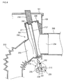
- Fig. 3 is an exploded cut-away view of a lint filter assembly according to the present invention
- Fig. 4 is an enlarged sectional view showing installation of the lint filter assembly depicted in Fig. 3.
- the lint filter assembly 200 is located between the tub 130 and the cabinet 103 to connect the air-vent hose 310 and the air-vent duct 300.
- the lint filter assembly 200 includes a lint filter 210 to collect lint, a filter housing 230 in which the lint filter 210 is detachably inserted, and a filter cover 220 coupled to a top of the filter housing 230, and a seal 240 fitted around the lint filter 210.
- the lint filter 210 includes a mesh type filter 212, a filter frame 211 around the filter 212 to hold the filter 212, a handgrip 213 extended from a top of the filter frame 211 for a use to hold it, and a seal groove 214 defined between the filter frame 211 and the handgrip 213 with a predetermine depth to receive the seal 240.
- the handgrip 213 is sized such that it protrudes from the top plate 101 by a predetermined length when the lint filter 210 is completely inserted. Therefore, a use can easily detach the lint filter 210 from the washing machine 100 by simply pulling the handgrip 213 out.
- the filter frame 211 defines a hooking groove 215 at its lower end with a predetermined depth to couple with a hooking tab (as will be described later) of the filter housing 230, thereby preventing the lint filter 210 from shaking and moving out from the installed position. Since a hot, moist air discharged from the drum 120 is directed to the filter 212, the filter 212 may be made of heat resistant material for durability against the high-temperature air passing therethrough.
- the filter housing 230 includes a filter chamber 231 having a substantially the same height as the filter frame 211 to receive the lint filter 210, an air inlet 233 extended from one side of the filter chamber 231 for connection with the air-vent hose 310, and an air outlet 234 extendedly from the other side of the filter chamber 231 for connection with the air-vent duct 300. Since the air inlet 233 and the air outlet 234 are formed in opposite directions to each other, air can smoothly flow from the air-vent hose 310 to the air-vent duct 300 after passing through the lint filter 210.
- the filter housing 230 includes a mounting groove 236 at an inner bottom to receive the lower end of the lint filter 210, a bottom guide rib 235 protruded along one side of the mounting groove 236 with a predetermined height, a hooking tab 237 protruded from the other side of the mounting groove 236 toward the bottom guide rib 235, and side guide ribs 232 at an inner side face of the filter chamber 231.
- the side guide ribs 232 are formed in the insertion direction of the lint filter 210, i.e., in a vertical direction, to guide the insertion of the lint filter 210.
- the side guide ribs 232 are two in number and are spaced apart from each other to receive the filter frame 211 therebetween. Therefore, air leakage can be prevented between the filter frame 211 and the inner wall of the filter chamber 231.
- the bottom guide rib 235 is formed on the inner bottom of the filter housing 230 to exactly and tightly receive the lower end of the lint filter 210. Also, since the lower end of the filter frame 211 is inserted into the mounting groove 236, air leakage can be prevented between the lower end of the filter frame 211 and the filter housing 230.
- the hooking tab 237 of the filter housing 230 snaps into the hooking groove 215 of the filter frame 211 to lock the filter frame 211, thereby preventing separation of the lint filter 210.
- the filter cover 220 covers the opened top of the filter housing 230, i.e., the opened top of the filter chamber 231.
- the filter cover 220 defines a filter inserting slot 221 to receive the lint filter 210.
- the seal 240 fitted around the lint filter 210 is brought into tight contact with the inner surface of the filter inserting slot 221, thereby hermetically sealing the gap.
- a user holds the handgrip 213 of the lint filter 210 with a hand and then he/she inserts the lint filter 210 into the filter housing 230 with the lower end of the filter frame 211 pointing to the filter inserting slot 221.
- the inserted lint filter 210 is guided by the side guide ribs 232 until the lower end of the filter frame 211 is completely inserted into the mounting groove 236 of the filter housing 230.
- the bottom guide rib 235 of the filter housing 230 exactly places the lower end of the filter frame 211 into the mounting groove 236, and the hooking tab 237 of the filter housing 230 snaps into the hooking groove 215 of the filter frame 211.
- the seal 240 around the lint filter 210 hermetically seals the gap between the lint filter 210 and the filter inserting slot 221 of the filter cover 220. Therefore, the lint filter 210 can collect lint from a moist air discharged from the tub 130 through the air-vent hose 230, and it can be detached from the washing machine 100 to shake build-up of the lint off the filter 212.
- the side guide ribs 232 are inclined at a predetermined angle to the vertical to receive the lint filter 210 at the predetermined angle, such that a user can easily insert and detach the lint filter 210 by pushing and pulling the handgrip 213.
- seal 240 fitted into the seal groove 214 of the handgrip 213, may be made of rubber or the like to hermetically seal the gap between the lint filter 210 and the filter cover 220.
- Fig. 5 is a perspective view of a washing machine combined with a dryer in which a lint filter assembly is installed according to another embodiment of the present invention.
- the lint filter assembly 200 is installed at a side of the cabinet, such that a user can insert and detach the lint filter 210 into and from the side.
- the filter chamber 231 of the filter housing 230 at a side of the washing machine 100, and the cabinet 103 defines a slot to receive the lint filter 210.
Landscapes
- Engineering & Computer Science (AREA)
- Textile Engineering (AREA)
- Detail Structures Of Washing Machines And Dryers (AREA)
Abstract
Description
- The present invention relates to a washing machine, and more particularly, to a washing machine combined with a dryer, in which a lint filter assembly is detachably installed to collect and remove foreign substances such as lint generated during a heat drying operation.
- A washing machine is a home appliance for washing clothes automatically. A typical washing machine uses an electric motor as a driving unit to agitate clothes together with water containing detergent to remove dirt from the clothes. The washing process of the washing machine generally includes washing, rinsing, spin-drying, and/or heat-drying operations.
- Washing machines can be classified into a drum type washing machine, an agitator type washing machine, and a pulsator type washing machine.
- The drum type washing machine includes a plurality of lifters inside of a drum to lift up and drop down clothes in the drum as the drum is rotated about a horizontal axis at a low speed. Therefore, the clothes can be cleaned by the collision with water containing detergent.
- Meanwhile, a washing machine combined with a dryer is recently introduced to satisfy user's demand. In this washing machine, clothes are heat dried after washed, rinsed, and spin dried.
- The washing machine combined with the dryer can be classified into a condenser type and a vented type depending on a drying method.
- The washing machine combined with the condenser type dryer removes residual moisture from clothes by circulating air through a drum, a heat exchanger, and a heater without discharging the air out of the washing machine until the heat drying operation is completed. That is, the air becomes moist after passing through the drum, the moist air cools down at the heat exchanger by exchanging heat with a cooling water, the moisture in the air condenses and drops down to the bottom of the tub as the moist air cools down, and the air is heated again by the heater and then enters the drum again.
- In the washing machine combined with the vented type dryer, on the contrary, a heated dry air is blew into a drum to take moisture from clothes and then the air containing lots of moisture is discharged out of the washing machine through a connecting pipe connected between a tub and a vent duct.
- However, the moist air, which is discharged from the washing machine combined with the vented type dryer, contains lint such as fluff, thereby contaminating the indoor air.
- Further, the lint in the moist air, though it is light, falls down and builds up while it is discharged from the tub to the outside through the vent duct. Particularly, the lint builds up on a pleated surface of the connecting pipe connected between the tub and the vent duct. The build-up of the lint becomes bigger according to the time of use, blocking the vent duct. Further, the build-up of the lint increases the possibility of fire. Therefore, there is an increasing need for a structure that can remove the problems related to the lint.
- Accordingly, the present invention is directed to a washing machine combined with a dryer that substantially obviates one or more problems due to limitations and disadvantages of the related art.
- An object of the present invention is to provide a washing machine combined with a vented type dryer, in which an air-vent line, including an air-vent hose connected between a tub and the air-vent duct, is prevented from being plugged by lint generated during a heat drying operation.
- Another object of the present invention is to provide a washing machine combined with a dryer, in which lint generated during a heat drying operation is prevented from building up in an air-vent line and therefore the possibility of fire reduces.
- A further another object of the present invention is to provide a washing machine combined with a dryer that has a lint filter assembly to remove lint, the lint filter assembly being designed such that a user can easily install and replace it.
- Additional advantages, objects, and features of the invention will be set forth in part in the description which follows and in part will become apparent to those having ordinary skill in the art upon examination of the following or may be learned from practice of the invention. The objectives and other advantages of the invention may be realized and attained by the structure particularly pointed out in the written description and claims hereof as well as the appended drawings.
- To achieve these objects and other advantages and in accordance with the purpose of the invention, as embodied and broadly described herein, there is provided a washing machine combined with a dryer, including: a cabinet; a tub installed in the cabinet; an air-vent hose installed at an outer surface of the tub; a lint filter assembly having one end connected to the air-vent hose to remove lint from air discharged from the tub; and an air-vent duct connected to the other end of the lint filter assembly.
- In another aspect of the present invention, there is provided a washing machine combined with a dryer, including: a cabinet; a top plate to cover a top of the cabinet; a tub installed in the cabinet; a lint filter assembly including a lint filter to remove lint from a moist air discharged from the tub, a filter housing to receive the lint filter, and a seal fitted between the lint filter and the filter housing to prevent air leakage; and a dryer duct installed above the tub to supply a hot air to the tub during a heat drying operation.
- In a further another aspect of the present invention, there is provided a washing machine combined with a dryer, including: a lint filter including a mesh type filter, a filter frame around the mesh type filter, and a handgrip formed on a top of the filter frame; a seal fitted around the lint filter; a filter housing including a filter chamber to receive the lint filter, an air inlet to introduce a moist air discharged from a tub, and an air outlet to discharge the moist air introduced through the air inlet; and a filter cover mounted on an end of the filter chamber.
- In a still further another aspect of the present invention, there is provided a washing machine combined with a dryer, including: a tub; an air-vent hose connected to a rear of the tub; and a detachable lint filter assembly connected with the air-vent hose to remove lint from a moist air discharged through the air-vent hose.
- According to the present invention, the lint separated from clothes during a heat drying operation can be collected and regularly removed, such that the lint does not build up in the air-vent duct.
- Further, since the collected lint can be regularly removed by a user, the possibility of fire in the washing machine due to the build-up of the lint is reduced.
- Further, since the lint filter can be easily detached from the washing machine, the user does not need to call a repairman to clean or replace the lint filter, thereby increasing user convenience.
- It is to be understood that both the foregoing general description and the following detailed description of the present invention are exemplary and explanatory and are intended to provide further explanation of the invention as claimed.
- The accompanying drawings, which are included to provide a further understanding of the invention and are incorporated in and constitute a part of this application, illustrate embodiment(s) of the invention and together with the description serve to explain the principle of the invention. In the drawings:
- Fig. 1 is a perspective view of a washing machine combined with a dryer in which a lint filter assembly is installed according to the present invention;
- Fig. 2 is a side sectional view of the washing machine combined with the dryer depicted in Fig. 1;
- Fig. 3 is an exploded cut-away view of a lint filter assembly according to the present invention;
- Fig. 4 is an enlarged sectional view showing installation of the lint filter assembly depicted in Fig. 3; and
- Fig. 5 is a perspective view of a washing machine combined with a dryer in which a lint filter assembly is installed according to another embodiment of the present invention.
- Reference will now be made in detail to the preferred embodiments of the present invention, examples of which are illustrated in the accompanying drawings.
- Fig. 1 is a perspective view of a washing machine combined with a dryer in which a lint filter assembly is installed according to the present invention, and Fig. 2 is a side sectional view of the washing machine combined with the dryer depicted in Fig. 1.
- Referring to Figs. 1 and 2, a washing machine combined with a
dryer 100 includes: an enclosingcabinet 103; atop plate 101 mounted on a top of thecabinet 103; abase plate 102 installed on a bottom of thecabinet 103; afront cover 105 mounted on a front of thecabinet 103; adoor 104 rotatably installed at a center of thefront cover 105; acontrol panel 500 installed at an upper portion of thefront cover 105, thecontrol panel 500 having a plurality of input buttons and a display; adetergent dispenser drawer 510 inserted into a side of thecontrol panel 500 to receive detergent or fabric softener. - Further, the washing machine combined with the
dryer 100 includes atub 130 installed in thecabinet 103 to receive water (or mixture of water and detergent), adrum 120 installed in thetub 130 to receive clothes, and a drivingmotor 110 mounted on a back of thetub 130 to rotate thedrum 120. Thedriving motor 110 includes ashaft 111 connected to a rear of thedrum 120. - Further, the washing machine combined with the
dryer 100 includes adryer duct 400 installed between thecabinet 103 and a top of thetub 130 to introduce a surrounding air into thetub 130, an air-vent hose 310 connected to a top rear of thetub 130 to vent a moist air from thedrum 120 to the outside, and alint filter assembly 200 removably installed in the air-vent hose 310 to remove lint from the moist air passing therethrough during a heat drying operation. Herein, the term "lint" is used to refer to little pieces of thread and fluff, dust, and other particles that are contained in the air passing through thelint filter assembly 200. - The
lint filter assembly 200 has one end connected to thetub 130 and the other end connected to an air-vent duct 300. Thedryer duct 400 includes ablower fan 420 installed therein to draw air and aheater 410 to apply heat to the drawn air. Also, thedryer duct 400 includes afan motor 430 to drive theblower fan 420. - Further, the washing machine combined with the
dryer 100 includes awater drain tube 141 of which one end is connected to a bottom of thetub 130 to discharge water contaminated during a washing operation or a rinsing operation, awater drain pump 140 connected to the other end of thewater drain tube 141 to pump out the contaminated water, and awater drain hose 142 to discharge the contaminated water pumped by thewater drain pump 140 to the outside. - An operation of the washing machine combined with the
dryer 100 will now be described. - First, a user opens the
door 104, loads clothes in thedrum 120 through the openeddoor 104, and closes thedoor 104. Next, the user pulls out thedetergent dispenser drawer 510 to fill it with detergent and fabric softener. Then, the user selects operating conditions using thecontrol panel 500 and presses a start button on thecontrol panel 500. - Upon the pressing of the start button of the
control panel 500, water is supplied to thedetergent dispenser drawer 510 through a water inlet hose (not shown). The water mixed with the detergent (washing water) enters thetub 130 through a bellows (not shown) connected between thedetergent dispenser drawer 510 and thetub 130. The water is supplied until thetub 130 is filled with the water to a predetermined level. After the water is filled, the drivingmotor 110 drives thedrum 120 to carry out a washing operation. - During the washing operation, the clothes and the washing water is lifted up by the rotation of the
drum 120 and then dropped down. By these up and down motions and the detergent, the dirt can be removed from the clothes during the washing operation. - After the washing operation is carried out for a set time, the washing water contaminated is discharged and fresh water is supplied to the
tub 130 to carry out a rinsing operation. In detail, when the contaminated water is discharged, the drivingmotor 110 is stopped and thewater drain pump 140 is operated to drain the contaminated water from thetub 130 through thewater drain tube 141 toward thewater drain hose 142. After discharging the contaminated water, the fresh water (rinsing water) is supplied to thetub 130 for the rinsing operation. - Further, a spin drying operation is carried out after the rinsing operation to remove residual water from the clothes, and then a heat drying operation is optionally carried out.
- In the heat drying operation, the
blower fan 420 installed in thedryer duct 400 is driven to draw in a surrounding air from between thecabinet 103 and thetub 130. Theheater 410 applies heat to the drawn-in air, and the heated air is directed into thetub 130 along thedryer duct 400. The heated air flows from thetub 130 into thedrum 120 through the plurality ofholes 141 defined in thedrum 120. The heated air, having a low humidity, takes moisture from the clothes and therefore it becomes a moist air. Then, the moist air is discharged to the outside of thewashing machine 100 through air-vent hose 310, thelint filter assembly 200, and the air-vent duct 300. - Here, the
lint filter assembly 200 collects lint from the moist air passing therethrough. The collected lint builds up on a filter (as will be described later) of thelint filter assembly 200. A user can detach the filter from thewashing machine 100 to clean it. - Fig. 3 is an exploded cut-away view of a lint filter assembly according to the present invention, and Fig. 4 is an enlarged sectional view showing installation of the lint filter assembly depicted in Fig. 3.
- Referring to Figs. 3 and 4, the
lint filter assembly 200 is located between thetub 130 and thecabinet 103 to connect the air-vent hose 310 and the air-vent duct 300. - In detail, the
lint filter assembly 200 includes alint filter 210 to collect lint, afilter housing 230 in which thelint filter 210 is detachably inserted, and afilter cover 220 coupled to a top of thefilter housing 230, and aseal 240 fitted around thelint filter 210. - The
lint filter 210 includes amesh type filter 212, afilter frame 211 around thefilter 212 to hold thefilter 212, ahandgrip 213 extended from a top of thefilter frame 211 for a use to hold it, and aseal groove 214 defined between thefilter frame 211 and thehandgrip 213 with a predetermine depth to receive theseal 240. Thehandgrip 213 is sized such that it protrudes from thetop plate 101 by a predetermined length when thelint filter 210 is completely inserted. Therefore, a use can easily detach thelint filter 210 from thewashing machine 100 by simply pulling thehandgrip 213 out. Thefilter frame 211 defines a hookinggroove 215 at its lower end with a predetermined depth to couple with a hooking tab (as will be described later) of thefilter housing 230, thereby preventing thelint filter 210 from shaking and moving out from the installed position. Since a hot, moist air discharged from thedrum 120 is directed to thefilter 212, thefilter 212 may be made of heat resistant material for durability against the high-temperature air passing therethrough. - The
filter housing 230 includes afilter chamber 231 having a substantially the same height as thefilter frame 211 to receive thelint filter 210, anair inlet 233 extended from one side of thefilter chamber 231 for connection with the air-vent hose 310, and anair outlet 234 extendedly from the other side of thefilter chamber 231 for connection with the air-vent duct 300. Since theair inlet 233 and theair outlet 234 are formed in opposite directions to each other, air can smoothly flow from the air-vent hose 310 to the air-vent duct 300 after passing through thelint filter 210. - Further, the
filter housing 230 includes a mountinggroove 236 at an inner bottom to receive the lower end of thelint filter 210, abottom guide rib 235 protruded along one side of the mountinggroove 236 with a predetermined height, a hookingtab 237 protruded from the other side of the mountinggroove 236 toward thebottom guide rib 235, and side guideribs 232 at an inner side face of thefilter chamber 231. - The side guide
ribs 232 are formed in the insertion direction of thelint filter 210, i.e., in a vertical direction, to guide the insertion of thelint filter 210. - In detail, the
side guide ribs 232 are two in number and are spaced apart from each other to receive thefilter frame 211 therebetween. Therefore, air leakage can be prevented between thefilter frame 211 and the inner wall of thefilter chamber 231. Thebottom guide rib 235 is formed on the inner bottom of thefilter housing 230 to exactly and tightly receive the lower end of thelint filter 210. Also, since the lower end of thefilter frame 211 is inserted into the mountinggroove 236, air leakage can be prevented between the lower end of thefilter frame 211 and thefilter housing 230. Further, when the lower end of thefilter frame 211 is inserted into the mountinggroove 236, the hookingtab 237 of thefilter housing 230 snaps into the hookinggroove 215 of thefilter frame 211 to lock thefilter frame 211, thereby preventing separation of thelint filter 210. - The
filter cover 220 covers the opened top of thefilter housing 230, i.e., the opened top of thefilter chamber 231. Thefilter cover 220 defines afilter inserting slot 221 to receive thelint filter 210. When thelint filter 210 is inserted into thefilter inserting slot 221, theseal 240 fitted around thelint filter 210 is brought into tight contact with the inner surface of thefilter inserting slot 221, thereby hermetically sealing the gap. - An installation of the
lint filter 210 will now be described. - First, a user holds the
handgrip 213 of thelint filter 210 with a hand and then he/she inserts thelint filter 210 into thefilter housing 230 with the lower end of thefilter frame 211 pointing to thefilter inserting slot 221. The insertedlint filter 210 is guided by theside guide ribs 232 until the lower end of thefilter frame 211 is completely inserted into the mountinggroove 236 of thefilter housing 230. Here, thebottom guide rib 235 of thefilter housing 230 exactly places the lower end of thefilter frame 211 into the mountinggroove 236, and the hookingtab 237 of thefilter housing 230 snaps into the hookinggroove 215 of thefilter frame 211. When the lint filter is completely inserted, theseal 240 around thelint filter 210 hermetically seals the gap between thelint filter 210 and thefilter inserting slot 221 of thefilter cover 220. Therefore, thelint filter 210 can collect lint from a moist air discharged from thetub 130 through the air-vent hose 230, and it can be detached from thewashing machine 100 to shake build-up of the lint off thefilter 212. - Meanwhile, the
side guide ribs 232 are inclined at a predetermined angle to the vertical to receive thelint filter 210 at the predetermined angle, such that a user can easily insert and detach thelint filter 210 by pushing and pulling thehandgrip 213. - Further, the
seal 240, fitted into theseal groove 214 of thehandgrip 213, may be made of rubber or the like to hermetically seal the gap between thelint filter 210 and thefilter cover 220. - Fig. 5 is a perspective view of a washing machine combined with a dryer in which a lint filter assembly is installed according to another embodiment of the present invention.
- Referring to Fig. 5, the
lint filter assembly 200 is installed at a side of the cabinet, such that a user can insert and detach thelint filter 210 into and from the side. - That is, the
filter chamber 231 of thefilter housing 230 at a side of thewashing machine 100, and thecabinet 103 defines a slot to receive thelint filter 210. - Therefore, other stuff such as a dish washer can be placed on the top of the
washing machine 100. That is, the top surface of the washing machine can be more effectively used. Also, when thelint filter 210 is inserted into the side of thewashing machine 100, thehandgrip 213 is protruded from the side surface and it is tilted toward the front of thewashing machine 100, such that a use can easily insert and detach thelint filter 210. - It will be apparent to those skilled in the art that various modifications and variations can be made in the present invention. Thus, it is intended that the present invention covers the modifications and variations of this invention provided they come within the scope of the appended claims and their equivalents.
Claims (20)
- A washing machine combined with a dryer, comprising:a cabinet;a tub installed in the cabinet;an air-vent hose installed at an outer surface of the tub;a lint filter assembly having one end connected to the air-vent hose to remove lint from air discharged from the tub; andan air-vent duct connected to the other end of the lint filter assembly.
- The washing machine according to claim 1, wherein the lint filter assembly includes:a filter housing connecting the air-vent hose and the air-vent duct; anda lint filter detachably installed in the filter
- The washing machine according to claim 2, wherein the lint filter includes:a filter made of mesh having a plurality of fine holes;a filter frame around the filter; anda handgrip extended from a top of the filter frame.
- The washing machine according to claim 2, wherein the lint filter includes a seal fitted around an outer surface thereof.
- The washing machine according to claim 2, wherein the filter housing includes:a filter chamber to receive the lint filter;an air inlet connected to the air-vent hose; andan air outlet connected to the air-vent duct.
- The washing machine according to claim 5, wherein the lint filter assembly further includes a filter cover to cover a top of the filter chamber.
- The washing machine according to claim 2, wherein the filter housing includes a guide rib at an inner surface with a predetermined length to guide the installation of the lint filter.
- The washing machine according to claim 2, wherein the lint filter defines a hooking groove in a lower end with a predetermined depth, and the filter housing includes a protruded hooking tab for coupling with the hooking groove.
- The washing machine according to claim 2, wherein the filter housing defines a mounting groove to receive a lower end of the lint filter.
- A washing machine combined with a dryer, comprising:a cabinet;a top plate to cover a top of the cabinet;a tub installed in the cabinet;a lint filter assembly including a lint filter to remove lint from a moist air discharged from the tub, a filter housing to receive the lint filter, and a seal fitted between the lint filter and the filter housing to prevent air leakage; anda dryer duct installed above the tub to supply a hot air to the tub during a heat drying operation.
- The washing machine according to claim 10, wherein the filter housing includes:one side connected to an air-vent hose installed at the tub; andthe other side connected to an air-vent duct installed in the cabinet.
- The washing machine according to claim 10, wherein the lint filter is a mesh type filter made of heat resistant material.
- The washing machine according to claim 10, wherein the lint filter has a portion protruded to an outside of the top plate or the cabinet.
- The washing machine according to claim 10, wherein the lint filter is inserted in the filter housing at a predetermined angle to the vertical.
- The washing machine according to claim 10, wherein the lint filer is inserted into the filter housing from the top plate or from a side of the cabinet.
- The washing machine according to claim 10, wherein the lint filter includes a handgrip protruded to an outside of the top plate or the cabinet, for a user to hold.
- The washing machine according to claim 10, wherein the filter housing includes:at least one side guide rib formed on an inner side face with a predetermined length to guide a side of the lint filter; anda bottom guide rib formed on an inner bottom to support an end of the lint filter.
- The washing machine according to claim 17, wherein the at least one side guide rib is two in number in an insertion direction of the lint filter, and the side of the lint filter is inserted between the two side guide ribs.
- A washing machine combined with a dryer, comprising:a lint filter including a mesh type filter, a filter frame around the mesh type filter, and a handgrip formed on a top of the filter frame;a seal fitted around the lint filter;a filter housing including a filter chamber to receive the lint filter, an air inlet to introduce a moist air discharged from a tub, and an air outlet to discharge the moist air introduced through the air inlet; anda filter cover mounted on an end of the filter chamber.
- A washing machine combined with a dryer, comprising:a tub;an air-vent hose connected to a rear of the tub; anda detachable lint filter assembly connected with the air-vent hose to remove lint from a moist air discharged through the air-vent hose.
Applications Claiming Priority (1)
| Application Number | Priority Date | Filing Date | Title |
|---|---|---|---|
| KR1020040089917A KR20060040352A (en) | 2004-11-05 | 2004-11-05 | Dry washing machine with lint filter assembly |
Publications (1)
| Publication Number | Publication Date |
|---|---|
| EP1655401A1 true EP1655401A1 (en) | 2006-05-10 |
Family
ID=35478631
Family Applications (1)
| Application Number | Title | Priority Date | Filing Date |
|---|---|---|---|
| EP05291434A Withdrawn EP1655401A1 (en) | 2004-11-05 | 2005-07-01 | Washing machine combined with dryer |
Country Status (5)
| Country | Link |
|---|---|
| US (1) | US20060096335A1 (en) |
| EP (1) | EP1655401A1 (en) |
| KR (1) | KR20060040352A (en) |
| CN (1) | CN1769573A (en) |
| AU (1) | AU2005203175A1 (en) |
Cited By (4)
| Publication number | Priority date | Publication date | Assignee | Title |
|---|---|---|---|---|
| EP2230349A1 (en) * | 2009-03-20 | 2010-09-22 | Electrolux Home Products Corporation N.V. | Filtering cartridge for home laundry driers and home laundry drier provided with said filtering cartridge |
| EP1669487B1 (en) * | 2004-12-10 | 2016-03-23 | LG Electronics, Inc. | Washing machine combined with dryer |
| CN109402969A (en) * | 2017-08-18 | 2019-03-01 | 青岛海尔滚筒洗衣机有限公司 | Thread bits filtering device and washing machine |
| EP4144909A4 (en) * | 2020-07-31 | 2024-05-22 | Chongqing Haier Roller Washing Machine Co., Ltd. | Integrated washer-dryer |
Families Citing this family (32)
| Publication number | Priority date | Publication date | Assignee | Title |
|---|---|---|---|---|
| KR100738714B1 (en) * | 2004-12-10 | 2007-07-12 | 엘지전자 주식회사 | Drying Washer |
| DE102005013051A1 (en) * | 2005-03-18 | 2006-09-21 | BSH Bosch und Siemens Hausgeräte GmbH | Condensation Dryer |
| US7913419B2 (en) * | 2005-12-30 | 2011-03-29 | Whirlpool Corporation | Non-tumble clothes dryer |
| KR101253150B1 (en) * | 2006-04-17 | 2013-04-10 | 엘지전자 주식회사 | clothes drier and controlling methode for the same |
| JP4246762B2 (en) * | 2006-09-27 | 2009-04-02 | パナソニック株式会社 | Drum type washer / dryer |
| KR101305287B1 (en) | 2006-10-02 | 2013-09-06 | 엘지전자 주식회사 | Washing machine with odor removal function |
| KR100808411B1 (en) * | 2007-02-13 | 2008-02-29 | 엘지전자 주식회사 | Ductless dryer |
| KR101348718B1 (en) | 2007-03-06 | 2014-01-10 | 엘지전자 주식회사 | Apparatus for collecting foreign materials and washing machine having the same |
| KR101348719B1 (en) | 2007-03-06 | 2014-01-16 | 엘지전자 주식회사 | Apparatus for collecting foreign materials |
| KR101441917B1 (en) * | 2007-03-06 | 2014-09-29 | 엘지전자 주식회사 | Foreign substance collecting device and washing machine using the same |
| KR101432585B1 (en) * | 2007-03-06 | 2014-08-22 | 엘지전자 주식회사 | Foreign body collecting device and its cleaning method |
| KR101360205B1 (en) * | 2007-03-06 | 2014-02-12 | 엘지전자 주식회사 | Apparatus for collecting foreign materials and washing machine having the same |
| ITTO20070271A1 (en) * | 2007-04-17 | 2008-10-18 | Indesit Co Spa | MACHINE FOR LAUNDRY WASHING |
| DE602007011632D1 (en) * | 2007-10-18 | 2011-02-10 | Electrolux Home Prod Corp | Dry washing machine with washing liquid and combination filter arrangement |
| DE102008041998A1 (en) * | 2008-09-11 | 2010-03-18 | BSH Bosch und Siemens Hausgeräte GmbH | Dryer with a lint filter and a cleaning device |
| KR101070488B1 (en) * | 2008-12-17 | 2011-10-05 | 엘지전자 주식회사 | Dryer and apparatus for removing lint thereof |
| KR101603106B1 (en) * | 2009-03-03 | 2016-03-14 | 엘지전자 주식회사 | Washing machine |
| JP5603806B2 (en) * | 2011-03-03 | 2014-10-08 | パナソニック株式会社 | Removal device and drying device |
| US9416475B2 (en) * | 2013-03-26 | 2016-08-16 | Haier Us Appliance Solutions, Inc. | Air flow in a washing machine appliance |
| KR101730317B1 (en) * | 2015-08-04 | 2017-04-27 | 엘지전자 주식회사 | Apparatus for treating laundry |
| KR20170096346A (en) * | 2016-02-16 | 2017-08-24 | 동부대우전자 주식회사 | Apparatus for injecting liquid additive in washing machine |
| KR102604236B1 (en) * | 2016-06-23 | 2023-11-21 | 엘지전자 주식회사 | Laundry drying apparatus |
| CN109898309A (en) * | 2017-12-08 | 2019-06-18 | 青岛海尔滚筒洗衣机有限公司 | A kind of dryer |
| US10876241B2 (en) | 2018-03-30 | 2020-12-29 | Midea Group Co., Ltd. | Clothes pre-wash compartment for an appliance |
| US10590593B1 (en) | 2018-10-02 | 2020-03-17 | Haier Us Appliance Solutions, Inc. | Lint cleaning assembly for a dryer appliance |
| CN112342727B (en) * | 2019-08-07 | 2024-04-09 | 重庆海尔滚筒洗衣机有限公司 | A washing machine |
| US11807973B2 (en) | 2020-11-10 | 2023-11-07 | Whirlpool Corporation | Combination washer/dryer with a lint screen |
| WO2022142252A1 (en) * | 2020-12-31 | 2022-07-07 | 无锡小天鹅电器有限公司 | Air supply assembly and laundry treatment device |
| US12084807B2 (en) | 2021-04-28 | 2024-09-10 | Whirlpool Corporation | Side access panel for lint filter of laundry appliance |
| JP2024078961A (en) * | 2022-11-30 | 2024-06-11 | 東洋アルミエコープロダクツ株式会社 | Drying filter cover |
| USD1111270S1 (en) * | 2022-12-08 | 2026-02-03 | Lg Electronics Inc. | Dryer for clothing |
| US12460343B2 (en) * | 2023-01-09 | 2025-11-04 | Haier Us Appliance Solutions, Inc. | Laundry appliance filter assembly retention latch |
Citations (8)
| Publication number | Priority date | Publication date | Assignee | Title |
|---|---|---|---|---|
| GB1495869A (en) * | 1975-05-05 | 1977-12-21 | Zerowatt Spa | Washing and drying machine for domestic use |
| GB1554725A (en) * | 1976-10-11 | 1979-10-31 | Hotpoint Ltd | Airflow arrangements for tumble drying machines |
| US4653200A (en) * | 1986-03-05 | 1987-03-31 | Whirlpool Corporation | Lint screen shield assembly for a dryer |
| DE8535335U1 (en) * | 1985-12-16 | 1987-05-14 | Bosch-Siemens Hausgeräte GmbH, 8000 München | Lint filter device |
| DE3728940A1 (en) * | 1987-08-29 | 1989-03-09 | Miele & Cie | COAT-LOADED WASHING DRYER |
| DE19504034A1 (en) * | 1994-03-01 | 1995-09-07 | Miele & Cie | Washer-dryer with process air duct |
| US5651188A (en) * | 1995-04-20 | 1997-07-29 | Whirlpool Corporation | Lint storage system |
| EP1103647A2 (en) * | 1999-11-26 | 2001-05-30 | Miele & Cie. GmbH & Co. | Filtering device for a laundry dryer |
Family Cites Families (1)
| Publication number | Priority date | Publication date | Assignee | Title |
|---|---|---|---|---|
| US7028264B2 (en) * | 1999-10-29 | 2006-04-11 | Surfcast, Inc. | System and method for simultaneous display of multiple information sources |
-
2004
- 2004-11-05 KR KR1020040089917A patent/KR20060040352A/en not_active Ceased
-
2005
- 2005-07-01 EP EP05291434A patent/EP1655401A1/en not_active Withdrawn
- 2005-07-18 US US11/184,287 patent/US20060096335A1/en not_active Abandoned
- 2005-07-19 CN CNA2005100860367A patent/CN1769573A/en active Pending
- 2005-07-20 AU AU2005203175A patent/AU2005203175A1/en not_active Abandoned
Patent Citations (8)
| Publication number | Priority date | Publication date | Assignee | Title |
|---|---|---|---|---|
| GB1495869A (en) * | 1975-05-05 | 1977-12-21 | Zerowatt Spa | Washing and drying machine for domestic use |
| GB1554725A (en) * | 1976-10-11 | 1979-10-31 | Hotpoint Ltd | Airflow arrangements for tumble drying machines |
| DE8535335U1 (en) * | 1985-12-16 | 1987-05-14 | Bosch-Siemens Hausgeräte GmbH, 8000 München | Lint filter device |
| US4653200A (en) * | 1986-03-05 | 1987-03-31 | Whirlpool Corporation | Lint screen shield assembly for a dryer |
| DE3728940A1 (en) * | 1987-08-29 | 1989-03-09 | Miele & Cie | COAT-LOADED WASHING DRYER |
| DE19504034A1 (en) * | 1994-03-01 | 1995-09-07 | Miele & Cie | Washer-dryer with process air duct |
| US5651188A (en) * | 1995-04-20 | 1997-07-29 | Whirlpool Corporation | Lint storage system |
| EP1103647A2 (en) * | 1999-11-26 | 2001-05-30 | Miele & Cie. GmbH & Co. | Filtering device for a laundry dryer |
Cited By (6)
| Publication number | Priority date | Publication date | Assignee | Title |
|---|---|---|---|---|
| EP1669487B1 (en) * | 2004-12-10 | 2016-03-23 | LG Electronics, Inc. | Washing machine combined with dryer |
| EP2230349A1 (en) * | 2009-03-20 | 2010-09-22 | Electrolux Home Products Corporation N.V. | Filtering cartridge for home laundry driers and home laundry drier provided with said filtering cartridge |
| CN109402969A (en) * | 2017-08-18 | 2019-03-01 | 青岛海尔滚筒洗衣机有限公司 | Thread bits filtering device and washing machine |
| CN109402969B (en) * | 2017-08-18 | 2022-04-19 | 青岛海尔滚筒洗衣机有限公司 | Thread scrap filtering device and washing machine |
| EP4144909A4 (en) * | 2020-07-31 | 2024-05-22 | Chongqing Haier Roller Washing Machine Co., Ltd. | Integrated washer-dryer |
| US12305321B2 (en) | 2020-07-31 | 2025-05-20 | Chongqing Haier Roller Washing Machine Co., Ltd. | Integrated washer-dryer |
Also Published As
| Publication number | Publication date |
|---|---|
| US20060096335A1 (en) | 2006-05-11 |
| CN1769573A (en) | 2006-05-10 |
| AU2005203175A1 (en) | 2006-05-25 |
| KR20060040352A (en) | 2006-05-10 |
Similar Documents
| Publication | Publication Date | Title |
|---|---|---|
| EP1655401A1 (en) | Washing machine combined with dryer | |
| US7412853B2 (en) | Washing machine combined with dryer | |
| EP1669488B1 (en) | Washing machine combined with dryer | |
| CA2503044C (en) | Drum type washing and drying machine | |
| EP2376702B1 (en) | Dryer and foreign material removing apparatus thereof | |
| US7836733B2 (en) | Laundry machine and lint filter thereof | |
| EP2366044B1 (en) | Dryer | |
| KR100688779B1 (en) | Drum Laundry Dryer | |
| EP2403985B1 (en) | Heat pump module and laundry treatment device using the same | |
| CN201136979Y (en) | Tumble Washer Dryer | |
| US7325332B2 (en) | Clothing dryer | |
| JP6295424B2 (en) | Washing and drying machine | |
| US20060086001A1 (en) | Washing machine combined with dryer | |
| JP6282196B2 (en) | Drum type washer / dryer | |
| KR100664507B1 (en) | Clothes dryer | |
| CN109629168B (en) | Washing and drying machine | |
| JP4270215B2 (en) | Washing and drying machine | |
| JP3254457U (en) | clothes dryer | |
| KR20110009924A (en) | Laundry treatment equipment | |
| US20230203731A1 (en) | Washing machine with drying function | |
| KR100589907B1 (en) | Clothes dryer | |
| JP2025062190A (en) | Washer/dryer | |
| KR100418898B1 (en) | Pulsator type washing machine having drying function |
Legal Events
| Date | Code | Title | Description |
|---|---|---|---|
| PUAI | Public reference made under article 153(3) epc to a published international application that has entered the european phase |
Free format text: ORIGINAL CODE: 0009012 |
|
| AK | Designated contracting states |
Kind code of ref document: A1 Designated state(s): AT BE BG CH CY CZ DE DK EE ES FI FR GB GR HU IE IS IT LI LT LU LV MC NL PL PT RO SE SI SK TR |
|
| AX | Request for extension of the european patent |
Extension state: AL BA HR MK YU |
|
| 17P | Request for examination filed |
Effective date: 20060907 |
|
| 17Q | First examination report despatched |
Effective date: 20061005 |
|
| AKX | Designation fees paid |
Designated state(s): DE FR GB |
|
| STAA | Information on the status of an ep patent application or granted ep patent |
Free format text: STATUS: THE APPLICATION IS DEEMED TO BE WITHDRAWN |
|
| 18D | Application deemed to be withdrawn |
Effective date: 20080201 |