EP1655136A2 - Piezoelectric inkjet printhead having unidirectional shutter - Google Patents
Piezoelectric inkjet printhead having unidirectional shutter Download PDFInfo
- Publication number
- EP1655136A2 EP1655136A2 EP05252762A EP05252762A EP1655136A2 EP 1655136 A2 EP1655136 A2 EP 1655136A2 EP 05252762 A EP05252762 A EP 05252762A EP 05252762 A EP05252762 A EP 05252762A EP 1655136 A2 EP1655136 A2 EP 1655136A2
- Authority
- EP
- European Patent Office
- Prior art keywords
- ink
- inkjet printhead
- restrictor
- shutter
- piezoelectric inkjet
- Prior art date
- Legal status (The legal status is an assumption and is not a legal conclusion. Google has not performed a legal analysis and makes no representation as to the accuracy of the status listed.)
- Granted
Links
Images


Classifications
-
- B—PERFORMING OPERATIONS; TRANSPORTING
- B41—PRINTING; LINING MACHINES; TYPEWRITERS; STAMPS
- B41J—TYPEWRITERS; SELECTIVE PRINTING MECHANISMS, i.e. MECHANISMS PRINTING OTHERWISE THAN FROM A FORME; CORRECTION OF TYPOGRAPHICAL ERRORS
- B41J2/00—Typewriters or selective printing mechanisms characterised by the printing or marking process for which they are designed
- B41J2/005—Typewriters or selective printing mechanisms characterised by the printing or marking process for which they are designed characterised by bringing liquid or particles selectively into contact with a printing material
- B41J2/01—Ink jet
- B41J2/015—Ink jet characterised by the jet generation process
- B41J2/04—Ink jet characterised by the jet generation process generating single droplets or particles on demand
- B41J2/045—Ink jet characterised by the jet generation process generating single droplets or particles on demand by pressure, e.g. electromechanical transducers
-
- B—PERFORMING OPERATIONS; TRANSPORTING
- B41—PRINTING; LINING MACHINES; TYPEWRITERS; STAMPS
- B41J—TYPEWRITERS; SELECTIVE PRINTING MECHANISMS, i.e. MECHANISMS PRINTING OTHERWISE THAN FROM A FORME; CORRECTION OF TYPOGRAPHICAL ERRORS
- B41J2/00—Typewriters or selective printing mechanisms characterised by the printing or marking process for which they are designed
- B41J2/005—Typewriters or selective printing mechanisms characterised by the printing or marking process for which they are designed characterised by bringing liquid or particles selectively into contact with a printing material
- B41J2/01—Ink jet
- B41J2/015—Ink jet characterised by the jet generation process
- B41J2/04—Ink jet characterised by the jet generation process generating single droplets or particles on demand
- B41J2/045—Ink jet characterised by the jet generation process generating single droplets or particles on demand by pressure, e.g. electromechanical transducers
- B41J2/055—Devices for absorbing or preventing back-pressure
-
- B—PERFORMING OPERATIONS; TRANSPORTING
- B41—PRINTING; LINING MACHINES; TYPEWRITERS; STAMPS
- B41J—TYPEWRITERS; SELECTIVE PRINTING MECHANISMS, i.e. MECHANISMS PRINTING OTHERWISE THAN FROM A FORME; CORRECTION OF TYPOGRAPHICAL ERRORS
- B41J2/00—Typewriters or selective printing mechanisms characterised by the printing or marking process for which they are designed
- B41J2/005—Typewriters or selective printing mechanisms characterised by the printing or marking process for which they are designed characterised by bringing liquid or particles selectively into contact with a printing material
- B41J2/01—Ink jet
- B41J2/135—Nozzles
- B41J2/14—Structure thereof only for on-demand ink jet heads
- B41J2/14201—Structure of print heads with piezoelectric elements
- B41J2/14233—Structure of print heads with piezoelectric elements of film type, deformed by bending and disposed on a diaphragm
-
- B—PERFORMING OPERATIONS; TRANSPORTING
- B41—PRINTING; LINING MACHINES; TYPEWRITERS; STAMPS
- B41J—TYPEWRITERS; SELECTIVE PRINTING MECHANISMS, i.e. MECHANISMS PRINTING OTHERWISE THAN FROM A FORME; CORRECTION OF TYPOGRAPHICAL ERRORS
- B41J2/00—Typewriters or selective printing mechanisms characterised by the printing or marking process for which they are designed
- B41J2/005—Typewriters or selective printing mechanisms characterised by the printing or marking process for which they are designed characterised by bringing liquid or particles selectively into contact with a printing material
- B41J2/01—Ink jet
- B41J2/135—Nozzles
- B41J2/14—Structure thereof only for on-demand ink jet heads
- B41J2002/14193—Structure thereof only for on-demand ink jet heads movable member in the ink chamber
Definitions
- the present invention relates to an inkjet printhead, and more particularly, to a piezoelectric inkjet printhead that can reduce the volume of a pressure chamber to increase the number of channels per inch (CPI).
- CPI channels per inch
- inkjet printheads are devices for printing a predetermined color image by ejecting a small volume of droplet of printing ink at a desired position on a print medium, such as a sheet of paper or a fabric.
- Inkjet printheads are largely categorized into two types depending on ink ejection mechanisms: thermal inkjet printheads in which a heat source is employed to form and expand bubbles in ink, causing ink droplets to be ejected, and piezoelectric inkjet printheads in which a piezoelectric element is deformed to exert pressure on ink, causing ink droplets to be ejected.
- FIGS. 1 and 2 A conventional piezoelectric inkjet printhead is illustrated in FIGS. 1 and 2.
- a manifold 13 a plurality of restrictors 12 and a plurality of ink chambers 11, which constitute ink channels, are formed on a channel plate 10.
- a plurality of nozzles 22 corresponding to the plurality of ink chambers 11 are formed on a nozzle plate 20.
- a piezoelectric actuator 30 is disposed on the channel plate 10.
- the manifold 13 is a path through which ink introduced from an ink reservoir (not shown) is supplied to the plurality of ink chambers 11.
- the restrictors 12 are paths through which ink is introduced from the manifold 13 to the plurality of ink chambers 11.
- the plurality of ink chambers 11 in which ink to be ejected is contained are arranged on one side or both sides of the manifold 13.
- the plurality of ink chambers 11 whose volume is changed by the driving of the piezoelectric actuator 30 produce a pressure change for ink ejection or introduction.
- portions forming upper walls of the ink chambers 11 of the channel plate 10 act as vibration plates 14 that are deformed by the piezoelectric actuator 30.
- the resolution of the image is greatly affected by the number of nozzles per inch.
- the number of channels per inch generally indicates the number of nozzles per inch
- DPI dots per inch
- the volume of ink droplets ejected through the nozzle 22 is greatly affected by the displacement of the vibration plate 14. That is, the greater displacement of the vibration plate 14, the greater ink droplets, and the less displacement of the vibration plate 14, the less ink droplets.
- the displacement of the vibration plate 14 is dependent on the area of the vibration plate 14, and the area of the vibration plate 14 is dependent on the volume of the ink chamber 11.
- the vibration plate 14 if the vibration plate 14 is deformed by the driving of the piezoelectric actuator 30, ink is ejected through the nozzle 22, and also flows back toward the manifold 13 via the restrictor 12. Accordingly, to eject ink droplets of uniform volume, the displacement of the vibration plate 14 should be greater in consideration of the amount of ink backflow, and accordingly, the area of the vibration plate 14 and the volume of the ink chamber 11 should be greater.
- the distance D N between the adjacent nozzles 22 should be reduced.
- the conventional piezoelectric inkjet printhead having the aforesaid structure has limitations in reducing the distance D N between the adjacent nozzles 22 for the previously mentioned reasons.
- the conventional inkjet printhead prints an image on a sheet of paper by reciprocating in a direction orthogonal to a feed direction of the sheet, that is, by reciprocating in a width direction of the sheet. Accordingly, the conventional inkjet printhead has a slow printing speed.
- the disclosed printhead has a plurality of nozzles that are arrayed in a width direction of the sheet of paper to print an image on the sheet at high speed without reciprocation in the width direction of the sheet.
- the inkjet printhead having this structure is generally called a page-wide inkjet printhead.
- the number of CPI needs to be equal to the number of DPI of an image.
- the conventional piezoelectric inkjet printhead has structural limitations in increasing the number of CPI, it is difficult to have the same number of CPI as the number of DPI of the image.
- a piezoelectric inkjet printhead comprising: a plurality of pressure chambers containing ink to be ejected; a plurality of piezoelectric actuators providing a driving force for ink ejection to the plurality of pressure chambers; a manifold containing ink to be supplied to the plurality of pressure chambers; a plurality of restrictors supplying ink from the manifold to the plurality of pressure chambers; a plurality of nozzles ejecting ink from the plurality of pressure chambers; and a plurality of unidirectional shutters each installed at an outlet of each of the plurality of restrictors and adapted to open the restrictor when ink is supplied from the restrictor to the pressure chamber and close the restrictor and prevent backflow of ink when ink is ejected from the pressure chamber through the nozzle.
- the unidirectional shutter may be made of a thin plate and may be deflected due to a pressure change by the driving of the piezoelectric actuator.
- the unidirectional shutter may have a thickness of ⁇ ms to tens of ⁇ ms.
- the unidirectional shutter may have a shape to completely cover the outlet of the restrictor.
- the unidirectional shutter may have a rectangular shape corresponding to the outlet of the restrictor.
- the restrictor may have a width less than that of the pressure chamber, and the unidirectional shutter may have a width less than that of the pressure chamber and greater than that of the outlet of the restrictor.
- the unidirectional shutter may have a length greater than that of the outlet of the restrictor.
- the plurality of pressure chambers, the manifold, the plurality of restrictors, and the plurality of nozzles may be formed on a plurality of stacked channel plates, the plurality of unidirectional shutters are formed on a thin shutter plate, and the shutter plate may be disposed between, among the plurality of channel plates, a channel plate on which the plurality of pressure chambers are formed and a channel plate on which the plurality of restrictors are formed.
- Each of the plurality of channel plates may be a silicon substrate or a thin metal plate, and the shutter plate may be a thin metal plate.
- the thin metal plate may be a stainless steel sheet.
- the printhead may have a length corresponding to the width of a print medium, and the plurality of nozzles may be arrayed in a longitudinal direction of the printhead.
- the present invention thus provides a piezoelectric inkjet printhead, which can increase the number of channels per inch (CPI) by employing a unidirectional shutter that can prevent backflow of ink.
- CPI channels per inch
Landscapes
- Particle Formation And Scattering Control In Inkjet Printers (AREA)
Abstract
Description
- The present invention relates to an inkjet printhead, and more particularly, to a piezoelectric inkjet printhead that can reduce the volume of a pressure chamber to increase the number of channels per inch (CPI).
- In general, inkjet printheads are devices for printing a predetermined color image by ejecting a small volume of droplet of printing ink at a desired position on a print medium, such as a sheet of paper or a fabric. Inkjet printheads are largely categorized into two types depending on ink ejection mechanisms: thermal inkjet printheads in which a heat source is employed to form and expand bubbles in ink, causing ink droplets to be ejected, and piezoelectric inkjet printheads in which a piezoelectric element is deformed to exert pressure on ink, causing ink droplets to be ejected.
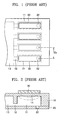
- A conventional piezoelectric inkjet printhead is illustrated in FIGS. 1 and 2. Referring to FIGS. 1 and 2, a
manifold 13, a plurality ofrestrictors 12 and a plurality ofink chambers 11, which constitute ink channels, are formed on achannel plate 10. A plurality ofnozzles 22 corresponding to the plurality ofink chambers 11 are formed on anozzle plate 20. Apiezoelectric actuator 30 is disposed on thechannel plate 10. Themanifold 13 is a path through which ink introduced from an ink reservoir (not shown) is supplied to the plurality ofink chambers 11. Therestrictors 12 are paths through which ink is introduced from themanifold 13 to the plurality ofink chambers 11. The plurality ofink chambers 11 in which ink to be ejected is contained are arranged on one side or both sides of themanifold 13. The plurality ofink chambers 11 whose volume is changed by the driving of thepiezoelectric actuator 30 produce a pressure change for ink ejection or introduction. To this end, portions forming upper walls of theink chambers 11 of thechannel plate 10 act asvibration plates 14 that are deformed by thepiezoelectric actuator 30. - In the operation of the conventional piezoelectric inkjet printhead constructed as above, if the
vibration plate 14 is deformed by the driving of thepiezoelectric actuator 30, the volume of theink chamber 11 is reduced, an internal pressure of theink chamber 11 is accordingly changed, and ink contained in theink chamber 11 is outwardly ejected through thenozzle 22. Subsequently, if thevibration plate 14 returns to its original state due to the driving of thepiezoelectric actuator 30, the volume of theink chamber 11 is increased, an internal pressure of theink chamber 11 is accordingly changed, and ink is introduced from themanifold 13 through therestrictor 12 to theink chamber 11. - When an image is printed using the conventional piezoelectric inkjet printhead having the above structure, the resolution of the image is greatly affected by the number of nozzles per inch. Here, the number of channels per inch (CPI) generally indicates the number of nozzles per inch, and the number of dots per inch (DPI) is generally a measure of the resolution of the image.
- In the conventional piezoelectric inkjet printhead illustrated in FIGS. 1 and 2, the volume of ink droplets ejected through the
nozzle 22 is greatly affected by the displacement of thevibration plate 14. That is, the greater displacement of thevibration plate 14, the greater ink droplets, and the less displacement of thevibration plate 14, the less ink droplets. The displacement of thevibration plate 14 is dependent on the area of thevibration plate 14, and the area of thevibration plate 14 is dependent on the volume of theink chamber 11. In the conventional inkjet printhead, if thevibration plate 14 is deformed by the driving of thepiezoelectric actuator 30, ink is ejected through thenozzle 22, and also flows back toward themanifold 13 via therestrictor 12. Accordingly, to eject ink droplets of uniform volume, the displacement of thevibration plate 14 should be greater in consideration of the amount of ink backflow, and accordingly, the area of thevibration plate 14 and the volume of theink chamber 11 should be greater. - Since the number of CPI of the piezoelectric inkjet printhead is in inverse proportion to a distance DN between
adjacent nozzles 22, to increase the number of CPI of the printhead, the distance DN between theadjacent nozzles 22 should be reduced. However, the conventional piezoelectric inkjet printhead having the aforesaid structure has limitations in reducing the distance DN between theadjacent nozzles 22 for the previously mentioned reasons. - In the meantime, the conventional inkjet printhead prints an image on a sheet of paper by reciprocating in a direction orthogonal to a feed direction of the sheet, that is, by reciprocating in a width direction of the sheet. Accordingly, the conventional inkjet printhead has a slow printing speed.
- Inkjet printheads having the same length as the width of a sheet of paper, which can increase a printing speed, have recently been developed, and an example of the inkjet printheads is disclosed in U.S. Patent No. 6,003,971. The disclosed printhead has a plurality of nozzles that are arrayed in a width direction of the sheet of paper to print an image on the sheet at high speed without reciprocation in the width direction of the sheet. The inkjet printhead having this structure is generally called a page-wide inkjet printhead.
- However, in order to print an image with sufficiently high resolution without any reciprocation in a width direction of a printing sheet of paper, the number of CPI needs to be equal to the number of DPI of an image. However, since the conventional piezoelectric inkjet printhead has structural limitations in increasing the number of CPI, it is difficult to have the same number of CPI as the number of DPI of the image.
- Accordingly, to satisfy the recent demands for an image with higher resolution, continuous efforts are needed to increase the number of CPI of a printhead.
- According to an aspect of the present invention, there is provided a piezoelectric inkjet printhead comprising: a plurality of pressure chambers containing ink to be ejected; a plurality of piezoelectric actuators providing a driving force for ink ejection to the plurality of pressure chambers; a manifold containing ink to be supplied to the plurality of pressure chambers; a plurality of restrictors supplying ink from the manifold to the plurality of pressure chambers; a plurality of nozzles ejecting ink from the plurality of pressure chambers; and a plurality of unidirectional shutters each installed at an outlet of each of the plurality of restrictors and adapted to open the restrictor when ink is supplied from the restrictor to the pressure chamber and close the restrictor and prevent backflow of ink when ink is ejected from the pressure chamber through the nozzle.
- The unidirectional shutter may be made of a thin plate and may be deflected due to a pressure change by the driving of the piezoelectric actuator. The unidirectional shutter may have a thickness of µms to tens of µms.
- The unidirectional shutter may have a shape to completely cover the outlet of the restrictor. The unidirectional shutter may have a rectangular shape corresponding to the outlet of the restrictor. The restrictor may have a width less than that of the pressure chamber, and the unidirectional shutter may have a width less than that of the pressure chamber and greater than that of the outlet of the restrictor. The unidirectional shutter may have a length greater than that of the outlet of the restrictor.
- The plurality of pressure chambers, the manifold, the plurality of restrictors, and the plurality of nozzles may be formed on a plurality of stacked channel plates, the plurality of unidirectional shutters are formed on a thin shutter plate, and the shutter plate may be disposed between, among the plurality of channel plates, a channel plate on which the plurality of pressure chambers are formed and a channel plate on which the plurality of restrictors are formed.
- Each of the plurality of channel plates may be a silicon substrate or a thin metal plate, and the shutter plate may be a thin metal plate. The thin metal plate may be a stainless steel sheet.
- The printhead may have a length corresponding to the width of a print medium, and the plurality of nozzles may be arrayed in a longitudinal direction of the printhead.
- The present invention thus provides a piezoelectric inkjet printhead, which can increase the number of channels per inch (CPI) by employing a unidirectional shutter that can prevent backflow of ink.
- The above and other features and advantages of the present invention will become more apparent by describing in detail exemplary embodiments thereof with reference to the attached drawings in which:
- FIG. 1 is a plan view of a conventional piezoelectric inkjet printhead;
- FIG. 2 is a sectional view of the conventional piezoelectric inkjet printhead shown in FIG. 1 taken along a longitudinal direction of a pressure chamber;
- FIG. 3 is a partial exploded perspective view of a piezoelectric inkjet printhead according to an embodiment of the present invention;
- FIG. 4 is a vertical sectional view of the inkjet printhead shown in FIG. 3;
- FIG. 5 is a schematic plan view for explaining relative volumes of a pressure chamber, a restrictor, and a unidirectional shutter;
- FIG. 6 is a plan view illustrating a nozzle arrangement in a piezoelectric inkjet printhead according to another embodiment of the present invention;
- FIG. 7 is a partial vertical sectional view of the inkjet printhead shown in FIG. 6; and
- FIGS. 8A and 8B are sectional views for explaining the operation of a unidirectional shutter in the inkjet printhead according to the present invention.
The present invention will now be described more fully with reference to the accompanying drawings, in which preferred embodiments of the invention are shown. In the drawings, the same elements are given the same reference numerals, and the size of components may be exaggerated for clarity of explanation. It will also be understood that when a layer is referred as being on another layer or a substrate, it can be directly on the other layer or the substrate, or intervening layers may also be present.
FIG. 3 is a partial exploded perspective view of a piezoelectric inkjet printhead according to an embodiment of the present invention. FIG. 4 is a vertical sectional view of the inkjet printhead shown in FIG. 3. FIG. 5 is a schematic plan view for explaining relative volumes of a pressure chamber, a restrictor, and a unidirectional shutter of the inkjet printhead shown in FIG. 3.
Referring to FIGS. 3 and 4, apiezoelectric inkjet printhead 100 comprises ink channels including a plurality ofpressure chambers 103, apiezoelectric actuator 130 providing a driving force for ink ejection to the plurality ofpressure chambers 103, and a plurality ofunidirectional shutters 122 installed inside the ink channels and preventing backflow of ink.
The ink channels include the plurality ofpressure chambers 103 containing ink to be ejected and producing a pressure change for ink ejection, amanifold 101 containing ink to be supplied to the plurality ofpressure chambers 103, a plurality ofrestrictors 102 supplying ink from themanifold 101 to the plurality ofpressure chambers 103, and a plurality ofnozzles 105 ejecting ink from the plurality ofpressure chambers 103. A plurality ofdampers 104 may be disposed between thepressure chambers 103 and thenozzles 105 to focus energy, which is generated in thepressure chambers 103 by thepiezoelectric actuators 130, on thenozzles 105 and damp a sharp pressure change.
Thepressure chambers 103, themanifold 101, therestrictors 102, thenozzles 105, and thedampers 104, which constitute the ink channels, are formed on a plurality of stackedchannel plates 111 through 113. For example, the plurality ofchannel plates 111 through 113 may include afirst channel plate 111, asecond channel plate 112, and athird channel plate 113 as shown in FIGS. 3 and 4.
In detail, the plurality ofpressure chambers 103 are formed to a predetermined depth in a lower portion of thefirst channel plate 111. The plurality ofpressure chambers 103 are parallel to one another, and each have a rectangular shape long in a direction of ink flow. Portions of thefirst channel plate 111, which form upper walls of thepressure chambers 103, act asvibration plates 107 that are deflected by the driving of thepiezoelectric actuator 130.
The manifold 101 is formed in thesecond channel plate 112. The manifold 101 may vertically pass through thesecond channel plate 112 as shown in FIGS. 3 and 4, or may be formed to a predetermined depth in an upper portion of thesecond channel plate 112. The plurality ofrestrictors 102 connecting the manifold 101 and one ends of the plurality ofpressure chambers 103 are formed in thesecond channel plate 112. Therestrictors 102 may be formed to a predetermined depth in the upper portion of thesecond channel plate 112 as shown in FIGS. 3 and 4. Further, thedampers 104 connecting thepressure chambers 103 and thenozzles 105 vertically pass through thesecond channel plate 112 at positions corresponding to the other ends of the plurality ofpressure chambers 103.
Thenozzles 105 pass through thethird channel plate 113 at positions corresponding to thedampers 104. Thenozzles 105 may have a taper shape with a decreasing section toward an outlet.
Each of the threechannel plates 111 through 113 constructed as above may be a silicon substrate. The ink channels may be formed in various ways by micro-processing a surface of the silicon substrate through a semiconductor process. However, the present invention is not limited thereto, but each of the threechannel plates 111 through 113 may be other substrate with good processibility.
In the meantime, the ink channel constituting elements separately formed in the threechannel plates 111 through 113 are just exemplified. That is, ink channels having various structures can be formed in theinkjet printhead 100 according to the present embodiment, and channel plates on which the ink channels are formed may be more or less than three.
Thepiezoelectric actuators 130 are formed on thefirst channel plate 111 in which thepressure chambers 103 are formed. Thepiezoelectric actuators 130 provide a driving force for ink ejection to thepressure chambers 103. Each of thepiezoelectric actuators 130 has a structure where a lower electrode acting as a common electrode, a piezoelectric layer deformed by applied voltage, and an upper electrode acting as a driving electrode are sequentially stacked on thefirst channel plate 111.
Each of the plurality ofunidirectional shutters 122, a feature of the present invention, is installed at an outlet of each of the plurality ofrestrictors 102. Theunidirectional shutter 122 opens the restrictor 102 when ink is supplied from the restrictor 102 to thepressure chamber 103, and closes therestrictor 102 and prevents backflow of ink when ink is ejected from thepressure chamber 103 through thenozzle 105. The operation of theunidirectional shutter 122 will be explained in detail later.
If backflow of ink is prevented by theunidirectional shutter 122, the area of thevibration plate 107 and the volume of thepressure chamber 103 needed to eject ink droplets of uniform volume can be reduced as compared to the area and volume of conventional ones. Accordingly, a distance betweenadjacent nozzles 105 can be reduced, and thus the number of channels per inch (CPI) of theprinthead 100 can be increased.
The plurality ofunidirectional shutters 122 are formed on athin shutter plate 120. Theshutter plate 120 is disposed between thefirst channel plate 111 on which the plurality ofpressure chambers 103 are formed and thesecond channel plate 112 on which the plurality ofrestrictors 102 are formed.
Theunidirectional shutter 122 functions by being deflected due to a pressure change in thepressure chamber 103 by the driving of thepiezoelectric actuator 130. Accordingly, it is preferable that theunidirectional shutter 122 be as thin as possible (e.g., µms to tens of µms) to be easily deflected unless a permanent deformation due to the pressure change occurs. Theunidirectional shutter 122 may be made of metal with predetermined elasticity, and preferably made of stainless steel with elasticity and ink corrosion-resistance.
Accordingly, theshutter plate 120 on which theunidirectional shutter 122 is formed may also be a thin metal plate, and preferably a stainless steel sheet.
It is preferable that theunidirectional shutter 122 have a shape and size to completely cover the outlet of therestrictor 102. This is because backflow of ink can be completely prevented.
In detail, as shown in FIG. 5, theunidirectional shutter 122 has a shape (e.g., a rectangular shape) corresponding to therestrictor 102.
The width WR of therestrictor 102 is less than the width WC of thepressure chamber 103. The width WS of theunidirectional shutter 122 is less than the width WC of the pressure chamber WC, such that theunidirectional shutter 122 can be freely deflected in thepressure chamber 104. Further, it is preferable that the width WS of theunidirectional shutter 122 be greater than the width WR of the outlet of therestrictor 102 and the length LS of theunidirectional shutter 122 be greater than the length LR of the outlet of therestrictor 102, so that theunidirectional shutter 122 can completely cover the outlet of therestrictor 102. Here, the outlet of therestrictor 102 is defined as a portion where therestrictor 102 and thepressure chamber 103 overlap.
FIG. 6 is a plan view illustrating a nozzle arrangement in a piezoelectric inkjet printhead according to another embodiment of the present invention. FIG. 7 is a partial vertical sectional view of the inkjet printhead shown in FIG. 6.
Referring to FIG. 6, the present invention can be applied to a page-wide inkjet printhead 200. The page-wide inkjet printhead 200 has a length corresponding to the width of a print medium, such as a printing sheet of paper. Here, the width of the printing sheet means is an extent in a direction orthogonal to a feed direction of the printing sheet. Theinkjet printhead 200 includes a plurality ofnozzles 205 that are arrayed in a longitudinal direction of theprinthead 200.
Referring to FIG. 7, the vertical section of theprinthead 200 is almost similar in structure to the vertical section of the inkjet printhead illustrated in FIG. 4. Accordingly, an explanation will be made focusing on the difference therebetween.
A manifold 201, a plurality ofrestrictors 202, a plurality ofpressure chambers 203, a plurality ofdampers 204, and a plurality ofnozzles 205, which constitute ink channels, are formed on six stackedchannel plates 211 through 216.
In detail, the plurality ofpressure chambers 203 pass through thefirst channel plate 211. Thesecond channel plate 212 is attached to a bottom surface of thefirst channel plate 211, and the plurality ofrestrictors 202 pass through thesecond channel plate 212. Upper portions of thedampers 204 are formed in thesecond channel plate 212. Thethird channel plate 213 is attached to a bottom surface of thesecond channel plate 212, and an upper portion of the manifold 201 and middle portions of thedampers 204 are formed in thethird channel plate 213. Thefourth channel plate 214 is attached to a bottom surface of thethird channel plate 213, and a lower portion of the manifold 201 and lower portions of thedampers 204 are formed in thefourth channel plate 214. Thefifth channel plate 215 is attached to a bottom surface of thefourth channel plate 214, and the plurality ofnozzles 205 pass through thefifth channel plate 215. Thesixth channel plate 216 covering thepressure chambers 203 is attached on a top surface of thefirst channel plate 211. Thesixth channel plate 216 acts as avibration plate 207. Accordingly,piezoelectric actuators 230 for deflecting thevibration plate 207 are formed on thesixth channel plate 216.
Each of the sixchannel plates 211 through 216 constructed as above may be a thin metal plate, and preferably a stainless steel sheet with ink corrosion-resistance, to maintain the strength of the page-wide inkjet printhead 200 with a relatively great length. In this case, the ink channels can be formed in various ways by etching, punching, or laser processing the stainless steel sheets. The stainless steel sheets may be attached to one another by brazing. However, the present invention is not limited thereto, but various well-known processing methods and attaching methods can be used.
Meanwhile, the ink channel constituting elements separately formed on the sixchannel plates 211 through 216 are just exemplified. That is, ink channels having various structures can be formed in theinkjet printhead 200, and channel plates on which the ink channels are formed may be more or less than six.
Each of a plurality ofunidirectional shutters 222, a feature of the present invention, installed at an outlet of each of the plurality ofrestrictors 202 to prevent backflow of ink is formed on athin shutter plate 220. Theshutter plate 220 is disposed between thefirst channel plate 211 on which the plurality ofpressure chambers 203 are formed and thesecond channel plate 212 on which the plurality ofrestrictors 202 are formed. The shape, size, and thickness of theunidirectional shutter 222 are the same as those described with reference to FIGS. 3 and 4. Theshutter plate 220 may be a thin metal plate, such as a stainless steel sheet, as described above.
As described above, the page-wide inkjet printhead 200 can be easily manufactured by stacking a plurality of stainless steel sheets, and a distance betweenadjacent nozzles 205 can be reduced by employing theunidirectional shutter 222 that can prevent backflow of ink. Accordingly, since the number of CPI of theinkjet printhead 200 can increase to be close or equal to the number of dots per inch (DPI) of an image, reciprocation in a width direction of a printing sheet of paper is minimized or is not required, thereby achieving a higher printing speed.
The operation of the unidirectional shutter in the inkjet printhead according to the present invention will now be explained with reference to FIGS. 4, 8A, and 8B. Since the operation of the unidirectional shutter is the same between the inkjet printhead illustrated in FIG. 4 and the inkjet printhead illustrated in FIG. 7, the operation of the unidirectional shutter will be explained on the basis of the inkjet printhead illustrated in FIG. 4.
Referring to FIG. 4, since there is no internal pressure change in thepressure chamber 103 if thepiezoelectric actuator 130 is not driven, theunidirectional shutter 122 is not deformed but is maintained at an even level.
Referring to FIG. 8A, if thepiezoelectric actuator 130 is driven for ink ejection, thevibration plate 107 under thepiezoelectric actuator 130 is deformed and the volume of thepressure chamber 103 is reduced. An internal pressure of thepressure chamber 103 is accordingly increased, and thus ink inside thepressure chamber 103 is outwardly ejected through thedamper 104 and thenozzle 105. At this time, theunidirectional shutter 122 is deflected downward due to the pressure rise in thepressure chamber 103 to close the outlet of therestrictor 102, thereby completely preventing backflow of ink from thepressure chamber 103 to therestrictor 102.
After ink ejection is made, as shown in FIG. 8B, if thevibration plate 107 returns to its original state, the volume of thepressure chamber 103 is increased. Accordingly, theunidirectional shutter 122 is deflected upward due to a pressure change in thepressure chamber 103 to open the outlet of therestrictor 102, thereby permitting ink stored in the manifold 101 to be introduced into thepressure chamber 103 through therestrictor 102.
As described above, since theunidirectional shutter 122 of theinkjet printhead 100 is deflected due to the pressure change in thepressure chamber 103 to close or open the outlet of therestrictor 102, backflow of ink can be prevented and smooth ink supply can be made.
As described above, since backflow of ink can be prevented by the unidirectional shutter, the area of the vibration plate and the volume of the pressure chamber needed to eject ink droplets of uniform volume can be reduced. Consequently, the piezoelectric inkjet printhead can have a greater number of CPI than that of the conventional inkjet printhead.
The page-wide inkjet printhead with a higher printing speed can be easily realized, and the page-wide inkjet printhead can be easily manufactured by stacking a plurality of stainless steel sheets.
While the present invention has been particularly shown and described with reference to exemplary embodiments thereof, it will be understood by those of ordinary skill in the art that various changes in form and details may be made therein without departing from the scope of the present invention as defined by the following claims.
Claims (12)
- A piezoelectric inkjet printhead comprising:a plurality of pressure chambers containing ink to be ejected;a plurality of piezoelectric actuators for providing a driving force for ink ejection to the plurality of pressure chambers;a manifold containing ink to be supplied to the plurality of pressure chambers;a plurality of restrictors for supplying ink from the manifold to the plurality of pressure chambers;a plurality of nozzles for ejecting ink from the plurality of pressure chambers; anda plurality of unidirectional shutters each installed at an outlet of each of the plurality of restrictors and adapted to open the restrictor when ink is supplied from the restrictor to the pressure chamber and close the restrictor and prevent backflow of ink when ink is ejected from the pressure chamber through the nozzle.
- The piezoelectric inkjet printhead of claim 1, wherein the unidirectional shutter is made of a thin plate and is deflected due to a pressure change by the driving of the piezoelectric actuator.
- The piezoelectric inkjet printhead of claim 1 or 2, wherein the unidirectional shutter has a thickness of µms to tens of µms.
- The piezoelectric inkjet printhead of any preceding claim, wherein the unidirectional shutter has a shape to completely cover the outlet of the restrictor.
- The piezoelectric inkjet printhead of claim 4, wherein the unidirectional shutter has a rectangular shape corresponding to the outlet of the restrictor.
- The piezoelectric inkjet printhead of claim 4 or 5, wherein the restrictor has a width less than that of the pressure chamber, and the unidirectional shutter has a width less than that of the pressure chamber and greater than that of the outlet of the restrictor.
- The piezoelectric inkjet printhead of any of claims 4 to 6, wherein the unidirectional shutter has a length greater than that of the outlet of the restrictor.
- The piezoelectric inkjet printhead of any preceding claim, wherein the plurality of pressure chambers, the manifold, the plurality of restrictors, and the plurality of nozzles are formed on a plurality of stacked channel plates, the plurality of unidirectional shutters are formed on a thin shutter plate, and the shutter plate is disposed between, among the plurality of channel plates, a channel plate on which the plurality of pressure chambers are formed and a channel plate on which the plurality of restrictors are formed.
- The piezoelectric inkjet printhead of claim 8, wherein each of the plurality of channel plates is a silicon substrate, and the shutter plate is a thin metal plate.
- The piezoelectric inkjet printhead of claim 8, wherein the shutter plate and each of the plurality of channel plates are thin metal plates.
- The piezoelectric inkjet printhead of claim 9 or 10, wherein the thin metal plate is a stainless steel sheet.
- The piezoelectric inkjet printhead of any preceding claim, wherein the printhead has a length corresponding to the width of a print medium, and the plurality of nozzles are arrayed in a longitudinal direction of the printhead.
Applications Claiming Priority (1)
| Application Number | Priority Date | Filing Date | Title |
|---|---|---|---|
| KR1020040089212A KR100624443B1 (en) | 2004-11-04 | 2004-11-04 | Piezoelectric inkjet printhead with one-way shutter |
Publications (3)
| Publication Number | Publication Date |
|---|---|
| EP1655136A2 true EP1655136A2 (en) | 2006-05-10 |
| EP1655136A3 EP1655136A3 (en) | 2008-03-19 |
| EP1655136B1 EP1655136B1 (en) | 2010-09-08 |
Family
ID=35695881
Family Applications (1)
| Application Number | Title | Priority Date | Filing Date |
|---|---|---|---|
| EP05252762A Expired - Lifetime EP1655136B1 (en) | 2004-11-04 | 2005-05-05 | Piezoelectric inkjet printhead having unidirectional shutter |
Country Status (5)
| Country | Link |
|---|---|
| US (1) | US7549737B2 (en) |
| EP (1) | EP1655136B1 (en) |
| JP (1) | JP4727382B2 (en) |
| KR (1) | KR100624443B1 (en) |
| DE (1) | DE602005023400D1 (en) |
Cited By (2)
| Publication number | Priority date | Publication date | Assignee | Title |
|---|---|---|---|---|
| EP1862311A1 (en) * | 2006-05-30 | 2007-12-05 | Mimaki Engineering Co., Ltd. | Fluid ejection apparatus and fluid ejection apparatus assembly |
| CN109835065A (en) * | 2017-11-28 | 2019-06-04 | 精工爱普生株式会社 | Liquid ejection apparatus |
Families Citing this family (17)
| Publication number | Priority date | Publication date | Assignee | Title |
|---|---|---|---|---|
| CN101377192B (en) * | 2007-08-30 | 2012-06-13 | 研能科技股份有限公司 | Fluid delivery device |
| KR100974950B1 (en) * | 2008-09-17 | 2010-08-10 | 삼성전기주식회사 | Diagonal printing method using inkjet device |
| KR20110062778A (en) * | 2009-12-04 | 2011-06-10 | 삼성전기주식회사 | Inkjet head |
| EP2605910B1 (en) * | 2010-08-19 | 2020-10-21 | Hewlett-Packard Development Company, L.P. | Wide-array inkjet printhead assembly with a shroud |
| JP6417740B2 (en) * | 2014-06-18 | 2018-11-07 | セイコーエプソン株式会社 | Liquid ejecting head and manufacturing method of liquid ejecting head |
| JP2016049680A (en) * | 2014-08-29 | 2016-04-11 | キヤノン株式会社 | Element substrate and liquid discharge head |
| EP3233496A4 (en) * | 2015-04-27 | 2018-09-19 | Hewlett-Packard Development Company, L.P. | Printhead with printer fluid check valve |
| JP6992326B2 (en) * | 2017-08-29 | 2022-01-13 | セイコーエプソン株式会社 | Liquid discharge device |
| JP6954056B2 (en) * | 2017-11-30 | 2021-10-27 | セイコーエプソン株式会社 | Liquid injection device |
| CN109980084B (en) * | 2019-04-09 | 2020-12-01 | 京东方科技集团股份有限公司 | Inkjet printheads and inkjet printing equipment |
| CN114106588B (en) * | 2020-08-25 | 2023-01-03 | 上海迪赢生物科技有限公司 | Functionalized surface treatment method for high-flux nucleic acid in-situ synthesis by 3D ink-jet method |
| JP7673480B2 (en) * | 2021-04-30 | 2025-05-09 | セイコーエプソン株式会社 | LIQUID EJECTION HEAD AND LIQUID EJECTION APPARATUS |
| US12391052B2 (en) * | 2023-02-16 | 2025-08-19 | Ricoh Company, Ltd. | Passive mixer in jetting channels of a printhead |
| US12358301B2 (en) * | 2023-02-16 | 2025-07-15 | Ricoh Company Ltd. | Active mixer in jetting channels of a printhead |
| US12533882B2 (en) | 2023-02-16 | 2026-01-27 | Ricoh Company, Ltd. | Fluid mixers in jetting channels of a printhead |
| US12291032B2 (en) | 2023-02-16 | 2025-05-06 | Ricoh Company, Ltd. | Flow-through printhead |
| CN116494647A (en) * | 2023-04-10 | 2023-07-28 | 北京大学 | Inkjet printing device and piezoelectric inkjet printer |
Family Cites Families (19)
| Publication number | Priority date | Publication date | Assignee | Title |
|---|---|---|---|---|
| DE2905063A1 (en) * | 1979-02-10 | 1980-08-14 | Olympia Werke Ag | Ink nozzle air intake avoidance system - has vibratory pressure generator shutting bore in membrane in rest position |
| JPS61175045A (en) * | 1985-01-31 | 1986-08-06 | Nec Home Electronics Ltd | Ink jet head |
| JPH01133752A (en) * | 1987-11-19 | 1989-05-25 | Ricoh Co Ltd | inkjet recording head |
| JPH01235648A (en) * | 1988-03-16 | 1989-09-20 | Seiko Epson Corp | Ink jet head |
| JPH02253962A (en) * | 1989-03-29 | 1990-10-12 | Ricoh Co Ltd | Ink jet recording apparatus |
| JPH0671881A (en) * | 1992-08-07 | 1994-03-15 | Sony Corp | Inkjet printhead and inkjet printer |
| CH688960A5 (en) * | 1994-11-24 | 1998-06-30 | Pelikan Produktions Ag | Droplet generator for microdroplets, especially for an inkjet printer. |
| US6003971A (en) | 1996-03-06 | 1999-12-21 | Tektronix, Inc. | High-performance ink jet print head having an improved ink feed system |
| US5872582A (en) * | 1996-07-02 | 1999-02-16 | Hewlett-Packard Company | Microfluid valve for modulating fluid flow within an ink-jet printer |
| US6264849B1 (en) * | 1997-07-15 | 2001-07-24 | Silverbrook Research Pty Ltd | Method of manufacture of a bend actuator direct ink supply ink jet printer |
| CN1160194C (en) * | 1998-07-28 | 2004-08-04 | 佳能株式会社 | Liquid ejection head, liquid ejection method, and liquid ejection device |
| JP3241334B2 (en) * | 1998-11-16 | 2001-12-25 | 松下電器産業株式会社 | Ink jet head and method of manufacturing the same |
| JP2000246896A (en) | 1999-03-02 | 2000-09-12 | Seiko Epson Corp | Ink jet recording head and ink jet recording apparatus |
| JP2001018385A (en) * | 1999-07-09 | 2001-01-23 | Ricoh Co Ltd | Inkjet head |
| US6431689B1 (en) * | 2000-11-28 | 2002-08-13 | Xerox Corporation | Structures including microvalves and methods of forming structures |
| JP3951119B2 (en) * | 2002-06-26 | 2007-08-01 | ブラザー工業株式会社 | Inkjet printer head |
| JP4678135B2 (en) * | 2003-06-17 | 2011-04-27 | セイコーエプソン株式会社 | pump |
| JP4075731B2 (en) * | 2003-08-14 | 2008-04-16 | ブラザー工業株式会社 | Inkjet head |
| KR20060039111A (en) * | 2004-11-02 | 2006-05-08 | 삼성전자주식회사 | Inkjet Printheads with Cantilever Actuators |
-
2004
- 2004-11-04 KR KR1020040089212A patent/KR100624443B1/en not_active Expired - Fee Related
-
2005
- 2005-05-05 EP EP05252762A patent/EP1655136B1/en not_active Expired - Lifetime
- 2005-05-05 DE DE602005023400T patent/DE602005023400D1/en not_active Expired - Lifetime
- 2005-09-30 US US11/239,104 patent/US7549737B2/en not_active Expired - Fee Related
- 2005-10-25 JP JP2005310376A patent/JP4727382B2/en not_active Expired - Fee Related
Cited By (4)
| Publication number | Priority date | Publication date | Assignee | Title |
|---|---|---|---|---|
| EP1862311A1 (en) * | 2006-05-30 | 2007-12-05 | Mimaki Engineering Co., Ltd. | Fluid ejection apparatus and fluid ejection apparatus assembly |
| CN101659153B (en) * | 2006-05-30 | 2011-10-05 | 株式会社御牧工程 | Fluid ejection apparatus and fluid ejection apparatus assembly |
| CN109835065A (en) * | 2017-11-28 | 2019-06-04 | 精工爱普生株式会社 | Liquid ejection apparatus |
| CN109835065B (en) * | 2017-11-28 | 2020-12-08 | 精工爱普生株式会社 | Liquid ejection device |
Also Published As
| Publication number | Publication date |
|---|---|
| JP4727382B2 (en) | 2011-07-20 |
| US20060092236A1 (en) | 2006-05-04 |
| US7549737B2 (en) | 2009-06-23 |
| DE602005023400D1 (en) | 2010-10-21 |
| KR20060040030A (en) | 2006-05-10 |
| JP2006130916A (en) | 2006-05-25 |
| KR100624443B1 (en) | 2006-09-15 |
| EP1655136B1 (en) | 2010-09-08 |
| EP1655136A3 (en) | 2008-03-19 |
Similar Documents
| Publication | Publication Date | Title |
|---|---|---|
| EP1652672B1 (en) | Inkjet printhead having cantilever actuator | |
| EP1655136B1 (en) | Piezoelectric inkjet printhead having unidirectional shutter | |
| EP1652673B1 (en) | Nozzle plate unit, inkjet printhead with the same and method of manifacturing the same | |
| EP1652674B1 (en) | Nozzle plate unit, inkjet print head with the same and method of manufacturing the same | |
| US8042919B2 (en) | Piezoelectric inkjet printhead | |
| CN100393516C (en) | Inkjet head of inkjet printer | |
| EP0773108A2 (en) | Ink jet type recording head | |
| JP4269601B2 (en) | Droplet discharge head and droplet discharge apparatus | |
| JP7419487B1 (en) | Head chip, liquid jet head and liquid jet recording device | |
| CN1328050C (en) | Liquid discharging head and liquid discharging device | |
| JP4324757B2 (en) | Inkjet printer head | |
| JP4453965B2 (en) | Ink jet recording head and recording apparatus | |
| JP2011167881A (en) | Liquid ejection head and liquid ejection apparatus | |
| EP2342081B1 (en) | Electrostatic liquid-ejection actuation mechanism | |
| JP3125536B2 (en) | Inkjet head | |
| JP2005081545A (en) | Inkjet printer head | |
| EP0987111A2 (en) | Actuator unit | |
| JP4137681B2 (en) | Liquid discharge head, liquid discharge head cartridge, liquid discharge apparatus, and ink jet recording apparatus | |
| JP2003094644A (en) | Ink jet head and ink jet recording apparatus | |
| KR20070079296A (en) | Piezoelectric inkjet printheads | |
| JP2001162791A (en) | Ink jet recording head | |
| JP2005125696A (en) | Inkjet recording head | |
| JP2007168108A (en) | Liquid discharge head and apparatus | |
| JP2009126076A (en) | Liquid ejecting head and liquid ejecting apparatus | |
| JP2006264048A (en) | Liquid discharge head and liquid discharge apparatus |
Legal Events
| Date | Code | Title | Description |
|---|---|---|---|
| PUAI | Public reference made under article 153(3) epc to a published international application that has entered the european phase |
Free format text: ORIGINAL CODE: 0009012 |
|
| AK | Designated contracting states |
Kind code of ref document: A2 Designated state(s): AT BE BG CH CY CZ DE DK EE ES FI FR GB GR HU IE IS IT LI LT LU MC NL PL PT RO SE SI SK TR |
|
| AX | Request for extension of the european patent |
Extension state: AL BA HR LV MK YU |
|
| PUAL | Search report despatched |
Free format text: ORIGINAL CODE: 0009013 |
|
| AK | Designated contracting states |
Kind code of ref document: A3 Designated state(s): AT BE BG CH CY CZ DE DK EE ES FI FR GB GR HU IE IS IT LI LT LU MC NL PL PT RO SE SI SK TR |
|
| AX | Request for extension of the european patent |
Extension state: AL BA HR LV MK YU |
|
| 17P | Request for examination filed |
Effective date: 20080716 |
|
| AKX | Designation fees paid |
Designated state(s): DE FR GB |
|
| 17Q | First examination report despatched |
Effective date: 20090507 |
|
| GRAP | Despatch of communication of intention to grant a patent |
Free format text: ORIGINAL CODE: EPIDOSNIGR1 |
|
| RAP1 | Party data changed (applicant data changed or rights of an application transferred) |
Owner name: SAMSUNG ELECTRO-MECHANICS CO., LTD. |
|
| GRAS | Grant fee paid |
Free format text: ORIGINAL CODE: EPIDOSNIGR3 |
|
| GRAA | (expected) grant |
Free format text: ORIGINAL CODE: 0009210 |
|
| AK | Designated contracting states |
Kind code of ref document: B1 Designated state(s): DE FR GB |
|
| REG | Reference to a national code |
Ref country code: GB Ref legal event code: FG4D |
|
| REF | Corresponds to: |
Ref document number: 602005023400 Country of ref document: DE Date of ref document: 20101021 Kind code of ref document: P |
|
| PLBE | No opposition filed within time limit |
Free format text: ORIGINAL CODE: 0009261 |
|
| STAA | Information on the status of an ep patent application or granted ep patent |
Free format text: STATUS: NO OPPOSITION FILED WITHIN TIME LIMIT |
|
| 26N | No opposition filed |
Effective date: 20110609 |
|
| REG | Reference to a national code |
Ref country code: DE Ref legal event code: R097 Ref document number: 602005023400 Country of ref document: DE Effective date: 20110609 |
|
| PGFP | Annual fee paid to national office [announced via postgrant information from national office to epo] |
Ref country code: FR Payment date: 20130408 Year of fee payment: 9 Ref country code: GB Payment date: 20130326 Year of fee payment: 9 |
|
| PGFP | Annual fee paid to national office [announced via postgrant information from national office to epo] |
Ref country code: DE Payment date: 20130315 Year of fee payment: 9 |
|
| REG | Reference to a national code |
Ref country code: DE Ref legal event code: R119 Ref document number: 602005023400 Country of ref document: DE |
|
| GBPC | Gb: european patent ceased through non-payment of renewal fee |
Effective date: 20140505 |
|
| REG | Reference to a national code |
Ref country code: FR Ref legal event code: ST Effective date: 20150130 |
|
| REG | Reference to a national code |
Ref country code: DE Ref legal event code: R119 Ref document number: 602005023400 Country of ref document: DE Effective date: 20141202 |
|
| PG25 | Lapsed in a contracting state [announced via postgrant information from national office to epo] |
Ref country code: DE Free format text: LAPSE BECAUSE OF NON-PAYMENT OF DUE FEES Effective date: 20141202 |
|
| PG25 | Lapsed in a contracting state [announced via postgrant information from national office to epo] |
Ref country code: GB Free format text: LAPSE BECAUSE OF NON-PAYMENT OF DUE FEES Effective date: 20140505 Ref country code: FR Free format text: LAPSE BECAUSE OF NON-PAYMENT OF DUE FEES Effective date: 20140602 |