EP1655006B1 - Process for testing of peel strength of fasteners - Google Patents
Process for testing of peel strength of fasteners Download PDFInfo
- Publication number
- EP1655006B1 EP1655006B1 EP05023472A EP05023472A EP1655006B1 EP 1655006 B1 EP1655006 B1 EP 1655006B1 EP 05023472 A EP05023472 A EP 05023472A EP 05023472 A EP05023472 A EP 05023472A EP 1655006 B1 EP1655006 B1 EP 1655006B1
- Authority
- EP
- European Patent Office
- Prior art keywords
- curved surface
- portions
- over
- test
- closure system
- Prior art date
- Legal status (The legal status is an assumption and is not a legal conclusion. Google has not performed a legal analysis and makes no representation as to the accuracy of the status listed.)
- Not-in-force
Links
Images


Classifications
-
- A—HUMAN NECESSITIES
- A61—MEDICAL OR VETERINARY SCIENCE; HYGIENE
- A61F—FILTERS IMPLANTABLE INTO BLOOD VESSELS; PROSTHESES; DEVICES PROVIDING PATENCY TO, OR PREVENTING COLLAPSING OF, TUBULAR STRUCTURES OF THE BODY, e.g. STENTS; ORTHOPAEDIC, NURSING OR CONTRACEPTIVE DEVICES; FOMENTATION; TREATMENT OR PROTECTION OF EYES OR EARS; BANDAGES, DRESSINGS OR ABSORBENT PADS; FIRST-AID KITS
- A61F13/00—Bandages or dressings; Absorbent pads
- A61F13/15—Absorbent pads, e.g. sanitary towels, swabs or tampons for external or internal application to the body; Supporting or fastening means therefor; Tampon applicators
- A61F13/84—Accessories, not otherwise provided for, for absorbent pads
Definitions
- the invention relates to a method for testing the closure forces of a sheared closure system on absorbent personal care articles such as diapers, belted diapers, incontinence diapers and napkins, by performing a tensile test and determining the tensile forces involved, said closure system comprising two planar sections which are overlaid in order to work together in an adhesive, in particular adhesive or mechanically adhesive manner.
- Absorbent hygiene articles of the aforementioned type are usually equipped with adhesive or mechanically acting closure means which form a releasable closure system, by means of which the hygiene article in a proper position and on the individual body shape of the user, especially adapted to his hip circumference, can be created.
- the closure system is opened and possibly closed again in the former case.
- closure means for forming the closure systems are typically adhesive coated tabs which are adhesively applied to appropriately formed landing zones to close the article, or are mechanically acting closure means comprising a hook forming closure component and a loop forming closure component have, which can cooperate mechanically adhesive.
- closure system In the formation of closure systems for hygiene articles, on the one hand, a stable closure connection is to be achieved, which also takes into account movement situations and which does not unintentionally release. On the other hand, however, the closure system should be able to be opened non-destructively, if desired, and preferably also be resealable.
- peel angle 180 °
- the object of the present invention is to better adapt the test conditions on which it is based to actual carrying situations, in order to increase the accuracy of the results achieved here and their meaningfulness.
- the curved surface is intended to simulate a hip or abdominal area of a user.
- the test conditions are further adapted to an actual wearing situation in the use of the hygiene article.
- the pressure exerted by a user's abdomen or hips and the support of the closure system, which is usually in the abdomen or hip area has an effect on the closure forces.
- the curved surface is at least partially curved in a circular arc, wherein the radius of the arc can be variable but in particular constant.
- the arcuately curved surface at least in sections has a radius of curvature of 200-600 mm, in particular of 250-550 mm, in particular of 300-500 mm and more particularly of 350-450 mm.
- planar sections For carrying out the tensile test, it proves to be advantageous if the planar sections directly be formed out of a flat material forming them, in particular punched out. It would be conceivable that this flat material is connected as a whole with terminals of a Switzerlandprüfvorraum and claimed to train. However, it proves to be advantageous if the planar sections are connected to a flexible substrate and placed together with this over the arcuate curved surface.
- the areal sections are preferably lengthened by the flexible substrate, so that they protrude in particular, comparable to a belt buckle, over one end of the flexible substrate and cooperate with one another releasably in this projecting area.
- the present invention also relates to a device for carrying out the method, which is characterized by a in the direction of the tensile forces to be applied curved surface against which the closure system to be tested can be applied when it is claimed by a preferably motor-driven device to train
- a tensile tester type Z010 / TN 2S, load cell 100 N available from Zwick GmbH & Co KG, Ulm, Germany, with a jaw width for clamping the test piece of 60 mm can be used.
- the closure system to be tested with a loop-forming component and a hook-forming component adhering thereto is placed over a curved surface which is intended to simulate a rounding of the abdominal area of a user.
- a flexible substrate for example a one-sided adhesive tape of a preferred width of 25 mm, available under the name STA 306 from 3M Kunststoff GmbH based in Neuss, is used.
- the tape is made of polypropylene, its surface is coated by a urethane-modified silicone polymer.
- the basis weight of the pressure-sensitive adhesive application is 23 g / m 2 .
- the test specimen placed over the curved surface, consisting of adhering planar sections of the closure means, is made by using the tensile tester claimed to train, resulting in a shearing stress on the adhering planar sections.
- the mechanical closure means 1 to be used that is to say the loop-forming nonwoven material 2 and a hook-forming component 3 of the closure system, are conditioned for 24 h at 23 ° C. and 50% relative atmospheric humidity.
- Areal sections 6 of a size of 50 x 300 mm are punched out of the loop-forming nonwoven material 2 and sandwiched between the ends 8 of two single-sided adhesive tapes 10 of width 25 mm, which are glued together, so that there is a projection of the nonwoven material 2 of 50 x 250 mm. If the available material has a smaller dimension from the outset, it is fastened to the substrate 10 in such a way that a protrusion results which allows a 25 ⁇ 20 mm overlap with the hook-forming component 3 of the closure means 1.
- an areal section 12 of 25 ⁇ 20 mm is punched out of the hook-forming component 3 of the closure means 1 and, as shown in FIGS. 1 and 3, fixed by two adhesive tapes 14 glued together with their adhesive surfaces in such a way that the upper adhesive tape covers the rear side of the planar section 12 overlaps and the lower tape is flush with the planar portion 12 adjacent.
- the sheet-like portion 12 of the hook-forming component 3 (25 x 20 mm) is now on the section 6 of
- the spacing of the hook-forming component 3 from the longitudinal end edge of the nonwoven material 2 is 10 mm and from the lateral longitudinal edges 12.5 mm in each case (see Figure 1).
- the superimposed planar sections 6, 12 are connected to each other by rolling four times with a 50 mm wide and 100 mm in diameter roll with a smooth surface and a roll weight of 5 kg, wherein the winding speed is 20-100 mm / sec.
- the loop-forming nonwoven material 2 elongated as described above is centered centered in the lower jaw 20 of the tensile tester 22, and the opposite end of the hook-forming component 3 elongated as described above is also centered in the movable upper jaw 24 of the tensile tester 22.
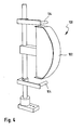
- the specimen clamped in this way is placed over the device 100 shown in FIGS. 2 and 4, which is intended to simulate the abdominal region of a user.
- This device 100 is shown in perspective in FIG.
- One recognizes an arcuately curved surface 102 made of polished steel with a surface roughness of 5 to 25 microns and with a radius of curvature R of at least partially 400 mm and a chord length SL of 300 mm.
- test speed 300 mm / min - Clamping length of the specimen: 430 mm (see Figure 2) - Measuring path: Distance to the replacement of VerMedicstoffkomponen th of each other - pre-load: 0.2N - test number: n ⁇ 6.
- the evaluation is carried out in such a way that the maximum force determined until the closing of the closure means is rounded down to two decimal places in N (Newton) and is given in the form of an average value of the n measurements and the standard deviation and a minimum value and a maximum value.
- a hook-forming component which can be used together with a loop-forming component of a mechanical closure means is, for example, under the trade name "Microplast” 42-288-HX200-PP3 from G. Binder GmbH & Co. KG Textil and Kunststofftechnik, Holzgerlingen, Germany.
- the hooks have a mushroom shape with approximately hexagonal area of the head. There are about 288 such mushroom-shaped protrusions per cm 2 .
- the material is made of polypropylene and has a thickness of about 0.42 mm. It was made by extrusion. The height of the mushroom-shaped elevation opposite the bottom of the material is about 0.26 mm. The distance between the edges of the heads is approx. 200 ⁇ m.
Landscapes
- Health & Medical Sciences (AREA)
- Epidemiology (AREA)
- Engineering & Computer Science (AREA)
- Biomedical Technology (AREA)
- Heart & Thoracic Surgery (AREA)
- Vascular Medicine (AREA)
- Life Sciences & Earth Sciences (AREA)
- Animal Behavior & Ethology (AREA)
- General Health & Medical Sciences (AREA)
- Public Health (AREA)
- Veterinary Medicine (AREA)
- Absorbent Articles And Supports Therefor (AREA)
- Investigating Strength Of Materials By Application Of Mechanical Stress (AREA)
Abstract
Description
Die Erfindung betrifft ein Verfahren zum Prüfen der Verschlusskräfte eines auf Scherung beanspruchten Verschlusssystems bei absorbierenden Hygieneartikeln, wie Windeln, Gürtelwindeln, Inkontinenzwindeln und -vorlagen, durch Ausführen einer Zugprüfung und Bestimmen der hierbei auftretenden Zugkräfte, wobei das Verschlusssystem zwei flächenhafte Abschnitte umfasst, die aufeinandergelegt werden, um haftend, insbesondere klebend haftend oder mechanisch haftend, zusammenzuwirken.The invention relates to a method for testing the closure forces of a sheared closure system on absorbent personal care articles such as diapers, belted diapers, incontinence diapers and napkins, by performing a tensile test and determining the tensile forces involved, said closure system comprising two planar sections which are overlaid in order to work together in an adhesive, in particular adhesive or mechanically adhesive manner.
Absorbierende Hygieneartikel der vorstehend genannten Art werden üblicherweise mit klebenden oder mechanisch wirkenden Verschlussmitteln ausgestattet, die ein lösbares Verschlusssystem bilden, mittels dessen der Hygieneartikel in einer bestimmungsgemäßen Position und an die individuelle Körpergestalt des Benutzers, insbesondere an seinen Hüftumfang angepasst, angelegt werden kann. Zur Prüfung des Gebrauchszustands des Hygieneartikels oder zum Wechseln des als benutzt erkannten Hygieneartikels wird das Verschlusssystem geöffnet und im ersteren Fall gegebenenfalls wieder geschlossen.Absorbent hygiene articles of the aforementioned type are usually equipped with adhesive or mechanically acting closure means which form a releasable closure system, by means of which the hygiene article in a proper position and on the individual body shape of the user, especially adapted to his hip circumference, can be created. To check the state of use of the hygiene article or to change the recognized as used sanitary article, the closure system is opened and possibly closed again in the former case.
Bei den Verschlussmitteln zur Bildung der Verschlusssysteme handelt es sich in der Regel um mit Kleber beschichtete Laschen, die auf entsprechend ausgebildete Landezonen zum Schließen des Artikels klebend haftend aufgebracht werden, oder es handelt sich um mechanisch wirkende Verschlussmittel, die eine hakenbildende Verschlusskomponente und eine schlaufenbildende Verschlusskomponente aufweisen, die mechanisch haftend zusammenwirken können.The closure means for forming the closure systems are typically adhesive coated tabs which are adhesively applied to appropriately formed landing zones to close the article, or are mechanically acting closure means comprising a hook forming closure component and a loop forming closure component have, which can cooperate mechanically adhesive.
Bei der Ausbildung von Verschlusssystemen für Hygieneartikel soll einerseits eine stabile Verschlussverbindung erreicht werden, die auch Bewegungssituationen Rechnung trägt und die sich nicht ungewollt löst. Andererseits soll aber das Verschlusssystem zerstörungsfrei geöffnet werden können, wenn dies erwünscht ist, und vorzugsweise auch wiederverschließbar sein. Um die Kräfte bei Tragesituationen zu simulieren, also insbesondere in Hüftumfangsrichtung wirkende Zugkräfte, die auf die Verschlusssysteme einwirken, ist es bekannt, bei solchen Verschlusssystemen Zugprüfversuche durchzuführen, bei denen das Verschlusssystem entweder auf Abschälung ("peeling", Abzugswinkel = 180°) oder auf Scherung beansprucht wird. Es werden die Kräfte während der Ausführung einer Zugprüfung bis hin zum Lösen der Verschlussverbindung aufgezeichnet.In the formation of closure systems for hygiene articles, on the one hand, a stable closure connection is to be achieved, which also takes into account movement situations and which does not unintentionally release. On the other hand, however, the closure system should be able to be opened non-destructively, if desired, and preferably also be resealable. In order to simulate the forces in carrying situations, ie tensile forces acting on the closure systems in particular in the direction of the hip, it is known to carry out tensile tests in such closure systems in which the closure system is either peeling (peel angle = 180 °) or Shear is claimed. The forces are recorded during the execution of a tensile test up to the release of the sealing connection.
Der vorliegenden Erfindung liegt die Aufgabe zugrunde, die hierbei zugrundegelegten Prüfbedingungen besser an tatsächliche Tragesituationen anzupassen, um die Genauigkeit der hierbei erzielten Ergebnisse und deren Aussagegehalt zu erhöhen.The object of the present invention is to better adapt the test conditions on which it is based to actual carrying situations, in order to increase the accuracy of the results achieved here and their meaningfulness.
Diese Aufgabe wird bei einem Verfahren der eingangs genannten Art erfindungsgemäß dadurch gelöst, dass die zwei flächenhaften Abschnitte für die Durchführung der Zugprüfung über eine gekrümmte Fläche gelegt werden und dabei auf Zug beansprucht werden.This object is achieved in a method of the type mentioned in the present invention, that the two planar sections are placed on a curved surface for the performance of the tensile test and thereby claimed to train.
Die gekrümmte Fläche soll dabei einen Hüft- oder Bauchbereich eines Benutzers simulieren. Auf diese Weise werden die Prüfbedingungen weiter an eine tatsächliche Tragesituation im Gebrauch des Hygieneartikels angepasst. Es zeigt sich nämlich, dass der vom Bauch oder den Hüften eines Benutzers ausgehende Druck und die Stützung des Verschlusssystems, welche sich üblicherweise im Bauch oder Hüftbereichbereich befindet, eine Auswirkung auf die Verschlusskräfte ausübt.The curved surface is intended to simulate a hip or abdominal area of a user. In this way, the test conditions are further adapted to an actual wearing situation in the use of the hygiene article. In fact, it turns out that the pressure exerted by a user's abdomen or hips and the support of the closure system, which is usually in the abdomen or hip area, has an effect on the closure forces.
Vorteilhaft ist die gekrümmte Fläche wenigstens abschnittsweise kreisbogenförmig gekrümmt, wobei der Radius des Kreisbogens veränderlich insbesondere aber konstant sein kann.Advantageously, the curved surface is at least partially curved in a circular arc, wherein the radius of the arc can be variable but in particular constant.
Es hat sich als zweckmäßig erwiesen, wenn die bogenförmig gekrümmte Fläche wenigstens abschnittsweise einen Krümmungsradius von 200 - 600 mm, insbesondere von 250 - 550 mm, insbesondere von 300 - 500 mm und weiter insbesondere von 350 - 450 mm aufweist.It has proved to be expedient if the arcuately curved surface at least in sections has a radius of curvature of 200-600 mm, in particular of 250-550 mm, in particular of 300-500 mm and more particularly of 350-450 mm.
Für die Durchführung des Zugprüfversuchs erweist es sich als vorteilhaft, wenn die flächenhaften Abschnitte direkt aus einem sie bildenden Flachmaterial herausgebildet, insbesondere herausgestanzt werden. Es wäre denkbar, dass dieses Flachmaterial als Ganzes mit Klemmen einer Zugprüfvorrichtung verbunden und auf Zug beansprucht wird. Indessen erweist es sich als vorteilhaft, wenn die flächenhaften Abschnitte mit einem biegsamen Substrat verbunden werden und zusammen mit diesem über die bogenförmig gekrümmte Fläche gelegt werden. Die flächenhaften Abschnitte werden dabei durch das biegsame Substrat vorzugsweise verlängert, so dass sie insbesondere, vergleichbar einer Gürtelschnalle, über ein Ende des biegsamen Substrats vorstehen und in diesem vorstehenden Bereich miteinander lösbar haftend zusammenwirken.For carrying out the tensile test, it proves to be advantageous if the planar sections directly be formed out of a flat material forming them, in particular punched out. It would be conceivable that this flat material is connected as a whole with terminals of a Zugprüfvorrichtung and claimed to train. However, it proves to be advantageous if the planar sections are connected to a flexible substrate and placed together with this over the arcuate curved surface. The areal sections are preferably lengthened by the flexible substrate, so that they protrude in particular, comparable to a belt buckle, over one end of the flexible substrate and cooperate with one another releasably in this projecting area.
Es hat sich als zweckmäßig erwiesen, wenn die über die gekrümmte Fläche gelegte Anordnung über eine Umfangslänge von 100 mm - 400 mm, insbesondere von 150 mm - 350 mm, insbesondere von 150 mm - 300 mm in Berührungskontakt mit der gekrümmten Fläche steht.It has proven to be expedient if the arrangement placed over the curved surface is in contact with the curved surface over a circumferential length of 100 mm - 400 mm, in particular 150 mm - 350 mm, in particular 150 mm - 300 mm.
Die vorliegende Erfindung betrifft aber auch eine Vorrichtung zur Durchführung des Verfahrens, die gekennzeichnet ist durch eine in Richtung der auszuübenden Zugkräfte erstreckte gekrümmte Fläche, gegen die das zu prüfende Verschlusssystem anlegbar ist, wenn es durch eine vorzugsweise motorisch antreibbare Einrichtung auf Zug beansprucht wirdHowever, the present invention also relates to a device for carrying out the method, which is characterized by a in the direction of the tensile forces to be applied curved surface against which the closure system to be tested can be applied when it is claimed by a preferably motor-driven device to train
Weitere Einzelheiten, Merkmale und Vorteile des erfindungsgemäßen Verfahrens und der erfindungsgemäßen Vorrichtung ergeben sich aus den beigefügten Patentansprüchen und der zeichnerischen Darstellung und nachfolgenden Beschreibung einer bevorzugten Ausführungsform der Erfindung. Es zeigen:
- Figur 1
- eine schematische Darstellung des Prüflings;
Figur 2- eine schematische Darstellung des Aufbaus eines Zugprüfversuchs mit einer Vorrichtung mit gekrümmter Fläche;
Figur 3- einen Querschnitt des in Figur 1 dargestellten Prüflings entlang einer Linie A-A
Figur 4- eine perspektivische Ansicht eines Teils einer Vorrichtung zur Durchführung einer Zugprüfung.
- FIG. 1
- a schematic representation of the test specimen;
- FIG. 2
- a schematic representation of the construction of a Zugprüfversuchs with a device with a curved surface;
- FIG. 3
- a cross section of the test specimen shown in Figure 1 along a line AA
- FIG. 4
- a perspective view of a portion of a device for performing a tensile test.
Nachfolgend wird eine Prüfmethode für die Ermittlung der Verschlusskräfte bei Scherbeanspruchung erläutert. Für die Durchführung der Prüfmethode kann ein Zugprüfgerät Typ Z010 / TN 2S, Messdose 100 N, erhältlich bei der Firma Zwick GmbH & Co KG, Ulm, Deutschland, mit einer Klemmbackenbreite zum Einspannen des Prüflings von 60 mm verwendet werden. Bei der Durchführung der Prüfmethode wird das zu prüfende Verschlusssystem mit einer schlaufenbildenden Komponente und einer darauf haftenden hakenbildenden Komponente über eine gekrümmte Fläche gelegt, welche eine Rundung des Bauchbereichs eines Benutzers simulieren soll. Zur Verbindung der Verschlussmittel mit den Klemmbacken des Zugprüfgeräts wird ein biegsames Substrat, beispielsweise ein einseitiges Klebeband einer bevorzugten Breite von 25 mm, das unter der Bezeichnung STA 306 bei der Firma 3M Deutschland GmbH ansässig in Neuss erhältlich ist, verwendet. Das Klebeband ist aus Polypropylen, seine Oberfläche ist beschichtet durch ein urethanmodifiziertes Siliconpolymer. Das Flächengewicht des Haftklebstoffauftrags beträgt 23 g/m2. Der über die gekrümmte Fläche gelegte Prüfling, bestehend aus aufeinander haftenden flächenhaften Abschnitten der Verschlussmittel, wird durch Verwendung des Zugprüfgeräts auf Zug beansprucht, woraus sich eine scherende Beanspruchung der aneinander haftenden flächenhaften Abschnitte ergibt.The following describes a test method for determining the shear forces under shear stress. To carry out the test method, a tensile tester type Z010 / TN 2S, load cell 100 N, available from Zwick GmbH & Co KG, Ulm, Germany, with a jaw width for clamping the test piece of 60 mm can be used. In carrying out the test method, the closure system to be tested with a loop-forming component and a hook-forming component adhering thereto is placed over a curved surface which is intended to simulate a rounding of the abdominal area of a user. To connect the closure means with the clamping jaws of the tensile tester, a flexible substrate, for example a one-sided adhesive tape of a preferred width of 25 mm, available under the name STA 306 from 3M Deutschland GmbH based in Neuss, is used. The tape is made of polypropylene, its surface is coated by a urethane-modified silicone polymer. The basis weight of the pressure-sensitive adhesive application is 23 g / m 2 . The test specimen placed over the curved surface, consisting of adhering planar sections of the closure means, is made by using the tensile tester claimed to train, resulting in a shearing stress on the adhering planar sections.
Die zu verwendenden mechanischen Verschlussmittel 1, also das schlaufenbildende Vliesstoffmaterial 2 und eine hakenbildende Komponente 3 des Verschlusssystems, werden über 24 h bei 23° C und 50 % relativer Luftfeuchte konditioniert. Es werden flächenhafte Abschnitte 6 einer Größe von 50 x 300 mm aus dem schlaufenbildenden Vliesstoffmaterial 2 ausgestanzt und sandwichartig zwischen die Enden 8 zweier einseitig klebender Klebebänder 10 einer Breite von 25 mm, die gegeneinander geklebt sind, angeordnet bzw. fixiert, so dass sich ein Überstand des Vliesstoffmaterials 2 von 50 x 250 mm ergibt. Wenn das zur Verfügung stehende Material von vornherein eine kleinere Abmessung aufweist, wird es so an dem Substrat 10 befestigt, dass sich ein Überstand ergibt, der eine 25 x 20 mm große Überdeckung mit der hakenbildenden Komponente 3 des Verschlussmittels 1 gestattet.The mechanical closure means 1 to be used, that is to say the loop-forming
Desgleichen wird von der hakenbildenden Komponente 3 des Verschlussmittels 1 ein flächenhafter Abschnitt 12 von 25 x 20 mm ausgestanzt und wie in Figur 1 und 3 dargestellt durch zwei mit ihren Klebeflächen gegeneinander geklebte einseitige Klebebänder 14 derart fixiert, dass das oberere Klebeband die Rückseite des flächenhaften Abschnittes 12 überfängt und das untere Klebeband bündig an den flächenhaften Abschnitt 12 angrenzt.Likewise, an
Der flächenhafte Abschnitt 12 der hakenbildenden Komponente 3 (25 x 20 mm) wird nun auf den Abschnitt 6 des schlaufenbildenden Vliesstoffmaterials 2 aufgelegt, wobei der Abstand der hakenbildenden Komponente 3 von der Längsendkante des Vliesstoffmaterials 2 10 mm und von den seitlichen Längsrändern je 12,5 mm beträgt (s. Figur 1). Die so aufeinander gelegten flächenhaften Abschnitte 6, 12 werden durch viermaliges Anrollen mit einer 50 mm breiten und im Durchmesser 100 mm starken Rolle mit glatter Oberfläche und einem Rollengewicht von 5 kg miteinander verbunden, wobei die Anrollgeschwindigkeit 20-100 mm/sec beträgt.The sheet-
Das wie vorstehend beschrieben verlängerte schlaufenbildende Vliesstoffmaterial 2 wird in die untere Klemmbacke 20 des Zugprüfgeräts 22 mittig zentriert eingespannt, und das gegenüberliegende Ende der wie vorstehend beschrieben verlängerten hakenbildenden Komponente 3 wird in die bewegliche obere Klemmbacke 24 des Zugprüfgeräts 22 ebenfalls zentriert eingespannt.The loop-forming
Der so eingespannte Prüfling wird über die aus Figuren 2 und 4 ersichtliche Vorrichtung 100, welche den Bauchbereich eines Benutzers simulieren soll, gelegt. Diese Vorrichtung 100 ist in Figur 4 perspektivisch dargestellt. Man erkennt eine bogenförmig gekrümmte Fläche 102 aus poliertem Stahl mit einer Rautiefe von 5 bis 25 µm und mit einem Krümmungsradius R von zumindest abschnittsweise 400 mm und einer Sehnenlänge SL von 300 mm. Des Weiteren sind oberhalb und unterhalb der gekrümmten Fläche 102 Umlenkrollen 104 vorgesehen, welche den über die gekrümmte Fläche gelegten Prüfling in die vertikale Richtung um H = 88 mm umlenken, wo er dann mit den Klemmbacken 20, 24 des nicht dargestellten Zugprüfgeräts verbunden wird. Die Umlenkung erfolgt um einen Winkel α von 60°. Hierdurch wird der Abzugswinkel im Wesentlichen tangential zu der gekrümmten Fläche 102 und konstant gehalten. Die aufeinander gelegten flächenhaften Abschnitte 6, 12 der Komponenten des Verschlussmittels 1 werden in Bezug auf die gekrümmte Fläche 102 so positioniert, dass die hakenbildende Komponente 3 mittig zentriert im Scheitelpunkt S der gekrümmten Fläche 102 zu liegen kommt.The specimen clamped in this way is placed over the
Es wird dann die bewegliche obere Klemmbacke 24, mit der die hakenbildende Komponente verbunden ist, mit der nachfolgend angegebenen Prüfgeschwindigkeit nach oben bewegt, und es wird währenddessen die dabei auftretende Zugkraft zwischen den Klemmbacken ermittelt. Die Prüfparameter sind:
Die Auswertung erfolgt dergestalt, dass die bis zum voneinander Ablösen der Verschlussmittel ermittelte Maximalkraft, gerundet auf zwei Dezimalstellen in N (Newton) notiert wird und in Form eines Mittelwerts der n-Messungen und Angabe der Standardabweichung sowie eines Minimalwerts und eines Maximalwerts angegeben wird.The evaluation is carried out in such a way that the maximum force determined until the closing of the closure means is rounded down to two decimal places in N (Newton) and is given in the form of an average value of the n measurements and the standard deviation and a minimum value and a maximum value.
Eine hakenbildende Komponente, die zusammen mit einer schlaufenbildenden Komponente eines mechanischen Verschlussmittels (beispielsweise mit einem Vliesstoff) verwendet werden kann, ist beispielsweise unter dem Handelsnamen "Microplast" 42-288-HX200-PP3 von der Firma G. Binder GmbH & Co. KG Textil- und Kunststofftechnik, Holzgerlingen, Deutschland, zu erhalten. Die Haken haben eine pilzförmige Gestalt mit ungefähr hexagonaler Fläche des Kopfs. Es befinden sich etwa 288 solcher pilzförmiger Vorsprünge pro cm2. Das Material besteht aus Polypropylen und weist eine Dicke von ca. 0,42 mm auf. Es wurde durch Extrusion hergestellt. Die Höhe der pilzförmigen Erhebung gegenüber dem Grund des Materials beträgt ca. 0,26 mm. Der Abstand der Kanten der Köpfe beträgt ca. 200 µm.A hook-forming component which can be used together with a loop-forming component of a mechanical closure means (for example with a nonwoven fabric) is, for example, under the trade name "Microplast" 42-288-HX200-PP3 from G. Binder GmbH & Co. KG Textil and Kunststofftechnik, Holzgerlingen, Germany. The hooks have a mushroom shape with approximately hexagonal area of the head. There are about 288 such mushroom-shaped protrusions per cm 2 . The material is made of polypropylene and has a thickness of about 0.42 mm. It was made by extrusion. The height of the mushroom-shaped elevation opposite the bottom of the material is about 0.26 mm. The distance between the edges of the heads is approx. 200 μm.
Claims (14)
- Method for testing the closure forces of a closure system subject to shear in absorbent sanitary products, such as nappies, waistband nappies, incontinence nappies and incontinence pads, by carrying out a tension test and determining the tensile forces arising in this test, the closure system comprising two two-dimensional portions (6, 12) positioned one on top of the other in order to cooperate in an adherent manner, in particular in a sticking adhesive manner or in a mechanically acting manner, characterised in that the two two-dimensional portions (6, 12) are positioned over a curved surface (102) for carrying out the tension test and, in so doing, are subjected to tension.
- Method according to claim 1, characterised in that at least portions of the curved surface (102) are curved in the shape of a circular arc.
- Method according to either claim 1 or claim 2, characterised in that at least portions of the curved surface (102) have a radius of curvature (R) of 200 to 600 mm, in particular 250 to 550 mm, in particular 300 to 500 mm and more particularly 350 to 450 mm.
- Method according to either claim 1, 2 or 3, characterised in that the two-dimensional portions (6, 12) comprise a loop-forming component (2) and a hook-forming component (3) of a mechanically acting closure system.
- Method according to one or more of the preceding claims, characterised in that the two-dimensional portions 6, 12 are formed, in particular stamped, from a planar material which forms them.
- Method according to one or more of the preceding claims, characterised in that the two-dimensional portions (6, 12) are connected to a flexible substrate (14) and are positioned with this substrate (14) over the arc-shaped surface (102).
- Method according to claim 6, characterised in that the two-dimensional portions (6, 12) are extended by the flexible substrate (14).
- Method according to one or more of the preceding claims, characterised in that the arrangement positioned over the curved surface (102) is in contact with the curved surface (102) over a peripheral length of 100 mm to 400 mm, in particular 150 mm to 350 mm, in particular 150 mm to 300 mm.
- Apparatus for carrying out the method according to one or more of the preceding claims, characterised by a curved surface (102) which extends in the direction of the tensile forces to be exerted and against which the closure system to be tested may be positioned when it is subjected to tension by a preferably motor-drivable device.
- Apparatus according to claim 9, characterised in that the curved surface (102) has a ground or polished, in particular metallic or metal-coated upper surface.
- Apparatus according to either claim 9 or claim 10, characterised in that the roughness depth of the curved surface (102) is 5 to 25 µm.
- Apparatus according to either claim 9, 10 or 11, characterised in that at least portions of the curved surface (102) are curved in the shape of an arc.
- Apparatus according to claim 12, characterised in that at least portions of the curved surface have a radius of curvature (R) of 200 to 600 mm, in particular 250 to 550 mm, in particular 300 to 500 mm and more particularly 350 to 450 mm.
- Apparatus according to any one of claims 9 to 13, characterised by a deflection roller (104) on one or preferably both sides of the curved surface (102), over which the arrangement to be tested may be guided.
Applications Claiming Priority (1)
| Application Number | Priority Date | Filing Date | Title |
|---|---|---|---|
| DE102004053468A DE102004053468A1 (en) | 2004-11-03 | 2004-11-03 | Method for testing the closing force in a closing system for absorbent hygiene articles, e.g. diapers or incontinence pads, involves conducting a tensile test on the assembled system laid over a curved surface |
Publications (2)
| Publication Number | Publication Date |
|---|---|
| EP1655006A1 EP1655006A1 (en) | 2006-05-10 |
| EP1655006B1 true EP1655006B1 (en) | 2007-08-22 |
Family
ID=35735022
Family Applications (1)
| Application Number | Title | Priority Date | Filing Date |
|---|---|---|---|
| EP05023472A Not-in-force EP1655006B1 (en) | 2004-11-03 | 2005-10-27 | Process for testing of peel strength of fasteners |
Country Status (3)
| Country | Link |
|---|---|
| EP (1) | EP1655006B1 (en) |
| AT (1) | ATE370713T1 (en) |
| DE (2) | DE102004053468A1 (en) |
Cited By (4)
| Publication number | Priority date | Publication date | Assignee | Title |
|---|---|---|---|---|
| DE102011007821A1 (en) | 2011-04-20 | 2012-10-25 | Paul Hartmann Ag | Fixing and carrying device for securely holding a disposable absorbent incontinence pad |
| US8708990B2 (en) | 2006-10-27 | 2014-04-29 | Paul Hartmann Ag | Absorbent incontinence article with improved closure system |
| US9068912B2 (en) | 2009-10-15 | 2015-06-30 | The Procter & Gamble Company | Wearable article with extensible fastening member having stress distribution features and/or fastening combination performance characteristics |
| US10016320B2 (en) | 2013-01-11 | 2018-07-10 | The Procter & Gamble Company | Wearable article with extensible fastening member having stress distribution features and/or fastening combination performance characteristics, and method of testing and selecting fastening combination performance characteristics |
Families Citing this family (2)
| Publication number | Priority date | Publication date | Assignee | Title |
|---|---|---|---|---|
| DE102010024918A1 (en) | 2010-06-18 | 2011-12-22 | Paul Hartmann Ag | Medical clothing |
| CN108132191B (en) * | 2017-12-18 | 2019-12-10 | 西安建筑科技大学 | Circumferential shear test device for raw bamboo cross grain |
Family Cites Families (6)
| Publication number | Priority date | Publication date | Assignee | Title |
|---|---|---|---|---|
| GB2201796A (en) * | 1987-03-05 | 1988-09-07 | Secr Defence | Fastener cycling machine and method |
| US20040087929A1 (en) * | 1994-06-21 | 2004-05-06 | Mleziva Mark Michael | Diaper fastening tab |
| DE19617383A1 (en) * | 1996-04-30 | 1997-11-06 | Siemens Ag | Component testing or monitoring appts |
| US20030220626A1 (en) * | 1999-08-18 | 2003-11-27 | Hamzeh Karami | Loopless absorbent article |
| US7416545B1 (en) * | 2000-08-07 | 2008-08-26 | The Procter & Gamble Company | Absorbent article with improved fastening system |
| US7087046B2 (en) * | 2002-09-09 | 2006-08-08 | Kimberly-Clark Worldwide, Inc. | Absorbent garment with refastenable adhesive elements engaging an elongatable body panel and methods for the use and manufacture thereof |
-
2004
- 2004-11-03 DE DE102004053468A patent/DE102004053468A1/en not_active Withdrawn
-
2005
- 2005-10-27 EP EP05023472A patent/EP1655006B1/en not_active Not-in-force
- 2005-10-27 DE DE502005001296T patent/DE502005001296D1/en active Active
- 2005-10-27 AT AT05023472T patent/ATE370713T1/en not_active IP Right Cessation
Non-Patent Citations (1)
| Title |
|---|
| None * |
Cited By (7)
| Publication number | Priority date | Publication date | Assignee | Title |
|---|---|---|---|---|
| US8708990B2 (en) | 2006-10-27 | 2014-04-29 | Paul Hartmann Ag | Absorbent incontinence article with improved closure system |
| US8771249B2 (en) | 2006-10-27 | 2014-07-08 | Paul Hartmann Ag | Absorbent incontinence article with improved closure system |
| US8784398B2 (en) | 2006-10-27 | 2014-07-22 | Paul Hartmann Ag | Absorbent incontinence article with improved closure system |
| US9068912B2 (en) | 2009-10-15 | 2015-06-30 | The Procter & Gamble Company | Wearable article with extensible fastening member having stress distribution features and/or fastening combination performance characteristics |
| DE102011007821A1 (en) | 2011-04-20 | 2012-10-25 | Paul Hartmann Ag | Fixing and carrying device for securely holding a disposable absorbent incontinence pad |
| WO2012143230A1 (en) | 2011-04-20 | 2012-10-26 | Paul Hartmann Ag | Fastening and carrying device for secure holding of a disposable absorbent incontinence pad |
| US10016320B2 (en) | 2013-01-11 | 2018-07-10 | The Procter & Gamble Company | Wearable article with extensible fastening member having stress distribution features and/or fastening combination performance characteristics, and method of testing and selecting fastening combination performance characteristics |
Also Published As
| Publication number | Publication date |
|---|---|
| DE502005001296D1 (en) | 2007-10-04 |
| EP1655006A1 (en) | 2006-05-10 |
| ATE370713T1 (en) | 2007-09-15 |
| DE102004053468A1 (en) | 2006-05-04 |
Similar Documents
| Publication | Publication Date | Title |
|---|---|---|
| EP1806989B1 (en) | Loop-forming nonwoven material for a mechanical closure element | |
| DE69310268T2 (en) | Absorbent article | |
| DE69124787T2 (en) | Absorbent article | |
| EP2582257B1 (en) | Medical clothing item | |
| EP1655006B1 (en) | Process for testing of peel strength of fasteners | |
| WO2006056396A1 (en) | Disposable diaper | |
| EP2699213B1 (en) | Fastening and carrying device for the safe holding of a disposable absorbent incontinence pad | |
| DE60306393T2 (en) | ABSORBENT CLOTHING PIECE WITH REINSTATABLE ADHESIVE ELEMENTS FOR CONNECTING TO A DEPENDABLE MATERIAL AND METHOD FOR USE AND MANUFACTURE THE SAME | |
| EP2488136B1 (en) | Fastening and carrying device for a disposable absorbent incontinence pad | |
| EP3397226B1 (en) | Incontinence diaper | |
| DE202011000820U1 (en) | Portable disposable article | |
| DE69027824T2 (en) | Absorbent object with textured fastener | |
| DE102015226814A1 (en) | Disposable incontinence diaper | |
| EP1545417B1 (en) | Incontinence diapers for adults | |
| EP2699212B1 (en) | Fastening and carrying device for secure mounting of a disposable absorbent incontinence pad | |
| DE60131163T2 (en) | Nonwoven fabric for the loop structure of an adhesive closure | |
| EP3758660B1 (en) | Disposable incontinence nappy having lateral sections and elastic component | |
| EP1598037B1 (en) | Fastener for absorbing articles in form of a role | |
| EP3758661B1 (en) | Disposable incontinence nappy having elastic component | |
| DE60303933T2 (en) | METHOD OF CUTTING DISCRETER FASTENERS AND PUTTING THESE ELEMENTS ON A SUCTIONABLE ARTICLE | |
| WO2017108980A1 (en) | Compression bandage combination | |
| EP3443942B1 (en) | Adhesive hygienic item closure tape, semifinished tape material of manufacturing an adhesive hygienic item closure tape and hygienic item which can be sealed or closed with hygienic item closure tape | |
| DE20221105U1 (en) | Incontinence pad for adults has two fasteners associated with corresponding abutment surfaces; fastener further from hip area withstands greater force before becoming undone | |
| DE29807115U1 (en) | Disposable hygiene items with a combined mechanical and adhesive closure system |
Legal Events
| Date | Code | Title | Description |
|---|---|---|---|
| PUAI | Public reference made under article 153(3) epc to a published international application that has entered the european phase |
Free format text: ORIGINAL CODE: 0009012 |
|
| AK | Designated contracting states |
Kind code of ref document: A1 Designated state(s): AT BE BG CH CY CZ DE DK EE ES FI FR GB GR HU IE IS IT LI LT LU LV MC NL PL PT RO SE SI SK TR |
|
| AX | Request for extension of the european patent |
Extension state: AL BA HR MK YU |
|
| 17P | Request for examination filed |
Effective date: 20060831 |
|
| AKX | Designation fees paid |
Designated state(s): AT BE BG CH CY CZ DE DK EE ES FI FR GB GR HU IE IS IT LI LT LU LV MC NL PL PT RO SE SI SK TR |
|
| RIC1 | Information provided on ipc code assigned before grant |
Ipc: A61F 13/15 20060101AFI20070117BHEP Ipc: G01N 19/04 20060101ALI20070117BHEP Ipc: G01N 3/24 20060101ALI20070117BHEP |
|
| GRAC | Information related to communication of intention to grant a patent modified |
Free format text: ORIGINAL CODE: EPIDOSCIGR1 |
|
| GRAP | Despatch of communication of intention to grant a patent |
Free format text: ORIGINAL CODE: EPIDOSNIGR1 |
|
| GRAS | Grant fee paid |
Free format text: ORIGINAL CODE: EPIDOSNIGR3 |
|
| GRAA | (expected) grant |
Free format text: ORIGINAL CODE: 0009210 |
|
| AK | Designated contracting states |
Kind code of ref document: B1 Designated state(s): AT BE BG CH CY CZ DE DK EE ES FI FR GB GR HU IE IS IT LI LT LU LV MC NL PL PT RO SE SI SK TR |
|
| REG | Reference to a national code |
Ref country code: GB Ref legal event code: FG4D Free format text: NOT ENGLISH |
|
| REG | Reference to a national code |
Ref country code: CH Ref legal event code: EP |
|
| REG | Reference to a national code |
Ref country code: SE Ref legal event code: TRGR |
|
| REG | Reference to a national code |
Ref country code: IE Ref legal event code: FG4D Free format text: LANGUAGE OF EP DOCUMENT: GERMAN |
|
| REF | Corresponds to: |
Ref document number: 502005001296 Country of ref document: DE Date of ref document: 20071004 Kind code of ref document: P |
|
| GBT | Gb: translation of ep patent filed (gb section 77(6)(a)/1977) |
Effective date: 20071129 |
|
| PG25 | Lapsed in a contracting state [announced via postgrant information from national office to epo] |
Ref country code: LT Free format text: LAPSE BECAUSE OF FAILURE TO SUBMIT A TRANSLATION OF THE DESCRIPTION OR TO PAY THE FEE WITHIN THE PRESCRIBED TIME-LIMIT Effective date: 20070822 Ref country code: NL Free format text: LAPSE BECAUSE OF FAILURE TO SUBMIT A TRANSLATION OF THE DESCRIPTION OR TO PAY THE FEE WITHIN THE PRESCRIBED TIME-LIMIT Effective date: 20070822 Ref country code: ES Free format text: LAPSE BECAUSE OF FAILURE TO SUBMIT A TRANSLATION OF THE DESCRIPTION OR TO PAY THE FEE WITHIN THE PRESCRIBED TIME-LIMIT Effective date: 20071203 Ref country code: BG Free format text: LAPSE BECAUSE OF FAILURE TO SUBMIT A TRANSLATION OF THE DESCRIPTION OR TO PAY THE FEE WITHIN THE PRESCRIBED TIME-LIMIT Effective date: 20071122 Ref country code: IS Free format text: LAPSE BECAUSE OF FAILURE TO SUBMIT A TRANSLATION OF THE DESCRIPTION OR TO PAY THE FEE WITHIN THE PRESCRIBED TIME-LIMIT Effective date: 20071222 Ref country code: FI Free format text: LAPSE BECAUSE OF FAILURE TO SUBMIT A TRANSLATION OF THE DESCRIPTION OR TO PAY THE FEE WITHIN THE PRESCRIBED TIME-LIMIT Effective date: 20070822 |
|
| NLV1 | Nl: lapsed or annulled due to failure to fulfill the requirements of art. 29p and 29m of the patents act | ||
| PG25 | Lapsed in a contracting state [announced via postgrant information from national office to epo] |
Ref country code: PL Free format text: LAPSE BECAUSE OF FAILURE TO SUBMIT A TRANSLATION OF THE DESCRIPTION OR TO PAY THE FEE WITHIN THE PRESCRIBED TIME-LIMIT Effective date: 20070822 |
|
| ET | Fr: translation filed | ||
| PG25 | Lapsed in a contracting state [announced via postgrant information from national office to epo] |
Ref country code: LV Free format text: LAPSE BECAUSE OF FAILURE TO SUBMIT A TRANSLATION OF THE DESCRIPTION OR TO PAY THE FEE WITHIN THE PRESCRIBED TIME-LIMIT Effective date: 20070822 |
|
| REG | Reference to a national code |
Ref country code: IE Ref legal event code: FD4D |
|
| BERE | Be: lapsed |
Owner name: PAUL HARTMANN A.G. Effective date: 20071031 |
|
| PG25 | Lapsed in a contracting state [announced via postgrant information from national office to epo] |
Ref country code: GR Free format text: LAPSE BECAUSE OF FAILURE TO SUBMIT A TRANSLATION OF THE DESCRIPTION OR TO PAY THE FEE WITHIN THE PRESCRIBED TIME-LIMIT Effective date: 20071123 Ref country code: DK Free format text: LAPSE BECAUSE OF FAILURE TO SUBMIT A TRANSLATION OF THE DESCRIPTION OR TO PAY THE FEE WITHIN THE PRESCRIBED TIME-LIMIT Effective date: 20070822 |
|
| PG25 | Lapsed in a contracting state [announced via postgrant information from national office to epo] |
Ref country code: MC Free format text: LAPSE BECAUSE OF NON-PAYMENT OF DUE FEES Effective date: 20071031 Ref country code: SK Free format text: LAPSE BECAUSE OF FAILURE TO SUBMIT A TRANSLATION OF THE DESCRIPTION OR TO PAY THE FEE WITHIN THE PRESCRIBED TIME-LIMIT Effective date: 20070822 Ref country code: CZ Free format text: LAPSE BECAUSE OF FAILURE TO SUBMIT A TRANSLATION OF THE DESCRIPTION OR TO PAY THE FEE WITHIN THE PRESCRIBED TIME-LIMIT Effective date: 20070822 Ref country code: PT Free format text: LAPSE BECAUSE OF FAILURE TO SUBMIT A TRANSLATION OF THE DESCRIPTION OR TO PAY THE FEE WITHIN THE PRESCRIBED TIME-LIMIT Effective date: 20080122 Ref country code: IE Free format text: LAPSE BECAUSE OF FAILURE TO SUBMIT A TRANSLATION OF THE DESCRIPTION OR TO PAY THE FEE WITHIN THE PRESCRIBED TIME-LIMIT Effective date: 20070822 |
|
| PLBE | No opposition filed within time limit |
Free format text: ORIGINAL CODE: 0009261 |
|
| STAA | Information on the status of an ep patent application or granted ep patent |
Free format text: STATUS: NO OPPOSITION FILED WITHIN TIME LIMIT |
|
| PG25 | Lapsed in a contracting state [announced via postgrant information from national office to epo] |
Ref country code: RO Free format text: LAPSE BECAUSE OF FAILURE TO SUBMIT A TRANSLATION OF THE DESCRIPTION OR TO PAY THE FEE WITHIN THE PRESCRIBED TIME-LIMIT Effective date: 20070822 |
|
| 26N | No opposition filed |
Effective date: 20080526 |
|
| PG25 | Lapsed in a contracting state [announced via postgrant information from national office to epo] |
Ref country code: BE Free format text: LAPSE BECAUSE OF NON-PAYMENT OF DUE FEES Effective date: 20071031 |
|
| PG25 | Lapsed in a contracting state [announced via postgrant information from national office to epo] |
Ref country code: EE Free format text: LAPSE BECAUSE OF FAILURE TO SUBMIT A TRANSLATION OF THE DESCRIPTION OR TO PAY THE FEE WITHIN THE PRESCRIBED TIME-LIMIT Effective date: 20070822 |
|
| PG25 | Lapsed in a contracting state [announced via postgrant information from national office to epo] |
Ref country code: AT Free format text: LAPSE BECAUSE OF NON-PAYMENT OF DUE FEES Effective date: 20071027 |
|
| PG25 | Lapsed in a contracting state [announced via postgrant information from national office to epo] |
Ref country code: SI Free format text: LAPSE BECAUSE OF FAILURE TO SUBMIT A TRANSLATION OF THE DESCRIPTION OR TO PAY THE FEE WITHIN THE PRESCRIBED TIME-LIMIT Effective date: 20070822 |
|
| PG25 | Lapsed in a contracting state [announced via postgrant information from national office to epo] |
Ref country code: CY Free format text: LAPSE BECAUSE OF FAILURE TO SUBMIT A TRANSLATION OF THE DESCRIPTION OR TO PAY THE FEE WITHIN THE PRESCRIBED TIME-LIMIT Effective date: 20070822 |
|
| PG25 | Lapsed in a contracting state [announced via postgrant information from national office to epo] |
Ref country code: LU Free format text: LAPSE BECAUSE OF NON-PAYMENT OF DUE FEES Effective date: 20071027 |
|
| PG25 | Lapsed in a contracting state [announced via postgrant information from national office to epo] |
Ref country code: TR Free format text: LAPSE BECAUSE OF FAILURE TO SUBMIT A TRANSLATION OF THE DESCRIPTION OR TO PAY THE FEE WITHIN THE PRESCRIBED TIME-LIMIT Effective date: 20070822 Ref country code: HU Free format text: LAPSE BECAUSE OF FAILURE TO SUBMIT A TRANSLATION OF THE DESCRIPTION OR TO PAY THE FEE WITHIN THE PRESCRIBED TIME-LIMIT Effective date: 20080223 |
|
| REG | Reference to a national code |
Ref country code: CH Ref legal event code: PL |
|
| PG25 | Lapsed in a contracting state [announced via postgrant information from national office to epo] |
Ref country code: CH Free format text: LAPSE BECAUSE OF NON-PAYMENT OF DUE FEES Effective date: 20091031 Ref country code: LI Free format text: LAPSE BECAUSE OF NON-PAYMENT OF DUE FEES Effective date: 20091031 |
|
| PG25 | Lapsed in a contracting state [announced via postgrant information from national office to epo] |
Ref country code: IT Free format text: LAPSE BECAUSE OF NON-PAYMENT OF DUE FEES Effective date: 20071031 |
|
| PGFP | Annual fee paid to national office [announced via postgrant information from national office to epo] |
Ref country code: GB Payment date: 20101014 Year of fee payment: 6 |
|
| GBPC | Gb: european patent ceased through non-payment of renewal fee |
Effective date: 20111027 |
|
| PG25 | Lapsed in a contracting state [announced via postgrant information from national office to epo] |
Ref country code: GB Free format text: LAPSE BECAUSE OF NON-PAYMENT OF DUE FEES Effective date: 20111027 |
|
| PGFP | Annual fee paid to national office [announced via postgrant information from national office to epo] |
Ref country code: SE Payment date: 20131022 Year of fee payment: 9 Ref country code: FR Payment date: 20131018 Year of fee payment: 9 |
|
| REG | Reference to a national code |
Ref country code: SE Ref legal event code: EUG |
|
| PG25 | Lapsed in a contracting state [announced via postgrant information from national office to epo] |
Ref country code: SE Free format text: LAPSE BECAUSE OF NON-PAYMENT OF DUE FEES Effective date: 20141028 |
|
| REG | Reference to a national code |
Ref country code: FR Ref legal event code: ST Effective date: 20150630 |
|
| PG25 | Lapsed in a contracting state [announced via postgrant information from national office to epo] |
Ref country code: FR Free format text: LAPSE BECAUSE OF NON-PAYMENT OF DUE FEES Effective date: 20141031 |
|
| PGFP | Annual fee paid to national office [announced via postgrant information from national office to epo] |
Ref country code: DE Payment date: 20211020 Year of fee payment: 17 |
|
| REG | Reference to a national code |
Ref country code: DE Ref legal event code: R119 Ref document number: 502005001296 Country of ref document: DE |
|
| PG25 | Lapsed in a contracting state [announced via postgrant information from national office to epo] |
Ref country code: DE Free format text: LAPSE BECAUSE OF NON-PAYMENT OF DUE FEES Effective date: 20230503 |