EP1654899B1 - Data flow control for multi-layered protocol stack - Google Patents
Data flow control for multi-layered protocol stack Download PDFInfo
- Publication number
- EP1654899B1 EP1654899B1 EP03818091A EP03818091A EP1654899B1 EP 1654899 B1 EP1654899 B1 EP 1654899B1 EP 03818091 A EP03818091 A EP 03818091A EP 03818091 A EP03818091 A EP 03818091A EP 1654899 B1 EP1654899 B1 EP 1654899B1
- Authority
- EP
- European Patent Office
- Prior art keywords
- type
- dus
- llc
- interfaces
- flows
- Prior art date
- Legal status (The legal status is an assumption and is not a legal conclusion. Google has not performed a legal analysis and makes no representation as to the accuracy of the status listed.)
- Expired - Lifetime
Links
- 238000000034 method Methods 0.000 claims abstract description 40
- 238000004590 computer program Methods 0.000 claims abstract description 5
- 230000005540 biological transmission Effects 0.000 claims description 42
- 239000000872 buffer Substances 0.000 claims description 36
- 230000006870 function Effects 0.000 claims description 18
- 238000004891 communication Methods 0.000 claims description 8
- 230000003139 buffering effect Effects 0.000 claims description 7
- 230000001131 transforming effect Effects 0.000 claims description 4
- 238000012546 transfer Methods 0.000 description 13
- 230000011664 signaling Effects 0.000 description 4
- 230000001419 dependent effect Effects 0.000 description 3
- 238000003780 insertion Methods 0.000 description 3
- 230000037431 insertion Effects 0.000 description 3
- 238000010295 mobile communication Methods 0.000 description 3
- 230000009466 transformation Effects 0.000 description 3
- 230000001413 cellular effect Effects 0.000 description 2
- 230000007246 mechanism Effects 0.000 description 2
- 238000012986 modification Methods 0.000 description 2
- 230000004048 modification Effects 0.000 description 2
- 230000004913 activation Effects 0.000 description 1
- 230000006978 adaptation Effects 0.000 description 1
- 230000003044 adaptive effect Effects 0.000 description 1
- 230000008859 change Effects 0.000 description 1
- 238000006243 chemical reaction Methods 0.000 description 1
- 239000012141 concentrate Substances 0.000 description 1
- 125000004122 cyclic group Chemical group 0.000 description 1
- 230000009849 deactivation Effects 0.000 description 1
- 238000001514 detection method Methods 0.000 description 1
- 238000011161 development Methods 0.000 description 1
- 238000013507 mapping Methods 0.000 description 1
- 239000000203 mixture Substances 0.000 description 1
- 238000012545 processing Methods 0.000 description 1
- 238000011084 recovery Methods 0.000 description 1
Images


Classifications
-
- H—ELECTRICITY
- H04—ELECTRIC COMMUNICATION TECHNIQUE
- H04W—WIRELESS COMMUNICATION NETWORKS
- H04W28/00—Network traffic management; Network resource management
- H04W28/02—Traffic management, e.g. flow control or congestion control
- H04W28/06—Optimizing the usage of the radio link, e.g. header compression, information sizing, discarding information
- H04W28/065—Optimizing the usage of the radio link, e.g. header compression, information sizing, discarding information using assembly or disassembly of packets
-
- H—ELECTRICITY
- H04—ELECTRIC COMMUNICATION TECHNIQUE
- H04L—TRANSMISSION OF DIGITAL INFORMATION, e.g. TELEGRAPHIC COMMUNICATION
- H04L47/00—Traffic control in data switching networks
- H04L47/10—Flow control; Congestion control
-
- H—ELECTRICITY
- H04—ELECTRIC COMMUNICATION TECHNIQUE
- H04L—TRANSMISSION OF DIGITAL INFORMATION, e.g. TELEGRAPHIC COMMUNICATION
- H04L47/00—Traffic control in data switching networks
- H04L47/10—Flow control; Congestion control
- H04L47/19—Flow control; Congestion control at layers above the network layer
- H04L47/193—Flow control; Congestion control at layers above the network layer at the transport layer, e.g. TCP related
-
- H—ELECTRICITY
- H04—ELECTRIC COMMUNICATION TECHNIQUE
- H04W—WIRELESS COMMUNICATION NETWORKS
- H04W28/00—Network traffic management; Network resource management
- H04W28/02—Traffic management, e.g. flow control or congestion control
-
- H—ELECTRICITY
- H04—ELECTRIC COMMUNICATION TECHNIQUE
- H04W—WIRELESS COMMUNICATION NETWORKS
- H04W8/00—Network data management
- H04W8/02—Processing of mobility data, e.g. registration information at HLR [Home Location Register] or VLR [Visitor Location Register]; Transfer of mobility data, e.g. between HLR, VLR or external networks
- H04W8/04—Registration at HLR or HSS [Home Subscriber Server]
-
- H—ELECTRICITY
- H04—ELECTRIC COMMUNICATION TECHNIQUE
- H04W—WIRELESS COMMUNICATION NETWORKS
- H04W72/00—Local resource management
- H04W72/50—Allocation or scheduling criteria for wireless resources
- H04W72/54—Allocation or scheduling criteria for wireless resources based on quality criteria
- H04W72/543—Allocation or scheduling criteria for wireless resources based on quality criteria based on requested quality, e.g. QoS
Definitions
- the invention relates to a system and a device for controlling the flows of a plurality of Data Units (DUs) over logical links.
- the invention further relates to a method and a computer program product for controlling the flows of a plurality of DUs over a logical link.
- GSM Global System for Mobile Communications
- UMTS Universal Mobile Telecommunications System
- flow control is understood as the management of data flow between nodes of the cellular radio system, e.g. the mobile and base stations, so that the data can be handled at an efficient pace. Too much data arriving before a device at one of said nodes can handle it causes data overflow, meaning the data is either lost or must be retransmitted.
- An example for sophisticated data flow control techniques is the introduction of priority-based data flow control, where data is assigned a Quality of Service (QoS) parameter and/or a pre-defined service class and where data flow then is handled under consideration of the QoS parameter and/or service class, e.g. in order to optimise transfer of the data with the highest QoS requirements.
- QoS Quality of Service
- Lack of proper priority-based data flow control can result in resources being wasted for lower priority services, ultimately dissatisfying the mobile subscriber.
- Fig. 1 depicts a part of the protocol stack of the General Packet Radio Service (GPRS) that has been integrated into the GSM protocol stack in the scope of the GSM phase 2+ development in order to use the GSM radio resources more efficiently.
- the GPRS protocol stack controls the communication of a Mobile Station (MS) 1 and a Serving GPRS Support Node (SGSN) 2 via a Base Station Subsystem (BSS) 3.
- MS Mobile Station
- SGSN Serving GPRS Support Node
- BSS Base Station Subsystem
- LLC Logical Link Control
- ETSI European Telecommunications Standardisation Institute
- the LLC layer 4 is considered as sub-layer of layer-2 in the ISO/OSI 7-layer reference model and operates above the Radio Link Control (RLC) layer 5 and Base Station Subsystem GPRS Protocol (BSSGP) layer 6 to provide logical links between layer-3 entities in a MS 1 and layer-3 peer entities in its associated SGSN 2.
- RLC Radio Link Control
- BSSGP Base Station Subsystem GPRS Protocol
- TOM Tunnelling of Messages
- GMM GPRS Mobility Management
- SNDC Sub-Network Dependent Convergence
- the RLC protocol 5 in combination with the Medium Access Control (MAC) protocol 8 operates on top of the GSM Radio Frequency (RF) channel (physical layer) 9 and realises the reliable packet-oriented transmission between MS 1 and BSS 3 by statistical multiplexing of several logical connections on the Packet Data Channels (PDCHs) available for GPRS in a radio cell. While RLC/MAC contains already an Automatic Repeat Request (ARQ) scheme to handle transmission errors on the air interface, the LLC protocol 4 provides a reliable ciphered logical link between MS 1 and SGSN 2 by applying flow control and error handling mechanisms known from link layer protocols like the Integrated Services Digital Network (ISDN).
- ISDN Integrated Services Digital Network
- the ARQ scheme in LLC is not designed to handle transmission errors on the air interface, but for handling frame losses and errors in the fixed network or for link recovery after a cell change.
- the conversion between the RLC protocol 5 and the BSSGP protocol 6 is performed by means of a relay 12 in the BSS 3.
- the TOM protocol 7-1 is a generic protocol layer used for the exchange of TOM protocol envelopes between the MS 1 and the SGSN 2.
- the GMM protocol 7-2 uses the services of the LLC layer 4 to transfer messages between the MS 1 and the SGSN 2. It includes functions such as attachment and authentication, and transport of session management messages for functions such as PDP context activation and deactivation.
- Network layer protocols are intended to be capable of operating services derived from a wide variety of sub-networks and data links.
- GPRS supports several network layer protocols providing protocol transparency for the users of the service. Therefore, all functions related to transfer of network layer PDUs are carried out in a transparent way by the GPRS network entities.
- SNDCP 7-3 provides this adaptation of different network layers to the logical link by mapping different packet data protocols (e.g., Internet Protocol (IP) data packets) onto the services provided by the LLC layer.
- IP Internet Protocol
- the SMS protocol 7-4 uses the services of the LLC layer 4 to transfer short messages between the MS 1 and SGSN 2.
- Fig. 2 gives a more detailed view of the structure of the LLC layer 4 as seen from the MS 1 side, wherein the signalling transfer between the components of Fig. 2 is given in dashed lines and the joint signalling and data transfer is given in solid lines.
- the LLC layer 4 comprises a plurality of LLC Entities (LLEs) 40-1 .. 40-8, an LLC management entity 41, a multiplexer 42, and a plurality of LLC-SAPs 43-1 .. 43-9. Via the SAPs 43-1 43-8, the services of the LLEs 40-1 40-8 are provided for the protocols of the network layer 7, i.e. the SMS protocol 7-1, the GMM protocol 7-2, the SNDCP 7-3 and the TOM protocol 7-4.
- LLEs LLC Entities
- the LLC layer 4 provides four LLC-SAPs 43-2 .. 43-5 to the SNDCP 7-3, where the SNDCP 7-3 manages the actual data packet transmission.
- four radio priority levels are defined.
- four LLC-SAPs are required for packet data transmission, wherein the SAP Identifier (SAPI) identifies the point at which LLC services are provided by an LLC entity to a network layer entity.
- SAPI SAP Identifier
- the services that are made available via the LLC-SAPs 43-2 .. 43-5 are provided by the LLEs 40-2 .. 40-5.
- Each LLE controls the information flow of N-PDUs that are transferred as LLC Service Data Units (LLC-SDUs) within LLC-PDUs on the LLC link/connection between peer LLEs in the MS 1 and SGSN 2, respectively. These N-PDUs are transferred between the LLE and the above SNDCP 7-3 via a corresponding LLC-SAP. LLEs provide the SNDCP 7-3 unacknowledged/acknowledged information transfer, flow control (in Asynchronous Balanced Mode) and frame error detection.
- LLC connection is identified by a Data Link Connection Identifier (DLCI) that consists of a SAPI and a Temporary Logical Link Identifier (TLLI). As already stated.
- DLCI Data Link Connection Identifier
- SAPI SAPI
- TLLI Temporary Logical Link Identifier
- the SAPI is used to identify the SAP on the SGSN 2 side and the MS 1 side of the LLC interface, SAPI is carried in the address field of each LLC frame.
- the TLLI is used to identify a specific MS 1. TLLI assignments is controlled by GMM. TLLI is not carried in LLC frames.
- the multiplexer 42 represents an entity that multiplexes the LLC connections of the respective LLEs 40-1 .. 40-8 and outputs LLC frames (LLC-PDUs) that are transferred to the peer multiplexer entity in the remote SGSN 2 LLC layer 4.
- LLC-PDUs LLC frames
- the multiplexer 42 On LLC frame transmission, the multiplexer 42 generates and inserts the Frame Check Sequence (FCS), performs the frame ciphering function, and provides SAPI-based LLC layer contention resolution between the various LLEs 40-1 .. 40-8 whose connections are multiplexed.
- FCS Frame Check Sequence
- the multiplexer 42 performs the frame decipher function and checks the FCS. If the frame passes the FCS check, the multiplex procedure distributes the LLC frame to the appropriate LLE.
- a ciphering key is produced with the ciphering algorithm, for instance starting from an identification key and a non-predictable random number generated by an authentication centre.
- the FCS typically consists of a 24 bit cyclic redundancy check (CRC) code.
- CRC-24 is used to detect bit errors in the frame header and information fields.
- the LLC frames from the multiplexer 42 are segmented into RLC data blocks.
- a selective ARQ between the MS 1 and the network provides retransmission of erroneous RLC data blocks.
- a complete LLC frame is successfully transferred across the RLC layer, it is forwarded to the peer LLC entity in the SGSN 2.
- the multiplexer 42 By multiplexing the connections of the different LLEs 40-1 .. 40-8 into LLC frames, the multiplexer 42 provides a common interface between the LLC layer 4 and the RLC layer 5 (via the single RLC-SAP 50-1) for all signalling and data transfers.
- the multiplexer also represents a bottleneck for smooth data flow of the different LLC connections that are controlled by the respective LLEs 40-1 .. 40-8. This is due to the fact that the RLC layer, which has a good view of the radio resources that are available for the transmission of its RLC data blocks, has no possibility to separately control the data flows of the different LLC connections over the single RLC-SAP 50-1 due to the multiplexing procedure.
- the RLC layer 5 it is thus not possible for the RLC layer 5 to adapt the flows of the different LLC connections with their different QoS requirements to the transmission state of the underlying radio resource, a fact that deteriorates the overall data flow of the LLC-PDUs over the LLC links and thus also the flow of the N-PDUs that are contained as LLC-SDUs in the LLC-PDUs.
- Prior art document WO 00/10334 A2 discloses a method for allocating resources for a data connection between a wireless communication device and a mobile communication network, wherein the information to be transmitted is divided into at least a first and a second quality of service class, and wherein either a fixed resource or a dynamic resource is allocated for the data transmission connection, on the basis of the quality of service class in which the information to be transmitted in the data transmission connection is classified.
- packets are transmitted via a service access point (.SAP) to the Logic Link Control (LLC) layer, wherein the LLC layer contains a first Logical Link Entity (LLE) block corresponding to first class packets, a second LLE block corresponding to second class packets, a third LLE block corresponding to third class packets, and a fourth LLE block corresponding to fourth class packets.
- LLE Logical Link Entity
- the first and the second LLE blocks are directly connected to corresponding first and second Radio Link Control (RLC) blocks
- the third class packet stream and the fourth class packet stream are multiplexed together before being fed to a third RLC block.
- the three RLC blocks are intended for allocating fixed or dynamic resources in the mobile communication network for their respective packet flow and to transmit them to the radio channel according to the resources allocated.
- a device for controlling the flows of a plurality of Data Units (DUs) over logical links comprises at least two first-type Link Control (LC) means, wherein each first-type LC means transforms a first-type DU into a second-type DU and vice versa, and provides a first interface for said first-type DUs and a second interface for said second type DUs, and a second-type LC means with interfaces for said second-type DUs, wherein the second interface of each of said first-type LC means is directly connected to one respective interface of said second-type LC means, and wherein said second-type LC means comprises means for separately controlling the respective flows of the second-type DUs, which are transferred over its respective interfaces.
- LC Link Control
- Said device may for instance represent a mobile terminal, in particular a mobile phone, a Personal Digital Assistant (PDA), or a computer equipped with a network card, in a communication system operated according to the GPRS standard or derivatives thereof, or may constitute a part of such a terminal.
- a mobile terminal in particular a mobile phone, a Personal Digital Assistant (PDA), or a computer equipped with a network card, in a communication system operated according to the GPRS standard or derivatives thereof, or may constitute a part of such a terminal.
- PDA Personal Digital Assistant
- the present invention omits the use of a multiplexer that multiplexes the respective second-type DUs, which are transferred via the second interfaces of the respective first-type LC means, and that transfers the multiplexed second-type DUs via a single interface of a second LC means.
- the present invention proposes a second-type LC means with several interfaces, wherein each of said interfaces is directly connected to one respective second interface of each of said at least two first-type LC means.
- the second-type LC means is equipped with means to control the flows of the second-type DUs over its respective interfaces.
- the present invention allows to separately control the flows of respective second-type DUs that have been transformed from respective first-type DUs in respective first-type LC means. Due to the one-to-one relationship of the first-type DUs and the second-type DUs that have been transformed by the same first-type LC means, the second-type LC means is thus able to control the flows of the respective first-type DUs that are transferred via respective first interfaces of said respective first-type LC means, as well. In other words, according to the present invention, the flows of the respective first-type DUs that are passed to respective first interfaces of the respective first-type LC means can be controlled by said second-type LC means.
- said first-type LC means transforms said first-type DU into a second-type DU and vice versa by performing at least a frame check function and a ciphering function.
- the omission of the prior-art multiplexer requires partial functionality of the multiplexer, at least the insertion and the check of a frame check sequence and the ciphering and de-ciphering of frames, to be integrated into each of said first-type LC means.
- the transformation of first-type DUs into second-type DUs then comprises insertion of a frame check sequence and ciphering, whereas the transformation of second-type DUs into first-type DUs comprises at least deciphering and checking of the frame check sequence.
- first-type DUs that do not perform a frame check function and ciphering function, and whose DUs, that are transferred via their respective second interfaces, are multiplexed by a multiplexer, that performs the frame check function and ciphering function, and transferred via a separate interface of said second-type LC means.
- the present invention only demands that there exist at least two first-type LC means with frame checking and ciphering functionality and that said second-type LC means has interfaces to be connected exclusively to the second interfaces of said at least two first-type LC means.
- An interface of the multiplexer thus can be connected to a further interface of said second-type LC means, but separate flow control then is only possible for the DUs that have been transformed by the first-type LC means without being multiplexed afterwards, whereas the flow of the multiplexed DUs can only be jointly controlled.
- At least two first-type LC means can be differentiated by characteristics of the first-type DUs that are transferred via their respective first interfaces, and that said means for separately controlling the respective flows of the second-type DUs, which are transferred over said respective interfaces of said second-type LC means, controls said respective flows of said second-type DUs under consideration of said characteristics of the first-type DUs to which or from which said second-type DUs are transformed.
- the at least two distinguishable first-type LC means are thus suited for the transfer and transformation of at least two different types of first-type DUs, and due to the direct connection between the second interfaces of each first-type LC means with a respective interface of said second-type LC means and the ability of the second-type LC means to separately control the flows of the second-type DUs that are transferred via its respective interfaces, the flow of the first-type DUs that are transferred via the first interfaces of said at least two distinguishable first-type LC means can be controlled by said second LC means. Equally well, it is possible to have as many distinguishable first-type LC means (and corresponding first-type DUs) as there are interfaces of the second-type LC means.
- said second-type LC means comprises at least one DU buffer for buffering second-type DUs that are transferred over its respective interfaces.
- the DU buffer stores the second-type DUs that are to be transferred over a joint transmission link that may at least be partially controlled by the second-type LC means.
- said means for separately controlling the respective flows of the second-type DUs, which are transferred over said respective interfaces of said second-type LC means controls said respective flows of said second-type DUs under consideration of said characteristics of the first-type DUs to which or from which said second-type DUs are transformed, and under consideration of the state of said at least one DU buffer.
- the respective flows of said second-type DUs over the respective interfaces of said second-type DU can be adapted to the state of the buffer.
- the state of the buffer may describe the number of stored DUs, the number of free storage units, information on the velocity or storage and clearance of the buffer, etc.. For instance, if the buffer is only cleared slowly, the second-type LC means may decrease the flow of all second-type DUs, or may only decrease the flow of second-type DUs over one of its respective interfaces.
- said second-type LC means comprises means for evaluating the state of a physical transmission link over which said second-type DUs are transferred.
- Said second-type DUs can either be directly or indirectly transferred over said physical transmission link, i.e. it is well possible that there are further LC means located between said second-type LC means and said physical transmission link.
- said second-type DUs may be further transformed before being transferred over said physical transmission channel or not.
- the state of the physical transmission link may be characterised by any parameter or combination of parameters that is relevant for data transmission, for instance the available transmission bandwidth, error characteristics, delay characteristics, signal-to-noise or carrier-to-interference ratios, etc.
- said means for separately controlling the respective flows of the second-type DUs, which are transferred over said respective interfaces of said second-type LC means controls said respective flows of said second-type DUs under consideration of said characteristics of the first-type DUs to which or from which said second-type DUs are transformed, and under consideration of the state of said physical transmission link over which said second-type DUs are transferred. Both the characteristics of the distinguishable first-type DUs and the state of the physical transmission link thus determine the flow control.
- said means for separately controlling the respective flows of the second-type DUs, which are transferred via said respective interfaces of said second-type LC means comprises means for operating a flow control protocol.
- the flow control protocol controls the respective flows of the second-type DUs over said respective interfaces of said second-type LC means and may communicate with the respective first-type LC means by control commands in order to request further second-type DUs that may be stored in buffers of said first-type LC means or to block further sending of second-type DUs from the buffers of the first-type LC means.
- said flow control protocol is the XOn/XOff flow control protocol.
- the receiving data buffer sends an XOff command to the sending data buffer when the receiving buffer is full, and sends an XOn command to the sending data buffer when it is ready for further data buffering.
- other flow control protocols are possible.
- said characteristics are the Quality of Service (QoS) requirements of said first-type DUs.
- QoS Quality of Service
- the first-type DUs that are transformed by said first-type LC means into second-type LC means then can be differentially prioritised by said second-type LC means.
- said second-type LC means may reduce the flow of the second-type DUs that correspond to said first-type DUs with the lowest QoS requirements, so that at least the second-type DUs with the higher QoS requirements can be further processed by means that follow said buffer in said second-type LC means, wherein said means that follow said buffer may for instance be the sender/receiver of said physical transmission link or a further LC means that controls said physical transmission link.
- QoS requirements may comprise information on the availability of the network, the throughput (effective data rate), the packet loss, the latency (delay) and jitter (latency variation).
- the device further comprises a link management means that controls said first-type LC means.
- Said control may for instance comprise parameter initialisation, error processing and connection flow control invocation.
- said logical links are the logical links between Mobile Station (MS) and the Serving GPRS Support Node (SGSN) of a mobile radio device operated according to the General Packet Radio Service (GPRS) standard or a derivative thereof
- said first-type LC means are the Logical Link Control (LLC) entities of the GPRS LLC protocol with additional sequence-based frame checking and ciphering functionality
- said first interfaces are the Service Access Points of the LLC entities (LLC-SAPs)
- said second-type DUs are LLC frames
- said interfaces of said second-type LC means are Radio Link Control (RLC)-SAPs
- said first-type DUs are N-PDUs of the GPRS Network layer protocol
- said second-type LC means implements the functionality of the GPRS RLC protocol and further comprises said means for separately controlling the respective flows of the LLC frames, which are transferred via said respective RLC-SAPs.
- the N-PDUs with different QoS requirements have to be transferred between peer entities in the MS network layer and the SGSN network layer, respectively, by encapsulating them as LLC-SDUs in LLC-PDUs that are transferred over logical links between peer LLEs.
- the connections between the LLEs that are made available to the network layer at the LLC-SAPIs can now be controlled separately for each LLC-SAPI, because, according to the device of the present invention, the LLC connections are no longer multiplexed before using the RLC connection service at a single RLC-SAP, but separately use respective RLC connections that are made available at several respective RLC-SAPs.
- the RLC layer thus can have full data flow control of the data that is to be transferred over each LLC-SAP.
- the RLC layer communicates directly with the LLEs for both the up- and downlink data flow, for instance by an XOn/XOff flow control protocol, wherein the LLEs have their own small buffers. If there arise problems in the RLC buffers or on the radio link, flow control can suspend the transmission of low priority SNDCP PDUs and maintain the transmission of high priority SNDCP PDUs instead.
- the multiplexer itself and its expensive buffers can be omitted.
- a method for controlling the flows of a plurality of Data Units (DUs) over logical links comprises the steps of transferring first type Data Units (DUs) via respective first interfaces of at least two first-type Link Control (LC) means; transforming said first-type DUs into second-type DUs and vice versa in said respective first-type LC means; transferring said second-type DUs via respective second interfaces of said first-type LC means; transferring said second-type DUs via respective interfaces of a second-type LC means, wherein said second interface of each of said first-type LC means is directly connected to one respective interface of said second-type LC means; and separately controlling the respective flows of the second-type DUs, which are transferred over the respective interfaces of said second-type LC means.
- LC Link Control
- said step of transforming said first-type DUs into second-type DUs and vice versa comprises at least a frame check function and a ciphering function.
- At least two first-type LC means can be differentiated by characteristics of the first-type DUs that are transferred via their respective first interfaces, and that in said step of separately controlling said respective flows of the second-type DUs over said respective interfaces, said characteristics of the first-type DUs to which or from which said second-type DUs are transformed are considered.
- said method further comprises the step of buffering second-type DUs that are transferred over said respective interfaces of said second-type LC means in at least one DU buffer.
- said method further comprises the step of evaluating the state of a physical transmission link over which said second-type DUs are transferred.
- said step of separately controlling said respective flows of the second-type DUs over said respective interfaces comprises the steps required for operating a flow control protocol.
- said flow control protocol is the XOn/XOff flow control protocol.
- said characteristics are the Quality of Service (QoS) requirements of said first-type DUs.
- the method further comprises the step of controlling said first-type LC means by a link management means.
- said logical links are the logical links between a Mobile Station (MS) and a Serving GPRS Support Node (SGSN) of a mobile radio system operated according to the General Packet Radio Service (GPRS) standard or a derivative thereof
- said first-type LC means are the Logical Link Control (LLC) entities of the GPRS LLC protocol with additional sequence-based frame checking and ciphering functionality
- said first interfaces are the Service Access Points of the LLC entities (LLC-SAPs)
- said second-type DUs are LLC frames
- said interfaces of said second-type LC means are Radio Link Control (RLC)-SAPs
- said first-type DUs are N-PDUs of the GPRS Network layer protocol
- said second-type LC means implements the functionality of the GPRS RLC protocol and further performs the step of separately controlling the respective flows of the LLC frames, which are transferred via at least two of the RLC-SAPs, under consideration of the characteristics of the
- a computer program product is proposed, wherein said computer program product is directly loadable into the internal memory of a digital computer, and comprises software code portions for performing the method steps of the above mentioned method claims when said product is run on a computer.
- Fig. 3 depicts the structure of the Logical Link Control (LLC) 4a and Radio Link Control (RLC) 5a layers of a GPRS protocol stack as seen from the MS 1 side, containing the modifications according to the present invention.
- the modifications of the prior art protocol stack as depicted in Fig. 1 and 2 only affect the LLC layer 4a and the RLC layer 5a.
- the network layer 7 above the LLC layer 4a and of the Medium Access Control (MAC) layer 8 below the RLC layer 5a it is referred to the corresponding description of the prior art in Figs. 1 and 2 .
- MAC Medium Access Control
- the protocol stack according to the present invention comprises a modified LLC layer 4a, which is deprived of its multiplexer 42.
- the multiplexer functionality has been moved to the modified LLC entities (LLEs) 40-1a 40-8a, which are each connected to one LLC Service Access Point (LLC-SAPs) 43-1 .. 43-8, respectively.
- LLC-SAPs LLC Service Access Point
- the modified LLEs 40-1a .. 40-8a are no longer connected to the prior art multiplexer 42, but are connected with MAC-SAPs 50-1a .. 50-8a, respectively.
- the modified LLEs 40-1a .. 40-8a are still controlled by an LLC management entity 41.
- N-PDUs Network Protocol Data Units
- the transfer of N-PDUs between network entities uses QoS-dependent LLC connections that are provided by the modified LLEs 40-2a .. 40-5a and made available to the network layer via the LLC-SAPs 43-2 .. 43-5.
- N-PDUs are transmitted as LLC Service Data Units (LLC-SDU) that are part of LLC-PDUs (LLC frames).
- LLC-SDUs LLC Service Data Units
- the LLC PDUs are transferred between peer LLC entities in the MS 1 and SGSN 2, respectively, by using the connections offered by the underlying RLC layer. Once again, the LLC-PDUs are then transmitted as LLC-SDUs as part of RLC-PDUs.
- the modified RLC layer 5a now advantageously controls the flow of LLC frames that correspond to different QoS requirements of the N-PDUs they are related to, respectively. This is achieved by operating an XOn/XOff protocol between the modified RLC layer 5a and the modified LLEs 40-1a .. 40-8a.
- the modified RLC layer 5a thus can choose from which modified LLE buffer to receive further LLC frames from by sending XOn ("send more LLC frames") or XOff ("do not send more LLC frames”) messages to the modified LLEs 40-1a .. 40-8a, accordingly.
- the modified RLC layer 5a comprises at least one buffer for buffering the RLC frames that are to be handed to the MAC layer 8 for transmission over a physical propagation channel 9, and possesses means to evaluate the current state of said physical transmission channel 9. Being aware of the state of the physical transmission channel 9, the state of its buffer and the QoS requirements of the respective LLC frames that can be separately polled from the respective buffers in the respective modified LLEs 40-1a .. 40-8a, the modified RLC layer 5a now can adapt the transmission of LLC frames over said physical transmission channel 9 to the QoS requirements of the LLC frames. When the channel is bad and the buffer starts to fill more and more, it is advisable to suspend the transmission of LLC frames with low QoS requirements and to concentrate on the transmission of LLC frames with higher QoS requirements.
- This kind of flow control of the respective LLC frames is performed on both the up- and downlink. It reduces the number of service primitives that is required for communication between the protocol entities and thus helps to reduce MCU load. Furthermore, buffer usage is reduced.
- the flow control of the N-PDUs that are transmitted between network entities in MS 1 and SGSN 2 under usage of the QoS-specific LLC connections is, due to the improved flow control between LLC 4a and RLC layer 5a, more granular and more adaptive to the state of the physical transmission link 9.
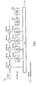
- Fig. 4 gives a more detailed view of a possible implementation of the RLC layer 5a of a GPRS protocol stack according to the present invention.
- RLC buffers 51-2a .. 51-5a are provided for buffering the RLC frames (containing the LLC frames) that are to be handed to the MAC layer 8.
- RLC buffers 51-2a .. 51-5a are provided for the respective RLC-SAPs 50-2a .. 50-5a that offer services to the respective modified LLEs 40-2a .. 40-5a, which in turn offer services to the SNDCP 7-3 via respective LLC-SAPs 43-2 .. 43-5.
- the flow control instance 52a operates an XOn/XOff protocol between the RLC buffers 51-2a .. 51-5a and the respective modified LLEs 40-2a .. 40-5a, so that the modified RLC layer 5a can select from which modified LLE to receive further LLC frames from, depending on knowledge on the state of the physical transmission channel 9, which is provided to the flow control instance by a channel state instance 53a.
- the channel state instance 53a may either determine the state of the physical transmission by its own or may receive information on the state of the physical transmission channel from higher or lower protocol layers.
- the invention has been described above by means of only one out of a multiplicity of possible embodiment. It should be noted that there are alternative ways and variations which are obvious to a skilled person in the art and can be implemented without deviating from the scope of the appended claims, e.g. the invention can be used to improve the flow control in other, not necessarily wireless communication systems to overcome the bottleneck of a multiplexer in a multi-layered protocol stack. Various kinds of flow control mechanisms between the protocol layers of interest are possible. In particular, it is also possible to have hybrid systems, where the separate flow control of both a multiplexed bundle of LLC frames and of non-multiplexed LLC frames is performed.
Landscapes
- Engineering & Computer Science (AREA)
- Computer Networks & Wireless Communication (AREA)
- Signal Processing (AREA)
- Databases & Information Systems (AREA)
- Communication Control (AREA)
- Computer And Data Communications (AREA)
- Mobile Radio Communication Systems (AREA)
Abstract
Description
- The invention relates to a system and a device for controlling the flows of a plurality of Data Units (DUs) over logical links. The invention further relates to a method and a computer program product for controlling the flows of a plurality of DUs over a logical link.
- Data transfer in cellular radio systems such as the Global System for Mobile Communications (GSM) or the Universal Mobile Telecommunications System (UMTS) is growing more and more complex with the advent of a mix of advanced multi-media applications and services. For optimum use and fair distribution of the scarce radio resource, more sophisticated data flow control techniques are required, where "flow control" is understood as the management of data flow between nodes of the cellular radio system, e.g. the mobile and base stations, so that the data can be handled at an efficient pace. Too much data arriving before a device at one of said nodes can handle it causes data overflow, meaning the data is either lost or must be retransmitted. An example for sophisticated data flow control techniques is the introduction of priority-based data flow control, where data is assigned a Quality of Service (QoS) parameter and/or a pre-defined service class and where data flow then is handled under consideration of the QoS parameter and/or service class, e.g. in order to optimise transfer of the data with the highest QoS requirements. Lack of proper priority-based data flow control can result in resources being wasted for lower priority services, ultimately dissatisfying the mobile subscriber.
-
Fig. 1 depicts a part of the protocol stack of the General Packet Radio Service (GPRS) that has been integrated into the GSM protocol stack in the scope of theGSM phase 2+ development in order to use the GSM radio resources more efficiently. The GPRS protocol stack controls the communication of a Mobile Station (MS) 1 and a Serving GPRS Support Node (SGSN) 2 via a Base Station Subsystem (BSS) 3. - In the sequel, the Logical Link Control (LLC)
layer 4 of the GPRS protocol stack as depicted inFig. 1 will be of primary interest. This layer and its functionality is standardised by the European Telecommunications Standardisation Institute (ETSI) and described in technical document 3GPP TS 04.64 (version 8.7.0, December 2001). - The
LLC layer 4 is considered as sub-layer of layer-2 in the ISO/OSI 7-layer reference model and operates above the Radio Link Control (RLC)layer 5 and Base Station Subsystem GPRS Protocol (BSSGP)layer 6 to provide logical links between layer-3 entities in a MS 1 and layer-3 peer entities in its associated SGSN 2. Above theLLC layer 4, i.e. in the network layer (layer-3 of the ISO/OSI model) 7, are located the Tunnelling of Messages (TOM) protocol 7-1, the GPRS Mobility Management (GMM) protocol 7-2, the Sub-Network Dependent Convergence (SNDC) layer 7-3, and the SMS protocol 7-4. - The RLC
protocol 5 in combination with the Medium Access Control (MAC)protocol 8 operates on top of the GSM Radio Frequency (RF) channel (physical layer) 9 and realises the reliable packet-oriented transmission betweenMS 1 andBSS 3 by statistical multiplexing of several logical connections on the Packet Data Channels (PDCHs) available for GPRS in a radio cell. While RLC/MAC contains already an Automatic Repeat Request (ARQ) scheme to handle transmission errors on the air interface, theLLC protocol 4 provides a reliable ciphered logical link betweenMS 1 and SGSN 2 by applying flow control and error handling mechanisms known from link layer protocols like the Integrated Services Digital Network (ISDN). The ARQ scheme in LLC is not designed to handle transmission errors on the air interface, but for handling frame losses and errors in the fixed network or for link recovery after a cell change. The BSSGP 6, which is operating on top of anetwork service 10 such as Frame Relay (FR) and an underlying layer-1 (L1)protocol 11, is responsible for flow control betweenBSS 3 and SGSN 2. The conversion between theRLC protocol 5 and the BSSGPprotocol 6 is performed by means of arelay 12 in theBSS 3. - The TOM protocol 7-1 is a generic protocol layer used for the exchange of TOM protocol envelopes between the MS 1 and the SGSN 2. The GMM protocol 7-2 uses the services of the
LLC layer 4 to transfer messages between theMS 1 and the SGSN 2. It includes functions such as attachment and authentication, and transport of session management messages for functions such as PDP context activation and deactivation. Network layer protocols are intended to be capable of operating services derived from a wide variety of sub-networks and data links. GPRS supports several network layer protocols providing protocol transparency for the users of the service. Therefore, all functions related to transfer of network layer PDUs are carried out in a transparent way by the GPRS network entities. SNDCP 7-3 provides this adaptation of different network layers to the logical link by mapping different packet data protocols (e.g., Internet Protocol (IP) data packets) onto the services provided by the LLC layer.
The SMS protocol 7-4 uses the services of theLLC layer 4 to transfer short messages between theMS 1 and SGSN 2. -
Fig. 2 gives a more detailed view of the structure of theLLC layer 4 as seen from theMS 1 side, wherein the signalling transfer between the components ofFig. 2 is given in dashed lines and the joint signalling and data transfer is given in solid lines. TheLLC layer 4 comprises a plurality of LLC Entities (LLEs) 40-1 .. 40-8, anLLC management entity 41, amultiplexer 42, and a plurality of LLC-SAPs 43-1 .. 43-9. Via the SAPs 43-1 43-8, the services of the LLEs 40-1 40-8 are provided for the protocols of thenetwork layer 7, i.e. the SMS protocol 7-1, the GMM protocol 7-2, the SNDCP 7-3 and the TOM protocol 7-4. There exists also a pure signalling link between the GMM protocol 7-2 and theLLC management entity 41 via the SAP 43-9. Below theLLC layer 4, theRLC layer 5 and theMAC layer 8 are situated. The LLC frames from themultiplexer 42 are passed to theRLC layer 5 via one single RLC-SAP 50-1. - The
LLC layer 4 provides four LLC-SAPs 43-2 .. 43-5 to the SNDCP 7-3, where the SNDCP 7-3 manages the actual data packet transmission. In GPRS, four radio priority levels are defined. Correspondingly, four LLC-SAPs are required for packet data transmission, wherein the SAP Identifier (SAPI) identifies the point at which LLC services are provided by an LLC entity to a network layer entity. The SAPIs for said four radio priority levels are SAPI=3, 5, 9 and 11, respectively. The services that are made available via the LLC-SAPs 43-2 .. 43-5 are provided by the LLEs 40-2 .. 40-5. Each LLE controls the information flow of N-PDUs that are transferred as LLC Service Data Units (LLC-SDUs) within LLC-PDUs on the LLC link/connection between peer LLEs in theMS 1 andSGSN 2, respectively. These N-PDUs are transferred between the LLE and the above SNDCP 7-3 via a corresponding LLC-SAP. LLEs provide the SNDCP 7-3 unacknowledged/acknowledged information transfer, flow control (in Asynchronous Balanced Mode) and frame error detection. Each LLC connection is identified by a Data Link Connection Identifier (DLCI) that consists of a SAPI and a Temporary Logical Link Identifier (TLLI). As already stated. The SAPI is used to identify the SAP on theSGSN 2 side and theMS 1 side of the LLC interface, SAPI is carried in the address field of each LLC frame. The TLLI is used to identify aspecific MS 1. TLLI assignments is controlled by GMM. TLLI is not carried in LLC frames. - The
multiplexer 42 represents an entity that multiplexes the LLC connections of the respective LLEs 40-1 .. 40-8 and outputs LLC frames (LLC-PDUs) that are transferred to the peer multiplexer entity in the remote SGSN 2LLC layer 4. On LLC frame transmission, themultiplexer 42 generates and inserts the Frame Check Sequence (FCS), performs the frame ciphering function, and provides SAPI-based LLC layer contention resolution between the various LLEs 40-1 .. 40-8 whose connections are multiplexed. On LLC frame reception, themultiplexer 42 performs the frame decipher function and checks the FCS. If the frame passes the FCS check, the multiplex procedure distributes the LLC frame to the appropriate LLE. For the ciphering function, a ciphering key is produced with the ciphering algorithm, for instance starting from an identification key and a non-predictable random number generated by an authentication centre. The FCS typically consists of a 24 bit cyclic redundancy check (CRC) code. The CRC-24 is used to detect bit errors in the frame header and information fields. - When being passed to the
RLC layer 5 via the RLC-SAP 50-1, the LLC frames from themultiplexer 42 are segmented into RLC data blocks. At theRLC layer 5 andMAC layer 8, a selective ARQ between theMS 1 and the network provides retransmission of erroneous RLC data blocks. When a complete LLC frame is successfully transferred across the RLC layer, it is forwarded to the peer LLC entity in theSGSN 2. - By multiplexing the connections of the different LLEs 40-1 .. 40-8 into LLC frames, the
multiplexer 42 provides a common interface between theLLC layer 4 and the RLC layer 5 (via the single RLC-SAP 50-1) for all signalling and data transfers. However, the multiplexer also represents a bottleneck for smooth data flow of the different LLC connections that are controlled by the respective LLEs 40-1 .. 40-8. This is due to the fact that the RLC layer, which has a good view of the radio resources that are available for the transmission of its RLC data blocks, has no possibility to separately control the data flows of the different LLC connections over the single RLC-SAP 50-1 due to the multiplexing procedure. It is thus not possible for theRLC layer 5 to adapt the flows of the different LLC connections with their different QoS requirements to the transmission state of the underlying radio resource, a fact that deteriorates the overall data flow of the LLC-PDUs over the LLC links and thus also the flow of the N-PDUs that are contained as LLC-SDUs in the LLC-PDUs. - Prior art document
WO 00/10334 A2 - It is thus an object of the present invention to provide an improved control of the flow of data units over logical links in a communication system that operates a multi-layered protocol stack.
- It is proposed that a device for controlling the flows of a plurality of Data Units (DUs) over logical links comprises at least two first-type Link Control (LC) means, wherein each first-type LC means transforms a first-type DU into a second-type DU and vice versa, and provides a first interface for said first-type DUs and a second interface for said second type DUs, and a second-type LC means with interfaces for said second-type DUs, wherein the second interface of each of said first-type LC means is directly connected to one respective interface of said second-type LC means, and wherein said second-type LC means comprises means for separately controlling the respective flows of the second-type DUs, which are transferred over its respective interfaces.
- Said device may for instance represent a mobile terminal, in particular a mobile phone, a Personal Digital Assistant (PDA), or a computer equipped with a network card, in a communication system operated according to the GPRS standard or derivatives thereof, or may constitute a part of such a terminal.
- As compared to the prior art, the present invention omits the use of a multiplexer that multiplexes the respective second-type DUs, which are transferred via the second interfaces of the respective first-type LC means, and that transfers the multiplexed second-type DUs via a single interface of a second LC means. Instead, the present invention proposes a second-type LC means with several interfaces, wherein each of said interfaces is directly connected to one respective second interface of each of said at least two first-type LC means. The second-type LC means is equipped with means to control the flows of the second-type DUs over its respective interfaces. As a result, the present invention allows to separately control the flows of respective second-type DUs that have been transformed from respective first-type DUs in respective first-type LC means. Due to the one-to-one relationship of the first-type DUs and the second-type DUs that have been transformed by the same first-type LC means, the second-type LC means is thus able to control the flows of the respective first-type DUs that are transferred via respective first interfaces of said respective first-type LC means, as well. In other words, according to the present invention, the flows of the respective first-type DUs that are passed to respective first interfaces of the respective first-type LC means can be controlled by said second-type LC means.
- According to the device of the present invention, it is preferred that said first-type LC means transforms said first-type DU into a second-type DU and vice versa by performing at least a frame check function and a ciphering function. The omission of the prior-art multiplexer requires partial functionality of the multiplexer, at least the insertion and the check of a frame check sequence and the ciphering and de-ciphering of frames, to be integrated into each of said first-type LC means. The transformation of first-type DUs into second-type DUs then comprises insertion of a frame check sequence and ciphering, whereas the transformation of second-type DUs into first-type DUs comprises at least deciphering and checking of the frame check sequence. Note that, according to the device of the present invention, it is still possible to have the prior art set-up with first-type DUs that do not perform a frame check function and ciphering function, and whose DUs, that are transferred via their respective second interfaces, are multiplexed by a multiplexer, that performs the frame check function and ciphering function, and transferred via a separate interface of said second-type LC means. The present invention only demands that there exist at least two first-type LC means with frame checking and ciphering functionality and that said second-type LC means has interfaces to be connected exclusively to the second interfaces of said at least two first-type LC means. An interface of the multiplexer thus can be connected to a further interface of said second-type LC means, but separate flow control then is only possible for the DUs that have been transformed by the first-type LC means without being multiplexed afterwards, whereas the flow of the multiplexed DUs can only be jointly controlled.
- According to the device of the present invention, it is further preferred that at least two first-type LC means can be differentiated by characteristics of the first-type DUs that are transferred via their respective first interfaces, and that said means for separately controlling the respective flows of the second-type DUs, which are transferred over said respective interfaces of said second-type LC means, controls said respective flows of said second-type DUs under consideration of said characteristics of the first-type DUs to which or from which said second-type DUs are transformed. The at least two distinguishable first-type LC means are thus suited for the transfer and transformation of at least two different types of first-type DUs, and due to the direct connection between the second interfaces of each first-type LC means with a respective interface of said second-type LC means and the ability of the second-type LC means to separately control the flows of the second-type DUs that are transferred via its respective interfaces, the flow of the first-type DUs that are transferred via the first interfaces of said at least two distinguishable first-type LC means can be controlled by said second LC means. Equally well, it is possible to have as many distinguishable first-type LC means (and corresponding first-type DUs) as there are interfaces of the second-type LC means.
- According to the device of the present invention, it is preferred that said second-type LC means comprises at least one DU buffer for buffering second-type DUs that are transferred over its respective interfaces. The DU buffer stores the second-type DUs that are to be transferred over a joint transmission link that may at least be partially controlled by the second-type LC means.
- According to the device of the present invention, it is further preferred that said means for separately controlling the respective flows of the second-type DUs, which are transferred over said respective interfaces of said second-type LC means, controls said respective flows of said second-type DUs under consideration of said characteristics of the first-type DUs to which or from which said second-type DUs are transformed, and under consideration of the state of said at least one DU buffer. Then the respective flows of said second-type DUs over the respective interfaces of said second-type DU can be adapted to the state of the buffer. The state of the buffer may describe the number of stored DUs, the number of free storage units, information on the velocity or storage and clearance of the buffer, etc.. For instance, if the buffer is only cleared slowly, the second-type LC means may decrease the flow of all second-type DUs, or may only decrease the flow of second-type DUs over one of its respective interfaces.
- According to the device of the present invention, it is further preferred that said second-type LC means comprises means for evaluating the state of a physical transmission link over which said second-type DUs are transferred. Said second-type DUs can either be directly or indirectly transferred over said physical transmission link, i.e. it is well possible that there are further LC means located between said second-type LC means and said physical transmission link. Correspondingly, said second-type DUs may be further transformed before being transferred over said physical transmission channel or not. The state of the physical transmission link may be characterised by any parameter or combination of parameters that is relevant for data transmission, for instance the available transmission bandwidth, error characteristics, delay characteristics, signal-to-noise or carrier-to-interference ratios, etc..
- According to the device of the present invention, it is further preferred that said means for separately controlling the respective flows of the second-type DUs, which are transferred over said respective interfaces of said second-type LC means, controls said respective flows of said second-type DUs under consideration of said characteristics of the first-type DUs to which or from which said second-type DUs are transformed, and under consideration of the state of said physical transmission link over which said second-type DUs are transferred. Both the characteristics of the distinguishable first-type DUs and the state of the physical transmission link thus determine the flow control.
- According to the device of the present invention, it is further preferred that said means for separately controlling the respective flows of the second-type DUs, which are transferred via said respective interfaces of said second-type LC means, comprises means for operating a flow control protocol. The flow control protocol controls the respective flows of the second-type DUs over said respective interfaces of said second-type LC means and may communicate with the respective first-type LC means by control commands in order to request further second-type DUs that may be stored in buffers of said first-type LC means or to block further sending of second-type DUs from the buffers of the first-type LC means.
- According to the device of the present invention, it is further preferred that said flow control protocol is the XOn/XOff flow control protocol. Therein, the receiving data buffer sends an XOff command to the sending data buffer when the receiving buffer is full, and sends an XOn command to the sending data buffer when it is ready for further data buffering. Also other flow control protocols are possible.
- According to the device of the present invention, it is further preferred that said characteristics are the Quality of Service (QoS) requirements of said first-type DUs. The first-type DUs that are transformed by said first-type LC means into second-type LC means then can be differentially prioritised by said second-type LC means. For instance, when said buffer of said second-type LC means is filling more and more, said second-type LC means may reduce the flow of the second-type DUs that correspond to said first-type DUs with the lowest QoS requirements, so that at least the second-type DUs with the higher QoS requirements can be further processed by means that follow said buffer in said second-type LC means, wherein said means that follow said buffer may for instance be the sender/receiver of said physical transmission link or a further LC means that controls said physical transmission link. QoS requirements may comprise information on the availability of the network, the throughput (effective data rate), the packet loss, the latency (delay) and jitter (latency variation).
- According to the device of the present invention, it is preferred that the device further comprises a link management means that controls said first-type LC means. Said control may for instance comprise parameter initialisation, error processing and connection flow control invocation.
- According to the device of the present invention, it is preferred that said logical links are the logical links between Mobile Station (MS) and the Serving GPRS Support Node (SGSN) of a mobile radio device operated according to the General Packet Radio Service (GPRS) standard or a derivative thereof, that said first-type LC means are the Logical Link Control (LLC) entities of the GPRS LLC protocol with additional sequence-based frame checking and ciphering functionality, that said first interfaces are the Service Access Points of the LLC entities (LLC-SAPs), that said second-type DUs are LLC frames, that said interfaces of said second-type LC means are Radio Link Control (RLC)-SAPs, that said first-type DUs are N-PDUs of the GPRS Network layer protocol, and that said second-type LC means implements the functionality of the GPRS RLC protocol and further comprises said means for separately controlling the respective flows of the LLC frames, which are transferred via said respective RLC-SAPs.
- The N-PDUs with different QoS requirements, e.g. representing N-PDUs of the SNDCP, have to be transferred between peer entities in the MS network layer and the SGSN network layer, respectively, by encapsulating them as LLC-SDUs in LLC-PDUs that are transferred over logical links between peer LLEs. According to the invention, the connections between the LLEs that are made available to the network layer at the LLC-SAPIs can now be controlled separately for each LLC-SAPI, because, according to the device of the present invention, the LLC connections are no longer multiplexed before using the RLC connection service at a single RLC-SAP, but separately use respective RLC connections that are made available at several respective RLC-SAPs. With the omission of the prior-art LLC multiplexer, there exists virtually no flow obstruction between the RLC entities and the network layer entities, e.g. the SNDCP entities. The RLC layer thus can have full data flow control of the data that is to be transferred over each LLC-SAP. The RLC layer communicates directly with the LLEs for both the up- and downlink data flow, for instance by an XOn/XOff flow control protocol, wherein the LLEs have their own small buffers. If there arise problems in the RLC buffers or on the radio link, flow control can suspend the transmission of low priority SNDCP PDUs and maintain the transmission of high priority SNDCP PDUs instead. Apart from the fact that the number of primitives between the entities is significantly reduced, which results in reduced MCU load and buffer usage, the multiplexer itself and its expensive buffers can be omitted.
- It is further proposed a communication system for controlling the flows of a plurality of Data Units, DUs, over logical links comprising a device according to the present invention.
- It is further proposed that a method for controlling the flows of a plurality of Data Units (DUs) over logical links comprises the steps of transferring first type Data Units (DUs) via respective first interfaces of at least two first-type Link Control (LC) means; transforming said first-type DUs into second-type DUs and vice versa in said respective first-type LC means; transferring said second-type DUs via respective second interfaces of said first-type LC means; transferring said second-type DUs via respective interfaces of a second-type LC means, wherein said second interface of each of said first-type LC means is directly connected to one respective interface of said second-type LC means; and separately controlling the respective flows of the second-type DUs, which are transferred over the respective interfaces of said second-type LC means.
- According to the method of the present invention, it is preferred that said step of transforming said first-type DUs into second-type DUs and vice versa comprises at least a frame check function and a ciphering function.
- According to the method of the present invention, it is preferred that at least two first-type LC means can be differentiated by characteristics of the first-type DUs that are transferred via their respective first interfaces, and that in said step of separately controlling said respective flows of the second-type DUs over said respective interfaces, said characteristics of the first-type DUs to which or from which said second-type DUs are transformed are considered.
- According to the method of the present invention, it is preferred that said method further comprises the step of buffering second-type DUs that are transferred over said respective interfaces of said second-type LC means in at least one DU buffer.
- According to the method of the present invention, it is preferred that in said step of separately controlling said respective flows of the second-type DUs over said respective interfaces, said characteristics of the first-type DUs to which or from which said second-type DUs are transformed, and the state of said at least one DU buffer are considered.
- According to the method of the present invention, it is preferred that said method further comprises the step of evaluating the state of a physical transmission link over which said second-type DUs are transferred.
- According to the method of the present invention, it is preferred that in said step of separately controlling said respective flows of the second-type DUs over said respective interfaces, said characteristics of the first-type DUs to which or from which said second-type DUs are transformed, and said evaluated state of said transmission link are considered.
- According to the method of the present invention, it is preferred that said step of separately controlling said respective flows of the second-type DUs over said respective interfaces comprises the steps required for operating a flow control protocol.
- According to the method of the present invention, it is preferred that said flow control protocol is the XOn/XOff flow control protocol.
- According to the method of the present invention, it is preferred that said characteristics are the Quality of Service (QoS) requirements of said first-type DUs.
- According to the method of the present invention, it is preferred that the method further comprises the step of controlling said first-type LC means by a link management means.
- According to the method of the present invention, it is preferred that said logical links are the logical links between a Mobile Station (MS) and a Serving GPRS Support Node (SGSN) of a mobile radio system operated according to the General Packet Radio Service (GPRS) standard or a derivative thereof, that said first-type LC means are the Logical Link Control (LLC) entities of the GPRS LLC protocol with additional sequence-based frame checking and ciphering functionality, that said first interfaces are the Service Access Points of the LLC entities (LLC-SAPs), that said second-type DUs are LLC frames, that said interfaces of said second-type LC means are Radio Link Control (RLC)-SAPs, that said first-type DUs are N-PDUs of the GPRS Network layer protocol, and that said second-type LC means implements the functionality of the GPRS RLC protocol and further performs the step of separately controlling the respective flows of the LLC frames, which are transferred via at least two of the RLC-SAPs, under consideration of the characteristics of the N-PDUs to which or from which said LLC frames are transformed.
- Furthermore, a computer program product is proposed, wherein said computer program product is directly loadable into the internal memory of a digital computer, and comprises software code portions for performing the method steps of the above mentioned method claims when said product is run on a computer.
- These and other aspects of the invention will be apparent from and elucidated with reference to the embodiments described hereinafter. In the figures show:
- Fig. 1:
- an overview of the lower three protocol layers of the prior art protocol stack of the General Packet Radio Service (GPRS) system,
- Fig. 2:
- a detailed view of the structure of the prior art LLC and RLC layers of a GPRS protocol stack as seen from the Mobile Station (MS) side,
- Fig. 3:
- a detailed view of the structure of the LLC and RLC layers of a GPRS protocol stack as seen from the MS side according to the present invention, and
- Fig. 4:
- a detailed view of the structure of the RLC layer as seen from the MS side according to the present invention.
-
Fig. 3 depicts the structure of the Logical Link Control (LLC) 4a and Radio Link Control (RLC) 5a layers of a GPRS protocol stack as seen from theMS 1 side, containing the modifications according to the present invention. The modifications of the prior art protocol stack as depicted inFig. 1 and2 only affect theLLC layer 4a and theRLC layer 5a. For the description of thenetwork layer 7 above theLLC layer 4a and of the Medium Access Control (MAC)layer 8 below theRLC layer 5a, it is referred to the corresponding description of the prior art inFigs. 1 and2 . - In contrast to the prior art protocol stack of
Fig. 2 , the protocol stack according to the present invention comprises a modifiedLLC layer 4a, which is deprived of itsmultiplexer 42. The multiplexer functionality has been moved to the modified LLC entities (LLEs) 40-1a 40-8a, which are each connected to one LLC Service Access Point (LLC-SAPs) 43-1 .. 43-8, respectively. The modified LLEs 40-1a .. 40-8a are no longer connected to theprior art multiplexer 42, but are connected with MAC-SAPs 50-1a .. 50-8a, respectively. The modified LLEs 40-1a .. 40-8a are still controlled by anLLC management entity 41. - User data packets, for instance Internet Protocol (IP) data packets, are adapted to the services provided by the
LLC layer 4a by means of the Sub-Network Dependent Convergence Protocol (SNDCP). The SNDCP uses Network Protocol Data Units (N-PDUs) to transfer the information of user data packets between network layer peer entities. The transfer of N-PDUs between network entities uses QoS-dependent LLC connections that are provided by the modified LLEs 40-2a .. 40-5a and made available to the network layer via the LLC-SAPs 43-2 .. 43-5. In theLLC layer 4a, N-PDUs are transmitted as LLC Service Data Units (LLC-SDU) that are part of LLC-PDUs (LLC frames). The LLC PDUs are transferred between peer LLC entities in theMS 1 andSGSN 2, respectively, by using the connections offered by the underlying RLC layer. Once again, the LLC-PDUs are then transmitted as LLC-SDUs as part of RLC-PDUs. - Due to the omission of the
prior art multiplexer 42, LLC frames are no longer multiplexed, so that there exists one RLC-SAP 50-1a .. 50-8a for each modified LLE 40-1a .. 40-8a. The frame checking and ciphering, which was the task of theprior art multiplexer 42, is now performed by the modified LLEs 40-1a .. 40-8a, i.e. insertion of a frame check sequence and ciphering of the frame upon frame transmission and deciphering and check of the frame check sequence upon frame reception. - The modified
RLC layer 5a now advantageously controls the flow of LLC frames that correspond to different QoS requirements of the N-PDUs they are related to, respectively. This is achieved by operating an XOn/XOff protocol between the modifiedRLC layer 5a and the modified LLEs 40-1a .. 40-8a. The modifiedRLC layer 5a thus can choose from which modified LLE buffer to receive further LLC frames from by sending XOn ("send more LLC frames") or XOff ("do not send more LLC frames") messages to the modified LLEs 40-1a .. 40-8a, accordingly. The modifiedRLC layer 5a comprises at least one buffer for buffering the RLC frames that are to be handed to theMAC layer 8 for transmission over aphysical propagation channel 9, and possesses means to evaluate the current state of saidphysical transmission channel 9. Being aware of the state of thephysical transmission channel 9, the state of its buffer and the QoS requirements of the respective LLC frames that can be separately polled from the respective buffers in the respective modified LLEs 40-1a .. 40-8a, the modifiedRLC layer 5a now can adapt the transmission of LLC frames over saidphysical transmission channel 9 to the QoS requirements of the LLC frames. When the channel is bad and the buffer starts to fill more and more, it is advisable to suspend the transmission of LLC frames with low QoS requirements and to concentrate on the transmission of LLC frames with higher QoS requirements. This kind of flow control of the respective LLC frames is performed on both the up- and downlink. It reduces the number of service primitives that is required for communication between the protocol entities and thus helps to reduce MCU load. Furthermore, buffer usage is reduced. The flow control of the N-PDUs that are transmitted between network entities inMS 1 andSGSN 2 under usage of the QoS-specific LLC connections is, due to the improved flow control betweenLLC 4a andRLC layer 5a, more granular and more adaptive to the state of thephysical transmission link 9. -
Fig. 4 gives a more detailed view of a possible implementation of theRLC layer 5a of a GPRS protocol stack according to the present invention. Within the modifiedRLC layer 5a, RLC buffers 51-2a .. 51-5a are provided for buffering the RLC frames (containing the LLC frames) that are to be handed to theMAC layer 8. In this exemplary implementation, RLC buffers 51-2a .. 51-5a are provided for the respective RLC-SAPs 50-2a .. 50-5a that offer services to the respective modified LLEs 40-2a .. 40-5a, which in turn offer services to the SNDCP 7-3 via respective LLC-SAPs 43-2 .. 43-5. The RLC buffers 51-2a .. 51-5a are controlled by aflow control instance 52a. Theflow control instance 52a operates an XOn/XOff protocol between the RLC buffers 51-2a .. 51-5a and the respective modified LLEs 40-2a .. 40-5a, so that the modifiedRLC layer 5a can select from which modified LLE to receive further LLC frames from, depending on knowledge on the state of thephysical transmission channel 9, which is provided to the flow control instance by achannel state instance 53a. Thechannel state instance 53a may either determine the state of the physical transmission by its own or may receive information on the state of the physical transmission channel from higher or lower protocol layers. - The invention has been described above by means of only one out of a multiplicity of possible embodiment. It should be noted that there are alternative ways and variations which are obvious to a skilled person in the art and can be implemented without deviating from the scope of the appended claims, e.g. the invention can be used to improve the flow control in other, not necessarily wireless communication systems to overcome the bottleneck of a multiplexer in a multi-layered protocol stack. Various kinds of flow control mechanisms between the protocol layers of interest are possible. In particular, it is also possible to have hybrid systems, where the separate flow control of both a multiplexed bundle of LLC frames and of non-multiplexed LLC frames is performed.
Claims (26)
- A device for controlling the flows of a plurality of Data Units, DUs, over logical links, comprising:- at least two first-type Link Control, LC, means (40-1a .. 40-8a), wherein each first-type LC means (40-1a .. 40-8a) is adapted to transform a first-type DU into a second-type DU and vice versa, and provides a first interface (43-1 .. 43-8) for said first-type DUs and a second interface for said second type DUs, and- a second-type LC means (5a) with interfaces (50-1a .. 50-8a) for said second-type DUs, wherein the second interface of each of said first-type LC means (40-1a .. 40-8a) is directly connected to one respective interface (50-1a .. 50-8a) of said second-type LC means (5a),characterised in
that said second-type LC means (5a) comprises means (52a) for separately controlling the respective flows of the second-type DUs, which are transferred over its respective interfaces (50-1a .. 50-8a). - The device according to claim 1, wherein said first-type LC means (40-1a .. 40-8a) is adapted to transform said first-type DU into a second-type DU and vice versa by performing at least a frame check function and a ciphering function.
- The device according to any of the claims 1-2,- wherein at least two first-type LC means (40-1a .. 40-8a) can be differentiated by characteristics of the first-type DUs that are transferred via their respective first interfaces (43-1 .. 43-8), and- wherein said means (52a) for separately controlling the respective flows of the second-type DUs, which are transferred over said respective interfaces (50-1a .. 50-8a) of said second-type LC means (5a), is adapted to control said respective flows of said second-type DUs under consideration of said characteristics of said first-type DUs to which or from which said second-type DUs are transformed.
- The device according to claim 3, wherein said second-type LC means (5a) comprises at least one DU buffer (51-2a .. 51-5a) for buffering second-type DUs that are transferred over its respective interfaces (50-1a .. 50-8a).
- The device according to claim 4, wherein said means (52a) for separately controlling the respective flows of the second-type DUs, which are transferred over said respective interfaces (50-1a .. 50-8a) of said second-type LC means (5a), is adapted to control said respective flows of said second-type DUs under consideration of said characteristics of the first-type DUs to which or from which said second-type DUs are transformed, and under consideration of the state of said at least one DU buffer (51-2a ... 51-5a).
- The device according to claim 3, wherein said second-type LC means (5a) comprises means (53a) for evaluating the state of a physical transmission link (9) over which said second-type DUs are transferred.
- The device according to claim 6, wherein said means (52a) for separately controlling the respective flows of the second-type DUs, which are transferred over said respective interfaces (50-1a .. 50-8a) of said second-type LC means (5a), is adapted to control said respective flows of said second-type DUs under consideration of said characteristics of the first-type DUs to which or from which said second-type DUs are transformed, and under consideration of the state of said physical transmission link (9) over which said second-type DUs are transferred.
- The device according to any of the claims 1-7, wherein said means (52a) for separately controlling the respective flows of the second-type DUs, which are transferred via said respective interfaces (50-1a .. 50-8a) of said second-type LC means (5a), comprises means for operating a flow control protocol.
- The device according to claim 8, wherein said flow control protocol is the XOn/XOff flow control protocol.
- The device according to any of the claims 3-9, wherein said characteristics are the Quality of Service, QoS, requirements of said first-type DUs.
- The device according to any of the claims 1-10, further comprising a link management means (41) adapted to control said first-type LC means (40-1a .. 40-8a).
- The device according to any of the claims 3-11, wherein said logical links are the logical links between Mobile Station, MS, (1) and the Serving GPRS Support Node, SGSN, (2) of a mobile radio system operated according to the General Packet Radio Service, GPRS, standard or a derivative thereof, wherein said first-type LC means (40-1a .. 40-8a) are the Logical Link Control, LLC, entities of the GPRS LLC protocol with additional sequence-based frame checking and ciphering functionality, wherein said first interfaces (43-1 .. 43-8) are the Service Access Points, LLC-SAPs, of the LLC entities (40-1a .. 40-8a), wherein said second-type DUs are LLC frames, wherein said interfaces (50-1a .. 50-8a) of said second-type LC means are Radio Link Control, RLC-SAPs, wherein said first-type DUs are N-PDUs of the GPRS Network layer protocol (7), and wherein said second-type LC means (5a) implements the functionality of the GPRS RLC protocol and further comprises said means (52a) for separately controlling the respective flows of the LLC frames, which are transferred via said respective RLC-SAPs (50-1a .. 50-8a).
- A communication system for controlling the flows of a plurality of Data Units, DUs, over logical links, comprising a device according to any of the claims 1-7.
- A method for controlling the flows of a plurality of Data Units, DUs, over logical links, comprising the steps of:- transferring first type Data Units, DUs, via respective first interfaces (43-1 .. 43-8) of at least two first-type Link Control, LC, means (40-1a .. 40-8a);- transforming said first-type DUs into second-type DUs and vice versa in said respective first-type LC means (40-1a .. 40-8a) ;- transferring said second-type DUs via respective second interfaces of said first-type LC means (40-1a .. 40-8a); and- transferring said second-type DUs via respective interfaces (50-1a .. 50-8a) of a second-type LC means (5a), wherein said second interface of each of said first-type LC means (40-1a .. 40-8a) is directly connected to one respective interface (50-1a .. 50-8a) of said second-type LC means (5a) ;characterised in
that the method further comprises separately controlling the respective flows of the second-type DUs, which are transferred over the respective interfaces (50-1a .. 50-8a) of said second-type LC means (5a). - The method according to claim 14, wherein said step of transforming said first-type DUs into second-type DUs and vice versa comprises at least a frame check function and a ciphering function.
- The method according to any of the claims 14-15,- wherein at least two first-type LC means (40-1a .. 40-8a) can be differentiated by characteristics of the first-type DUs that are transferred via their respective first interfaces, and- wherein in said step of separately controlling said respective flows of the second-type DUs over said respective interfaces (50-1a .. 50-8a), said characteristics of the first-type DUs to which or from which said second-type DUs are transformed are considered.
- The method according to claim 16, wherein said method further comprises the step of buffering second-type DUs that are transferred over said respective interfaces (50-1a .. 50-8a) of said second-type LC means (5a) in at least one DU buffer (51-2a .. 51-5a).
- The method according to claim 17, wherein in said step of separately controlling said respective flows of the second-type DUs over said respective interfaces (50-1a .. 50-8a), said characteristics of the first-type DUs to which or from which said second-type DUs are transformed, and the state of said at least one DU buffer (51-2a .. 51-5a) are considered.
- The method according to claim 16, wherein said method further comprises the step of evaluating the state of a physical transmission link (9) over which said second-type DUs are transferred.
- The method according to claim 19, wherein in said step of separately controlling said respective flows of the second-type DUs over said respective interfaces (50-1a .. 50-8a), said characteristics of the first-type DUs to which or from which said second-type DUs are transformed, and said evaluated state of said transmission link (9) are considered.
- The method according to any of the claims 14-20, wherein said step of separately controlling said respective flows of the second-type DUs over said respective interfaces (50-1a .. 50-8a) comprises the steps required for operating a flow control protocol.
- The method according to claim 21, wherein said flow control protocol is the XOn/XOff flow control protocol.
- The method according to any of the claims 16-22, wherein said characteristics are the Quality of Service, QoS, requirements of said first-type DUs.
- The method according to any of the claims 14-23, further comprising the step of controlling said first-type LC means (40-1a .. 40-8a) by a link management means (41).
- The method according to any of the claims 16-24, wherein said logical links are the logical links between a Mobile Station, MS, (1) and a Serving GPRS Support Node, SGSN, 2) of a mobile radio system operated according to the General Packet Radio Service, GPRS, standard or a derivative thereof, wherein said first-type LC means (40-1a .. 40-8a) are the Logical Link Control, LLC, entities of the GPRS LLC protocol with additional sequence-based frame checking and ciphering functionality, wherein said first interfaces (43-1 .. 43-8) are the Service Access Points, LLC-SAPs, of the LLC entities (40-1a .. 40-8a), wherein said second-type DUs are LLC frames, wherein said interfaces (50-1 .. 50-8) of said second-type LC means are Radio Link Control, RLC-SAPs, wherein said first-type DUs are N-PDUs of the GPRS Network layer protocol (7), and wherein said second-type LC means (5a) implements the functionality of the GPRS RLC protocol and further performs the step of separately controlling the respective flows of the LLC frames, which are transferred via at least two of the RLC-SAPs (50-1a .. 50-8a), under consideration of the characteristics of the N-PDUs to which or from which said LLC frames are transformed.
- A computer program product directly loadable into the internal memory of a digital computer, comprising software code portions for performing the method steps of any of the claims 14-25 when said product is run on a computer.
Applications Claiming Priority (1)
| Application Number | Priority Date | Filing Date | Title |
|---|---|---|---|
| PCT/IB2003/003330 WO2005018264A1 (en) | 2003-08-15 | 2003-08-15 | Data flow control for multi-layered protocol stack |
Publications (2)
| Publication Number | Publication Date |
|---|---|
| EP1654899A1 EP1654899A1 (en) | 2006-05-10 |
| EP1654899B1 true EP1654899B1 (en) | 2008-10-22 |
Family
ID=34179246
Family Applications (1)
| Application Number | Title | Priority Date | Filing Date |
|---|---|---|---|
| EP03818091A Expired - Lifetime EP1654899B1 (en) | 2003-08-15 | 2003-08-15 | Data flow control for multi-layered protocol stack |
Country Status (8)
| Country | Link |
|---|---|
| US (1) | US7558204B2 (en) |
| EP (1) | EP1654899B1 (en) |
| CN (1) | CN100542320C (en) |
| AT (1) | ATE412323T1 (en) |
| AU (1) | AU2003251099A1 (en) |
| DE (1) | DE60324337D1 (en) |
| HK (1) | HK1093277A1 (en) |
| WO (1) | WO2005018264A1 (en) |
Families Citing this family (3)
| Publication number | Priority date | Publication date | Assignee | Title |
|---|---|---|---|---|
| KR20070096261A (en) * | 2006-03-23 | 2007-10-02 | 엘지전자 주식회사 | Method of data controling by data link layer in communication system |
| CN101175023B (en) * | 2006-10-30 | 2011-12-28 | 中兴通讯股份有限公司 | Serial connection method for wireless links control layer service data unit |
| US20200145881A1 (en) * | 2018-11-06 | 2020-05-07 | Qualcomm Incorporated | System and method for flow control and buffer status report |
Family Cites Families (7)
| Publication number | Priority date | Publication date | Assignee | Title |
|---|---|---|---|---|
| US6363058B1 (en) * | 1997-09-24 | 2002-03-26 | Telefonaktiebolaget L M Ericsson (Publ) | Multi-service handling by a single mobile station |
| JP3413788B2 (en) * | 1997-09-25 | 2003-06-09 | 日本電信電話株式会社 | Communication method having communication protocol for performing flow control between layers and data communication terminal |
| FI105641B (en) * | 1998-08-10 | 2000-09-15 | Nokia Mobile Phones Ltd | Reservation of resources in packet data transmission |
| FI106762B (en) * | 1999-02-16 | 2001-03-30 | Nokia Mobile Phones Ltd | A method and system for performing some negotiations in a packet data network |
| FI20010998A (en) * | 2001-05-11 | 2002-11-12 | Nokia Corp | High speed data transfer |
| US6920121B2 (en) * | 2003-03-17 | 2005-07-19 | Qprs Limited | Quality packet radio service for a general packet radio system |
| US7266081B2 (en) * | 2003-06-05 | 2007-09-04 | Nokia Corporation | Method and system for arranging data flow control in a data transfer system |
-
2003
- 2003-08-15 EP EP03818091A patent/EP1654899B1/en not_active Expired - Lifetime
- 2003-08-15 AT AT03818091T patent/ATE412323T1/en not_active IP Right Cessation
- 2003-08-15 CN CNB038269155A patent/CN100542320C/en not_active Expired - Fee Related
- 2003-08-15 DE DE60324337T patent/DE60324337D1/en not_active Expired - Lifetime
- 2003-08-15 AU AU2003251099A patent/AU2003251099A1/en not_active Abandoned
- 2003-08-15 WO PCT/IB2003/003330 patent/WO2005018264A1/en active Application Filing
-
2004
- 2004-08-13 US US10/917,840 patent/US7558204B2/en active Active
-
2007
- 2007-01-08 HK HK07100265.1A patent/HK1093277A1/en not_active IP Right Cessation
Also Published As
| Publication number | Publication date |
|---|---|
| AU2003251099A1 (en) | 2005-03-07 |
| WO2005018264A1 (en) | 2005-02-24 |
| DE60324337D1 (en) | 2008-12-04 |
| EP1654899A1 (en) | 2006-05-10 |
| CN100542320C (en) | 2009-09-16 |
| HK1093277A1 (en) | 2007-02-23 |
| ATE412323T1 (en) | 2008-11-15 |
| US7558204B2 (en) | 2009-07-07 |
| US20050058072A1 (en) | 2005-03-17 |
| CN1820532A (en) | 2006-08-16 |
Similar Documents
| Publication | Publication Date | Title |
|---|---|---|
| US7944943B2 (en) | Method and apparatus for MAC layer inverse multiplexing in a third generation radio access network | |
| US6477670B1 (en) | Data link layer quality of service for UMTS | |
| US7616639B2 (en) | Transmitting and receiving control protocol data unit having processing time information | |
| US20060222010A1 (en) | Method of performing a layer operation in a communications network | |
| JP4559766B2 (en) | Flow control method for HSDPA and HSUPA | |
| US9001654B2 (en) | Enhanced multiplexing for single RLC entity | |
| MXPA04009799A (en) | Rlc for realtime multimedia mobile communication system. | |
| JP3739707B2 (en) | Information transport in communication systems | |
| CN101351033B (en) | Data multiplexing method capable of enhancing up access system through multi-carrier | |
| EP1582078A1 (en) | Packet service system and method for controlling packet transmission | |
| EP1654899B1 (en) | Data flow control for multi-layered protocol stack | |
| US7646716B2 (en) | Packet processing in a wireless network | |
| KR100701162B1 (en) | Data flow control for multi-layered protocol stack | |
| US20090257377A1 (en) | Reducing buffer size for repeat transmission protocols | |
| Kalliokulju | User plane architecture of 3/sup rd/generation mobile telecommunication network | |
| Bilgic et al. | Quality of service in general packet radio service | |
| Passas et al. | Supporting UMTS QoS in Wireless LANs |
Legal Events
| Date | Code | Title | Description |
|---|---|---|---|
| PUAI | Public reference made under article 153(3) epc to a published international application that has entered the european phase |
Free format text: ORIGINAL CODE: 0009012 |
|
| 17P | Request for examination filed |
Effective date: 20060111 |
|
| AK | Designated contracting states |
Kind code of ref document: A1 Designated state(s): AT BE BG CH CY CZ DE DK EE ES FI FR GB GR HU IE IT LI LU MC NL PT RO SE SI SK TR |
|
| DAX | Request for extension of the european patent (deleted) | ||
| 17Q | First examination report despatched |
Effective date: 20061026 |
|
| GRAP | Despatch of communication of intention to grant a patent |
Free format text: ORIGINAL CODE: EPIDOSNIGR1 |
|
| GRAS | Grant fee paid |
Free format text: ORIGINAL CODE: EPIDOSNIGR3 |
|
| GRAA | (expected) grant |
Free format text: ORIGINAL CODE: 0009210 |
|
| AK | Designated contracting states |
Kind code of ref document: B1 Designated state(s): AT BE BG CH CY CZ DE DK EE ES FI FR GB GR HU IE IT LI LU MC NL PT RO SE SI SK TR |
|
| REG | Reference to a national code |
Ref country code: GB Ref legal event code: FG4D |
|
| REG | Reference to a national code |
Ref country code: CH Ref legal event code: EP |
|
| REG | Reference to a national code |
Ref country code: IE Ref legal event code: FG4D |
|
| REF | Corresponds to: |
Ref document number: 60324337 Country of ref document: DE Date of ref document: 20081204 Kind code of ref document: P |
|
| NLV1 | Nl: lapsed or annulled due to failure to fulfill the requirements of art. 29p and 29m of the patents act | ||
| PG25 | Lapsed in a contracting state [announced via postgrant information from national office to epo] |
Ref country code: AT Free format text: LAPSE BECAUSE OF FAILURE TO SUBMIT A TRANSLATION OF THE DESCRIPTION OR TO PAY THE FEE WITHIN THE PRESCRIBED TIME-LIMIT Effective date: 20081022 Ref country code: ES Free format text: LAPSE BECAUSE OF FAILURE TO SUBMIT A TRANSLATION OF THE DESCRIPTION OR TO PAY THE FEE WITHIN THE PRESCRIBED TIME-LIMIT Effective date: 20090202 Ref country code: BG Free format text: LAPSE BECAUSE OF FAILURE TO SUBMIT A TRANSLATION OF THE DESCRIPTION OR TO PAY THE FEE WITHIN THE PRESCRIBED TIME-LIMIT Effective date: 20090122 |
|
| PG25 | Lapsed in a contracting state [announced via postgrant information from national office to epo] |
Ref country code: FI Free format text: LAPSE BECAUSE OF FAILURE TO SUBMIT A TRANSLATION OF THE DESCRIPTION OR TO PAY THE FEE WITHIN THE PRESCRIBED TIME-LIMIT Effective date: 20081022 Ref country code: SI Free format text: LAPSE BECAUSE OF FAILURE TO SUBMIT A TRANSLATION OF THE DESCRIPTION OR TO PAY THE FEE WITHIN THE PRESCRIBED TIME-LIMIT Effective date: 20081022 Ref country code: PT Free format text: LAPSE BECAUSE OF FAILURE TO SUBMIT A TRANSLATION OF THE DESCRIPTION OR TO PAY THE FEE WITHIN THE PRESCRIBED TIME-LIMIT Effective date: 20090323 Ref country code: NL Free format text: LAPSE BECAUSE OF FAILURE TO SUBMIT A TRANSLATION OF THE DESCRIPTION OR TO PAY THE FEE WITHIN THE PRESCRIBED TIME-LIMIT Effective date: 20081022 |
|
| PG25 | Lapsed in a contracting state [announced via postgrant information from national office to epo] |
Ref country code: RO Free format text: LAPSE BECAUSE OF FAILURE TO SUBMIT A TRANSLATION OF THE DESCRIPTION OR TO PAY THE FEE WITHIN THE PRESCRIBED TIME-LIMIT Effective date: 20081022 Ref country code: BE Free format text: LAPSE BECAUSE OF FAILURE TO SUBMIT A TRANSLATION OF THE DESCRIPTION OR TO PAY THE FEE WITHIN THE PRESCRIBED TIME-LIMIT Effective date: 20081022 Ref country code: EE Free format text: LAPSE BECAUSE OF FAILURE TO SUBMIT A TRANSLATION OF THE DESCRIPTION OR TO PAY THE FEE WITHIN THE PRESCRIBED TIME-LIMIT Effective date: 20081022 Ref country code: DK Free format text: LAPSE BECAUSE OF FAILURE TO SUBMIT A TRANSLATION OF THE DESCRIPTION OR TO PAY THE FEE WITHIN THE PRESCRIBED TIME-LIMIT Effective date: 20081022 |
|
| PLBE | No opposition filed within time limit |
Free format text: ORIGINAL CODE: 0009261 |
|
| STAA | Information on the status of an ep patent application or granted ep patent |
Free format text: STATUS: NO OPPOSITION FILED WITHIN TIME LIMIT |
|
| PG25 | Lapsed in a contracting state [announced via postgrant information from national office to epo] |
Ref country code: IT Free format text: LAPSE BECAUSE OF FAILURE TO SUBMIT A TRANSLATION OF THE DESCRIPTION OR TO PAY THE FEE WITHIN THE PRESCRIBED TIME-LIMIT Effective date: 20081022 Ref country code: CZ Free format text: LAPSE BECAUSE OF FAILURE TO SUBMIT A TRANSLATION OF THE DESCRIPTION OR TO PAY THE FEE WITHIN THE PRESCRIBED TIME-LIMIT Effective date: 20081022 Ref country code: SE Free format text: LAPSE BECAUSE OF FAILURE TO SUBMIT A TRANSLATION OF THE DESCRIPTION OR TO PAY THE FEE WITHIN THE PRESCRIBED TIME-LIMIT Effective date: 20090122 |
|
| 26N | No opposition filed |
Effective date: 20090723 |
|
| PG25 | Lapsed in a contracting state [announced via postgrant information from national office to epo] |
Ref country code: SK Free format text: LAPSE BECAUSE OF FAILURE TO SUBMIT A TRANSLATION OF THE DESCRIPTION OR TO PAY THE FEE WITHIN THE PRESCRIBED TIME-LIMIT Effective date: 20081022 |
|
| PG25 | Lapsed in a contracting state [announced via postgrant information from national office to epo] |
Ref country code: MC Free format text: LAPSE BECAUSE OF NON-PAYMENT OF DUE FEES Effective date: 20090831 |
|
| REG | Reference to a national code |
Ref country code: CH Ref legal event code: PL |
|
| GBPC | Gb: european patent ceased through non-payment of renewal fee |
Effective date: 20090815 |
|
| PG25 | Lapsed in a contracting state [announced via postgrant information from national office to epo] |
Ref country code: CH Free format text: LAPSE BECAUSE OF NON-PAYMENT OF DUE FEES Effective date: 20090831 Ref country code: LI Free format text: LAPSE BECAUSE OF NON-PAYMENT OF DUE FEES Effective date: 20090831 |
|
| PG25 | Lapsed in a contracting state [announced via postgrant information from national office to epo] |
Ref country code: IE Free format text: LAPSE BECAUSE OF NON-PAYMENT OF DUE FEES Effective date: 20090815 |
|
| PG25 | Lapsed in a contracting state [announced via postgrant information from national office to epo] |
Ref country code: GR Free format text: LAPSE BECAUSE OF FAILURE TO SUBMIT A TRANSLATION OF THE DESCRIPTION OR TO PAY THE FEE WITHIN THE PRESCRIBED TIME-LIMIT Effective date: 20090123 |
|
| PG25 | Lapsed in a contracting state [announced via postgrant information from national office to epo] |
Ref country code: GB Free format text: LAPSE BECAUSE OF NON-PAYMENT OF DUE FEES Effective date: 20090815 |
|
| PG25 | Lapsed in a contracting state [announced via postgrant information from national office to epo] |
Ref country code: LU Free format text: LAPSE BECAUSE OF NON-PAYMENT OF DUE FEES Effective date: 20090815 |
|
| PG25 | Lapsed in a contracting state [announced via postgrant information from national office to epo] |
Ref country code: HU Free format text: LAPSE BECAUSE OF FAILURE TO SUBMIT A TRANSLATION OF THE DESCRIPTION OR TO PAY THE FEE WITHIN THE PRESCRIBED TIME-LIMIT Effective date: 20090423 |
|
| PG25 | Lapsed in a contracting state [announced via postgrant information from national office to epo] |
Ref country code: TR Free format text: LAPSE BECAUSE OF FAILURE TO SUBMIT A TRANSLATION OF THE DESCRIPTION OR TO PAY THE FEE WITHIN THE PRESCRIBED TIME-LIMIT Effective date: 20081022 |
|
| PG25 | Lapsed in a contracting state [announced via postgrant information from national office to epo] |
Ref country code: CY Free format text: LAPSE BECAUSE OF FAILURE TO SUBMIT A TRANSLATION OF THE DESCRIPTION OR TO PAY THE FEE WITHIN THE PRESCRIBED TIME-LIMIT Effective date: 20081022 |
|
| REG | Reference to a national code |
Ref country code: DE Ref legal event code: R081 Ref document number: 60324337 Country of ref document: DE Owner name: NOKIA TECHNOLOGIES OY, FI Free format text: FORMER OWNER: NOKIA CORP., 02610 ESPOO, FI |
|
| REG | Reference to a national code |
Ref country code: FR Ref legal event code: PLFP Year of fee payment: 14 |
|
| REG | Reference to a national code |
Ref country code: FR Ref legal event code: TP Owner name: NOKIA TECHNOLOGIES OY, FI Effective date: 20170109 |
|
| REG | Reference to a national code |
Ref country code: FR Ref legal event code: PLFP Year of fee payment: 15 |
|
| PGFP | Annual fee paid to national office [announced via postgrant information from national office to epo] |
Ref country code: FR Payment date: 20170714 Year of fee payment: 15 Ref country code: DE Payment date: 20170808 Year of fee payment: 15 |
|
| REG | Reference to a national code |
Ref country code: DE Ref legal event code: R119 Ref document number: 60324337 Country of ref document: DE |
|
| REG | Reference to a national code |
Ref country code: DE Ref legal event code: R081 Ref document number: 60324337 Country of ref document: DE Owner name: PROVENANCE ASSET GROUP LLC, PITTSFORD, US Free format text: FORMER OWNER: NOKIA TECHNOLOGIES OY, ESPOO, FI |
|
| PG25 | Lapsed in a contracting state [announced via postgrant information from national office to epo] |
Ref country code: DE Free format text: LAPSE BECAUSE OF NON-PAYMENT OF DUE FEES Effective date: 20190301 |
|
| PG25 | Lapsed in a contracting state [announced via postgrant information from national office to epo] |
Ref country code: FR Free format text: LAPSE BECAUSE OF NON-PAYMENT OF DUE FEES Effective date: 20180831 |