EP1654849B1 - Multi-carrier communication apparatus with adaptive transmission according to transmission path fluctuations - Google Patents
Multi-carrier communication apparatus with adaptive transmission according to transmission path fluctuations Download PDFInfo
- Publication number
- EP1654849B1 EP1654849B1 EP04771624.6A EP04771624A EP1654849B1 EP 1654849 B1 EP1654849 B1 EP 1654849B1 EP 04771624 A EP04771624 A EP 04771624A EP 1654849 B1 EP1654849 B1 EP 1654849B1
- Authority
- EP
- European Patent Office
- Prior art keywords
- transmission path
- transmission
- communication apparatus
- path estimation
- estimator
- Prior art date
- Legal status (The legal status is an assumption and is not a legal conclusion. Google has not performed a legal analysis and makes no representation as to the accuracy of the status listed.)
- Active
Links
- 230000005540 biological transmission Effects 0.000 title claims description 485
- 238000004891 communication Methods 0.000 title claims description 137
- 230000003044 adaptive effect Effects 0.000 title 1
- 239000000969 carrier Substances 0.000 claims description 31
- 238000012545 processing Methods 0.000 claims description 22
- 230000001360 synchronised effect Effects 0.000 claims description 16
- 238000006243 chemical reaction Methods 0.000 claims description 11
- 230000004044 response Effects 0.000 claims description 6
- 230000002829 reductive effect Effects 0.000 claims description 3
- 239000000284 extract Substances 0.000 claims 1
- 238000010586 diagram Methods 0.000 description 18
- 238000000034 method Methods 0.000 description 14
- 238000001228 spectrum Methods 0.000 description 14
- 238000001514 detection method Methods 0.000 description 13
- 238000012937 correction Methods 0.000 description 6
- 238000005516 engineering process Methods 0.000 description 5
- 238000012935 Averaging Methods 0.000 description 3
- 230000001788 irregular Effects 0.000 description 3
- 238000000411 transmission spectrum Methods 0.000 description 3
- 230000006866 deterioration Effects 0.000 description 2
- 239000006185 dispersion Substances 0.000 description 2
- 238000005457 optimization Methods 0.000 description 2
- 230000000737 periodic effect Effects 0.000 description 2
- 230000003068 static effect Effects 0.000 description 2
- 101150012579 ADSL gene Proteins 0.000 description 1
- 102100020775 Adenylosuccinate lyase Human genes 0.000 description 1
- 108700040193 Adenylosuccinate lyases Proteins 0.000 description 1
- 206010017577 Gait disturbance Diseases 0.000 description 1
- 230000002238 attenuated effect Effects 0.000 description 1
- 230000008901 benefit Effects 0.000 description 1
- 230000008859 change Effects 0.000 description 1
- 230000001934 delay Effects 0.000 description 1
- 230000003111 delayed effect Effects 0.000 description 1
- 230000001419 dependent effect Effects 0.000 description 1
- 230000002542 deteriorative effect Effects 0.000 description 1
- 230000000670 limiting effect Effects 0.000 description 1
- 238000013507 mapping Methods 0.000 description 1
- 238000005259 measurement Methods 0.000 description 1
- 230000036961 partial effect Effects 0.000 description 1
- 230000008569 process Effects 0.000 description 1
- 230000009467 reduction Effects 0.000 description 1
- 230000001105 regulatory effect Effects 0.000 description 1
- 230000008054 signal transmission Effects 0.000 description 1
Images


Classifications
-
- H—ELECTRICITY
- H04—ELECTRIC COMMUNICATION TECHNIQUE
- H04L—TRANSMISSION OF DIGITAL INFORMATION, e.g. TELEGRAPHIC COMMUNICATION
- H04L27/00—Modulated-carrier systems
- H04L27/26—Systems using multi-frequency codes
- H04L27/2601—Multicarrier modulation systems
-
- H—ELECTRICITY
- H04—ELECTRIC COMMUNICATION TECHNIQUE
- H04B—TRANSMISSION
- H04B14/00—Transmission systems not characterised by the medium used for transmission
- H04B14/02—Transmission systems not characterised by the medium used for transmission characterised by the use of pulse modulation
- H04B14/023—Transmission systems not characterised by the medium used for transmission characterised by the use of pulse modulation using pulse amplitude modulation
-
- H—ELECTRICITY
- H04—ELECTRIC COMMUNICATION TECHNIQUE
- H04B—TRANSMISSION
- H04B3/00—Line transmission systems
- H04B3/54—Systems for transmission via power distribution lines
-
- H—ELECTRICITY
- H04—ELECTRIC COMMUNICATION TECHNIQUE
- H04L—TRANSMISSION OF DIGITAL INFORMATION, e.g. TELEGRAPHIC COMMUNICATION
- H04L25/00—Baseband systems
- H04L25/02—Details ; arrangements for supplying electrical power along data transmission lines
- H04L25/03—Shaping networks in transmitter or receiver, e.g. adaptive shaping networks
- H04L25/03006—Arrangements for removing intersymbol interference
- H04L25/03159—Arrangements for removing intersymbol interference operating in the frequency domain
-
- H—ELECTRICITY
- H04—ELECTRIC COMMUNICATION TECHNIQUE
- H04L—TRANSMISSION OF DIGITAL INFORMATION, e.g. TELEGRAPHIC COMMUNICATION
- H04L27/00—Modulated-carrier systems
- H04L27/0004—Modulated-carrier systems using wavelets
-
- H—ELECTRICITY
- H04—ELECTRIC COMMUNICATION TECHNIQUE
- H04L—TRANSMISSION OF DIGITAL INFORMATION, e.g. TELEGRAPHIC COMMUNICATION
- H04L5/00—Arrangements affording multiple use of the transmission path
- H04L5/003—Arrangements for allocating sub-channels of the transmission path
- H04L5/0044—Arrangements for allocating sub-channels of the transmission path allocation of payload
- H04L5/0046—Determination of how many bits are transmitted on different sub-channels
-
- H—ELECTRICITY
- H04—ELECTRIC COMMUNICATION TECHNIQUE
- H04B—TRANSMISSION
- H04B2203/00—Indexing scheme relating to line transmission systems
- H04B2203/54—Aspects of powerline communications not already covered by H04B3/54 and its subgroups
- H04B2203/5404—Methods of transmitting or receiving signals via power distribution lines
- H04B2203/5416—Methods of transmitting or receiving signals via power distribution lines by adding signals to the wave form of the power source
-
- H—ELECTRICITY
- H04—ELECTRIC COMMUNICATION TECHNIQUE
- H04B—TRANSMISSION
- H04B2203/00—Indexing scheme relating to line transmission systems
- H04B2203/54—Aspects of powerline communications not already covered by H04B3/54 and its subgroups
- H04B2203/5404—Methods of transmitting or receiving signals via power distribution lines
- H04B2203/5425—Methods of transmitting or receiving signals via power distribution lines improving S/N by matching impedance, noise reduction, gain control
-
- H—ELECTRICITY
- H04—ELECTRIC COMMUNICATION TECHNIQUE
- H04B—TRANSMISSION
- H04B2203/00—Indexing scheme relating to line transmission systems
- H04B2203/54—Aspects of powerline communications not already covered by H04B3/54 and its subgroups
- H04B2203/5462—Systems for power line communications
- H04B2203/5491—Systems for power line communications using filtering and bypassing
-
- H—ELECTRICITY
- H04—ELECTRIC COMMUNICATION TECHNIQUE
- H04L—TRANSMISSION OF DIGITAL INFORMATION, e.g. TELEGRAPHIC COMMUNICATION
- H04L1/00—Arrangements for detecting or preventing errors in the information received
- H04L1/0001—Systems modifying transmission characteristics according to link quality, e.g. power backoff
- H04L1/0009—Systems modifying transmission characteristics according to link quality, e.g. power backoff by adapting the channel coding
-
- H—ELECTRICITY
- H04—ELECTRIC COMMUNICATION TECHNIQUE
- H04L—TRANSMISSION OF DIGITAL INFORMATION, e.g. TELEGRAPHIC COMMUNICATION
- H04L1/00—Arrangements for detecting or preventing errors in the information received
- H04L1/12—Arrangements for detecting or preventing errors in the information received by using return channel
- H04L1/16—Arrangements for detecting or preventing errors in the information received by using return channel in which the return channel carries supervisory signals, e.g. repetition request signals
- H04L1/18—Automatic repetition systems, e.g. Van Duuren systems
-
- H—ELECTRICITY
- H04—ELECTRIC COMMUNICATION TECHNIQUE
- H04L—TRANSMISSION OF DIGITAL INFORMATION, e.g. TELEGRAPHIC COMMUNICATION
- H04L25/00—Baseband systems
- H04L25/02—Details ; arrangements for supplying electrical power along data transmission lines
- H04L25/03—Shaping networks in transmitter or receiver, e.g. adaptive shaping networks
- H04L25/03006—Arrangements for removing intersymbol interference
- H04L2025/0335—Arrangements for removing intersymbol interference characterised by the type of transmission
- H04L2025/03375—Passband transmission
- H04L2025/03414—Multicarrier
-
- H—ELECTRICITY
- H04—ELECTRIC COMMUNICATION TECHNIQUE
- H04L—TRANSMISSION OF DIGITAL INFORMATION, e.g. TELEGRAPHIC COMMUNICATION
- H04L25/00—Baseband systems
- H04L25/02—Details ; arrangements for supplying electrical power along data transmission lines
- H04L25/0202—Channel estimation
- H04L25/022—Channel estimation of frequency response
Definitions
- This invention relates to a communication apparatus and a communication method using multi-carrier transmission system, particularly, to a communication apparatus and a communication method which used a multi-carrier transmission system (Digital Wavelet Multi Carrier transmission system, hereinafter, referred to as DWMC transmission system) which carries out data transmission by digital modulation and demodulation processing which used a real coefficient wavelet filter bank which is more suitable for a power line transmission path and a transmission path such as a telephone line.
- DWMC transmission system Digital Wavelet Multi Carrier transmission system
- WO 98/10545 A1 is related to improvements in, or relating to, multi-carrier transmission systems.
- a multi-carrier system there is always a need to exchange control information between a transmitter and a receiver. This information is generated in the receiver and terminated in the transmitter. This information contains data on the instantaneous characteristics of the channel and information about system change decisions needed to handle the changes in channel characteristics.
- the number of transmitted bits per symbol is adapted, or regulated, to the signal-to-noise ratio (SNR) of the current carrier wave.
- SNR signal-to-noise ratio
- This regulation dynamically affects, in time, the total bandwidth of the system. This variation in bandwidth leads to an absolute system requirement for synchronous configuration of the transmitter and the receiver, in terms of the number of coded/decoded bits per symbol and carrier wave. If this requirement is not met the system will be unable to maintain a connection.
- WO 98/10545 A1 discloses a multi-carrier transmission system having a first and a second transceiver, each of said transceivers having a receiver and a transmitter, wherein data is transmitted between said transceivers by modulating said data onto a multiplicity of carrier waves in the form of multi-bit symbols, wherein each carrier wave constitutes a channel, and wherein the number of bits per symbol, (the bit loading), varies between channels and, within a channel, with time, so that each channel has associated therewith a bit loading parameter, characterised in that, in operation, said multi-carrier system is adapted to synchronously update, at said first and second transceivers, the bit loading parameters associated with each channel by transmission of data over a control channel, in that said control channel is established, at system start-up, on a predetermined one of said multiplicity of carrier waves whose identity is known to said first and second transceivers, and in that said control channel is, after start-up, changed from said predetermined channel to a further channel, selected
- FFT Fast Fourier Transform
- Wavelet based OFDM Orthogonal Frequency Division Multiplexing
- GI Guard inverval
- the wavelet based OFDM is digital modulation and demodulation processing which used a real coefficient wavelet filter bank, it is a multi-carrier system of a kind, and is a thing which generates a transmission signal by combining a plurality of digital modulation waves by the real coefficient filter bank.
- PAM Pulse Amplitude Modulation
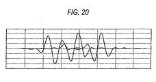
- Data transmission by a DWMC transmission system is transmitted in such a manner that an impulse response of each sub carrier is overlapped in each sub carrier as shown in Fig. 20 .
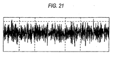
- Each transmission symbol becomes such a time wave that an impulse response of each sub carrier was combined as shown in Fig. 21 .
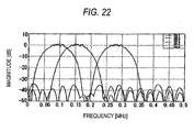
- FIG. 22 An example of the amplitude spectrum is shown in Fig. 22 .
- the DWMC transmission system approximately tens of ⁇ hundreds of transmission symbols of Fig. 20 are collected to configure one transmission frame.
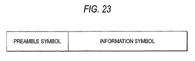
- a configuration example of a DWMC transmission frame is shown in Fig. 23 .
- this DWMC transmission frame in addition to an information data transmission symbol, a preamble symbol etc., which are used for carrier detection, synchronization, equalization and so on, are included.
- a conceptual configuration of a power line communication apparatus in case that the DWMC transmission system was adopted is shown in Fig. 19 . Firstly, in a transmitting device 299, bit data is converted into symbol data by a symbol mapper 210, and in accordance with each symbol data, symbol mapping (PAM) is carried out.
- PAM symbol mapping
- a sample value of a time axis waveform is generated, and a sample value sequence, which represents a transmission symbol, is generated.
- a D/A converter 240 it is converted from this sample value sequence to a base band analog signal waveform, which is continued in terms of time, and transmitted.
- a reception signal is converted into a digital signal in an A/D converter 310, and wavelet-converted so as to be able to handle phase information in a complex wavelet converter 320, and in a carrier detector 330, presence or absence of the reception signal is detected, and in a synchronous circuit 340, synchronizing timing is extracted from the reception signal, and in an equalizer 350, the reception signal is compensated so as to cancel influence of a transmission path, and in a transmission path estimator 370, a state of a power line transmission path is estimated, and in a judging unit 380, the reception signal is judged by use of a threshold level.
- the number of pieces of the sample values on a time axis, which are generated by inverse wavelet conversion is normally 2 n (n is a positive integer) pieces.
- This invention is to provide a communication apparatus which solves the above-described problem, and which sufficiently takes hold of a power line transmission path characteristic, and which follows to various transmission path fluctuation, and which can heighten transmission efficiency.
- This invention is a communication apparatus which carries out multi-carrier modulation processing according to claim 1.
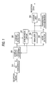
- Fig.1 is a block diagram which shows a receiving device in an embodiment 1 of this invention.
- a transmitting device is the same as the transmitting device 299 of Fig.19 , as to which an explanation was carried out in the conventional technology.
- 310 designates an A/D converter which converts an analog signal into a digital signal
- 320 designates a complex wavelet converter which generates a in-phase signal and an orthogonal signal by wavelet-converting a reception signal
- 330 designates a carrier detector for detecting a transmission signal which is transmitted from a transmitting device
- 340 designates a synchronous circuit for synchronizing with the reception signal
- 350 designates an equalizer for compensating a signal which was distorted by influence of a transmission path
- 360 designates a noise detector which detects presence or absence of narrow-band noise in each sub carrier band, by use of a signal after complex wavelet conversion
- 370 designates a transmission path estimator which determines primary modulation which is used in each sub carrier of a symbol mapper in a transmitting device, by use of a signal which is outputted from the equalizer 350 and information of presence or absence of narrow-band noise which is outputted from the noise detector
- 380 designates a judging unit which
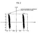
- Fig. 2 is a view which shows a scatter of an equalizer output signal
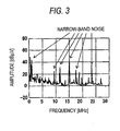
- Fig. 3 is a view which shows a noise characteristic in a power line transmission path.
- a reception signal is converted from an analog signal into a digital signal in the A/D converter 310, and in the complex wavelet converter 320, a digital signal, which was received, is wavelet-converted, and in the carrier detector 330, a signal, which is transmitted from the transmitting device, is detected, and in the synchronous circuit 340, wavelet conversion timing is adjudted of the complex wavelet converter 320, so as to be synchronized with a reception signal by use of a preamble signal, and in the equalizer 350, influence of a transmission path is removed, and in the noise detector 360, narrow-band noise, which exists in a use band, is detected, and in the transmission path estimator 370, a state of a transmission path is estimated, and a primary modulation system of a symbol mapper which is used in the transmitting device is determined, and in the judging unit 380, judgment is carried out by use of a signal which is outputted from the equalizer 350.
- Fig.2 shows a scatter (all sub carrier portions) of an equalizer output of the receiving device in case that all sub carriers 2PAM were selected in the symbol mapper of the transmitting device.
- CINR Carrier power to (Interference-plus-Noise) power Ratio
- primary modulation e.g., 16PAM, 8PAM etc.
- This is transmission path estimation which is normally carried out in the transmission and receiving device.
- a communication system of this invention was applied to power line communication
- a band which can be used 2MHz to 30MHz
- Fig.3 shows a noise characteristic in a band which is used for the power line communication. Since this band is used for amateur radio and short wave broadcasting etc., in addition to the power line communication, those existing systems exist as narrow-bandnoise to the power line communication, as shown in Fig.3 .
- these narrow-band noises exist on a steady basis, since CINR is deteriorated in a certain sub carrier at the time of transmission path estimation, it is possible to deal with, by making a sub carrier, which is using the same band as that band, non-use.
- noise detection is carried out by the noise detector 360.
- this detection result is also used as information for estimation by the transmission path estimator 370.
- the way to deetct noise detection is concretely explained.
- wavelet conversion is carried out, and when an output in each sub carrier is measured, as shown in Fig.3 , signals including narrow band noise are outputted from the complex wavelet converter 320.
- the noise detector 360 obtains an average value, median or the like of all sub carriers, checks a sub carrier, which has a large value of for example, 12dB or more, detects such sub carrier as "having narrow band noise" and transfers this information to the transmission path estimator 370. In case that the system becomes unstable, the transmission path estimator inhibits to use of the sub carrier which was checked here.
- the communication apparatus of the present invention is explained as the power line communication.
- the power line communication is one example of the transmission line which causes irregularly the narrow band noises.
- the present invention is not limited to the power line communication.
- the complex wavelet converter 320 is used, but a communication apparatus of this invention is not restricted to this, and it is possible to apply to such a wavelet converter that a phase of each sub carrier can be confirmed.
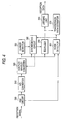
- Fig, 4 is a block diagram which shows a receiving device in an embodiment 2 of this invention. In passing, a transmitting device is the same as the transmitting device 299 of Fig.19 .
- a difference between the receiving devices of Fig.4 and of Fig.1 is only an AGC (Automatic Gain Control) circuit 390. Since other circuits are the same as the circuits which were explained in Fig.1 , descriptions are pursuant to the descriptions in the embodiment 1.
- 390 designates an AGC circuit which automatically adjust a gain of a reception signal.
- Fig. 4 and Fig. 5 an operation in case that this system was applied to the power line communication will be described.
- Fig.5 is a view which shows a noise characteristic in case that wide-band noise was added in a power line transmission path.
- a difference from the embodiment 1 is to carry out noise detection by the noise detector 360 including a gain which is used by the AGC circuit.
- Fig. 5 shows an amplitude spectrum of a power line transmissionpathbypresence or absence of an electric equipment which continuously generates impulse noise of a high level in a time axis.
- the noise detector 360 considering that a system has becomes unstable due to random wide-band noise when wide-band noise exists by an output from the AGC circuit 390 and retransmission occurs frequently in normal transmission path estimation, mitigates a threshold value which is used for transmission path estimation and transmission path estimation is carried out at a plurality of times, and, in that state, determines primary modulation of each sub carrier by using a minimum CINR value in each sub carrier. By doing in this manner, even under a power line communication transmission path in which various noises exist, it becomes possible to carry out good communication.
- a transmission path estimator in an embodiment 3 of this invention will be described.
- a receiving device, and a transmitting device of a communication apparatus are the same as in the embodiment 1 or 2.
- Fig.7 shows a frame configuration view in case of carrying out transmission path estimation by use of time of a power supply cycle.
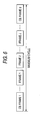
- Fig. 6 shows a frame configuration view for explaining an operation of a normal transmission path estimator.
- a transmission path estimation frame is added in a frame to be transmitted and received (in the figure, a "CE frame” is the “transmission path estimation frame”).
- this transmission path estimation frame is used again on an irregular basis, when a transmission path fluctuates significantly, and if a past transmission path estimation result is used, many errors will be generated, and as a result, it comes to be in such a state that retransmission occurs frequently.
- the transmission path estimator 370 in the embodiment 3 of this invention carries out an operation of transmission path estimation for a power supply cycle 1 cycle portion, for example, by use of a transmission path estimation frame continuously during a period of a power supply cycle.
- the transmission path estimator 370 which is used in a communication apparatus in an embodiment 4 of this invention, will be described.
- transmission path estimation is carried out in a certain cycle.
- the transmission path estimator 370 in this embodiment in case that, at that time, fluctuation of noise and fluctuation of a transmission path exist in 1 cycle, but in each sub carrier, influence of transmission path fluctuation is smaller than a threshold value (in case that it does not have influence on errors), becomes to maintain good transmission efficiency by use of that sub carrier even if there is fluctuation.
- a transmission path estimator in an embodiment 5 of this invention will be described.
- FIG.8 A block diagram of a receiving device in the embodiment 5 of this invention is shown in Fig.8 .
- the transmitting device 299 is to use the same thing as in Fig.19 .
- a point on which this embodiment is different from a conventional system is such a point that a judgment signal from the judging unit 380 is inputted to the transmission path estimator 370.
- transmission path estimation is carried out once, and next transmission path estimation will be carried out in case that a transmission path fluctuated significantly, and in case that it exceeded maximum time of a cycle for carrying out transmission path estimation, and so on. It is normal to use an exclusive use frame as a transmission path estimation frame in this case.
- transmission efficiency is deteriorated depending on the number of transmission path estimations.
- the transmission path estimator 370 and the judging unit 380 as a circuit configuration of a judgment feed-back type, in CINR which is obtained at the time of transmission path estimation, dispersion froma judgment value in each sub carrier is obtained as CINR, and thereby, transmission path estimation is to carried out not only in a transmission path estimation frame but also in a normal data frame.
- Fig.9 is a frame configuration view in case of carrying out transmission path estimation by use of a transmission path estimation exclusive use frame and a data frame.
- a transmission path estimator which is used in a communication apparatus in an embodiment 6 of this invention, will be described.
- a configuration of a communication apparatus used is the configuration of the communication apparatus of the embodiment 5.
- a transmission path estimator carries out averaging in a form which is as follows.
- a transmission path estimator 370 can complete transmission path estimation in 1 frame, if symbol number necessary for transmission path estimation is entered in 1 frame which is received by a receiving device.
- a transmission path estimator 370 of a communication apparatus in an embodiment 7 of this invention will be described.
- a block configuration of the communication apparatus of this embodiment used is the block configuration of the communication apparatus which was described in the conventional system as shown in Fig.19 or in the embodiment 5.
- judgment data of a judgment feed-back type is used in a data frame, as to the pseudo data here, it is convenient to fix a mluti-value level, and it is good to use a minimum multi-value level (e.g., 2PAM) from the viewpoint of a resistance property.
- a minimum multi-value level e.g., 2PAM
- Atransmissionpath estimator of a communication apparatus in an embodiment 8 of this invention will be described.
- a block configuration of the communication apparatus of this embodiment used is the block configuration of the communication apparatus which is described in the embodiment 1, 2 or 5, and as an operation of the transmission path estimator 370, transmission path estimation is carried out at a plurality of times.
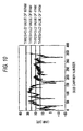
- Transmission path estimation of the transmission path estimator 370 is carried out by measuring CINR in each sub carrier in a reception signal, but since a transmission path fluctuates periodically or non-periodically, in case of a transmission path such as a power line, in case that transmission path estimation was carried out at a plurality of times, a transmission path estimation value of each sub carrier shows almost the same value, and fluctuates significantly.
- Fig.10 is a graph which shows CINR in case that there was almost no transmission path fluctuation in case that transmission path estimation was carried out at a plurality of times.
- the transmission path estimator 370 uses a maximum value in each sub carrier as an initial value, to a result which was obtained by transmission path estimations at a plurality of times, and uses a median in case that retransmission from the transmitting device 299 becomes to occur at many times, and uses a minimum value if communication does not become stable.
- a block configuration of the communication apparatus in this embodiment is the same block configuration as that described in the embodiment 8.
- As a transmission path for which the transmission path estimator 370 estimates, considered is almost the same transmission path as the transmission path which was considered in the embodiment 8.
- a threshold value which is used when a primary modulation system to be used in a symbol mapper of a transmitting device from CINR which was obtained by transmission path estimation, a value which is set up in the beginning becomes improper.
- the transmission path estimator 370 in this embodiment controls in such a manner that transmission efficiency in an entire system including retransmission etc. is improved, by changing setup of each threshold value higher (i.e. by setting them to have a margin). This is because there is such a case that, depending on a distribution of CINR, transmission efficiency is changed significantly by simply changing a threshold value. By the suchlike configuration, it becomes possible to further heighten transmission efficiency, more than that of the communication apparatus in the embodiment 8.
- the transmission path estimator 370 of a communication apparatus in an embodiment 10 of this invention will be described.
- considered is a transmission path which is almost the same as the transmission path which was considered in the embodiment 8.
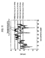
- a transmission path characteristic fluctuates significantly, in case that a plurality of transmission path estimation results, which were obtained, were viewed.
- Fig.11 shown is a graph which shows CINR in case that there is transmission path fluctuation in case that transmission path estimation was carried out at a plurality of times.
- every time transmission fluctuation occurs errors are increased, depending on its range, and there is such a possibility that, even if error correction is carried out, a frame at that time becomes to be retransmitted.
- the transmission path estimator 370 in this embodiment on the basis of the above-described knowledge, can control in such amanner that transmission efficiency in an entire system including retransmission etc. is improved, by making non-use to such a sub carrier that its fluctuation is large, to CINR which was obtained in each sub carrier, or by reducing retransmission by selecting a minimum value in results which were obtained.
- the transmission path estimator 370 of a communication apparatus in an embodiment 11 of this invention will be described.
- considered is a transmission path which is almost the same as the transmission path which was considered in the embodiment 10.
- the transmission path estimator 370 in this embodiment is designed to carry out transmission path estimation 2 times with timing which is not synchronized with a power supply cycle or its half cycle, to a transmission path estimation request, and to select a value in which CINR is larger, in each sub carrier, by utilizing a transmission path estimation result which was obtained.
- the transmission path estimator 370 in this embodiment is designed to carry out transmission path estimation 2 times with timing which is not synchronized with a power supply cycle or its half cycle, to a transmission path estimation request, and to select a value in which CINR is larger, in each sub carrier, by utilizing a transmission path estimation result which was obtained.
- the transmission path estimator 370 of a communication apparatus in an embodiment 12 of this invention will be described. In this embodiment, considered is a transmission path which is almost the same as the transmission path which was considered in the embodiment 10.
- Fig.23 is a view which shows a configuration example of an inside of a transmission frame in a DWMC transmission system.
- a frame configuration of a reception signal is transmitted by a frame which is composed of a preamble signal necessary for synchronization and equalization processing and a signal for information as in Fig.23 .
- condition of a power line transmission path changes vary slowly, as compared to a wireless transmission path.
- instantaneous fluctuation it is generated by ON/OFF of an electric equipment, and soon.
- transmission path fluctuation which was synchronized with a power supply, and so on, are also conceivable.
- the transmission path estimator 370 in this embodiment is enough if it carries out transmission path estimation in a manner of a long cycle (at an interval from second to minute), to very slow transmission path fluctuation, and has a necessity to carry out re-transmission path estimation since a transmission path state changes significantly, to instantaneous fluctuation due to ON/OFF of an electric equipment.
- the transmission path estimator 370 of a communication apparatus in an embodiment 13 of this invention will be described.
- a block configuration of a communication apparatus used is the block configuration of the communication apparatus of the conventional system of Fig. 19 or the embodiment 1 or 2.
- CINR is obtained, and primary modulation, which is used in a symbol mapper of a transmitting device, is determined, and each parameter is set up so as to transmit with maximum efficiency in a transmission path through which communication is carried out.
- the communication apparatus of this embodiment carries out an operation as follows, on the basis of the above-described knowledge.
- the transmission path estimator 370 in case that a transmission path itself is not congested and in case that an amount of data to be transmitted is smaller than transmission path capacity (capacity which was obtained by transmission path estimation), is operated so as to lower by 1 rank (e.g., from 4PAM to 2PAM), to a multi-value level which is judged in the vicinity of a threshold value, or to give a margin (e.g., 2dB) to all threshold values, or further, to determine a multi-value level by use of a minimum value in case that transmission path estimation is carried out at a plurality of times.
- 1 rank e.g., from 4PAM to 2PAM
- a multi-value level which is judged in the vicinity of a threshold value or to give a margin (e.g., 2dB) to all threshold values, or further, to determine a multi-value level by use of a minimum value in case that transmission path estimation is carried out at a plurality of times.
- this system is applicable not only to the wavelet conversion, but also to muti-carrier communication which realizes another low side lobe spectrum, by use of OFDM/OQAM (in this case, a multi-value level is MQAM: M is a multi-value number), Filtered OFDM, Filterred Mutitone systems etc.
- this system is also applicable to a FFT (Fast Fourier Transform) based multi-carrier communication system in which a characteristic is deteriorated but which has been often used since old times.
- FFT Fast Fourier Transform
- the transmission path estimator 370 of a communication apparatus in an embodiment 14 of this invention will be described.
- CINR is obtained, and primary modulation, which is used in a symbol mapper of a transmitting device, is determined, and each parameter is set up so as to transmit with maximum efficiency in a transmission path through which communication is carried out.
- the transmission path estimator 370 of this embodiment carries out an operation as follows, on the basis of the above-described knowledge.
- this system is applicable not only to the wavelet conversion, but also to multi-carrier communication which realizes another low side lobe spectrum, by use of OFDM/OQAM (in this case, a multi-value level is MQAM: M is a multi-value number), etc.
- this system is also applicable to a FFT (Fast Fourier Transform) based multi-carrier communication system (for example, ADSL, 802.11a and g) in which a characteristic is deteriorated but which has been often used since old times.
- FFT Fast Fourier Transform
- the transmission path estimator 370 of a communication apparatus in an embodiment 15 of this invention will be described.
- a block configuration of a communication apparatus used is the block configuration of the communication apparatus of the conventional system of Fig.19 or the embodiment 1 or 2.
- demodulation processing is carried out in a receiving device, in synchronization with a reception signal, but it does not mean that synchronization is realized to all sub carriers.
- a sub carrier which can be used, is limited to, for example, only a sub carrier which has an even number.
- Fig.22 is a view which shows a transmission spectrum example in a DWMC transmission system.
- the transmission path estimator 370 of a communication apparatus in an embodiment 16 of this invention will be described.
- a block configuration of a communication apparatus used is the block configuration of the communication apparatus of the conventional system of Fig.19 of the embodiment 1 or 2.
- the transmission path estimator 370 in this embodiment carries out an operation as follows.
- the transmission path estimator 370 of a communication apparatus in an embodiment 17 of this invention will be described.
- a block configuration of a communication apparatus used is the block configuration of the communication apparatus of the conventional system of Fig.19 or the embodiment 1 or 2.
- output power of the transmitting device 299 is smaller than maximum power, or maximum power required by the law.
- the communication apparatus in case that it did not satisfy a desired transmission speed in case that transmission path estimation was carried out by a normal method, calculates how much gain of an amplifier of the transmitting device has to be increased so as to realize the desired transmission speed, by use of a transmission path estimation result at that time, and on the basis of that calculation result, controls transmission power of the transmitting device 299.
- a sub carrier which is using the same band as a band which is used by a partial existing system (e.g., amateur radio etc.), is made to be of non-use since it becomes an obstacle to a existing system.
- a partial existing system e.g., amateur radio etc.
- Fig.12 is a view of an amplitude spectrum in a DWMC transmission system.
- Fig.12 shows an amplitude spectrum in such a case that a sub carrier, which is using the same band as a band which is used by amateur radio, was made non-use. As shown in Fig.12 , it shows that, by simply making several pieces of sub carriers non-use, a notch of 30dB or more is formed.
- Wavelet based sub carrier is of a low side lobe amplitude spectrum.
- Fig.22 shown is a transmission spectrum example in the DWMC transmission system.
- a first side lobe of an amplitude spectrum of a sub carrier which is used here is -35dB.
- transmission power is increased, a side lobe of each sub carrier is lifted together, and therefore, interference to an existing system increases.
- the transmission path estimator 370 in this embodiment so as for the notch to become deeper only by such a portion that a gain of an amplifier of the transmitting device 299 was increased, further makes a sub carrier non-use in the vicinity of them.
- an increase amount of a gain of an amplifier of the transmitting device 299 and the number of sub carriers which are made non-use are determined uniquely.
- the transmission path estimator 370 of a communication apparatus in an embodiment 18 of this invention will be described.
- a block configuration of a communication apparatus used is the block configuration of the communication apparatus of the conventional system of Fig.19 or the embodiment 1 or 2, and to a transmission path estimation request, transmission path estimation is assumed to be carried out at a plurality of times.
- a dynamic range of a receiving device is assumed to be 40dB.
- the number of all sub carriers is assumed to be 300.
- a transmission path is a static transmission path and does not move.
- a noise level of a transmission path is measured.
- the noise level is easily obtained by use of a coefficient of an equalizer and a gain of AGC.
- SNR signal power to noise power ratio
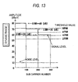
- Fig.13 is a pattern diagram of a received signal reveal.
- Fig.13 shows a noise level at the time of no reception signal, a signal level received by a receiving device when a transmitting device sent a signal with maximum power, and CINR which is obtained at the time of transmission path estimation.
- a transmitting device outputted with maximum power a receiving device is receiving with maximum 80dB ⁇ V, minimum 60dB ⁇ V.
- CINR which is obtained at the time of transmission path estimation, becomes maximum 40dB, minimum 20dB, since a dynamic range of the receiving device is 40dB.
- SNR of a transmission path it is 60dB ⁇ V at the minimum, but as to CINR, it is simply 20DB.
- the transmission path estimator 370 of a communication apparatus in an embodiment 19 of this invention will be described. It is assumed that a block configuration of a communication apparatus in this embodiment is the same block configuration of the communication apparatus as in the embodiment 18.
- the transmission path estimator 370 obtains SNR of a transmission path at the time of transmission path estimation, in the same manner as in the embodiment 18. Calculated is how much a gain can be lowered by, in each sub carrier, in order to realize a maximum transmission speed and minimum transmission power by use of SNR which was obtained in each sub carrier.
- a multi-value level which is used in each sub carrier, or information, which corresponds to it, is informed from a receiving device to the transmitting device 299, at the time of transmission path estimation.
- a transmitting device carries out primary modulation of each sub carrier by use of information of a multi-value level, and controls transmission power of each sub carrier by use of the gain information.
- the transmission path estimator 370 of a communication apparatus in an embodiment 20 of this invention will be described.
- a block configuration of a communication apparatus used is the block configuration of the communication apparatus of the conventional system of Fig.19 or the embodiment 1 or 2.
- the transmission path estimator 370 is designed to carry out transmission path estimation at a plurality of times to a transmission path estimation request.
- a transmission path is a static transmission path and does not move.
- normal transmission path estimation (a transmitting device makes transmission with maximum power) is carried out. From a transmission path estimation result in a receiving device, only a gain of a sub carrier, which showed a maximum multi-value level, is lowered by only a in a single uniform way.
- a is obtained from a difference of threshold values which are used at the time of determining a multi-value level. Also here, for ease of explanation, a use multi-value level is set to 16PAM ⁇ 2PAM, and a difference of each threshold value is se to 6dB in a single uniform way. Here, a is 6dB.
- a first time transmission path estimation result is informed to the transmitting device 299 by a multi-value level or information which corresponds to it, and such a fact that a second time transmission path estimation will be carried out is also informed at the same time.
- the transmitting device 299 lowers a gain of only a sub carrier of the maximum multi-value level (here, 16PAM) by only 6dB to transmit, and in a receiving device, the second transmission path estimation is carried out, and comparing with a first time result, if a transmission speed is lowered, transmission path estimation is finished at the second time, and the last (here, first time) transmission path estimation result is informed to the transmitting device 299 as a result to this time's transmission path estimation request.
- a sub carrier of the maximum multi-value level here, 16PAM
- third time transmission path estimation is carried out.
- the transmitting device 299 lowers a gain of only a sub carrier of the maximum multi-value level by only 6dB, to transmit, and in the receiving device, third time transmission path estimation is carried out.
- the transmitting device 299 lowers a gain of a sub carrier whose gain is lowered at both the first, second time, by only its sum 12dB.
- N-th time transmission path estimation when N-th time transmission path estimation is carried out, used are a transmission path estimation result which was obtained at (N-1)-th time and accumulated gains. Similar calculation is repeated until a transmission speed comes down, and at such a time point that the transmission speed came down, transmission path estimation is stopped, and the last result is used as a final result.
- a concrete example will be described by use of Figs. 13 , 15 ⁇ 17 .
- Fig.15 is a pattern diagram of a level of a signal which is received at the time when gains of sub carriers up to sub carrier numbers 1 ⁇ 100 were lowered by only 6dB
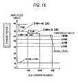
- Fig.16 is a pattern diagram of a level of a signal which is received at the time when gains of sub carriers up to sub carrier number 101 ⁇ 200 were lowered by only 6dB
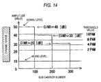
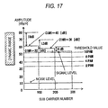
- Fig. 17 is a pattern diagram of a level of a signal which is received at the time when gains of sub carriers up to sub carrier number 1 ⁇ 100 were lowered by 18dB, and gains of sub carriers up to sub carrier number 101 ⁇ 200 are lowered by 12dB, and gains of sub carriers up to sub carrier number 201 ⁇ 300 are lowered by only 6dB.
- Fig.13 is a pattern diagram of a level of a signal which was received.
- a transmitting device outputted with maximum power from Fig.13 a receiving device can receive with maximum 80dB ⁇ V, minimum 60dB ⁇ V.
- a CINR value which is obtained at the time of transmission path estimation, becomes maximum 40dB, minimum 20dB, since a dynamic range of the receiving device is 40dB.
- gains of sub carriers up to sub carrier number 1 ⁇ 100 which are selecting the maximum multi-value level (here, 16PAM), are lowered by 6dB.
- CINR becomes 40dB, 36dB, 26dB.
- gains of sub carriers up to sub carrier number 1 ⁇ 200, which selected 16PAM is lowered by 12dB, 6dB.
- CINR becomes 40dB, 36dB, 32dB.
- all sub carriers become to select 16PAM.
- gains are lowered by 18dB, 12dB, 6dB.
- 16PAM is selected in all sub carrier in the same manner as in the third time.
- a forth time's transmission speed and a third time' s transmission speed become the same, processing is finished, and a third time's result is used for communication as a transmission path estimation result at this time.
- a third time's speed and a fourth time's speed become the same by accident, but since an actual transmission path characteristic is complex, there is generally no case that they become the same.
- this processing is continued until such time that a transmission speed is deteriorated, and at such a time point that the speed was deteriorated, the last result is to be used as a transmission path estimation result at that time.
- a gain of the transmitting device 299 was controlled by use of the CINR value, but it is also possible to carry out power control of the transmitting device 299 by use of SNR of each sub carrier.
- the transmission path estimator 370 of a communication apparatus in an embodiment 21 of this invention will be described.
- a block configuration of a communication apparatus used is the block configuration of the communication apparatus of the conventional system of Fig.19 or the embodiment 1 or 2.
- transmission path estimation is carried out at a plurality of times, and at that time, a reception signal level is also measured (noise level measurement is unnecessary). It is assumed that a reception level at the time of first transmission path estimation is (a) of Fig.18 . Out of all sub carriers, a MAX level is extracted, and an offset level is set up, and a gain of a sub carrier, which is received with a level of (MAX level - offset level) or more, is lowered by only B in a single uniform way. Next, second time transmission path estimation is carried out, and a transmission speed is compared with that of the first time, and if a transmission speed has been deteriorated, the last result of CINR and gain information are used as a transmission path estimation result.
- Fig.18 is a pattern diagram of a transmission path estimation characteristic in such a case that a dynamic range is insufficient.
- CINR may be determined by second time processing.
- a block configuration of a communication apparatus in an embodiment 22 of this invention used is the block configuration of the communication apparatus of the conventional system of Fig.19 or the embodiment 1 or 2.
- FIG.26 is a view which shows the frame configuration example of the communication apparatus in the embodiment 22 of this invention.
- this frame configuration shows data which is transmitted toward a receiving device, on the basis of information which the transmitting device 299 obtained from the transmission path estimator 370 of a receiving device.
- PRE shows a preamble signal which is used in synchronization processing, equalization processing etc. of a receiving device
- SYNC shows a SYNC signal which identifies a data start
- TMI shows a signal which shows information based upon a transmission path estimation result
- FC shows a frame control signal
- PL shows an information signal.
- the information which is based upon a transmission path estimation result of TMI may be a result itself which was estimated by the transmission path estimator 370 of a receiving device, or information which defines modulation and demodulation, which are used in transmission and reception, on the basis of estimation.
- a control signal PRE and SYNC
- transmission path estimation information is placed at a forefront portion of the information signal.
- SYNC SYNC
- FC1 FC1.
- the high gain diversity processing is desired to be carried out to the TMI signal, only at such time that transmission path estimation was carried out, detailed transmission path estimation result information is exchanged in a communication apparatus as the information signal, and that information is stored in a memory etc., and in a normal communication state, transmitted is only information (INDEX etc.) from which a location, in which that information is stored, is known.
- a transmission path it is not limited to a transmission path of a power line, and it is possible to apply to a digital communication apparatus etc. which utilizes a power line as a transmission path.
- a communication apparatus which relates to this invention, becomes possible to follow sufficiently to various fluctuations of a transmission path such as a power line, and as a power line communication apparatus, or by applying to a high speed communication apparatus of another transmission path, it is useful.
- This invention is to provide a communication apparatus which solves the above-described problem, and which sufficiently takes hold of a power line transmission path characteristic, and which follows to various transmission path fluctuation, and which can heighten transmission efficiency.
Landscapes
- Engineering & Computer Science (AREA)
- Signal Processing (AREA)
- Computer Networks & Wireless Communication (AREA)
- Power Engineering (AREA)
- Cable Transmission Systems, Equalization Of Radio And Reduction Of Echo (AREA)
Description
- This invention relates to a communication apparatus and a communication method using multi-carrier transmission system, particularly, to a communication apparatus and a communication method which used a multi-carrier transmission system (Digital Wavelet Multi Carrier transmission system, hereinafter, referred to as DWMC transmission system) which carries out data transmission by digital modulation and demodulation processing which used a real coefficient wavelet filter bank which is more suitable for a power line transmission path and a transmission path such as a telephone line.
-
WO 98/10545 A1 -
WO 98/10545 A1 - As a conventional technology which has been frequently used in the multi-carrier transmission system, there are FFT (Fast Fourier Transform) based OFDM (Orthogonal Frequency Division Multiplexing) and Wavelet based OFDM. Such an example that these technologies were applied to power line communication is disclosed in (
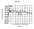
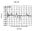
JP-A-11-163807 Fig. 20 . Each transmission symbol becomes such a time wave that an impulse response of each sub carrier was combined as shown inFig. 21 . An example of the amplitude spectrum is shown inFig. 22 . In the DWMC transmission system, approximately tens of ∼ hundreds of transmission symbols ofFig. 20 are collected to configure one transmission frame. A configuration example of a DWMC transmission frame is shown inFig. 23 . In this DWMC transmission frame, in addition to an information data transmission symbol, a preamble symbol etc., which are used for carrier detection, synchronization, equalization and so on, are included. A conceptual configuration of a power line communication apparatus in case that the DWMC transmission system was adopted is shown inFig. 19 . Firstly, in atransmitting device 299, bit data is converted into symbol data by asymbol mapper 210, and in accordance with each symbol data, symbol mapping (PAM) is carried out. And, in a serial-parallel converter 220, a real value di (i=1∼M) is given with respect to each sub carrier, and in an inversewavelet conversion part 230, inverse wavelet conversion is carried out on a time axis. By this, a sample value of a time axis waveform is generated, and a sample value sequence, which represents a transmission symbol, is generated. In a D/A converter 240, it is converted from this sample value sequence to a base band analog signal waveform, which is continued in terms of time, and transmitted. In areceiving device 399, a reception signal is converted into a digital signal in an A/D converter 310, and wavelet-converted so as to be able to handle phase information in acomplex wavelet converter 320, and in acarrier detector 330, presence or absence of the reception signal is detected, and in asynchronous circuit 340, synchronizing timing is extracted from the reception signal, and in anequalizer 350, the reception signal is compensated so as to cancel influence of a transmission path, and in atransmission path estimator 370, a state of a power line transmission path is estimated, and in ajudging unit 380, the reception signal is judged by use of a threshold level. Here, the number of pieces of the sample values on a time axis, which are generated by inverse wavelet conversion, is normally 2n (n is a positive integer) pieces. - In the meantime, in a conventional system, there was such a problem that transmission path estimation, which is carried out in a receiving device, can not follow sufficiently to instantaneous fluctuation and periodical fluctuation of wide-band noise or narrow-band noise, or instantaneous fluctuation and periodical fluctuation which come up with amplitude fluctuation and phase fluctuation of a transmission path itself, when transmission path estimation is simply carried out only once in a certain cycle, in a power line transmission path. Here, as one example of the power line transmission path, an attenuation characteristic of the power lien transmission path is shown in
Fig.24 . In addition,Fig.25 is a view which shows a group delay characteristic of the power line transmission path. - As described above, in a multi-carrier power line communication apparatus which used the conventional wavelet, it has such a problem that transmission path estimation, which is carried out in a receiving device, can not follow sufficiently to instantaneous fluctuation and periodical fluctuation of wide-band noise or narrow-band noise, or instantaneous fluctuation and periodical fluctuation which come up with amplitude fluctuation and phase fluctuation of a transmission path itself, when transmission path estimation is simply carried out only once in a certain cycle, in a power line transmission path. In this power line communication apparatus, it is requested to sufficiently take hold of a transmission path state, and to heighten transmission efficiency.
- This invention is to provide a communication apparatus which solves the above-described problem, and which sufficiently takes hold of a power line transmission path characteristic, and which follows to various transmission path fluctuation, and which can heighten transmission efficiency.
- This invention is a communication apparatus which carries out multi-carrier modulation processing according to
claim 1. - By this, it becomes possible to sufficiently follow to various fluctuations of a transmission line such as a power line transmission path, and as a result, it becomes possible to heighten transmission efficiency.
-
-
Fig.1 is a block diagram which shows a receiving device in anembodiment 1 of this invention. -
Fig. 2 is a view which shows a scatter of an equalizer output signal. -
Fig.3 is a view which shows a noise characteristic in a power line transmission path. -
Fig.4 is a block diagram which shows a receiving device in anembodiment 2 of this invention. -
Fig. 5 is a view which shows a noise characteristic in such a case that wide-band noise was added in a power line transmission path. -
Fig.6 is a frame configuration view for explaining an operation of a normal transmission path estimator. -
Fig.7 is a frame configuration view in such a case that transmission path estimation is carried out by use of time of a power supply cycle. -
Fig.8 is a block diagram of a receiving device in anembodiment 5 of this invention. -
Fig.9 is a frame configuration view in such a case that transmission path estimation is carried out by use of a transmission path estimation exclusive use frame and a data frame. -
Fig.10 is a graph which shows CINR in such a case that there was almost no transmission path fluctuation in case that transmission path estimation was carried out at a plurality of times. -
Fig.11 is a graph which shows CINR in such a case that there is transmission path fluctuation in case that transmission path estimation was carried out at a plurality of times. -
Fig.12 is a view of an amplitude spectrum in a DWMC transmission system. -
Fig.13 is a pattern diagram of a level of a signal which was received. -
Fig.14 is a pattern diagram at the time when a gain of an amplifier of a transmitting device was lowered by only 30dB. -
Fig.15 is a pattern diagram of a level of a signal which is received at the time when gains of sub carriers up tosub carrier number 1∼100 were lowered by only 6dB. -
Fig.16 is a pattern diagram of a level of a signal which is received at the time when gains of sub carriers up tosub carrier number 1∼100 were lowered by 12dB, and gains of sub carriers up to sub carrier number 101∼200 were lowered by only 6dB. -
Fig.17 is a pattern diagram of a level of a signal which is received at the time when gains of sub carriers up tosub carrier number 1∼100 were lowered by 18dB, and gains of sub carriers up to sub carrier number 101∼200 were lowered by 12dB, and gains of sub carriers up to sub carrier number 201∼300 were lowered by only 6dB. -
Fig.18 is a pattern diagram of a transmission path estimation characteristic in such a case that a dynamic range is insufficient. -
Fig.19 is a view which shows a power line communication apparatus in a conventional system. -
Fig.20 is a view which shows a wavelet waveform example. -
Fig.21 is a view which shows a transmission waveform example in the DWMC transmission system. -
Fig.22 is a view which shows a transmission spectrum example in the DWMC transmission system. -
Fig.23 is a view which shows a configuration example of an inside of a transmission frame in the DWMC transmission system. -
Fig. 24 is a view which shows an attenuation characteristic of a power line transmission path. -
Fig.25 is a view which shows a group delay characteristic of a power line transmission path. -
Fig.26 is a view which shows a frame configuration example of a communication apparatus in an embodiment 22 of this invention. - Hereinafter, embodiments of this invention will be described with reference to
Fig.1 to Fig.18 . -
Fig.1 is a block diagram which shows a receiving device in anembodiment 1 of this invention. In passing, a transmitting device is the same as the transmittingdevice 299 ofFig.19 , as to which an explanation was carried out in the conventional technology. - In
Fig.1 , 310 designates an A/D converter which converts an analog signal into a digital signal, and 320 designates a complex wavelet converter which generates a in-phase signal and an orthogonal signal by wavelet-converting a reception signal, and 330 designates a carrier detector for detecting a transmission signal which is transmitted from a transmitting device, and 340 designates a synchronous circuit for synchronizing with the reception signal, and 350 designates an equalizer for compensating a signal which was distorted by influence of a transmission path, and 360 designates a noise detector which detects presence or absence of narrow-band noise in each sub carrier band, by use of a signal after complex wavelet conversion, and 370 designates a transmission path estimator which determines primary modulation which is used in each sub carrier of a symbol mapper in a transmitting device, by use of a signal which is outputted from theequalizer 350 and information of presence or absence of narrow-band noise which is outputted from the noise detector, and 380 designates a judging unit which carries out judgment by use of a signal which is outputted from theequalizer 350. - As to the receiving device which was configured in this manner, its operation will be described by use of
Fig. 1 to Fig. 3 . -
Fig. 2 is a view which shows a scatter of an equalizer output signal, andFig. 3 is a view which shows a noise characteristic in a power line transmission path. - In
Fig.1 , a reception signal is converted from an analog signal into a digital signal in the A/D converter 310, and in thecomplex wavelet converter 320, a digital signal, which was received, is wavelet-converted, and in thecarrier detector 330, a signal, which is transmitted from the transmitting device, is detected, and in thesynchronous circuit 340, wavelet conversion timing is adjudted of thecomplex wavelet converter 320, so as to be synchronized with a reception signal by use of a preamble signal, and in theequalizer 350, influence of a transmission path is removed, and in thenoise detector 360, narrow-band noise, which exists in a use band, is detected, and in thetransmission path estimator 370, a state of a transmission path is estimated, and a primary modulation system of a symbol mapper which is used in the transmitting device is determined, and in the judgingunit 380, judgment is carried out by use of a signal which is outputted from theequalizer 350. -
Fig.2 shows a scatter (all sub carrier portions) of an equalizer output of the receiving device in case that all sub carriers 2PAM were selected in the symbol mapper of the transmitting device. Generally, in case of carrying out transmission path estimation, a well-known frame is made to be transmitted from the transmitting device for the purpose of transmission path estimation, and in thetransmission path estimator 370 of the receiving device, CINR (Carrier power to (Interference-plus-Noise) power Ratio) is measured with dispersion from signal point allocation (in case of 2PAM, ±1) as a noise amount in accordance with the output from theequalizer 350. By use of CINR which was measured in each sub carrier, primary modulation (e.g., 16PAM, 8PAM etc.), which is used in each sub carrier, is selected, and informed to the transmittingdevice 299. This is transmission path estimation which is normally carried out in the transmission and receiving device. - Here, such a case that a communication system of this invention was applied to power line communication will be described. In the power line communication, as a band which can be used, 2MHz to 30MHz is being considered.
Fig.3 shows a noise characteristic in a band which is used for the power line communication. Since this band is used for amateur radio and short wave broadcasting etc., in addition to the power line communication, those existing systems exist as narrow-bandnoise to the power line communication, as shown inFig.3 . In case that these narrow-band noises exist on a steady basis, since CINR is deteriorated in a certain sub carrier at the time of transmission path estimation, it is possible to deal with, by making a sub carrier, which is using the same band as that band, non-use. In addition, if these narrow-band noise levels exist at a noise level or less, which was obtained at the time of transmission path estimation, on a steady basis, even if narrow-band noise does not exist, CINR is not deteriorated, and therefore, it does not become a problem. - However, when there is such a case that these narrow-band noises appears and disappears on an irregular basis and become larger than a noise level at the time of transmission path estimation, it becomes unstable in such a manner that there is an error or there is not an error until the time of transmission path estimation which will be carried out next, and even in case that error correction was carried out, in the worst case, there becomes such a state that a frame retransmission request has to be carried out, which results in dropping down transmission efficiency.
- For the purpose of avoiding the suchlike thing, as shown in
Fig.1 , noise detection is carried out by thenoise detector 360. In addition to the output of theequalizer 350, this detection result is also used as information for estimation by thetransmission path estimator 370. The way to deetct noise detection is concretely explained. In thecomplex wavelet converter 320, wavelet conversion is carried out, and when an output in each sub carrier is measured, as shown inFig.3 , signals including narrow band noise are outputted from thecomplex wavelet converter 320. - Here, the
noise detector 360 obtains an average value, median or the like of all sub carriers, checks a sub carrier, which has a large value of for example, 12dB or more, detects such sub carrier as "having narrow band noise" and transfers this information to thetransmission path estimator 370. In case that the system becomes unstable, the transmission path estimator inhibits to use of the sub carrier which was checked here. - In addition, by use of an output of the
complex wavelet converter 320, thecarrier detector 330, thesynchronous circuit 340, and theequalizer 350 are controlled, and in these blocks, an average value etc. are obtained through the use of values of all sub carriers, and thereby, processing is carried out. In this case, when narrow-band noise of a high level is inputted and processed in those circuits, it is conceivable that a characteristic is deteriorated to a large extent. On that account, it is possible to maintain high performance by making a sub carrier, which was checked in thenoise detector 360, non-use in these circuits. - By these configurations, in case that this system was applied to the power line communication, it is possible to mitigate influence of narrow-band noise which is received from another system, and good transmission path estimation becomes possible, and in addition, it is possible to also improve carrier detection and synchronization accuracy.
- As mentioned above, the communication apparatus of the present invention is explained as the power line communication. The power line communication is one example of the transmission line which causes irregularly the narrow band noises. Thus, the present invention is not limited to the power line communication.
- In passing, in the
embodiment 1, thecomplex wavelet converter 320 is used, but a communication apparatus of this invention is not restricted to this, and it is possible to apply to such a wavelet converter that a phase of each sub carrier can be confirmed. - In case that there occurs no phase lag in each sub carrier, it is possible to apply, such a wavelet converter by which an in-phase signal is obtained, to a communication apparatus of this invention.
-
Fig, 4 is a block diagram which shows a receiving device in anembodiment 2 of this invention. In passing, a transmitting device is the same as the transmittingdevice 299 ofFig.19 . - In addition, a difference between the receiving devices of
Fig.4 and ofFig.1 is only an AGC (Automatic Gain Control)circuit 390. Since other circuits are the same as the circuits which were explained inFig.1 , descriptions are pursuant to the descriptions in theembodiment 1. 390 designates an AGC circuit which automatically adjust a gain of a reception signal. Next, by use ofFig. 4 andFig. 5 , an operation in case that this system was applied to the power line communication will be described.Fig.5 is a view which shows a noise characteristic in case that wide-band noise was added in a power line transmission path. - A difference from the
embodiment 1 is to carry out noise detection by thenoise detector 360 including a gain which is used by the AGC circuit. - In the
embodiment 1, presence or absence of narrow-band noise can be detected, and in addition to this detection, by detecting a gain of the AGC circuit, it becomes possible to know influence of wide-band noise, which could not be known in thisembodiment 1.Fig. 5 shows an amplitude spectrum of a power line transmissionpathbypresence or absence of an electric equipment which continuously generates impulse noise of a high level in a time axis. - Concretely speaking, by turning ON an electric equipment. which generates impulse noise of a high level in a time axis, a noise level is increased in all bands (from 2MHz to 30MHz), which seem to be used in power line communication. In the suchlike case, since it is not possible to judge presence or absence of wide-band noise in the
embodiment 1, presence or absence of wide-band noise is judged by use of a gain of theAGC circuit 390, in the receiving device in thisembodiment 2. - By this system, it is possible to detect narrow-band noise and wide-band noise, and in case that it was detected, by carrying out transmission path estimation in tune with the number of retransmission etc., it becomes possible to carry out good communication in a verybadpower line communication transmission path.
- For example, even in case that there is no narrow-band noise, which makes a sub carrier, in which narrow-band noise exists on an irregular basis, non-use, the
noise detector 360, considering that a system has becomes unstable due to random wide-band noise when wide-band noise exists by an output from theAGC circuit 390 and retransmission occurs frequently in normal transmission path estimation, mitigates a threshold value which is used for transmission path estimation and transmission path estimation is carried out at a plurality of times, and, in that state, determines primary modulation of each sub carrier by using a minimum CINR value in each sub carrier. By doing in this manner, even under a power line communication transmission path in which various noises exist, it becomes possible to carry out good communication. - In case that this system was applied to power line communication, by a communication apparatus which is described in the
embodiment 2 of this invention, it is possible to reduce influence of narrow-band noise which is received from another system, and mitigated is influence of wide-band noise due to impulse noise of a high level at a time axis, which is emitted from an electric equipment etc., and good transmission path estimation becomes possible. - A transmission path estimator in an
embodiment 3 of this invention will be described. In this embodiment, a receiving device, and a transmitting device of a communication apparatus are the same as in theembodiment -
Fig.7 shows a frame configuration view in case of carrying out transmission path estimation by use of time of a power supply cycle. - Next, an operation will be described.
Fig. 6 shows a frame configuration view for explaining an operation of a normal transmission path estimator. - Normally, as shown in
Fig. 6 , a transmission path estimation frame is added in a frame to be transmitted and received (in the figure, a "CE frame" is the "transmission path estimation frame"). - Generally speaking, in a transmission path estimating method of the suchlike configuration, this transmission path estimation frame is used again on an irregular basis, when a transmission path fluctuates significantly, and if a past transmission path estimation result is used, many errors will be generated, and as a result, it comes to be in such a state that retransmission occurs frequently.
- Or, sinceefficiencyisbadiftransmissionpathestimation is carried out after retransmission occurs frequently, there is also such a case that certain maximum time has been determined, and transmission path estimation is carried out in tune with its cycle.
- In
Fig.6 , to instantaneous fluctuation of a transmission path, it is possible to cope with it by carrying out re-transmission path estimation, since judgment errors arise in case that it is different from a past transmission path estimation result significantly, and it results in retransmission occurring frequently, but, for example, in case that instantaneous fluctuation of a transmission path arises in synchronization with a power supply cycle (in case of 50Hz, 20ms) or its half cycle (incase of 50Hz, 10ms), if re-transmission path estimation is carried out on each occasion, transmission efficiency will be deteriorated significantly. - In order to avoid the suchlike deterioration, as shown in
Fig. 7 , thetransmission path estimator 370 in theembodiment 3 of this invention carries out an operation of transmission path estimation for apower supply cycle 1 cycle portion, for example, by use of a transmission path estimation frame continuously during a period of a power supply cycle. - As a result of that, it is possible to improve entire transmission efficiency by carrying out such things that, taking hold of which timing fluctuation due to noise and transmission path fluctuation were generated at, in that zone, it is made to not send out a signal, or it is made to lower a multi-value level of primary modulation, or frequency and time diversity is carried out to make that frame hold a resistance property.
- In addition, to fluctuation which arises at a different cycle, there is a necessity to carry out transmission path estimation in tune with the cycle. Further, it is also possible to carry out transmission path estimation randomly, but not continuously, by making such a state that total transmission path estimation time becomes nearly 1 cycle portion.
- By the suchlike configuration, for example, to fluctuation of noise and transmission path fluctuation which were synchronized with a power supply cycle, it becomes possible to make a prediction, and it becomes possible to receive and to transmit a signal effectively.
- The
transmission path estimator 370, which is used in a communication apparatus in anembodiment 4 of this invention, will be described. - In this embodiment, by use of the configuration/operation of the communication apparatus of the
embodiment 3, transmission path estimation is carried out in a certain cycle. - Further additionally, the
transmission path estimator 370 in this embodiment, in case that, at that time, fluctuation of noise and fluctuation of a transmission path exist in 1 cycle, but in each sub carrier, influence of transmission path fluctuation is smaller than a threshold value (in case that it does not have influence on errors), becomes to maintain good transmission efficiency by use of that sub carrier even if there is fluctuation. - By realizing the suchlike configuration, as compared to the communication apparatus in the
embodiment 3, it becomes possible to further heighten transmission efficiency. - A transmission path estimator in an
embodiment 5 of this invention will be described. - A block diagram of a receiving device in the
embodiment 5 of this invention is shown inFig.8 . - In passing, the transmitting
device 299 is to use the same thing as inFig.19 . - As to blocks which are being used, since blocks with the same numbers become to be of the same explanations as things which were explained in the
embodiments - A point on which this embodiment is different from a conventional system is such a point that a judgment signal from the judging
unit 380 is inputted to thetransmission path estimator 370. - Normally, as shown in
Fig. 6 , prior to communication start etc., transmission path estimation is carried out once, and next transmission path estimation will be carried out in case that a transmission path fluctuated significantly, and in case that it exceeded maximum time of a cycle for carrying out transmission path estimation, and so on. It is normal to use an exclusive use frame as a transmission path estimation frame in this case. - However, transmission efficiency is deteriorated depending on the number of transmission path estimations. Thus, in this system, by configuring the
transmission path estimator 370 and the judgingunit 380 as a circuit configuration of a judgment feed-back type, in CINR which is obtained at the time of transmission path estimation, dispersion froma judgment value in each sub carrier is obtained as CINR, and thereby, transmission path estimation is to carried out not only in a transmission path estimation frame but also in a normal data frame. -
Fig.9 is a frame configuration view in case of carrying out transmission path estimation by use of a transmission path estimation exclusive use frame and a data frame. - It is conceivable that there occurs a difference between a result of transmission path estimation which was carried out because of transmission path fluctuation at the time of communication start, and transmission path estimation which is carried out in a data frame. At this time, in case that a difference occurred with such a degree that an error is generated in a result of transmission path estimation which was measured in a transmission path estimation frame, and a result of transmission path estimation which was measured in a data frame, updating of a transmission path estimation result is requested to the transmitting
device 299 side, and thereby, a transmission path estimation result is updated. In case of updating, a result, which was obtained in the data frame, may be used. Transmission path estimation may be carried out by using an exclusive use frame again. In passing, the judgment feed back type circuit configuration of the receiving device of this embodiment is applicable also to the receiving device of theembodiment - By the suchlike configuration, it is possible to carry out transmission path estimation by use of a normal transmission path estimation exclusive use frame and a data frame, and therefore, as a result, it is possible to heighten transmission efficiency.
- A transmission path estimator, which is used in a communication apparatus in an
embodiment 6 of this invention, will be described. Here, as a configuration of a communication apparatus, used is the configuration of the communication apparatus of theembodiment 5. A point, which is different from theembodiment 5, is a transmission path estimating method by use of a data frame of thetransmission path estimator 370. - In case of carrying out transmission path estimation, required is an average of a symbol, which is a target for averaging noise, or more (the number of necessary symbols is assumed to be S). However, there is no such guarantee that each data frame is composed of S symbol or more. On that account, a unit to be averaged is set to S symbol unit, but not a frame unit, and averaging is to be continued until reaching to the S symbol, even if a frame is changed.
- Concretely speaking, a transmission path estimator carries out averaging in a form which is as follows.
- Generally, a
transmission path estimator 370 can complete transmission path estimation in 1 frame, if symbol number necessary for transmission path estimation is entered in 1 frame which is received by a receiving device. - However, if a frame, which is not for transmission path estimation but for exchanging normal data, is used for transmission path estimation, there occurs such a case that only several symbols exist in payload data.
- On that account, by use of a plurality of frames, arises a necessity to carry out 1 time transmission path estimation which corresponds to such a case that a transmission path estimation exclusive use frame was used.
- For example, assuming that 1 frame is configured of a preamble signal necessary for control of a receiving device and a payload data signal for sending information, when the number of symbols necessary for transmission path estimation is assumed to be 128, the number of symbols in payload data which is included (can be used for transmission path estimation) in a frame when communication is going on is assumed to be 8.
- In this case, a transmission path estimator becomes to be able to obtain a 128 symbol averaged transmission path estimation result (the same level as normal transmission path estimation) with 16X8=128, by receiving 16 frames of a reception signal.
- By the suchlike configuration, it is possible to carry out transmission path estimation by use of a data frame, in accordance with various frame length, and therefore, as a result, it is possible to heighten transmission efficiency.
- A
transmission path estimator 370 of a communication apparatus in an embodiment 7 of this invention will be described. As a block configuration of the communication apparatus of this embodiment, used is the block configuration of the communication apparatus which was described in the conventional system as shown inFig.19 or in theembodiment 5. - In this embodiment, since an operation of the
transmission path estimator 370 of a receiving device in the communication apparatus is different from that of another embodiment, the operation will be hereinafter described. - In communication which uses a power line as a transmission path, as to a use band in an existing system, only a portion (e.g., amateur radio use band) is made to be always non-use. In other bands than it, it is normal to not send out a signal as to a sub carrier which became non-use by a transmission path estimation result.
- However, if nothing is done, in case of carrying out transmission path estimation in a data frame, it is not possible to carry out transmission path estimation in a sub carrier which is of non-use. Thus, even in the suchlike sub carrier, pseudo data is given, and thereby, transmission path estimation is made to be carried out in a data frame.
- Since judgment data of a judgment feed-back type is used in a data frame, as to the pseudo data here, it is convenient to fix a mluti-value level, and it is good to use a minimum multi-value level (e.g., 2PAM) from the viewpoint of a resistance property.
- By the suchlike configuration, it becomes possible to carry out transmission path estimation by use of a data frame, even in a sub carrier which became non-use by a transmission path estimation result, and as a result, it become possible to heighten transmission efficiency.
- Atransmissionpath estimator of a communication apparatus in an
embodiment 8 of this invention will be described. As to a block configuration of the communication apparatus of this embodiment, used is the block configuration of the communication apparatus which is described in theembodiment transmission path estimator 370, transmission path estimation is carried out at a plurality of times. - As an operation of the
transmission path estimator 370 in case of carrying out transmission path estimations at a plurality of times, how to determine a transmission path estimation value will be shown. - Transmission path estimation of the
transmission path estimator 370 is carried out by measuring CINR in each sub carrier in a reception signal, but since a transmission path fluctuates periodically or non-periodically, in case of a transmission path such as a power line, in case that transmission path estimation was carried out at a plurality of times, a transmission path estimation value of each sub carrier shows almost the same value, and fluctuates significantly. -
Fig.10 is a graph which shows CINR in case that there was almost no transmission path fluctuation in case that transmission path estimation was carried out at a plurality of times. - In case of
Fig.10 , there is simply influence due to only background noise such as Gauss noise. In this case, it is preferable that thetransmission path estimator 370 uses a maximum value in each sub carrier as an initial value, to a result which was obtained by transmission path estimations at a plurality of times, and uses a median in case that retransmission from the transmittingdevice 299 becomes to occur at many times, and uses a minimum value if communication does not become stable. - Here, as to the median, since calculation such as SORT becomes enormous, a difference (e.g., 2dB) of the maximum value and the median has been obtained statistically, and by utilizing that value and the maximum value, it is also possible to obtain a result which is equivalent to that at such time that the median was used.
- By realizing the suchlike configuration, it becomes possible tomaintain transmission efficiency at the highest level in tune with each transmission path.
- The
transmission path estimator 370 of a communication apparatus in an embodiment 9 of this invention will be described. A block configuration of the communication apparatus in this embodiment is the same block configuration as that described in theembodiment 8. In this embodiment, as a transmission path for which thetransmission path estimator 370 estimates, considered is almost the same transmission path as the transmission path which was considered in theembodiment 8. - As a point which is different from the
embodiment 8, it is on such a point that considered is such a case that background noise is not Gauss distribution, and also, depending on an attenuation characteristic of a transmission path (e.g., such a case that CINR values of many sub carriers exist in the vicinity of a threshold value, etc.), as a threshold value, which is used when a primary modulation system to be used in a symbol mapper of a transmitting device from CINR which was obtained by transmission path estimation, a value which is set up in the beginning becomes improper. - The
transmission path estimator 370 in this embodiment, on the basis of the above-described knowledge, controls in such a manner that transmission efficiency in an entire system including retransmission etc. is improved, by changing setup of each threshold value higher (i.e. by setting them to have a margin). This is because there is such a case that, depending on a distribution of CINR, transmission efficiency is changed significantly by simply changing a threshold value. By the suchlike configuration, it becomes possible to further heighten transmission efficiency, more than that of the communication apparatus in theembodiment 8. - The
transmission path estimator 370 of a communication apparatus in anembodiment 10 of this invention will be described. In this embodiment, considered is a transmission path which is almost the same as the transmission path which was considered in theembodiment 8. As a point which is different from theembodiment 8, it is on such a point that a transmission path characteristic fluctuates significantly, in case that a plurality of transmission path estimation results, which were obtained, were viewed. InFig.11 , shown is a graph which shows CINR in case that there is transmission path fluctuation in case that transmission path estimation was carried out at a plurality of times. In the suchlike transmission path, every time transmission fluctuation occurs, errors are increased, depending on its range, and there is such a possibility that, even if error correction is carried out, a frame at that time becomes to be retransmitted. - Thus, the
transmission path estimator 370 in this embodiment, on the basis of the above-described knowledge, can control in such amanner that transmission efficiency in an entire system including retransmission etc. is improved, by making non-use to such a sub carrier that its fluctuation is large, to CINR which was obtained in each sub carrier, or by reducing retransmission by selecting a minimum value in results which were obtained. - By the suchlike configuration, it becomes possible to further heighten transmission efficiency, more than that of the
embodiment 8. - The
transmission path estimator 370 of a communication apparatus in an embodiment 11 of this inventionwill be described. In this embodiment, considered is a transmission path which is almost the same as the transmission path which was considered in theembodiment 10. - As a point which is different from the transmission path of the
embodiment 10, it is on such a point that transmission path fluctuation occurs in synchronization with a power supply cycle or its half cycle, by use of a power line as a transmission path. - In a transmission path as shown in
Fig.11 , every time transmission path fluctuation occurs, errors are increases, depending upon its range, and there is such a possibility that, even if error correction is carried out, a frame at that time becomes to be retransmitted. - At this time, to a request of transmission path estimation, when it is processed by 1 time transmission path estimation, there is such a possibility that it is estimated lower than true transmission path capacity, depending on transmission path estimation timing. In this case, as a system, it may operate stably, but a transmission speed slows.
- Under such an environment that a buffer etc. are sufficiently provided on a upper layer and influence due to retransmission may not be considered, it is desirable that a transmission path estimation result is obtained at a level which is close to the true transmission path capacity if possible.
- Thus, the
transmission path estimator 370 in this embodiment, on the basis of the above-described knowledge, is designed to carry outtransmission path estimation 2 times with timing which is not synchronized with a power supply cycle or its half cycle, to a transmission path estimation request, and to select a value in which CINR is larger, in each sub carrier, by utilizing a transmission path estimation result which was obtained. By this, as to at least 1 time among 2 times of transmission path estimations, it is possible to carry out transmission path estimation without stumbling across transmission path fluctuation which was synchronized with a power supply cycle. In addition, since a better result of CINR is taken in each sub carrier, a transmission speed is maintained at a high level. - By the suchlike configuration, it is possible to carry out good transmission path estimation, even under such a power line transmission path environment that there is transmission path fluctuation which was synchronized with a power supply cycle, by simple processing.
- The
transmission path estimator 370 of a communication apparatus in an embodiment 12 of this invention will be described. In this embodiment, considered is a transmission path which is almost the same as the transmission path which was considered in theembodiment 10. -
Fig.23 is a view which shows a configuration example of an inside of a transmission frame in a DWMC transmission system. - It is assumed that a frame configuration of a reception signal is transmitted by a frame which is composed of a preamble signal necessary for synchronization and equalization processing and a signal for information as in
Fig.23 . Normally, it is understood that condition of a power line transmission path changes vary slowly, as compared to a wireless transmission path. In addition, as instantaneous fluctuation, it is generated by ON/OFF of an electric equipment, and soon. Further, transmission path fluctuationwhichwas synchronized with a power supply, and so on, are also conceivable. - The
transmission path estimator 370 in this embodiment, on the basis of the above-described knowledge, is enough if it carries out transmission path estimation in a manner of a long cycle (at an interval from second to minute), to very slow transmission path fluctuation, and has a necessity to carry out re-transmission path estimation since a transmission path state changes significantly, to instantaneous fluctuation due to ON/OFF of an electric equipment. Since it is possible to predict where periodic fluctuation of a transmission path occurs, by use of the communication apparatus of theembodiment embodiment 8, to periodic transmission path fluctuation which was synchronized with a power supply, it is possible to suppress an amount of data which is retransmitted although an overhead of a preamble is increased, by carrying out no signal transmission in that time, or by finely dividing a frame. - By the suchlike configuration, since it is possible to reduce an amount of data to be retransmitted, it becomes possible to heighten transmission efficiency.
- The
transmission path estimator 370 of a communication apparatus in an embodiment 13 of this invention will be described. In this embodiment, as a block configuration of a communication apparatus, used is the block configuration of the communication apparatus of the conventional system ofFig. 19 or theembodiment - In case of carrying out normal transmission path estimation, as shown in
Fig.10 andFig.11 , CINR is obtained, and primary modulation, which is used in a symbol mapper of a transmitting device, is determined, and each parameter is set up so as to transmit with maximum efficiency in a transmission path through which communication is carried out. - However, depending on a state, there is also such a case that it is possible to carry out an operation of a system stably, by adaptively giving redundancy to a transmission system.
- The communication apparatus of this embodiment carries out an operation as follows, on the basis of the above-described knowledge.
- The
transmission path estimator 370, in case that a transmission path itself is not congested and in case that an amount of data to be transmitted is smaller than transmission path capacity (capacity which was obtained by transmission path estimation), is operated so as to lower by 1 rank (e.g., from 4PAM to 2PAM), to a multi-value level which is judged in the vicinity of a threshold value, or to give a margin (e.g., 2dB) to all threshold values, or further, to determine a multi-value level by use of a minimum value in case that transmission path estimation is carried out at a plurality of times. - Since these systems are designed so as to have a spectrum of a lowside lobe ineach sub-carrier by use of wavelet conversion, they become possible because detailed CINR is obtained in each sub carrier by the
transmission path estimator 370. - In passing, this system is applicable not only to the wavelet conversion, but also to muti-carrier communication which realizes another low side lobe spectrum, by use of OFDM/OQAM (in this case, a multi-value level is MQAM: M is a multi-value number), Filtered OFDM, Filterred Mutitone systems etc.
- In addition, this system is also applicable to a FFT (Fast Fourier Transform) based multi-carrier communication system in which a characteristic is deteriorated but which has been often used since old times.
- By the suchlike configuration, it is possible to carry out optimization in a total system including a transmission path, and furthermore, it is possible to carry out stable communication.
- The
transmission path estimator 370 of a communication apparatus in an embodiment 14 of this invention will be described. - In this embodiment, as a block configuration of a communication apparatus, used is the power line communication apparatus of the conventional system of
Fig. 19 or theembodiment - In case of carrying out normal transmission path estimation, as shown in
Fig.10 andFig.11 , CINR is obtained, and primary modulation, which is used in a symbol mapper of a transmitting device, is determined, and each parameter is set up so as to transmit with maximum efficiency in a transmission path through which communication is carried out. - However, depending on a state, there is also such a case that it is possible to carry out an operation of a system stably, by adaptively giving redundancy to a transmission system.
- The
transmission path estimator 370 of this embodiment carries out an operation as follows, on the basis of the above-described knowledge. - In case that a transmission path itself is not congested and in case that an amount of data to be transmitted is smaller than transmission path capacity (capacity which was obtained by transmission path estimation), by receiving information of types (Voip, data, Streaming etc.) of data to be sent from a upper layer, since there is no necessity of instancy in case of data such as a file etc. (although there is a possibility that retransmission occurs, since it is not data which is request for real-time, there is no problem.), communication is carried out by a normal transmission system in consideration of maximum efficiency, and in addition, since instancy is important in Voip communication, on the assumption that stability is more important than efficiency, it is conceivable that a multi-value level, which is close to minimum, is made to be selected in each sub carrier if transmission path capacity is sufficient, or a resistance property is given to a frame itself by carrying out frequency diversity or time diversity, or further, since video images are transmitted in Streaming etc., capacitance and instancy, which is not of a level of Voip, become necessary, and therefore, in this case, by realizing the very minimum multi-values in a form which was tuned with information which is desired to be sent, a multi-value level of each sub carrier is determined.
- These systems become possible since they are designed so as to have a spectrum of a low side lobe in each sub-carrier by use of wavelet conversion, and detailed CINR is obtained in each sub carrier by a transmission path estimator. In passing, this system is applicable not only to the wavelet conversion, but also to multi-carrier communication which realizes another low side lobe spectrum, by use of OFDM/OQAM (in this case, a multi-value level is MQAM: M is a multi-value number), etc. In addition, this system is also applicable to a FFT (Fast Fourier Transform) based multi-carrier communication system (for example, ADSL, 802.11a and g) in which a characteristic is deteriorated but which has been often used since old times.
- By realizing the suchlike configuration, it is possible to carry out optimization in a total system including a transmission path by carrying out transmission path estimation in consideration of an application, and furthermore, it is possible to carry out stable communication.
- The
transmission path estimator 370 of a communication apparatus in anembodiment 15 of this invention will be described. - In this embodiment, as a block configuration of a communication apparatus, used is the block configuration of the communication apparatus of the conventional system of
Fig.19 or theembodiment - When a desired transmission speed was not satisfied in case that transmission path estimation was carried out by a normal method, there is such a possibility that it is not possible to take desired CINR on account of collapse of orthogonality of a wavelet filter bank due to group delay of a transmission path.
- normally, demodulation processing is carried out in a receiving device, in synchronization with a reception signal, but it does not mean that synchronization is realized to all sub carriers.
- In short, on an actual transmission path, such a possibility that collapse of orthogonality occurs easily is high. In a transmission path, since a sub carrier, which is located in a band in which large group delay exists, is such a thing that collapse of orthogonality is large, large inter-carrier interference and inter-symbol interference occur. As a result of that, in that band, since a interference wave exists, CINR is estimated to be low.
- In order to solve this problem, in the communication apparatus of this embodiment, a sub carrier, which can be used, is limited to, for example, only a sub carrier which has an even number.
- By this frequency utilization efficiency is lowered, but inter-carrier interference due to collapse of orthogonality can be reduced significantly, and therefore, even if a sort of group delays exist, it is not almost affected by inter-carrier interference, and therefore, there is such a possibility that a transmission speed is improved as a total system. In addition, since there occurs almost no overlap with an adjacent carrier, there is a resistance property to frequency deviation.
-
Fig.22 is a view which shows a transmission spectrum example in a DWMC transmission system. - By realizing a configuration as in
Fig.22 , frequency utilization efficiency is lowered, but in a transmission path in which group delay deviation is large, inter-carrier interference canbe reduced significantly, and in addition, there is a resistance property to frequency deviation, and therefore, there is such a possibility that a transmission speed is improved as a total system. - The
transmission path estimator 370 of a communication apparatus in anembodiment 16 of this invention will be described. - In this embodiment, as a block configuration of a communication apparatus, used is the block configuration of the communication apparatus of the conventional system of
Fig.19 of theembodiment - In case that a desired transmission speed is not satisfied in case that transmission path estimation was carried out by a normal method, it is conceivable that a transmission path is in a very bad environment. Under the very bad environment, transmission efficiency is lowered more in delay detection than synchronous detection, but since there is a resistance property, there exists such a case that it is desired to be used, but DWMC is Real modulation, and there is no phase in each sub carrier, and therefore, the delay detection is not possible.
- However, there is such a method that delay detection by use of a phase becomes possible even in DWMC, by giving redundancy to transmission data.
- The
transmission path estimator 370 in this embodiment, on the basis of the above-described knowledge, carries out an operation as follows. - In case that an impulse response length is assumed to be 4T (T represents a symbol cycle) of Wavelet (speaking of a filter length, 4M: M is the number of all sub carriers), data to be transmitted in each sub carrier is assumed to be the same in 4T zone. Transmission efficiency becomes 0.25, but at the minimum, it is possible to handle the same phase as FFT every 4T, and delay detection becomes possible.
- This utilizes such a nature that, even in case of DWMC, if 4t continued information is used, at the minimum, it becomes a sinewave every 4T. As amatter of course, if an impulse response length of Wavelet becomes 8T, there is such a necessity that data to be transmitted in each sub carrier is made to be the same in 8T zone. In passing, because of such a fact that it is possible to handle a phase, various technologies, which are used in normal digital communication, becomes to be applicable to DWMC. Since transmission efficiency is deteriorated when the above-described processing is carried out to all data, even by simply using for the very minimum portion, a system can be improved. For example, by applying only to a preamble signal and a pilot signal, it is possible to improve system performance.
- By realizing the suchlike configuration, redundancy is given to information which is desired to be sent, only by the same length as an impulse response length of Wavelet, and thereby, transmission efficiency is deteriorated but a phase can be handled, and therefore, delay detection becomes possible, and further, various technologies, which are being used in normal digital communication, can be applied to DWMC, and in addition, even in case that it is applied to a portion, it is possible to improve system performance.
- The
transmission path estimator 370 of a communication apparatus in an embodiment 17 of this invention will be described. - In this embodiment, as a block configuration of a communication apparatus, used is the block configuration of the communication apparatus of the conventional system of
Fig.19 or theembodiment - In this embodiment, it is assumed that output power of the transmitting
device 299 is smaller than maximum power, or maximum power required by the law. - The communication apparatus, in case that it did not satisfy a desired transmission speed in case that transmission path estimation was carried out by a normal method, calculates how much gain of an amplifier of the transmitting device has to be increased so as to realize the desired transmission speed, by use of a transmission path estimation result at that time, and on the basis of that calculation result, controls transmission power of the transmitting
device 299. - Normally, in Wavelet based multi-carrier communication, a sub carrier, which is using the same band as a band which is used by a partial existing system (e.g., amateur radio etc.), is made to be of non-use since it becomes an obstacle to a existing system. By making a sub carrier non-use, a notch is formed.
-
Fig.12 is a view of an amplitude spectrum in a DWMC transmission system. -
Fig.12 shows an amplitude spectrum in such a case that a sub carrier, which is using the same band as a band which is used by amateur radio, was made non-use. As shown inFig.12 , it shows that, by simply making several pieces of sub carriers non-use, a notch of 30dB or more is formed. - This can be realized since a Wavelet based sub carrier is of a low side lobe amplitude spectrum. In
Fig.22 , shown is a transmission spectrum example in the DWMC transmission system. A first side lobe of an amplitude spectrum of a sub carrier which is used here is -35dB. However, when transmission power is increased, a side lobe of each sub carrier is lifted together, and therefore, interference to an existing system increases. - In order to prevent this, the
transmission path estimator 370 in this embodiment, so as for the notch to become deeper only by such a portion that a gain of an amplifier of the transmittingdevice 299 was increased, further makes a sub carrier non-use in the vicinity of them. - In passing, since it has been known in advance how a side lobe of an amplitude spectrum is attenuated, an increase amount of a gain of an amplifier of the transmitting
device 299 and the number of sub carriers which are made non-use are determined uniquely. - By realizing the suchlike configuration, even if transmission power of the transmitting
device 299 is increased, there is no such a case that influence to another existing system is increased, and it becomes possible to transmit a signal to a longer way. Furthermore, these things can be responded flexibly, simply by making a plurality of sub carriers non-use. - The
transmission path estimator 370 of a communication apparatus in an embodiment 18 of this invention will be described. - In this embodiment, as a block configuration of a communication apparatus, used is the block configuration of the communication apparatus of the conventional system of
Fig.19 or theembodiment - The number of all sub carriers is assumed to be 300. Here, for ease of explanation, it is assumed that a transmission path is a static transmission path and does not move.
- Firstly, in advance, by use of a non-signal zone, a noise level of a transmission path is measured. The noise level is easily obtained by use of a coefficient of an equalizer and a gain of AGC.
- Next, normal transmission path estimation (a transmitting device makes transmission with maximum power) is carried out, and a reception signal level and a CINR value of each sub carrier are estimated. From the reception signal level and a noise level, SNR (signal power to noise power ratio) of a transmission path is obtained in a simplified manner. As to SNR here, almost SNR that a transmission path is obtained but, CINR, which is obtained at the time of transmission path estimation is dependent on a dynamic range of a receiving device.
- On that account, under such an environment that a dynamic range of a receiving device is insufficient, from a relation of an average SNR and an average CINR, it is possible to lower output power of the transmitting
device 299 without deteriorating a transmission speed. -
Fig.13 is a pattern diagram of a received signal revel. -
Fig.13 shows a noise level at the time of no reception signal, a signal level received by a receiving device when a transmitting device sent a signal with maximum power, and CINR which is obtained at the time of transmission path estimation. InFig.13 , in case that a transmitting device outputted with maximum power, a receiving device is receiving with maximum 80dBµV, minimum 60dBµV. In addition, CINR, which is obtained at the time of transmission path estimation, becomes maximum 40dB, minimum 20dB, since a dynamic range of the receiving device is 40dB. As to SNR of a transmission path, it is 60dBµV at the minimum, but as to CINR, it is simply 20DB. - This means that transmission power is lost by 40dB, since a dynamic range of the receiving device is simply 40dB. Thus, by use of a gain difference between SNR of a transmission path and CINR at the time of transmission path estimation, it is possible to control transmission power of a transmitting device without effecting the transmission speed. By this configuration, it is possible to control the transmission power of the transmitting device based on a gain difference between SNR of a transmission path and CINR obtained at the time of transmission path estimation, to suppress power consumption of the transmitting device, and to reduce interference to another existing system.
- The
transmission path estimator 370 of a communication apparatus in an embodiment 19 of this invention will be described. It is assumed that a block configuration of a communication apparatus in this embodiment is the same block configuration of the communication apparatus as in the embodiment 18. - In the method of the embodiment 18, it was possible to suppress power consumption of the transmitting device by lowering transmission power, and to reduce interference to another existing system, but it was not possible to improve transmission speed.
- In this embodiment, in addition to the characteristics of the embodiment 18, a method of improving a transmission speed of a communication apparatus will be described.
- The
transmission path estimator 370 obtains SNR of a transmission path at the time of transmission path estimation, in the same manner as in the embodiment 18. Calculated is how much a gain can be lowered by, in each sub carrier, in order to realize a maximum transmission speed and minimum transmission power by use of SNR which was obtained in each sub carrier. - In case that transmission power is not controlled, a multi-value level, which is used in each sub carrier, or information, which corresponds to it, is informed from a receiving device to the transmitting
device 299, at the time of transmission path estimation. - Here, in addition to that information, it is designed that information of a gain which is controlled in each sub-carrier is also informed. A transmitting device carries out primary modulation of each sub carrier by use of information of a multi-value level, and controls transmission power of each sub carrier by use of the gain information.
- When this system is applied to a reception signal as shown in
Figs.13 ,14 , SNRwhich is obtained in a receiving device becomes almost flat, and a transmission speed can be maximized. It is possible to accurately judge whether a transmission speed is kept maximum, by CINR. - In passing, under such a condition that all sub carriers, which lower a gain, select a maximum multi-value level, there is no necessity to send information of a multi-value level and information of a gain in a 2 divided manner, and it maybe fine if the multi-value level information or the gain information is informed from a receiving device to a transmitting device. In other words, there is such a necessity that a sub carrier, in which there is the gain information, lowers a gain of the sub carrier, by use of the gain information on such a matter that a multi-value level is a maximum multi-value level, and a sub carrier in which there is the multi-value level information is changed to multi-values by that information and is made not to control a gain. In this regard, however, under the suchlike condition, a reduction range of a gain becomes small.
- By realizing the suchlike configuration, it is possible to improve a transmission speed as compared to the embodiment 18.
- The
transmission path estimator 370 of a communication apparatus in anembodiment 20 of this invention will be described. In this embodiment, as a block configuration of a communication apparatus, used is the block configuration of the communication apparatus of the conventional system ofFig.19 or theembodiment - The
transmission path estimator 370 is designed to carry out transmission path estimation at a plurality of times to a transmission path estimation request. - Here, for ease of explanation, it is assumed that a transmission path is a static transmission path and does not move.
- First of all, normal transmission path estimation (a transmitting device makes transmission with maximum power) is carried out. From a transmission path estimation result in a receiving device, only a gain of a sub carrier, which showed a maximum multi-value level, is lowered by only a in a single uniform way. Here, a is obtained from a difference of threshold values which are used at the time of determining a multi-value level. Also here, for ease of explanation, a use multi-value level is set to 16PAM∼2PAM, and a difference of each threshold value is se to 6dB in a single uniform way. Here, a is 6dB. A first time transmission path estimation result is informed to the transmitting
device 299 by a multi-value level or information which corresponds to it, and such a fact that a second time transmission path estimation will be carried out is also informed at the same time. In the second transmission path estimation, the transmittingdevice 299 lowers a gain of only a sub carrier of the maximum multi-value level (here, 16PAM) by only 6dB to transmit, and in a receiving device, the second transmission path estimation is carried out, and comparing with a first time result, if a transmission speed is lowered, transmission path estimation is finished at the second time, and the last (here, first time) transmission path estimation result is informed to the transmittingdevice 299 as a result to this time's transmission path estimation request. If a transmission speed at the second time is faster than a transmission speed at the first time, third time transmission path estimation is carried out. At the third time, by use of the transmission path estimation result which was obtained at the second time, in the same manner, the transmittingdevice 299 lowers a gain of only a sub carrier of the maximum multi-value level by only 6dB, to transmit, and in the receiving device, third time transmission path estimation is carried out. - In this operation, there is such a necessity that the transmitting
device 299 lowers a gain of a sub carrier whose gain is lowered at both the first, second time, by only its sum 12dB. - In short, when N-th time transmission path estimation is carried out, used are a transmission path estimation result which was obtained at (N-1)-th time and accumulated gains. Similar calculation is repeated until a transmission speed comes down, and at such a time point that the transmission speed came down, transmission path estimation is stopped, and the last result is used as a final result. Here, a concrete example will be described by use of
Figs. 13 ,15∼17 . -
Fig.15 is a pattern diagram of a level of a signal which is received at the time when gains of sub carriers up tosub carrier numbers 1∼100 were lowered by only 6dB, andFig.16 is a pattern diagram of a level of a signal which is received at the time when gains of sub carriers up to sub carrier number 101∼200 were lowered by only 6dB, andFig. 17 is a pattern diagram of a level of a signal which is received at the time when gains of sub carriers up tosub carrier number 1∼100 were lowered by 18dB, and gains of sub carriers up to sub carrier number 101∼200 are lowered by 12dB, and gains of sub carriers up to sub carrier number 201∼300 are lowered by only 6dB. - Firstly, normal transmission path estimation is carried out. It is assumed that
Fig.13 is a pattern diagram of a level of a signal which was received. In case that a transmitting device outputted with maximum power fromFig.13 , a receiving device can receive with maximum 80dBµV, minimum 60dBµV. In addition, since a CINR value, which is obtained at the time of transmission path estimation, becomes maximum 40dB, minimum 20dB, since a dynamic range of the receiving device is 40dB. Here, gains of sub carriers up tosub carrier number 1∼100, which are selecting the maximum multi-value level (here, 16PAM), are lowered by 6dB. Here, when second time transmission path estimation is carried out, as shown inFig.15 , CINR becomes 40dB, 36dB, 26dB. In the same manner, gains of sub carriers up tosub carrier number 1∼200, which selected 16PAM, is lowered by 12dB, 6dB. Here, when third time transmission path estimation is carried out, as shown inFig.16 , CINR becomes 40dB, 36dB, 32dB. Here, all sub carriers become to select 16PAM. Thus, to all sub carriers, gains are lowered by 18dB, 12dB, 6dB. In the same manner, when fourth time transmission path estimation is carried out, 16PAM is selected in all sub carrier in the same manner as in the third time. Here, since a forth time's transmission speed and a third time' s transmission speed become the same, processing is finished, and a third time's result is used for communication as a transmission path estimation result at this time. In this example, a third time's speed and a fourth time's speed become the same by accident, but since an actual transmission path characteristic is complex, there is generally no case that they become the same. - Thus, this processing is continued until such time that a transmission speed is deteriorated, and at such a time point that the speed was deteriorated, the last result is to be used as a transmission path estimation result at that time.
- In passing, for the purpose of simplifying a system, even in case that transmission path estimation is usedwith limitation of 2 times, it is possible to effectively utilize a dynamic range of a receiving device by only a dB, as compared to such a case that this system is not used. In addition, a gain of only the maximum multi-value level was lowered, but it is possible to obtain the same advantage even without limiting to the maximum multi-value level (e.g., a gain is lowered in a sub carrier of 8PAM or more). By the suchlike configuration, transmission path estimation has to be carried out at a plurality of times, but it is possible to control transmission power of a transmitting device by a simple produce, in a power line communication apparatus.
- Further, in this embodiment, a gain of the transmitting
device 299 was controlled by use of the CINR value, but it is also possible to carry out power control of the transmittingdevice 299 by use of SNR of each sub carrier. - The
transmission path estimator 370 of a communication apparatus in an embodiment 21 of this invention will be described. Here, as a block configuration of a communication apparatus, used is the block configuration of the communication apparatus of the conventional system ofFig.19 or theembodiment - It is assumed that transmission path estimation is carried out at a plurality of times, and at that time, a reception signal level is also measured (noise level measurement is unnecessary). It is assumed that a reception level at the time of first transmission path estimation is (a) of
Fig.18 . Out of all sub carriers, a MAX level is extracted, and an offset level is set up, and a gain of a sub carrier, which is received with a level of (MAX level - offset level) or more, is lowered by only B in a single uniform way. Next, second time transmission path estimation is carried out, and a transmission speed is compared with that of the first time, and if a transmission speed has been deteriorated, the last result of CINR and gain information are used as a transmission path estimation result. In case that a transmission speed has been improved, third time is carried out in the same manner. In this way, the same work is repeated until such time that a transmission speed is deteriorated, and in case that the transmission speed was deteriorated, the last CINR result and gain information are used as a final result. An example is shown inFig.18. Fig.18 is a pattern diagram of a transmission path estimation characteristic in such a case that a dynamic range is insufficient. - By the first transmission path estimation, (a) of
Fig.18 is obtained, and here, gains of sub carriers up tosub carrier number 1∼100 are lowered by 18dB. Next, second time transmission path estimation is carried out, and from a result of CINR, it is confirmed that a transmission speed has been improved. Further, third time is carried out, depending upon setup of an offset value, gains of all sub carriers are further lowered by 18dB, and it is judged whether a transmission speed has been improved or not, and in case that it was deteriorated, transmission path estimation is finished, and the last CINR value and gain information are used as a final result. - In the example of
Fig.18 , depending on a value of offset, there exists such a case that a second time's speed and a third time's speed become the same by accident, but since an actual transmission path characteristic is complex, we think that there is generally no such a case that they become the same. This, this processing is continued until such time that a transmission speed is deteriorated, and at such a time point that the speed was deteriorated, the last result is to be used as a transmission path estimation result at that time. Depending on SNR of a transmission path, a characteristic of a sub carrier whose gain was loweredmaybe deteriorated, but in case of such a transmission path that a dynamic range of a receiving device is insufficient as inFig.18 , thanks to such a fact that a gain of a certain sub carrier was lowered, insufficiency of a dynamic range of entirety is alleviated, and as a result, a transmission speed may be improved. In a transmission path which shows a characteristic as in (a) ofFig.18 , this system is very useful. - In short, in such a case as in
Fig.18 , by significantly lowering a gain of a sub carrier in which a reception level is large, a transmission speed of an entire system is improved. In a power line transmission path, since an attenuation characteristic and a noise characteristic are complex, we thing that the suchlike method is useful. In passing, since it is troublesome to carry out transmission path estimation at a plurality of times, transmission path estimation is limited to 2 times, and as a simplified manner, a sub carrier in which a reception level is (MAX level - offset level) or more, is made non-use daringly, and second time transmission path estimation is carried out and it may be confirmed whether a speed has been improved. Or, by drastically lowering a gain, but not non-use, CINR may be determined by second time processing. By realizing the suchlike configuration, it is possible to improve transmission speed deterioration due to insufficiency of a dynamic range of a receiving device, and even in a complex transmission path, it is possible to improve a transmission speed. - As a block configuration of a communication apparatus in an embodiment 22 of this invention, used is the block configuration of the communication apparatus of the conventional system of
Fig.19 or theembodiment - A frame configuration example of the communication apparatus in this embodiment is shown in
Fig.26. Fig.26 is a view which shows the frame configuration example of the communication apparatus in the embodiment 22 of this invention. - In
Fig.26 , this frame configuration shows data which is transmitted toward a receiving device, on the basis of information which thetransmitting device 299 obtained from thetransmission path estimator 370 of a receiving device. - In the figure, PRE shows a preamble signal which is used in synchronization processing, equalization processing etc. of a receiving device, and SYNC shows a SYNC signal which identifies a data start, and TMI shows a signal which shows information based upon a transmission path estimation result, and FC shows a frame control signal, and PL shows an information signal.
- The information which is based upon a transmission path estimation result of TMI may be a result itself which was estimated by the
transmission path estimator 370 of a receiving device, or information which defines modulation and demodulation, which are used in transmission and reception, on the basis of estimation. - In a normal frame configuration, as shown in the following, a control signal (PRE and SYNC) is located at the forefront, and thereafter, the information signal follows. In this embodiment, transmission path estimation information is placed at a forefront portion of the information signal. In the example of
Fig.26 , it is placed before SYNC, and before FC1. By realizing the suchlike configuration, since it becomes possible to process the TMI signal in the beginning, it is possible to quickly carry out processing of the information signal by use of information of TMI. - As a block configuration of a communication apparatus in an embodiment 23 of this invention, considered is the same block configuration as that of the communication apparatus which was disclosed in the embodiment 22.
- Here, diversity (frequency diversity, time diversity etc.) processing is carried out to transmission path estimation result information, and the information is used as the TMI signal. However, since an information amount of a normal transmission path estimation result is increased, if it is detailed, by that much, when diversity processing with high gain is applied to a large amount of information, transmission efficiency is lowered (there is such a possibility that the TMI signal becomes several ∼ several dozen symbols). Ahigh resistance property is required for the TMI signal. On that account, the high gain diversity processing is desired to be carried out to the TMI signal, only at such time that transmission path estimation was carried out, detailed transmission path estimation result information is exchanged in a communication apparatus as the information signal, and that information is stored in a memory etc., and in a normal communication state, transmitted is only information (INDEX etc.) from which a location, in which that information is stored, is known.
- Since an amount of information which is necessary at this time is lessened (normally, several bits), it becomes possible to improve a diversity gain to a large extend, without lowering transmission efficiency. In passing, as a method of obtaining a high gain to the TMI signal, there is error correction, other than diversity, but high gain error correction is generally of large system delay. When processing of the TMI signal is delayed due to system delay, it has an impact on performance of an entire system, and therefore, application is difficult.
- In this embodiment, there is only the high gain diversity processing to the TMI signal, and since high gain error correction is not used, system delay is small. By realizing the suchlike configuration, it is possible to generate the TMI signal in which system delay is small, and which has a high resistance property.
- In passing, a series of systems were described as to such a case that they were applied to power line communication, and in addition, multi-carrier communication was described as to such a case that wavelet based OFDM was used. However, this system is applicable not only to the wavelet based OFDM, but also to muti-carrier communication which realizes another low side lobe spectrum, by use of OFDM/OQAM (in this case, a multi-value level of a primary modulation system is MQAM: M is amulti-value number), FilteredOFDM, FilterredMutitone systems etc.
- In addition, also as a transmission path, it is not limited to a transmission path of a power line, and it is possible to apply to a digital communication apparatus etc. which utilizes a power line as a transmission path.
- A communication apparatus, which relates to this invention, becomes possible to follow sufficiently to various fluctuations of a transmission path such as a power line, and as a power line communication apparatus, or by applying to a high speed communication apparatus of another transmission path, it is useful.
- This invention is to provide a communication apparatus which solves the above-described problem, and which sufficiently takes hold of a power line transmission path characteristic, and which follows to various transmission path fluctuation, and which can heighten transmission efficiency.
Claims (12)
- A communication apparatus which carries out multi-carrier modulation processing, comprising a receiving device (399) including:an analog-to-digital converter (310) which converts an analog signal which was received, into a reception signal;a converter (320) which generates an in-phase signal and a orthogonal signal by converting the reception signal;a carrier detector (330) for detecting the reception signal;a synchronous circuit (340) for synchronizing with the reception signal;an equalizer (350) for compensating a distorted signal due to influence of a transmission path;a transmission path estimator (370) which determines a multi-value level of primary modulation which is used by each sub carrier of a symbol mapper in a transmitting device (399) by use of a result of transmission path estimation;characterized in that said transmission path estimator (370) carries out plural times of transmission path estimations during a period the length of which corresponds to that of a power supply cycle of said transmission path.
- The communication apparatus as set forth in claim 1, wherein said transmission path estimator (370) obtains a transmission path estimation result and modifies a threshold value which is used in said transmission path estimator (370).
- The communication apparatus as set forth in claim 1, wherein said transmission path estimator (370) makes a sub carrier whose fluctuation is large non-use in response to the result of the transmission path estimation.
- The communication apparatus as set forth in claim 1, wherein the communication apparatus uses a power line as a transmission path, and said transmission path estimator (370) is designed to carry out 2 times of transmission path estimations to a transmission path estimation request, and as to at least 1 time among 2 times of transmission path estimations, transmission path estimation is carried out without being synchronized with transmission path fluctuation which was synchronized with a power supply cycle.
- The communication apparatus as set forth in claim 1, wherein the communication apparatus uses a power line as a transmission path, and said transmission path estimator (370) divides a frame in case that it judged that a transmission path fluctuates periodically.
- The communication apparatus as set forth in claim 1,
wherein the number of sub carriers for the use of communication is reduced. - The communication apparatus as set forth in claim 1,
wherein said transmission path estimator (370) carries out transmission path estimation by setting up redundancy to transmission data from a transmitting device (299), in case that a desired transmission speed is not obtained. - The communication apparatus as set forth in claim 1,
wherein in case that, when a desired transmission speed is not satisfied, a transmitting device (299) tries to satisfy the desired transmission speed by increasing transmission power. - A communication apparatus as set forth in claim 1
wherein said transmission path estimator (370) controls transmission power of a transmitting device (299), by use of CINR, Carrier power to Interference-plus-Noise power Ratio, which is obtained by said transmission path estimation, and SNR, signal power-to-noise power ratio, of a transmission path. - A communication apparatus as set forth in claim 1,
wherein said transmission path estimator (370) controls a gain of each sub carrier of a transmitting device (299), by use of SNR of a transmission path, which is obtained by the transmission path estimation. - A communication apparatus as set forth in claim 1,
wherein said transmission path estimator (370) extracts a maximum level, MAX level, out of all sub carriers by use of a reception level which is obtained by use of a reception signal after said conversion, sets up an Offset level, and lowers a gain of a sub carrier which is being received with a level of (MAX level-offset level) or more, by a predetermined value, or makes that sub carrier non-use. - The communication apparatus as set forth in any one of claims 1 to 11,
wherein the multi-value level represents m on mQAM.
Priority Applications (1)
| Application Number | Priority Date | Filing Date | Title |
|---|---|---|---|
| EP10190984.4A EP2293508B1 (en) | 2003-08-07 | 2004-08-06 | Multi-carrier communication apparatus with adaptive transmission according to transmission path fluctuations |
Applications Claiming Priority (2)
| Application Number | Priority Date | Filing Date | Title |
|---|---|---|---|
| JP2003288747A JP4356392B2 (en) | 2003-08-07 | 2003-08-07 | Communication device |
| PCT/JP2004/011649 WO2005015865A1 (en) | 2003-08-07 | 2004-08-06 | Multi-carrier communication apparatus with adaptive transmission according to transmission path fluctuations |
Related Child Applications (2)
| Application Number | Title | Priority Date | Filing Date |
|---|---|---|---|
| EP10190984.4A Division-Into EP2293508B1 (en) | 2003-08-07 | 2004-08-06 | Multi-carrier communication apparatus with adaptive transmission according to transmission path fluctuations |
| EP10190984.4A Division EP2293508B1 (en) | 2003-08-07 | 2004-08-06 | Multi-carrier communication apparatus with adaptive transmission according to transmission path fluctuations |
Publications (2)
| Publication Number | Publication Date |
|---|---|
| EP1654849A1 EP1654849A1 (en) | 2006-05-10 |
| EP1654849B1 true EP1654849B1 (en) | 2015-04-22 |
Family
ID=34131528
Family Applications (2)
| Application Number | Title | Priority Date | Filing Date |
|---|---|---|---|
| EP04771624.6A Active EP1654849B1 (en) | 2003-08-07 | 2004-08-06 | Multi-carrier communication apparatus with adaptive transmission according to transmission path fluctuations |
| EP10190984.4A Active EP2293508B1 (en) | 2003-08-07 | 2004-08-06 | Multi-carrier communication apparatus with adaptive transmission according to transmission path fluctuations |
Family Applications After (1)
| Application Number | Title | Priority Date | Filing Date |
|---|---|---|---|
| EP10190984.4A Active EP2293508B1 (en) | 2003-08-07 | 2004-08-06 | Multi-carrier communication apparatus with adaptive transmission according to transmission path fluctuations |
Country Status (6)
| Country | Link |
|---|---|
| US (3) | US7302240B2 (en) |
| EP (2) | EP1654849B1 (en) |
| JP (1) | JP4356392B2 (en) |
| CN (3) | CN1833421B (en) |
| ES (2) | ES2539580T3 (en) |
| WO (1) | WO2005015865A1 (en) |
Families Citing this family (59)
| Publication number | Priority date | Publication date | Assignee | Title |
|---|---|---|---|---|
| ES2550821T3 (en) | 2002-01-24 | 2015-11-12 | Panasonic Corporation | Method and system for carrier communications by power line |
| JP4356392B2 (en) * | 2003-08-07 | 2009-11-04 | パナソニック株式会社 | Communication device |
| JP5052742B2 (en) * | 2004-07-22 | 2012-10-17 | パナソニック株式会社 | Transmitting apparatus and communication system using the same |
| TWI271951B (en) * | 2004-12-15 | 2007-01-21 | Mediatek Inc | Impulse supression apparatus of OFDM system and impulse supression method thereof |
| JP4606149B2 (en) | 2004-12-16 | 2011-01-05 | パナソニック株式会社 | Receiving apparatus and receiving method |
| US8126065B2 (en) * | 2005-03-23 | 2012-02-28 | Sony Corporation | Automatic power adjustment in powerline home network |
| JP2006295479A (en) * | 2005-04-08 | 2006-10-26 | Matsushita Electric Ind Co Ltd | Power line communications apparatus and power line communication method |
| PL2288100T3 (en) * | 2005-04-29 | 2013-09-30 | Sony Deutschland Gmbh | Transmitting device, receiving device and communication method for an OFDM communication system with new preamble structure |
| JP4731991B2 (en) * | 2005-05-16 | 2011-07-27 | パナソニック株式会社 | Multi-carrier communication apparatus and multi-carrier communication method |
| US7907509B2 (en) * | 2005-05-26 | 2011-03-15 | Panasonic Corporation | Communication apparatus, integrated circuit and communication method |
| JP4699113B2 (en) * | 2005-07-05 | 2011-06-08 | パナソニック株式会社 | Multi-carrier communication apparatus and multi-carrier communication method |
| JP4895557B2 (en) * | 2005-09-16 | 2012-03-14 | パナソニック株式会社 | Multi-carrier communication apparatus and multi-carrier communication method |
| US7636553B2 (en) * | 2005-09-21 | 2009-12-22 | Broadcom Corporation | Double search user group selection scheme with range reduction for FDD multiuser MIMO downlink transmission with finite-rate channel state information feedback |
| JP4749815B2 (en) * | 2005-09-27 | 2011-08-17 | パナソニック株式会社 | Multi-carrier communication apparatus, multi-carrier communication system, and multi-carrier communication method |
| WO2007055399A1 (en) | 2005-11-10 | 2007-05-18 | Matsushita Electric Industrial Co., Ltd. | Method and apparatus for power line communication |
| JP4749840B2 (en) * | 2005-11-10 | 2011-08-17 | パナソニック株式会社 | Communication apparatus and communication method |
| JP4649597B2 (en) | 2006-02-22 | 2011-03-09 | 独立行政法人産業技術総合研究所 | Data transmission device |
| JP4821377B2 (en) * | 2006-03-08 | 2011-11-24 | 日本電気株式会社 | Multi-carrier transmission apparatus, multi-carrier transmission method and program |
| JP4946121B2 (en) * | 2006-03-24 | 2012-06-06 | パナソニック株式会社 | Authentication relay device, authentication relay system, and authentication relay method |
| JP2007281577A (en) * | 2006-04-03 | 2007-10-25 | Matsushita Electric Ind Co Ltd | Multicarrier receiver and receiving method |
| US7912139B2 (en) * | 2006-04-03 | 2011-03-22 | Panasonic Corporation | Multi-carrier communication apparatus, power line communication circuit, and multi-carrier communication method |
| US8045927B2 (en) * | 2006-04-27 | 2011-10-25 | Nokia Corporation | Signal detection in multicarrier communication system |
| CN101079643A (en) * | 2006-05-26 | 2007-11-28 | 摩托罗拉公司 | Method and system for reducing the power consumption of wireless transmitter |
| JP4907277B2 (en) * | 2006-09-15 | 2012-03-28 | パナソニック株式会社 | Power line communication apparatus, power line communication method, and power line communication system |
| US7782934B2 (en) * | 2006-09-18 | 2010-08-24 | Silicon Image, Inc. | Parameter scanning for signal over-sampling |
| DE602007000566D1 (en) * | 2007-02-14 | 2009-04-02 | Ntt Docomo Inc | Receiver device for detecting narrowband interference in a multi-carrier receive signal |
| EP1959626B1 (en) * | 2007-02-14 | 2009-01-21 | NTT DoCoMo Inc. | Receiver apparatus, transmitter apparatus and communication system for detecting a narrowband interference in a multi-carrier receiver signal |
| US20100118929A1 (en) * | 2007-04-12 | 2010-05-13 | Morgan Hirosuke Miki | Communication apparatus, communication method, communication program, and recording medium |
| JP5448359B2 (en) * | 2007-05-30 | 2014-03-19 | パナソニック株式会社 | Power line communication method, power line communication apparatus, and power line communication system |
| US8031586B2 (en) * | 2007-08-15 | 2011-10-04 | Nokia Corporation | Method and apparatus for transmitter timing adjustment |
| JP2009088793A (en) * | 2007-09-28 | 2009-04-23 | Fujitsu Ltd | Synchronizing system, synchronizing signal transmitting apparatus, clock supplying apparatus, and synchronizing method |
| US8411766B2 (en) * | 2008-04-09 | 2013-04-02 | Wi-Lan, Inc. | System and method for utilizing spectral resources in wireless communications |
| JP4962412B2 (en) * | 2008-05-27 | 2012-06-27 | 株式会社デンソー | Carrier sense circuit |
| US8265214B2 (en) * | 2008-07-01 | 2012-09-11 | Qualcomm Incorporated | Method and apparatus for adaptive timing synchronization in a communication network |
| JP5158958B2 (en) * | 2008-07-31 | 2013-03-06 | パナソニック株式会社 | OFDM symbol detection method, OFDM receiver, integrated circuit, and circuit module |
| US8274885B2 (en) | 2008-10-03 | 2012-09-25 | Wi-Lan, Inc. | System and method for data distribution in VHF/UHF bands |
| US8107391B2 (en) | 2008-11-19 | 2012-01-31 | Wi-Lan, Inc. | Systems and etiquette for home gateways using white space |
| US8335204B2 (en) | 2009-01-30 | 2012-12-18 | Wi-Lan, Inc. | Wireless local area network using TV white space spectrum and long term evolution system architecture |
| KR101510741B1 (en) * | 2009-03-06 | 2015-04-10 | 삼성전자주식회사 | A method for transmitting and receiving broadcasting signal in a wireless broadcasting communication system and a apparatus thereof |
| US8937872B2 (en) | 2009-06-08 | 2015-01-20 | Wi-Lan, Inc. | Peer-to-peer control network for a wireless radio access network |
| US8488663B2 (en) | 2009-09-23 | 2013-07-16 | Maxlinear, Inc. | Impulse noise mitigation under out-of-band interference conditions |
| WO2011065409A1 (en) * | 2009-11-27 | 2011-06-03 | 日本電気株式会社 | Wireless communication system, wireless communication apparatus and wireless communication method |
| CN102388539B (en) | 2010-02-10 | 2015-04-01 | 松下电器产业株式会社 | Transmitter apparatus, receiver apparatus, transmission method and reception method |
| KR101184902B1 (en) | 2011-02-14 | 2012-09-20 | 주식회사 파워챔프 | Method for receiver's Initial Gain Setting of Communication System |
| JPWO2012157565A1 (en) * | 2011-05-13 | 2014-07-31 | 日本電気株式会社 | Wireless device, router, wireless system, and wireless transmission speed optimization method |
| CN102420639B (en) * | 2011-10-19 | 2014-06-18 | 南京致德软件科技有限公司 | Low voltage power line high-frequency noise sampling and replaying system |
| CN103107829B (en) * | 2011-11-09 | 2014-12-10 | 中国移动通信集团上海有限公司 | Opening and closing switching method and device of filtering device of power line communication system |
| CN102523017B (en) * | 2011-12-01 | 2014-01-01 | 清华大学 | Chip of single-carrier ultra-wideband receiver |
| JP5909417B2 (en) | 2012-07-13 | 2016-04-26 | ルネサスエレクトロニクス株式会社 | Semiconductor device and receiving device |
| JP2014064100A (en) * | 2012-09-20 | 2014-04-10 | Aisin Seiki Co Ltd | Power line communication transceiver and power line communication method |
| CN104079319A (en) * | 2013-03-26 | 2014-10-01 | 杨晨 | Carrier multi-mode and multi-channel system |
| JP6259297B2 (en) * | 2014-01-29 | 2018-01-10 | ルネサスエレクトロニクス株式会社 | Signal processing apparatus, signal processing method, and program |
| US9137074B2 (en) | 2014-02-13 | 2015-09-15 | Futurewei Technologies, Inc. | System and method for guard band utilization for synchronous and asynchronous communications |
| JP6536988B2 (en) * | 2014-05-08 | 2019-07-03 | パナソニックIpマネジメント株式会社 | Transmitting terminal device, receiving terminal device, and power line communication system |
| CN106302300B (en) * | 2015-06-24 | 2020-07-31 | 北京三星通信技术研究有限公司 | Method and device for transmitting and receiving signals based on filter bank multi-carrier system |
| KR101746799B1 (en) * | 2015-11-04 | 2017-06-14 | 주식회사 쏠리드 | distributed antenna system |
| CN112350747B (en) * | 2020-10-20 | 2021-12-10 | 华北电力大学 | PLC channel impulse noise detection method and system by using state estimation |
| CN114598392B (en) * | 2022-03-22 | 2024-03-15 | 中山大学 | High-precision synchronization method between multi-dimensional optical modulator branches |
| CN114553263B (en) * | 2022-04-27 | 2022-08-02 | 杭州禾迈电力电子股份有限公司 | Power line carrier communication device and method |
Citations (1)
| Publication number | Priority date | Publication date | Assignee | Title |
|---|---|---|---|---|
| WO2002095978A1 (en) * | 2001-05-25 | 2002-11-28 | Diseño De Sistemas En Silicio, S.A. | Communication optimisation method for a multi-user ofdm digital transmission system using the electrical network |
Family Cites Families (43)
| Publication number | Priority date | Publication date | Assignee | Title |
|---|---|---|---|---|
| JPS62294339A (en) | 1986-06-13 | 1987-12-21 | Omron Tateisi Electronics Co | Distribution line communication equipment |
| JP2720131B2 (en) | 1992-05-15 | 1998-02-25 | 株式会社日立製作所 | X-ray reflection profile measuring method and apparatus |
| US5995539A (en) * | 1993-03-17 | 1999-11-30 | Miller; William J. | Method and apparatus for signal transmission and reception |
| US5497398A (en) * | 1993-08-12 | 1996-03-05 | Aware, Inc. | Multi-carrier transceiver |
| US5636246A (en) * | 1994-11-16 | 1997-06-03 | Aware, Inc. | Multicarrier transmission system |
| US5631610A (en) * | 1996-01-25 | 1997-05-20 | Aware, Inc. | Single side-band modulation system for use in digitally implemented multicarrier transmission systems |
| EP0922346B1 (en) | 1996-09-02 | 2003-07-16 | STMicroelectronics N.V. | Improvements in, or relating to, multi-carrier transmission systems |
| WO1998010545A1 (en) * | 1996-09-02 | 1998-03-12 | Telia Ab | Improvements in, or relating to, multi-carrier transmission systems |
| ATE241879T1 (en) * | 1996-09-02 | 2003-06-15 | St Microelectronics Nv | IMPROVEMENTS IN, OR RELATING TO, CONTROL CHANNELS FOR COMMUNICATION SYSTEMS |
| JPH1120131A (en) | 1997-07-03 | 1999-01-26 | Ryobi Ltd | Press plate gripper for printer |
| JP3078262B2 (en) | 1997-08-28 | 2000-08-21 | 住友電気工業株式会社 | Communication device |
| JPH11163807A (en) | 1997-09-29 | 1999-06-18 | Matsushita Electric Ind Co Ltd | Communication system, transmitter and receiver |
| JP2920131B1 (en) | 1998-01-28 | 1999-07-19 | 株式会社次世代デジタルテレビジョン放送システム研究所 | OFDM signal transmission device |
| JPH11313043A (en) | 1998-02-27 | 1999-11-09 | Nec Corp | Multicarrier transmission system, transmission equipment and transmission method |
| JP3470583B2 (en) | 1998-03-05 | 2003-11-25 | 株式会社豊田中央研究所 | Receiving machine |
| JP2967193B2 (en) | 1998-03-20 | 1999-10-25 | 郵政省通信総合研究所長 | Information transmission method using orthogonal wavelets |
| AU749134B2 (en) * | 1999-04-22 | 2002-06-20 | Nippon Telegraph & Telephone Corporation | OFDM packet communication receiver |
| US6570929B1 (en) * | 1999-07-08 | 2003-05-27 | Telefonaktiebolaget Lm Ericsson (Publ) | Power control scheme for maximizing carrier signal-to-noise ratio in multicarrier transmitters |
| US6442129B1 (en) * | 1999-12-06 | 2002-08-27 | Intellon Corporation | Enhanced channel estimation |
| US6397368B1 (en) * | 1999-12-06 | 2002-05-28 | Intellon Corporation | Forward error correction with channel adaptation |
| US7027493B2 (en) * | 2000-01-19 | 2006-04-11 | Time Domain Corporation | System and method for medium wide band communications by impluse radio |
| DE60038868D1 (en) * | 2000-03-07 | 2008-06-26 | Alcatel Lucent | Method for determining a property of a channel and discrete wavelet receiver for carrying out the method |
| JP4337228B2 (en) * | 2000-04-13 | 2009-09-30 | ソニー株式会社 | OFDM receiving apparatus and method |
| US7058140B2 (en) * | 2000-06-16 | 2006-06-06 | Smart Kevin J | Sliding-window multi-carrier frequency division multiplexing system |
| US6754170B1 (en) * | 2000-09-29 | 2004-06-22 | Symbol Technologies, Inc. | Timing synchronization in OFDM communications receivers |
| AU2002243532B2 (en) * | 2001-01-16 | 2006-03-09 | Daphimo Co. B.V., Llc | Fast initialization using seamless rate adaptation |
| US6751187B2 (en) * | 2001-05-17 | 2004-06-15 | Qualcomm Incorporated | Method and apparatus for processing data for transmission in a multi-channel communication system using selective channel transmission |
| GB2376855A (en) * | 2001-06-20 | 2002-12-24 | Sony Uk Ltd | Determining symbol synchronisation in an OFDM receiver in response to one of two impulse response estimates |
| WO2004014056A1 (en) * | 2001-08-04 | 2004-02-12 | Enikia Llc | Power line communication system |
| JP3727283B2 (en) * | 2001-11-26 | 2005-12-14 | 松下電器産業株式会社 | Wireless transmission device, wireless reception device, and wireless transmission method |
| JP3538187B2 (en) * | 2002-03-26 | 2004-06-14 | 株式会社東芝 | OFDM receiver and data demodulation method in OFDM receiver |
| US7418026B2 (en) * | 2002-05-09 | 2008-08-26 | Sony United Kingdom Limited | Receiver for a multi-carrier modulated symbol |
| AU2003232434A1 (en) * | 2002-05-28 | 2003-12-12 | Amperion, Inc. | Broadband communications using a medium-voltage power line |
| SG129231A1 (en) * | 2002-07-03 | 2007-02-26 | Oki Techno Ct Singapore Pte | Receiver and method for wlan burst type signals |
| US20040096008A1 (en) * | 2002-08-01 | 2004-05-20 | Aware, Inc. | Multi-tap frequency domain equalization with decision feedback and trellis decoding |
| US7161896B1 (en) * | 2002-08-12 | 2007-01-09 | Cisco Systems Wireless Networking (Australia) Pty Limited | Channel estimation in a multicarrier radio receiver |
| CN100530983C (en) * | 2002-08-28 | 2009-08-19 | 新加坡科技研究局 | Receiver having a signal reconstructing section for noise reduction, system and method thereof |
| AU2003276972A1 (en) * | 2002-09-25 | 2004-04-19 | Enikia Llc | Method and system for timing controlled signal transmission in a point to multipoint power line communications system |
| US7471745B2 (en) * | 2002-11-26 | 2008-12-30 | Texas Instruments Incorporated | Method and apparatus for channel quality metric generation within a packet-based multicarrier modulation communication system |
| US20040105512A1 (en) * | 2002-12-02 | 2004-06-03 | Nokia Corporation | Two step synchronization procedure for orthogonal frequency division multiplexing (OFDM) receivers |
| CN1643867B (en) * | 2003-06-22 | 2010-06-23 | 株式会社Ntt都科摩 | Device and method for estimating channels |
| JP4356392B2 (en) * | 2003-08-07 | 2009-11-04 | パナソニック株式会社 | Communication device |
| JP4291673B2 (en) * | 2003-11-11 | 2009-07-08 | 株式会社エヌ・ティ・ティ・ドコモ | OFDM receiver |
-
2003
- 2003-08-07 JP JP2003288747A patent/JP4356392B2/en not_active Expired - Lifetime
-
2004
- 2004-08-06 ES ES10190984.4T patent/ES2539580T3/en active Active
- 2004-08-06 CN CN200480022652XA patent/CN1833421B/en active Active
- 2004-08-06 EP EP04771624.6A patent/EP1654849B1/en active Active
- 2004-08-06 WO PCT/JP2004/011649 patent/WO2005015865A1/en active Application Filing
- 2004-08-06 ES ES04771624.6T patent/ES2541682T3/en active Active
- 2004-08-06 CN CN201110034315.4A patent/CN102118347B/en active Active
- 2004-08-06 CN CN200910177316.7A patent/CN101714968B/en active Active
- 2004-08-06 EP EP10190984.4A patent/EP2293508B1/en active Active
- 2004-08-09 US US10/913,495 patent/US7302240B2/en active Active
-
2007
- 2007-10-12 US US11/871,820 patent/US7725081B2/en active Active
-
2010
- 2010-05-21 US US12/785,163 patent/US8086194B2/en active Active
Patent Citations (2)
| Publication number | Priority date | Publication date | Assignee | Title |
|---|---|---|---|---|
| WO2002095978A1 (en) * | 2001-05-25 | 2002-11-28 | Diseño De Sistemas En Silicio, S.A. | Communication optimisation method for a multi-user ofdm digital transmission system using the electrical network |
| EP1398885A1 (en) * | 2001-05-25 | 2004-03-17 | Diseno de Sistemas en Silicio S.A. | Communication optimisation method for a multi-user ofdm digital transmission system using the electrical network |
Also Published As
| Publication number | Publication date |
|---|---|
| CN1833421A (en) | 2006-09-13 |
| CN102118347A (en) | 2011-07-06 |
| CN101714968B (en) | 2013-10-09 |
| CN1833421B (en) | 2012-07-04 |
| EP2293508A1 (en) | 2011-03-09 |
| CN101714968A (en) | 2010-05-26 |
| US20050037722A1 (en) | 2005-02-17 |
| CN102118347B (en) | 2013-12-25 |
| US7725081B2 (en) | 2010-05-25 |
| US20100226446A1 (en) | 2010-09-09 |
| EP1654849A1 (en) | 2006-05-10 |
| ES2539580T3 (en) | 2015-07-02 |
| WO2005015865A1 (en) | 2005-02-17 |
| JP2005057644A (en) | 2005-03-03 |
| US8086194B2 (en) | 2011-12-27 |
| EP2293508B1 (en) | 2015-04-15 |
| JP4356392B2 (en) | 2009-11-04 |
| ES2541682T3 (en) | 2015-07-23 |
| US7302240B2 (en) | 2007-11-27 |
| US20080095253A1 (en) | 2008-04-24 |
Similar Documents
| Publication | Publication Date | Title |
|---|---|---|
| EP1654849B1 (en) | Multi-carrier communication apparatus with adaptive transmission according to transmission path fluctuations | |
| KR100973955B1 (en) | Uplink pilot and signaling transmission in wireless communication systems | |
| EP1488590B1 (en) | A multiple channel wireless receiver | |
| JP5209308B2 (en) | Channel sounding to improve system performance | |
| US20040228417A1 (en) | Communication system with adaptive channel correction | |
| US7545733B2 (en) | Automatic gain control system for multi-user digital OFDM transmission systems over the electric network | |
| KR101321191B1 (en) | Method for transmitting channel quality information | |
| EP1890397B1 (en) | Transmitter/receiver and method for communicating with a remote transmitter/receiver using spatial phase codes | |
| JP4564501B2 (en) | Frequency division communication system | |
| JP2005057644A5 (en) | ||
| EP2730034B1 (en) | Power line communication modem, power line communication system and power line communication method | |
| EP1579596B1 (en) | Sub-carriers transmission power control | |
| JP2005531163A (en) | Data communication using broadband communication | |
| US7693224B2 (en) | Subcarrier adaptive thresholding | |
| JP4279646B2 (en) | Communication device | |
| JP4766157B2 (en) | Communication device | |
| JPWO2019176931A1 (en) | Communication system using wired transmission line and multi-carrier modulation | |
| JP2012506188A (en) | Telecommunications method and system | |
| US20100233966A1 (en) | Radio Communication Method, Radio Communication Device, and Radio Communication System | |
| CA2469913A1 (en) | Method and apparatus for multi-carrier transmission | |
| Liu et al. | Performance analysis of a combined adaptive OFDM transmission scheme for broadband power line communications | |
| KR0151035B1 (en) | Multi-carrier radio communication system |
Legal Events
| Date | Code | Title | Description |
|---|---|---|---|
| PUAI | Public reference made under article 153(3) epc to a published international application that has entered the european phase |
Free format text: ORIGINAL CODE: 0009012 |
|
| 17P | Request for examination filed |
Effective date: 20060307 |
|
| AK | Designated contracting states |
Kind code of ref document: A1 Designated state(s): AT BE BG CH CY CZ DE DK EE ES FI FR GB GR HU IE IT LI LU MC NL PL PT RO SE SI SK TR |
|
| DAX | Request for extension of the european patent (deleted) | ||
| RIN1 | Information on inventor provided before grant (corrected) |
Inventor name: KOGA, HISAO Inventor name: KODAMA, NOBUTAKAC/O MATSUSHITA ELEC.IND.LTD Inventor name: KONISHI, TAISUKE |
|
| RIN1 | Information on inventor provided before grant (corrected) |
Inventor name: KODAMA, NOBUTAKAC Inventor name: KOGA, HISAO Inventor name: KONISHI, TAISUKE |
|
| RAP1 | Party data changed (applicant data changed or rights of an application transferred) |
Owner name: PANASONIC CORPORATION |
|
| 17Q | First examination report despatched |
Effective date: 20081121 |
|
| GRAP | Despatch of communication of intention to grant a patent |
Free format text: ORIGINAL CODE: EPIDOSNIGR1 |
|
| INTG | Intention to grant announced |
Effective date: 20141113 |
|
| GRAS | Grant fee paid |
Free format text: ORIGINAL CODE: EPIDOSNIGR3 |
|
| GRAA | (expected) grant |
Free format text: ORIGINAL CODE: 0009210 |
|
| AK | Designated contracting states |
Kind code of ref document: B1 Designated state(s): AT BE BG CH CY CZ DE DK EE ES FI FR GB GR HU IE IT LI LU MC NL PL PT RO SE SI SK TR |
|
| REG | Reference to a national code |
Ref country code: GB Ref legal event code: FG4D |
|
| RIN1 | Information on inventor provided before grant (corrected) |
Inventor name: KONISHI, TAISUKE Inventor name: KOGA, HISAO Inventor name: KODAMA, NOBUTAKA |
|
| REG | Reference to a national code |
Ref country code: CH Ref legal event code: EP |
|
| REG | Reference to a national code |
Ref country code: AT Ref legal event code: REF Ref document number: 723817 Country of ref document: AT Kind code of ref document: T Effective date: 20150515 |
|
| REG | Reference to a national code |
Ref country code: IE Ref legal event code: FG4D |
|
| REG | Reference to a national code |
Ref country code: DE Ref legal event code: R096 Ref document number: 602004047063 Country of ref document: DE Effective date: 20150603 |
|
| REG | Reference to a national code |
Ref country code: ES Ref legal event code: FG2A Ref document number: 2541682 Country of ref document: ES Kind code of ref document: T3 Effective date: 20150723 |
|
| REG | Reference to a national code |
Ref country code: FR Ref legal event code: PLFP Year of fee payment: 12 |
|
| REG | Reference to a national code |
Ref country code: NL Ref legal event code: VDEP Effective date: 20150422 |
|
| REG | Reference to a national code |
Ref country code: AT Ref legal event code: MK05 Ref document number: 723817 Country of ref document: AT Kind code of ref document: T Effective date: 20150422 |
|
| PG25 | Lapsed in a contracting state [announced via postgrant information from national office to epo] |
Ref country code: NL Free format text: LAPSE BECAUSE OF FAILURE TO SUBMIT A TRANSLATION OF THE DESCRIPTION OR TO PAY THE FEE WITHIN THE PRESCRIBED TIME-LIMIT Effective date: 20150422 |
|
| PG25 | Lapsed in a contracting state [announced via postgrant information from national office to epo] |
Ref country code: PT Free format text: LAPSE BECAUSE OF FAILURE TO SUBMIT A TRANSLATION OF THE DESCRIPTION OR TO PAY THE FEE WITHIN THE PRESCRIBED TIME-LIMIT Effective date: 20150824 Ref country code: FI Free format text: LAPSE BECAUSE OF FAILURE TO SUBMIT A TRANSLATION OF THE DESCRIPTION OR TO PAY THE FEE WITHIN THE PRESCRIBED TIME-LIMIT Effective date: 20150422 |
|
| PG25 | Lapsed in a contracting state [announced via postgrant information from national office to epo] |
Ref country code: GR Free format text: LAPSE BECAUSE OF FAILURE TO SUBMIT A TRANSLATION OF THE DESCRIPTION OR TO PAY THE FEE WITHIN THE PRESCRIBED TIME-LIMIT Effective date: 20150723 Ref country code: AT Free format text: LAPSE BECAUSE OF FAILURE TO SUBMIT A TRANSLATION OF THE DESCRIPTION OR TO PAY THE FEE WITHIN THE PRESCRIBED TIME-LIMIT Effective date: 20150422 |
|
| REG | Reference to a national code |
Ref country code: DE Ref legal event code: R097 Ref document number: 602004047063 Country of ref document: DE |
|
| PG25 | Lapsed in a contracting state [announced via postgrant information from national office to epo] |
Ref country code: EE Free format text: LAPSE BECAUSE OF FAILURE TO SUBMIT A TRANSLATION OF THE DESCRIPTION OR TO PAY THE FEE WITHIN THE PRESCRIBED TIME-LIMIT Effective date: 20150422 Ref country code: DK Free format text: LAPSE BECAUSE OF FAILURE TO SUBMIT A TRANSLATION OF THE DESCRIPTION OR TO PAY THE FEE WITHIN THE PRESCRIBED TIME-LIMIT Effective date: 20150422 |
|
| PLBE | No opposition filed within time limit |
Free format text: ORIGINAL CODE: 0009261 |
|
| STAA | Information on the status of an ep patent application or granted ep patent |
Free format text: STATUS: NO OPPOSITION FILED WITHIN TIME LIMIT |
|
| PG25 | Lapsed in a contracting state [announced via postgrant information from national office to epo] |
Ref country code: CZ Free format text: LAPSE BECAUSE OF FAILURE TO SUBMIT A TRANSLATION OF THE DESCRIPTION OR TO PAY THE FEE WITHIN THE PRESCRIBED TIME-LIMIT Effective date: 20150422 Ref country code: RO Free format text: LAPSE BECAUSE OF NON-PAYMENT OF DUE FEES Effective date: 20150422 Ref country code: PL Free format text: LAPSE BECAUSE OF FAILURE TO SUBMIT A TRANSLATION OF THE DESCRIPTION OR TO PAY THE FEE WITHIN THE PRESCRIBED TIME-LIMIT Effective date: 20150422 Ref country code: SK Free format text: LAPSE BECAUSE OF FAILURE TO SUBMIT A TRANSLATION OF THE DESCRIPTION OR TO PAY THE FEE WITHIN THE PRESCRIBED TIME-LIMIT Effective date: 20150422 |
|
| 26N | No opposition filed |
Effective date: 20160125 |
|
| PG25 | Lapsed in a contracting state [announced via postgrant information from national office to epo] |
Ref country code: LU Free format text: LAPSE BECAUSE OF FAILURE TO SUBMIT A TRANSLATION OF THE DESCRIPTION OR TO PAY THE FEE WITHIN THE PRESCRIBED TIME-LIMIT Effective date: 20150806 Ref country code: MC Free format text: LAPSE BECAUSE OF FAILURE TO SUBMIT A TRANSLATION OF THE DESCRIPTION OR TO PAY THE FEE WITHIN THE PRESCRIBED TIME-LIMIT Effective date: 20150422 |
|
| REG | Reference to a national code |
Ref country code: CH Ref legal event code: PL |
|
| PG25 | Lapsed in a contracting state [announced via postgrant information from national office to epo] |
Ref country code: LI Free format text: LAPSE BECAUSE OF NON-PAYMENT OF DUE FEES Effective date: 20150831 Ref country code: CH Free format text: LAPSE BECAUSE OF NON-PAYMENT OF DUE FEES Effective date: 20150831 Ref country code: IT Free format text: LAPSE BECAUSE OF FAILURE TO SUBMIT A TRANSLATION OF THE DESCRIPTION OR TO PAY THE FEE WITHIN THE PRESCRIBED TIME-LIMIT Effective date: 20150422 |
|
| PG25 | Lapsed in a contracting state [announced via postgrant information from national office to epo] |
Ref country code: SI Free format text: LAPSE BECAUSE OF FAILURE TO SUBMIT A TRANSLATION OF THE DESCRIPTION OR TO PAY THE FEE WITHIN THE PRESCRIBED TIME-LIMIT Effective date: 20150422 |
|
| REG | Reference to a national code |
Ref country code: IE Ref legal event code: MM4A |
|
| PG25 | Lapsed in a contracting state [announced via postgrant information from national office to epo] |
Ref country code: IE Free format text: LAPSE BECAUSE OF NON-PAYMENT OF DUE FEES Effective date: 20150806 |
|
| REG | Reference to a national code |
Ref country code: FR Ref legal event code: PLFP Year of fee payment: 13 |
|
| PG25 | Lapsed in a contracting state [announced via postgrant information from national office to epo] |
Ref country code: BE Free format text: LAPSE BECAUSE OF FAILURE TO SUBMIT A TRANSLATION OF THE DESCRIPTION OR TO PAY THE FEE WITHIN THE PRESCRIBED TIME-LIMIT Effective date: 20150422 |
|
| PG25 | Lapsed in a contracting state [announced via postgrant information from national office to epo] |
Ref country code: HU Free format text: LAPSE BECAUSE OF FAILURE TO SUBMIT A TRANSLATION OF THE DESCRIPTION OR TO PAY THE FEE WITHIN THE PRESCRIBED TIME-LIMIT; INVALID AB INITIO Effective date: 20040806 Ref country code: BG Free format text: LAPSE BECAUSE OF FAILURE TO SUBMIT A TRANSLATION OF THE DESCRIPTION OR TO PAY THE FEE WITHIN THE PRESCRIBED TIME-LIMIT Effective date: 20150422 |
|
| PG25 | Lapsed in a contracting state [announced via postgrant information from national office to epo] |
Ref country code: SE Free format text: LAPSE BECAUSE OF FAILURE TO SUBMIT A TRANSLATION OF THE DESCRIPTION OR TO PAY THE FEE WITHIN THE PRESCRIBED TIME-LIMIT Effective date: 20150422 Ref country code: CY Free format text: LAPSE BECAUSE OF FAILURE TO SUBMIT A TRANSLATION OF THE DESCRIPTION OR TO PAY THE FEE WITHIN THE PRESCRIBED TIME-LIMIT Effective date: 20150422 |
|
| REG | Reference to a national code |
Ref country code: FR Ref legal event code: PLFP Year of fee payment: 14 |
|
| PG25 | Lapsed in a contracting state [announced via postgrant information from national office to epo] |
Ref country code: TR Free format text: LAPSE BECAUSE OF FAILURE TO SUBMIT A TRANSLATION OF THE DESCRIPTION OR TO PAY THE FEE WITHIN THE PRESCRIBED TIME-LIMIT Effective date: 20150422 |
|
| REG | Reference to a national code |
Ref country code: FR Ref legal event code: PLFP Year of fee payment: 15 |
|
| PGFP | Annual fee paid to national office [announced via postgrant information from national office to epo] |
Ref country code: GB Payment date: 20230824 Year of fee payment: 20 |
|
| PGFP | Annual fee paid to national office [announced via postgrant information from national office to epo] |
Ref country code: FR Payment date: 20230822 Year of fee payment: 20 Ref country code: DE Payment date: 20230821 Year of fee payment: 20 |
|
| PGFP | Annual fee paid to national office [announced via postgrant information from national office to epo] |
Ref country code: ES Payment date: 20231027 Year of fee payment: 20 |