EP1654561B1 - Target localization using tdoa distributed antenna - Google Patents
Target localization using tdoa distributed antenna Download PDFInfo
- Publication number
- EP1654561B1 EP1654561B1 EP04786473A EP04786473A EP1654561B1 EP 1654561 B1 EP1654561 B1 EP 1654561B1 EP 04786473 A EP04786473 A EP 04786473A EP 04786473 A EP04786473 A EP 04786473A EP 1654561 B1 EP1654561 B1 EP 1654561B1
- Authority
- EP
- European Patent Office
- Prior art keywords
- target
- tdoa
- toas
- receiver
- measured
- Prior art date
- Legal status (The legal status is an assumption and is not a legal conclusion. Google has not performed a legal analysis and makes no representation as to the accuracy of the status listed.)
- Revoked
Links
- 230000004807 localization Effects 0.000 title description 13
- 238000000034 method Methods 0.000 claims abstract description 79
- 230000005540 biological transmission Effects 0.000 claims abstract description 28
- 230000007246 mechanism Effects 0.000 claims description 31
- 238000007476 Maximum Likelihood Methods 0.000 claims description 8
- 238000002940 Newton-Raphson method Methods 0.000 claims description 4
- 238000012545 processing Methods 0.000 description 27
- 238000004364 calculation method Methods 0.000 description 19
- 230000008569 process Effects 0.000 description 11
- 239000011159 matrix material Substances 0.000 description 9
- 238000011156 evaluation Methods 0.000 description 8
- 238000005259 measurement Methods 0.000 description 7
- 238000004891 communication Methods 0.000 description 6
- 238000010586 diagram Methods 0.000 description 6
- 239000000243 solution Substances 0.000 description 6
- 230000004044 response Effects 0.000 description 5
- 238000013459 approach Methods 0.000 description 3
- 230000007423 decrease Effects 0.000 description 2
- 230000001419 dependent effect Effects 0.000 description 2
- 238000012423 maintenance Methods 0.000 description 2
- 238000005457 optimization Methods 0.000 description 2
- 230000009286 beneficial effect Effects 0.000 description 1
- 230000015556 catabolic process Effects 0.000 description 1
- 230000008859 change Effects 0.000 description 1
- 238000006731 degradation reaction Methods 0.000 description 1
- 239000012895 dilution Substances 0.000 description 1
- 238000010790 dilution Methods 0.000 description 1
- 230000000135 prohibitive effect Effects 0.000 description 1
- 238000010845 search algorithm Methods 0.000 description 1
Images





Classifications
-
- G—PHYSICS
- G01—MEASURING; TESTING
- G01S—RADIO DIRECTION-FINDING; RADIO NAVIGATION; DETERMINING DISTANCE OR VELOCITY BY USE OF RADIO WAVES; LOCATING OR PRESENCE-DETECTING BY USE OF THE REFLECTION OR RERADIATION OF RADIO WAVES; ANALOGOUS ARRANGEMENTS USING OTHER WAVES
- G01S5/00—Position-fixing by co-ordinating two or more direction or position line determinations; Position-fixing by co-ordinating two or more distance determinations
- G01S5/02—Position-fixing by co-ordinating two or more direction or position line determinations; Position-fixing by co-ordinating two or more distance determinations using radio waves
- G01S5/12—Position-fixing by co-ordinating two or more direction or position line determinations; Position-fixing by co-ordinating two or more distance determinations using radio waves by co-ordinating position lines of different shape, e.g. hyperbolic, circular, elliptical or radial
-
- G—PHYSICS
- G01—MEASURING; TESTING
- G01S—RADIO DIRECTION-FINDING; RADIO NAVIGATION; DETERMINING DISTANCE OR VELOCITY BY USE OF RADIO WAVES; LOCATING OR PRESENCE-DETECTING BY USE OF THE REFLECTION OR RERADIATION OF RADIO WAVES; ANALOGOUS ARRANGEMENTS USING OTHER WAVES
- G01S13/00—Systems using the reflection or reradiation of radio waves, e.g. radar systems; Analogous systems using reflection or reradiation of waves whose nature or wavelength is irrelevant or unspecified
- G01S13/87—Combinations of radar systems, e.g. primary radar and secondary radar
- G01S13/878—Combination of several spaced transmitters or receivers of known location for determining the position of a transponder or a reflector
Definitions
- the invention relates to ground-based or airborne air traffic surveillance systems, particularly to direction finding and target localization using a TDOA (Time Differential of Arrival) distributed antenna.
- TDOA Time Differential of Arrival
- a second method for target localization is multilateration.
- Multilateration systems typically are made up of an arrangement of beacon transmitters and receivers.
- Multilateration is a Time Differential of Arrival (TDOA) technique that uses information from aircraft transponder transmissions to determine the precise location of a target.
- TDOA Time Differential of Arrival
- the algorithm for multilateration typically starts by estimating, using TDOA information, the approximate location of a target in either a two-dimensional or three-dimensional coordinate system. An optimization process is then performed around the approximate location of the target to provide a more accurate location of the target.
- Multilateration systems can be used to locate and track targets on the ground at the airport for runway incursion and can also be used for locating and tracking approaching aircraft within relative close proximity to an airport and by en route air traffic surveillance systems.
- the ratio of the antenna baseline (distance between the receivers) to the range of the target becomes such that the Geometric Dilution of Precision (GDOP) becomes quite large. It therefore becomes more difficult to locate the target within the "ellipse of uncertainty" and the effectiveness of the multilateration system is significantly degraded as the distance from the system to the target increases.
- GDOP Geometric Dilution of Precision
- One method to overcome this problem with the current multilateration technique is to install external antenna elements outside the boundaries of the multilateration system to increase the size of the antenna baseline. This, however, creates difficulties with regard to purchasing additional real estate, providing security outside of the,system, maintenance of the external antenna elements, communication between the external antenna elements and the system, and other logistical issues.
- the invention relates to a system which can be used to perform several methods of target localization.
- the system includes at least one transmitter for transmitting a signal to a target, and at least one receiver for receiving a return signal from the target to calculate the RTD (Round Trip Delay) of the signal.
- the system further includes at least three receivers for receiving a return signal from the target and a mechanism for determining the Time of Arrival (TOA) of the signals at each receiver.
- TOA Time of Arrival
- the system also includes a central processor for calculating TDOAs (Time Difference of Arrivals) and performing the localisation calculations in accordance with the methods of the invention as will be described in more detail below.
- the methods of the invention calculate at least an estimate of a target's position using TDOA and RTD data obtained from target transponder signals.
- the TDOAs are calculated by measuring the TOA of a transponder signal from the target when the signal is received at a plurality of receiver units.
- the receiver utilized to calculate the RTD can also function as one of the three receivers used to calculate the TDOA.
- Each TOA is subtracted from the TOA of a designated receiver to produce the TDOAs.
- Transmitting an interrogation signal from a transmitter to a target and measuring the delay time between the time of transmission of the interrogation signal and the time of arrival of the reply signal from the target at a receiver determines the RTD.
- the RTD data can then be used to calculate the target's precise range.
- the method of one embodiment of the present invention calculates azimuth of a target based on TDOA data of transponder replies received by at least three antenna elements (receiving units, "RUs"), which effectively create an antenna array.
- RUs receiving units
- the signals received at the ground-based RUs are typically generated by transponders onboard the target aircraft.
- the round trip delay of the messages is calculated and stored for use in range calculations.
- the received data is processed by the RUs, time stamped with Time of Arrival information (TOA) to be used in Time Differential of Arrival (TDOA) calculations and sent to the processing unit for further evaluation.
- TOA Time of Arrival information
- TDOA Time Differential of Arrival
- the data is sorted into distinct clusters, each representing a specific transmission from a distinct target, and evaluated to give an initial approximation of the azimuth.
- a search function is then performed around the initial azimuth to compensate for non-linear errors.
- the search function is performed by creating an arc about the initial azimuth at a range calculated from the RTD data and the height calculated from the altitude data provided in the transponder response.
- the size of the arc is set to approximately twice the size of the antenna baseline.
- a predetermined number of points along the arc are selected where each point has the same associated RTD as calculated from the transponder reply signal. Calculating the expected TDOA for each selected point on the arc and comparing that expected TDOA to the measured TDOA yields an error. The azimuth associated with the expected TDOA having the minimum error is selected as a more precise azimuth of the target. A more precise plane position of the target is then calculated using the more precise azimuth and the RTD data.
- the search function is reiterated a specific number of times using a smaller arc each time, thereby improving the accuracy of the position estimate. If range is unavailable, then this method will compute approximate azimuth and elevation only. The azimuth that yields the smallest error from the search function is selected. Finally, the x and y positions are calculated and the height (z) is included if calculated from the altitude data.
- the method according to another embodiment of the invention calculates a two-dimensional position estimate of a target utilizing TOA and RTD information when a transponder signal is received by at least three receivers as previously discussed.
- the height of the target is known and used as the z coordinate to improve the position estimate of the target.
- the height can be calculated from the altitude data provided by the target in the transponder signal or alternately, the height can be known by a determination that the target is on the ground.
- the measured TOAs, target height and calculated range are provided in conjunction with the coordinates of the RUs to a closed form range aided algorithm.
- This method of the present invention will calculate a two-dimensional (x, y) position estimate of the target and the known height will be used as the z coordinate to provide a three-dimensional position estimate.
- the position estimate, target height and the calculated range are then provided to a search function to further improve the position estimate.
- the search function approximates a new position estimate of the target and calculates TOAs that correspond to the new position estimate.
- the search function further includes a cost function which measures the error between the TOAs of the original (current) position estimate and the TOAs of the new position estimate. The position estimate that results in the smallest error is selected as the new current position estimate.
- the search function is reiterated, each time using the position estimate with the smallest error as the new current position estimate until the error is less than or equal to a predetermined minimum.
- the method of yet another embodiment of the present invention calculates a three-dimensional position estimate of a target utilizing the TOA and RTD information when a transponder signal is received by at least four receivers as previously discussed.
- the height of the target is not known. Therefore, only the measured TOAs and calculated range in conjunction with the coordinates of the RUs are provided to a closed form range aided algorithm.
- This method of the present invention will calculate a three-dimensional (x, y, z) position estimate of the target directly from the TOA and RTD data.
- the three-dimensional position estimate and the calculated range are then provided to a search function to further improve the position estimate.
- the search function approximates a new position estimate of the target and calculates TOAs that correspond to the new position estimate.
- the search function further includes a cost function which measures the error between the TOAs of the original (current) position estimate and the TOAs of the new position estimate. The position estimate that results in the smallest error is selected as the new current position estimate.
- the search function is reiterated, each time using the position estimate with the smallest error as the new current position estimate until the error is less than or equal to a predetermined minimum.
- a number of antenna elements 1 (hereafter referred to as “receiving units” (RUs)) are placed in known positions within the airport confines to create an antenna array as depicted in Fig. 1 .
- a typical RU is sold by Sensis Corporation (Model No. 100-008121-G001).
- the distance and placement of the RUs is referred to as the antenna array baseline or baseline.
- any combination of at least one transmitter and three receivers is required to provide three-dimensional localization of targets in and around the airport.
- the RUs can receive only, transmit only, or both transmit and receive.
- More RUs may be required dependent upon the geography and building layout in and around the airport in order to overcome Line of Sight (LOS) obstructions and multipath issues.
- all of the RUs can be positioned within the confines of the airport, thus insuring easy access for maintenance and security, and simplifying communications.
- the transmit antenna elements are capable of transmitting a 1030 MHz phase modulated uplink signal and the receive antenna elements are capable of receiving a 1090 MHz amplitude modulated down link signal, however, any signals in space could be used.
- each RU 1 includes a TOA device 2 that accurately measures the Time of Arrival (TOA) of each transponder signal received from a target.
- the RUs 1 are connected by some communication means, such as a local area network (LAN) for example, to a processing unit 3 , which performs the localization calculations.
- LAN local area network
- Other types of communication means such as Rf links or telephony can also be used and the invention is not thereby limited.
- the layout of RUs shown in Fig. 1 and the devices shown in Fig. 2 are the same as those employed to locate targets using the traditional multilateration technique.
- the GDOP associated with the range of the target becomes quite large as the ratio of the antenna baseline (distance between the receivers) to the range of the target decreases. It therefore becomes more difficult to locate the target within the "ellipse of uncertainty" and the effectiveness of the multilateration system is significantly degraded as the distance from the multilateration system to the target increases.
- range aided position algorithms are used to extend the effective range of the RU infrastructure as shown in Figs. 1 and 2 to precisely locate the target at significantly increased distances from the system, as will be explained below in more detail.
- Fig. 3 shows the signal flow between a transmitter/receiver RU 4 , a target 5 and two receiver RUs 6 .
- An interrogation signal 7 is sent from the transmitter/receiver RU 4 to solicit a reply 8 from the target's 5 transponder.
- Transmitter/receiver RU 4 records the time of the transmission of the interrogation signal 7 for later use in calculating the target's range.
- the transponder inside the target replies automatically within a known amount of time (internal delay) subject to a tolerance as will be described later.
- the reply signal is received at all of the RUs 4, 6, 6 where the data is decoded and time tagged with its Time of Arrival (TOA) from the TOA device 2 .
- TOA Time of Arrival
- Transponder reply signals contain a wealth of information for use by air traffic control personnel. This information can include, but is not limited to, Mode S address, flight identification number and altitude data, depending on the type of reply solicited.
- Each RU then sends the data with its time stamp over a data link to the processing unit 3 for further evaluation. Additionally, the transmitter/receiver RU 4 provides the time of transmission of the interrogation signal 7 over the data link to the processing unit 3.
- the processing unit clusters the decoded data with each cluster containing a specific transmission received at each RU from a specific target. Clustering is typically performed through target number identification, Mode S address, or Mode 3/A Code; however other proven methods are also available. As will be explained below in more detail, the processing unit then performs calculations utilizing the target data and recorded transmission time of the interrogation signal provided by the RUs to determine the precise location of the target.
- the time that the interrogation was sent from the transmitter/receiver RU 4 to the target is known, as is the internal delay of the target's transponder, and the time of arrival of the target's return signal at transmitter/receiver RU 4.
- This data is used to calculate the round trip delay to determine the precise range of the target.
- a transmitter RU 40 could be used in combination with three receiver RUs 60 (i.e., transmission and reception of the signal are not through the same antenna.) If this embodiment is adopted, precise range of the target will be known only after the azimuth of the target is calculated. That is, since the round trip delay is measured from the antenna of transmitter RU 40 to the antenna of one of the receiving RUs 60, the precise range of the target will not be known until the azimuth of the target is calculated as well. In both scenarios shown in Figs.
- Using round trip delay to calculate target range either alone ( Fig. 3 ) or in combination with the azimuth of the target ( Fig. 4 ) is only one step of the process.
- the next step requires using the clustered TDOA data for each target.
- the TDOAs between the transponder replies belonging to the same cluster are calculated utilizing the TOA from one RU as a reference, which effectively eliminates time biases.
- This set of TDOAs will be referred to as measured TDOAs.
- a first approximation of the azimuth is then calculated by evaluating the measured TDOAs in conjunction with the known positions of the RUs using a linear approximation.
- the data is further refined through an azimuth search around the first approximation of the azimuth that best matches the measured TDOA at the measured range and height.
- the height is calculated from the altitude data included in the transponder reply as is well known in the art.
- an arc 9 is created about the first approximation of the azimuth at the range and height determined from the altitude data from the transponder reply (return signal).
- the created arc represents a portion of a circle due to the fact that the same antenna was utilized to transmit the interrogation and receive the transponder reply signal for use in the range calculation (based on round trip delay), which greatly simplifies the search.
- the arc will represent a portion of an ellipse. Although this will somewhat complicate the search algorithm, the search can still be performed with little or no degradation in accuracy.
- the arc is selected to be approximately twice the size of the antenna baseline (distance between the two RUs which are farthest apart), and ten individual points (azimuths) 10, each having the same round trip delay (RTD) as calculated from the return signal, are taken along the arc 9.
- the TDOA is calculated from a known model, described below. This set of TDOAs will be referred to as expected TDOAs. The minimum error between the expected TDOAs and the measured TDOAs is then calculated. As depicted in Fig. 6 , the azimuth associated with the expected TDOAs that produces the minimum error 11 is selected.
- the arc is then reduced to a tenth of its original size about the new azimuth and a second set of ten new points is taken on the smaller arc.
- This process is reiterated a predetermined number of times based upon system parameters including, by way of example, antenna baseline size and the range accuracies of the antennas. The number of iterations is particular to a given system and is determined during system deployment.
- the search function is performed in one dimension, thereby significantly reducing the complexity as compared to a multilateration type search.
- Other search function evaluations methods such as Steepest Rate of Descent techniques can be used with results similar in accuracy.
- the x, y and z coordinates are then determined from the finally calculated azimuth and range, and the height as calculated from the altitude data in the transponder return signal to provide precise three-dimensional localization of the target. This data is then made available to the air traffic control operators for display.
- Fig. 7 shows a flow diagram of the steps in accordance with this embodiment of the present invention.
- the first step is to arrange a plurality of antenna elements, preferably within the confines of an airport.
- at least one of the antenna elements must both transmit and receive the signal (transmitter/receiver RU), whereas the remaining elements can be receiver-only RUs.
- the transmitter/receiver RU transmits a signal to the target, and the target transmits a reply signal with known data (e.g., aircraft identification, altitude, etc.).
- the reply signal is received by either the antenna of the transmitter/receiver RU that transmitted the interrogation signal or another RU antenna.
- the reply signal is also received by at least two additional RUs.
- the received data is decoded and time-tagged with the TOA information, and then sent to processing unit 3 where it is clustered and utilized to calculate target range and initial (approximate) azimuth.
- the reply signal is received through the same antenna that transmitted the interrogation signal such that the round trip delay can be used to provide the precise range of the target.
- Measured TDOA is then calculated and evaluated to determine the initial azimuth of the target, and thereafter a search function is performed around the initial azimuth to compensate for non-linear errors.
- the search function is repeated a predetermined number of times based on system parameters.
- the precise three-dimensional location of the target is then determined (again, the height of the target is determined by the altitude data in the reply signal from the target).
- a specific algorithm is used to determine the initial (approximate) azimuth of the target.
- Another specific algorithm is used to perform the search function around the initial azimuth and provide a more accurate azimuth for the target. The manner in which those algorithms were developed will now be described.
- the TOA bias exists because the measured TOA is not absolute relative to the time of day.
- TOA ⁇ 1 TOA ⁇ 2 ⁇ ⁇ ⁇ TOAn 1 c ⁇ x ⁇ 1 y ⁇ 1 z ⁇ 1 x ⁇ 2 y ⁇ 2 z ⁇ 2 xn yn zn ⁇ u v w + time bias or in a shorter notation:
- TOA_vec 1 c ⁇ ru_mat_full ⁇ u_mat + time bias
- the TOA bias is common to all receivers. Therefore, by taking one RU as a reference and subtracting its TOA from all other RUs' TOA, the TOA bias can be eliminated and the measured TDOAs are determined.
- the first RU to supply the data is typically chosen as the reference RU, however any RU can be used.
- TDOA ⁇ 1 TDOA ⁇ 2 ⁇ ⁇ ⁇ TDOA n - 1 1 c ⁇ x ⁇ 2 - x ⁇ 1 y ⁇ 2 - y ⁇ 1 z ⁇ 2 - z ⁇ 1 x ⁇ 3 - x ⁇ 1 y ⁇ 3 - y ⁇ 1 z ⁇ 3 - z ⁇ 1 x n - x ⁇ 1....
- TDOA ⁇ 1 TOA ⁇ 2 - TOA ⁇ 1
- TDOA ⁇ 2 TOA ⁇ 3 - TOA ⁇ 1
- TDOA n - 1 TOA n - TOA ⁇ 1
- MMSE MMSE
- ML ML
- u_vec c ⁇ dru_mat T ⁇ dru_mat - 1 ⁇ dru_mat T ⁇ TDOA_vec
- the direction vector in sine space is a multiplication of a fixed matrix that depends on the RU locations and the measured TDOA vector and gives the initial azimuth.
- equation (11) ignores the z coordinates of the receivers. This is done in order to maintain the linearity of the equation. The contribution of z to the range from receiver to target is negligible compared to the contribution of x and y. It should also be noted that subsequent steps of the algorithm compensate for z.
- Performing a one-dimensional optimization search in azimuth compensates for the non-linear errors.
- the search is performed by creating an arc about the first approximation of the azimuth at the range and height calculated from the altitude data in the transponder reply signal as previously defined.
- a predetermined number of points on the arc are selected for evaluation, each selected point having the same round trip delay (RTD) as calculated from the transponder reply signal.
- RTD round trip delay
- the expected TDOA for each azimuth is calculated from the known model depicted in Fig. 9 as follows:
- the range R and height H are held constant, equal to information derived from the transponder reply signal.
- the function is calculated over i points (e.g., 10), where each point has the same round trip delay (RTD) as calculated from the transponder reply signal as previously mentioned, and the azimuth associated with the expected TDOA that produces the lowest error is selected.
- RTD round trip delay
- the search function is repeated by creating a new smaller arc (e.g., one-tenth the size of the original arc) about the new azimuth (i.e., that produced the lowest error).
- the cost function is then repeated over a second i points (e.g., 10). Again the azimuth associated with the expected TDOA that produces the lowest error is selected.
- This search function process is repeated a predetermined number of times, as previously discussed, with the final azimuth producing the lowest TDOA error from the cost function.
- a transponder signal is received that is not in response to an interrogation from an RU, then range cannot be determined from the RTD information. In some instances of this scenario, the height may be unavailable as well, as the signal from the target does not include altitude data. If height and range are not available, then this method will compute approximate azimuth and elevation directly from equation (13). The accuracy will depend on the ratio between the antenna baseline and range, and will improve as the range increases. Another approximation is the z dimension of the antenna array. The approximation will improve if the z dimension of the antenna array decreases relative to the baseline.
- An identical method for radar target localization can be employed if one RU is used as a radar transmitter and multiple RUs as radar receivers.
- range can be calculated from the round trip delay and azimuth from the TDOA information.
- a number of RUs are placed in known positions within the airport confines as shown in Fig. 1 and any combination of at least three receivers and one transmitter is required to provide three-dimensional localization of targets in and around the airport where the RUs can receive only, transmit only, or both transmit and receive.
- each RU includes a TOA device 2 to provide an accurate time stamp of the Time of Arrival (TOA) of each transponder signal received from a target.
- the RUs 1 are connected by a communication means to a processing unit 3.
- the signal flow between a transmitter/receiver RU 4, a target 5 and two receiver RUs 6 is as shown in Fig. 3 .
- the interrogation signal 7 is sent from the transmitter/receiver RU 4 to solicit a reply 8 from the target's 5 transponder.
- Transmitter/receiver RU 4 records the time of the transmission of the interrogation signal 7 for later use in calculating the target's range.
- the transponder inside the target replies automatically within a known amount of time subject to a tolerance as will be described later.
- the reply signal is received at all of the RUs 4, 6, 6 where the data is decoded and time tagged with its Time of Arrival (TOA) from the TOA device 2.
- TOA Time of Arrival
- Each RU then sends the data with its time stamp over a data link to the processing unit 3 for further evaluation.
- the transmitter/receiver RU 4 provides the time of transmission of the interrogation signal 7 over the data link to the processing unit 3.
- the processing unit clusters the decoded data with each cluster containing a specific transmission received at each RU from a specific target. Clustering is typically performed through target number identification, Mode S address, or Mode 3/A Code; however other proven methods are also available. As will be explained below in more detail, the processing unit then performs calculations utilizing the target data and recorded transmission time of the interrogation signal provided by the RUs to determine the precise location of the target.
- a two-dimensional (x, y) position estimate of the target can be calculated and the height used as the z coordinate to provide a three-dimensional estimate.
- the height can be calculated from the altitude data provided by the target in the transponder reply signal or alternately, the height can be known by a determination that the target is on the ground.
- the final output of the range aided algorithms of this embodiment of the present invention is a precise x, y, z position of the target as the provided height is used to supply the z coordinate.
- the next step is to determine whether the target's range can be used in the position estimate calculation.
- the range is calculated by the range formula previously disclosed.
- a range threshold check is performed to determine if the calculated range can be used.
- the range threshold check is required due to the variations in the signal processing time of the interrogation signal 7 by the target's transponder. Processing times in the transponders that produce the reply signal are subject to a tolerance of as much as ⁇ 0.5 ⁇ sec from the nominal value, which can result in errors in range of approximately 250 feet. These errors become negligible in distances further from the airport, however, for closer targets these errors become prohibitive due to the ratio between the error and the target's range. Therefore, when the target is within a predetermined range of the airport it is desirable to calculate the target's position without using the range calculated from the RTD data.
- the range threshold is determined at system deployment and provided to the processing unit 3.
- the coordinates of the RUs that received the signals, the measured TOAs, the provided height, the calculated range and the RU from which the range was measured are input to the Two-Dimensional Closed Form Range Aided Algorithm of the present invention.
- the Two-Dimensional Closed Form Range Aided Algorithm provides an estimate of the target's position in a Cartesian coordinate system as x, y, z data using the provided height as the z coordinate.
- the algorithm first orders the RU coordinates and their associated TOAs so as to set RU 1 in the algorithm as the RU from which the range is measured. This is significant in that the TOAs from the remaining RUs are then subtracted from the TOA of RU 1 for calculating the Time Differential of Arrivals (TDOAs) used to calculate the position estimate.
- TDOAs Time Differential of Arrivals
- the coordinates of the RUs are then translated such that RU 1 is at the origin of the Cartesian coordinate system and the distance from the remaining RUs to the new origin (RU 1 ) is calculated.
- a matrix of RU position values is developed and a new vector that combines the TDOAs and the RU ranges is calculated from which the position estimate is directly available.
- the position estimate at this point is in a Cartesian coordinate system with RU 1 at the origin so it is necessary to translate back to the original Cartesian coordinate system with the system center at the origin for the final position estimate of the target in x, y, z form with the provided height used as the z coordinate.
- the position estimate from the Two-Dimensional Closed Form Range Aided Algorithm is further refined through the Two-Dimensional MLE (Maximum Likelihood Position Estimate) Range Aided Algorithm.
- the Two-Dimensional MLE Range Aided Algorithm requires, as inputs, the initial position estimate of the target (with the height used as the z coordinate), coordinates of the RUs, associated measured TOAs, range measurement and RU from which the range was measured (RU 1 ).
- the Two-Dimensional MLE Range Aided Algorithm is an iterative solution that continuously approximates a new position estimate and calculates expected TOAs corresponding to the new position estimates.
- the Two-Dimensional MLE Range Aided Algorithm further includes a cost function that measures the error between calculated TOAs and the measured TOAs.
- the cost function is defined to be the norm between expected TOAs corresponding to the position estimate and the measured TOAs with the range measurement included as will be more specifically described later.
- Other search function evaluation methods such as the Newton-Raphson Method and Simplex Downhill Method can be used with results similar in accuracy.
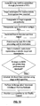
- Fig. 10 shows a flow diagram of the steps in accordance with this embodiment of the present invention.
- the first step is to arrange a plurality of antenna elements (RUs), preferably within the confines of an airport. At least one of the antenna elements must be both transmit and receive capable (transmitter/receiver RU), whereas the remaining elements can be receiver-only RUs.
- RUs antenna elements
- the transmitter/receiver RU transmits an interrogation signal to the target and records the time of transmission.
- the target's transponder transmits a reply signal with known data (e.g., Mode S address, aircraft identification, altitude, etc.).
- the RU that transmitted the interrogation signal and at least two additional RUs not subject to line of sight or multipath issues receive the reply.
- the received data is decoded and time-tagged with the TOA information.
- the received data, TOA, and recorded transmission time of the interrogation signal are then sent to processing unit 3.
- the processing unit 3 clusters the target data such that a cluster contains information from a single transmission by the same target received by multiple RUs.
- the inputs to the Two-Dimensional Closed Form Range Aided Algorithm include:
- the output of the Two-Dimensional Closed Form Range Aided Algorithm is an estimate of the target's position
- the first step is to order the RU coordinates and their associated TOAs in the algorithm such that RU 1 is the RU from which the range is measured.
- A - 2 ⁇ x 2 - 2 ⁇ y 2 - 2 ⁇ x 3 - 2 ⁇ y 3 - 1 Note that the elements of the above matrix are later referred to by A ij where (i,j) are the row and column respectively.
- b 1 d 1 2 - R 2 2 - 2 ⁇ d 1 ⁇ R + 2 ⁇ zz 2
- b 2 d 2 2 - R 3 2 - 2 ⁇ d 2 ⁇ R + 2 ⁇ zz 3
- x ⁇ p 1 A 11 ⁇ b 1 - 2 ⁇ d 1 ⁇ R + A 12 ⁇ b 2 - 2 ⁇ d 2 ⁇ R
- y ⁇ p 1 A 21 ⁇ b 1 - 2 ⁇ d 1 ⁇ R + A 22 ⁇ b 2 - 2 ⁇ d 2 ⁇ R
- the output of the Two-Dimensional Closed Form Range Aided Algorithm is the position estimate (x i , y i , z i ).
- the input to the Two-Dimensional MLE Range Aided Algorithm consist of:
- the output from the Two-Dimensional MLE Range Aided Algorithm is a precise location of the target in x, y, z form.
- the first step is to order the RUs in the algorithm such that RU 1 is the RU from which the range was measured.
- the Two-Dimensional MLE Range Aided Algorithm is an iterative solution that requires an initial guess (x i , y i , z i position estimate) to start and continuously approximates a new position estimate. Expected TOAs are calculated for each new position estimate and the cost function of the Two-Dimensional MLE Range Aided Algorithm measures the error between the calculated TOAs and the measured TOAs.
- the cost function is defined to be the norm of the difference between the expected TOAs derived from the current position estimate (x i , y i , z i ) and the measured TOAs. Again, the range is included to improve the accuracy of the final calculated position of the target.
- the Two-Dimensional MLE Range Aided Algorithm is iterated until subsequent estimates are sufficiently close together that the cost function returns a value equal to or less than a predetermined value.
- a number of RUs are placed in known positions within the airport confines as shown in Fig. 1 .
- any combination of at least four receivers and one transmitter is required to provide three-dimensional localization of targets in and around the airport.
- the RUs can receive only, transmit only, or both transmit and receive and additional RUs may be required to overcome Line of Sight (LOS) obstructions and multipath issues.
- LOS Line of Sight
- each RU includes a TOA device 2 to provide an accurate time stamp of the Time of Arrival (TOA) of each transponder signal received from a target.
- the RUs 1 are connected by a communication means to a processing unit 3.
- the signal flow between a transmitter/receiver RU 4, a target 5 and three receiver RUs 6 is shown in Fig. 11 .
- the interrogation signal 7 is sent from the transmitter/receiver RU 4 to solicit a reply 8 from the target's 5 transponder.
- Transmitter/receiver RU 4 records the time of the transmission of the interrogation signal 7 for later use in calculating the target's range.
- the transponder inside the target replies automatically within a known amount of time subject to a tolerance as previously described.
- the reply signal is received at all of the RUs 4, 6, 6, 6 where the data is decoded and time tagged with its Time of Arrival (TOA) from the TOA device 2.
- TOA Time of Arrival
- Each RU then sends the data with its time stamp over a data link to the processing unit 3 for further evaluation.
- the transmitter/receiver RU 4 provides the time of transmission of the interrogation signal 7 over the data link to the processing unit 3.
- the processing unit clusters the decoded data with each cluster containing a specific transmission received at each RU from a specific target. Clustering is typically performed through target number identification, Mode S address, or Mode 3/A Code; however other proven methods are also available. As will be explained below in more detail, the processing unit then performs calculations utilizing the target data and recorded transmission time of the interrogation signal provided by the RUs to determine the precise location of the target.
- the next step is to determine whether the target's range can be used in the position estimate calculation.
- a range threshold check is performed due to variations in the processing times of the target's transponder as previously described.
- the coordinates of the RUs that received the signals, the measured TOAs, the calculated range and the RU from which the range was measured are input to the Three-Dimensional Closed Form Range Aided Algorithm of the present invention.
- the Three-Dimensional Closed Form Range Aided Algorithm provides an estimate of the target's position in a Cartesian coordinate system as x, y, z data and is similar to the Two-Dimensional Closed Form Range Aided Algorithm as will be seen in the following description.
- the algorithm first orders the RU coordinates and their associated TOAs so as to set RU 1 in the algorithm as the RU from which the range is measured. This is significant in that the TOAs from the remaining RUs are then subtracted from the TOA of RU 1 for calculating the Time Differential of Arrivals (TDOAs) used to calculate the position estimate.
- TDOAs Time Differential of Arrivals
- the coordinates of the RUs are then translated such that RU 1 is at the origin of the Cartesian coordinate system and the distance from the remaining RUs to the new origin (RU 1 ) is calculated.
- a matrix of RU position values is developed and a new vector that combines the TDOAs and the RU ranges is calculated from which the position estimate is directly available.
- the position estimate at this point is in a Cartesian coordinate system with RU 1 at the origin so it is necessary to translate back to the original Cartesian coordinate system with the system center at the origin for the final position estimate of the target in x, y, z form
- the position estimate from the Three-Dimensional Closed Form Range Aided Algorithm is further refined through the Three-Dimensional MLE (Maximum Likelihood Position Estimate) Range Aided Algorithm.
- the Three-Dimensional MLE Range Aided Algorithm requires, as inputs, the initial position estimate of the target, coordinates of the RUs, associated measured TOAs, range measurement and RU from which the range was measured (RU 1 ).
- the Three-Dimensional MLE Range Aided Algorithm is an iterative solution that continuously approximates a new position estimate and calculates expected TOAs corresponding to the new position estimates.
- the Three-Dimensional MLE Range Aided Algorithm further includes a cost function that measures the error between calculated TOAs and the measured TOAs.
- the cost function is defined to be the norm between expected TOAs corresponding to the position estimate and the measured TOAs with the range measurement included as will be more specifically described later.
- Other search function evaluation methods such as the Newton-Raphson Method and Simplex Downhill Method can be used with results similar in accuracy.
- Fig. 12 shows a flow diagram of the steps in accordance with this embodiment of the present invention.
- the first step is to arrange a minimum of four antenna elements (RUs), preferably within the confines of an airport. At least one of the antenna elements must be both transmit and receive capable (transmitter/receiver RU), whereas the remaining elements can be receiver-only RUs.
- RUs antenna elements
- the transmitter/receiver RU transmits an interrogation signal to the target and records the time of transmission.
- the target's transponder transmits a reply signal with known data (e.g., Mode S address, aircraft identification, altitude, etc.).
- the RU that transmitted the interrogation signal and at least three additional RUs not subject to line of sight or multipath issues receive the reply.
- the received data is decoded and time-tagged with the TOA information.
- the received data, TOA, and recorded transmission time of the interrogation signal are then sent to processing unit 3.
- the processing unit 3 clusters the target data such that a cluster contains information from a single transmission by the same target received by multiple RUs.
- the inputs to the Three-Dimensional Closed Form Range Aided Algorithm include: .
- the output from the Three-Dimensional Closed Form Range Aided Algorithm is an estimate of the target's position.
- the first step is to order the RU coordinates and their associated TOAs in the algorithm such that RU 1 is the RU from which the range is measured.
- TDOAs Time Difference of Arrivals
- R 2 x 2 2 + y 2 2 + z 2 2
- R 3 x 3 2 + y 3 2 + z 3 2
- R 4 x 4 2 + y 4 2 + z 4 2
- A - 2 ⁇ x 2 - 2 ⁇ y 2 - 2 ⁇ z 2 - 2 ⁇ x 3 - 2 ⁇ y 3 - 2 ⁇ z 3 - 2 ⁇ x 4 - 2 ⁇ y 4 - 2 ⁇ z 4 - 1
- a ij the elements of the above matrix are later referred to by A ij where (i,j) are the row and column respectively.
- x ⁇ p 1 A 11 ⁇ b 1 - 2 ⁇ d 1 ⁇ R + A 12 ⁇ b 2 - 2 ⁇ d 2 ⁇ R + A 13 ⁇ b 3 - 2 ⁇ d 3 ⁇ R
- the output of the Three-Dimensional Closed Form Range Aided Algorithm is the position estimate (x i , y i , z i ) of the target.
- the inputs to the Three-Dimensional MLE Range Aided Algorithm consist of:
- the output from the Three-Dimensional MLE Range Aided Algorithm is a precise location of the target in x, y, z form.
- the first step is to order the RUs in the algorithm such that RU 1 is the RU from which the range is measured.
- the Three-Dimensional MLE Range Aided Algorithm is an iterative solution that requires an initial guess (x i , y i , z i position estimate) to start and continuously approximates a new position estimate. Expected TOAs are calculated for each new position estimate and the cost function of the Three-Dimensional MLE Range Aided Algorithm measures the error between the calculated TOAs and the measured TOAs.
- the cost function is defined to be the norm of the difference between the expected TOAs derived from the current position estimate (x i , y i , z i ) and the measured TOAs.
- the range is included to improve the accuracy of the final calculated position of the target.
- this invention can be particularly useful to airports that do not have, and cannot afford an expensive radar system. Additionally, this invention can be used to greatly extend the effective range of current air traffic surveillance systems without the requirement of additional transmitting antennas or RUs placed outside the system boundaries.
Landscapes
- Engineering & Computer Science (AREA)
- Radar, Positioning & Navigation (AREA)
- Remote Sensing (AREA)
- Physics & Mathematics (AREA)
- General Physics & Mathematics (AREA)
- Computer Networks & Wireless Communication (AREA)
- Radar Systems Or Details Thereof (AREA)
- Position Fixing By Use Of Radio Waves (AREA)
Abstract
Description
- The invention relates to ground-based or airborne air traffic surveillance systems, particularly to direction finding and target localization using a TDOA (Time Differential of Arrival) distributed antenna.
- In the current art a number of systems and methodologies exist for the localization of ground vehicles and aircraft (e.g., targets) in and around air traffic surveillance systems which can include airports, terminal areas and en route systems.
- Many large airports utilize approach radar systems to locate and track targets outside the airport. These radar systems obtain good azimuth accuracy by using the narrow beam available from the large aperture antenna, whereas the range is calculated from the round trip delay of the signal from the radar to the target and back. Typically these approach radar systems require large rotating antennas making them expensive. In addition, these radar systems characteristically have an update rate of approximately 4.5 seconds, and consequently the response speed of the associated analysis equipment is limited by the update rate of the radar.
- A second method for target localization is multilateration. Multilateration systems typically are made up of an arrangement of beacon transmitters and receivers. Multilateration is a Time Differential of Arrival (TDOA) technique that uses information from aircraft transponder transmissions to determine the precise location of a target. The algorithm for multilateration typically starts by estimating, using TDOA information, the approximate location of a target in either a two-dimensional or three-dimensional coordinate system. An optimization process is then performed around the approximate location of the target to provide a more accurate location of the target.
- Multilateration systems can be used to locate and track targets on the ground at the airport for runway incursion and can also be used for locating and tracking approaching aircraft within relative close proximity to an airport and by en route air traffic surveillance systems. However, if it is required to provide large area coverage around the multilateration system, the ratio of the antenna baseline (distance between the receivers) to the range of the target becomes such that the Geometric Dilution of Precision (GDOP) becomes quite large. It therefore becomes more difficult to locate the target within the "ellipse of uncertainty" and the effectiveness of the multilateration system is significantly degraded as the distance from the system to the target increases.
- One method to overcome this problem with the current multilateration technique is to install external antenna elements outside the boundaries of the multilateration system to increase the size of the antenna baseline. This, however, creates difficulties with regard to purchasing additional real estate, providing security outside of the,system, maintenance of the external antenna elements, communication between the external antenna elements and the system, and other logistical issues.
- While many air traffic surveillance systems are using one, or a combination of the above-detailed methodologies, some airports currently have no local, reliable methodologies for locating approaching aircraft, or vehicles on the ground for runway incursion. Some of these airports have adopted the practice of acquiring radar data from larger, better-equipped airports in their vicinity to provide information on the air traffic in their area. While this process can be beneficial to airports that would otherwise not have this information available, it is possible for targets of interest to the dependent airport to be obscured from the providing airport's radar by line of sight obstructions.
- A need exists, therefore, for a reliable, relatively low cost solution to provide an air traffic surveillance system with the capability to locate targets en route, locate targets approaching the airport, locate targets on the ground as a component of a runway incursion system, improve the handover between approach systems and runway incursion systems, and to extend the range and accuracy of target localization utilizing existing air traffic surveillance systems without the need to install antenna elements outside the system boundaries.
- In contradiction to that methods and apparatus to position a mobile receiver using downlink signals are known from
US 6,208,297 B1 . - It is an object of the present invention to overcome the problems of the prior art by providing a system and methods for high direction and location finding accuracy utilizing existing air traffic surveillance systems, and without requiring large individual antenna aperture, mechanical antenna rotation, or additional receivers outside the system boundaries.
- The invention relates to a system which can be used to perform several methods of target localization. The system includes at least one transmitter for transmitting a signal to a target, and at least one receiver for receiving a return signal from the target to calculate the RTD (Round Trip Delay) of the signal. The system further includes at least three receivers for receiving a return signal from the target and a mechanism for determining the Time of Arrival (TOA) of the signals at each receiver. The system also includes a central processor for calculating TDOAs (Time Difference of Arrivals) and performing the localisation calculations in accordance with the methods of the invention as will be described in more detail below.
- The methods of the invention calculate at least an estimate of a target's position using TDOA and RTD data obtained from target transponder signals. The TDOAs are calculated by measuring the TOA of a transponder signal from the target when the signal is received at a plurality of receiver units. The receiver utilized to calculate the RTD can also function as one of the three receivers used to calculate the TDOA. Each TOA is subtracted from the TOA of a designated receiver to produce the TDOAs. Transmitting an interrogation signal from a transmitter to a target and measuring the delay time between the time of transmission of the interrogation signal and the time of arrival of the reply signal from the target at a receiver determines the RTD. The RTD data can then be used to calculate the target's precise range. By using the TDOA data in conjunction with the range provided from the RTD data, the range GDOP issues associated with the prior art multilateration technique are overcome and the range accuracies, and therefore the overall position accuracies, improve dramatically.
- The method of one embodiment of the present invention calculates azimuth of a target based on TDOA data of transponder replies received by at least three antenna elements (receiving units, "RUs"), which effectively create an antenna array. When the distance of the target is much greater than the baseline, it is possible to use a simple linear approximation that computes the azimuth and elevation. If range only, or range and height are available as well, it is possible to considerably improve the measurement accuracy by performing an azimuth search at the given range and height that best matches the measured TDOA.
- The signals received at the ground-based RUs are typically generated by transponders onboard the target aircraft. When the data is received as a function of a response to an interrogation from a ground-based transmitter, the round trip delay of the messages is calculated and stored for use in range calculations.
- The received data is processed by the RUs, time stamped with Time of Arrival information (TOA) to be used in Time Differential of Arrival (TDOA) calculations and sent to the processing unit for further evaluation. At the processing unit the data is sorted into distinct clusters, each representing a specific transmission from a distinct target, and evaluated to give an initial approximation of the azimuth. A search function is then performed around the initial azimuth to compensate for non-linear errors. The search function is performed by creating an arc about the initial azimuth at a range calculated from the RTD data and the height calculated from the altitude data provided in the transponder response. The size of the arc is set to approximately twice the size of the antenna baseline. A predetermined number of points along the arc are selected where each point has the same associated RTD as calculated from the transponder reply signal. Calculating the expected TDOA for each selected point on the arc and comparing that expected TDOA to the measured TDOA yields an error. The azimuth associated with the expected TDOA having the minimum error is selected as a more precise azimuth of the target. A more precise plane position of the target is then calculated using the more precise azimuth and the RTD data.
- The search function is reiterated a specific number of times using a smaller arc each time, thereby improving the accuracy of the position estimate. If range is unavailable, then this method will compute approximate azimuth and elevation only. The azimuth that yields the smallest error from the search function is selected. Finally, the x and y positions are calculated and the height (z) is included if calculated from the altitude data.
- The method according to another embodiment of the invention calculates a two-dimensional position estimate of a target utilizing TOA and RTD information when a transponder signal is received by at least three receivers as previously discussed. In accordance with this embodiment of the present invention, the height of the target is known and used as the z coordinate to improve the position estimate of the target. The height can be calculated from the altitude data provided by the target in the transponder signal or alternately, the height can be known by a determination that the target is on the ground. In accordance with this embodiment, the measured TOAs, target height and calculated range are provided in conjunction with the coordinates of the RUs to a closed form range aided algorithm. This method of the present invention will calculate a two-dimensional (x, y) position estimate of the target and the known height will be used as the z coordinate to provide a three-dimensional position estimate.
- The position estimate, target height and the calculated range are then provided to a search function to further improve the position estimate. The search function approximates a new position estimate of the target and calculates TOAs that correspond to the new position estimate. The search function further includes a cost function which measures the error between the TOAs of the original (current) position estimate and the TOAs of the new position estimate. The position estimate that results in the smallest error is selected as the new current position estimate. The search function is reiterated, each time using the position estimate with the smallest error as the new current position estimate until the error is less than or equal to a predetermined minimum.
- The method of yet another embodiment of the present invention calculates a three-dimensional position estimate of a target utilizing the TOA and RTD information when a transponder signal is received by at least four receivers as previously discussed. In accordance with this embodiment of the present invention, the height of the target is not known. Therefore, only the measured TOAs and calculated range in conjunction with the coordinates of the RUs are provided to a closed form range aided algorithm. This method of the present invention will calculate a three-dimensional (x, y, z) position estimate of the target directly from the TOA and RTD data.
- The three-dimensional position estimate and the calculated range are then provided to a search function to further improve the position estimate. The search function approximates a new position estimate of the target and calculates TOAs that correspond to the new position estimate. The search function further includes a cost function which measures the error between the TOAs of the original (current) position estimate and the TOAs of the new position estimate. The position estimate that results in the smallest error is selected as the new current position estimate. The search function is reiterated, each time using the position estimate with the smallest error as the new current position estimate until the error is less than or equal to a predetermined minimum.
- For a better understanding of the nature and objects of the invention, reference should be made to the following detailed description of preferred modes of practicing the invention, read in connection with the accompanying drawings, in which:
-
Fig. 1 is a representation of a typical receiving unit (RU) arrangement in an airport; -
Fig. 2 is a representation of the typical connections between RUs, associated TOA devices and a processing unit; -
Fig. 3 shows the signal flow that provides TOA data and range calculation using a round trip delay method in accordance with two embodiments of the present invention; -
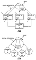
Fig. 4 shows the signal flow in accordance with another embodiment of the present invention when different RUs are utilized for the transmit and receive functions to determine range; -
Fig. 5 is a representation of a search function utilized to determine the precise location of the target in accordance with a preferred embodiment of the present invention; -
Fig. 6 is a graphical representation of the results of the search function; -
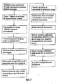
Fig. 7 is a flow diagram of a process used to determine target position in accordance with one embodiment of the present invention; -
Fig. 8 is a two dimensional representation of a model used to explain an algorithm in accordance with one embodiment of the present invention; -
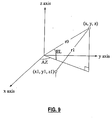
Fig. 9 is a three dimensional representation of a model used to further develop the algorithm in accordance with one embodiment of the present invention; -
Fig. 10 is a flow diagram of another process used to determine target position in accordance with another embodiment of the present invention; -
Fig. 11 shows the signal flow that provides TOA data and range calculation using a round trip delay method in accordance with another embodiment of the present invention; and -
Fig. 12 is a flow diagram of another process used to determine target position in accordance with another embodiment of the present invention. - One embodiment of the present invention will now be described with reference to
Figs. 1-9 . A number of antenna elements 1 (hereafter referred to as "receiving units" (RUs)) are placed in known positions within the airport confines to create an antenna array as depicted inFig. 1 . A typical RU is sold by Sensis Corporation (Model No. 100-008121-G001). The distance and placement of the RUs is referred to as the antenna array baseline or baseline. In this embodiment, any combination of at least one transmitter and three receivers is required to provide three-dimensional localization of targets in and around the airport. The RUs can receive only, transmit only, or both transmit and receive. More RUs may be required dependent upon the geography and building layout in and around the airport in order to overcome Line of Sight (LOS) obstructions and multipath issues. In accordance with the present invention, all of the RUs can be positioned within the confines of the airport, thus insuring easy access for maintenance and security, and simplifying communications. In a preferred embodiment, the transmit antenna elements are capable of transmitting a 1030 MHz phase modulated uplink signal and the receive antenna elements are capable of receiving a 1090 MHz amplitude modulated down link signal, however, any signals in space could be used. -
Fig. 2 shows that each RU 1 includes aTOA device 2 that accurately measures the Time of Arrival (TOA) of each transponder signal received from a target. The RUs 1 are connected by some communication means, such as a local area network (LAN) for example, to aprocessing unit 3, which performs the localization calculations. Other types of communication means such as Rf links or telephony can also be used and the invention is not thereby limited. - In one sense, the layout of RUs shown in
Fig. 1 and the devices shown inFig. 2 are the same as those employed to locate targets using the traditional multilateration technique. As explained earlier, however, the GDOP associated with the range of the target becomes quite large as the ratio of the antenna baseline (distance between the receivers) to the range of the target decreases. It therefore becomes more difficult to locate the target within the "ellipse of uncertainty" and the effectiveness of the multilateration system is significantly degraded as the distance from the multilateration system to the target increases. In accordance with the present invention, however, range aided position algorithms are used to extend the effective range of the RU infrastructure as shown inFigs. 1 and 2 to precisely locate the target at significantly increased distances from the system, as will be explained below in more detail. -
Fig. 3 shows the signal flow between a transmitter/receiver RU 4, atarget 5 and two receiver RUs 6. Aninterrogation signal 7 is sent from the transmitter/receiver RU 4 to solicit areply 8 from the target's 5 transponder. Transmitter/receiver RU 4 records the time of the transmission of theinterrogation signal 7 for later use in calculating the target's range. The transponder inside the target replies automatically within a known amount of time (internal delay) subject to a tolerance as will be described later. The reply signal is received at all of the RUs 4, 6, 6 where the data is decoded and time tagged with its Time of Arrival (TOA) from theTOA device 2. Multiple methods can be used to determine TOA including, but not limited to, Global Positioning System (GPS) data, localized clocks and internal counters. Transponder reply signals contain a wealth of information for use by air traffic control personnel. This information can include, but is not limited to, Mode S address, flight identification number and altitude data, depending on the type of reply solicited. Each RU then sends the data with its time stamp over a data link to theprocessing unit 3 for further evaluation. Additionally, the transmitter/receiver RU 4 provides the time of transmission of theinterrogation signal 7 over the data link to theprocessing unit 3. - The processing unit clusters the decoded data with each cluster containing a specific transmission received at each RU from a specific target. Clustering is typically performed through target number identification, Mode S address, or
Mode 3/A Code; however other proven methods are also available. As will be explained below in more detail, the processing unit then performs calculations utilizing the target data and recorded transmission time of the interrogation signal provided by the RUs to determine the precise location of the target. - The time that the interrogation was sent from the transmitter/receiver RU 4 to the target is known, as is the internal delay of the target's transponder, and the time of arrival of the target's return signal at transmitter/receiver RU 4. This data is used to calculate the round trip delay to determine the precise range of the target. In a preferred embodiment, the same antenna is used to both transmit and receive the signal used for the range calculation. In this manner, the precise range of the target aircraft can be calculated based only on the round trip delay data by the following formula:

- R =
- Range
- RTD =
- Round trip delay (elapsed time from transmission of interrogation signal to reception of reply signal)
- delay =
- internal delay of target's transponder
- c =
- speed of light
- In another embodiment, however, as shown in
Fig. 4 , atransmitter RU 40 could be used in combination with three receiver RUs 60 (i.e., transmission and reception of the signal are not through the same antenna.) If this embodiment is adopted, precise range of the target will be known only after the azimuth of the target is calculated. That is, since the round trip delay is measured from the antenna oftransmitter RU 40 to the antenna of one of the receivingRUs 60, the precise range of the target will not be known until the azimuth of the target is calculated as well. In both scenarios shown inFigs. 3 and 4 , however, since the range is calculated from round trip delay data, the GDOP issues associated with the prior art multilateration techniques are overcome and the range accuracies improve dramatically (e.g., for ranges outside of the airport in excess of 20 miles) without any change in the RU infrastructure. - Using round trip delay to calculate target range either alone (
Fig. 3 ) or in combination with the azimuth of the target (Fig. 4 ) is only one step of the process. The next step requires using the clustered TDOA data for each target. Specifically, the TDOAs between the transponder replies belonging to the same cluster are calculated utilizing the TOA from one RU as a reference, which effectively eliminates time biases. This set of TDOAs will be referred to as measured TDOAs. A first approximation of the azimuth is then calculated by evaluating the measured TDOAs in conjunction with the known positions of the RUs using a linear approximation. - The data is further refined through an azimuth search around the first approximation of the azimuth that best matches the measured TDOA at the measured range and height. The height is calculated from the altitude data included in the transponder reply as is well known in the art. Referring to
Fig. 5 , anarc 9 is created about the first approximation of the azimuth at the range and height determined from the altitude data from the transponder reply (return signal). In the preferred embodiment of the invention (Fig. 3 ), the created arc represents a portion of a circle due to the fact that the same antenna was utilized to transmit the interrogation and receive the transponder reply signal for use in the range calculation (based on round trip delay), which greatly simplifies the search. If different antennas are utilized to transmit the interrogation and receive the reply signal (Fig. 4 ), then the arc will represent a portion of an ellipse. Although this will somewhat complicate the search algorithm, the search can still be performed with little or no degradation in accuracy. - By way of example only, the arc is selected to be approximately twice the size of the antenna baseline (distance between the two RUs which are farthest apart), and ten individual points (azimuths) 10, each having the same round trip delay (RTD) as calculated from the return signal, are taken along the
arc 9. For each azimuth point in the search, the TDOA is calculated from a known model, described below. This set of TDOAs will be referred to as expected TDOAs. The minimum error between the expected TDOAs and the measured TDOAs is then calculated. As depicted inFig. 6 , the azimuth associated with the expected TDOAs that produces theminimum error 11 is selected. Preferably, the arc is then reduced to a tenth of its original size about the new azimuth and a second set of ten new points is taken on the smaller arc. This process is reiterated a predetermined number of times based upon system parameters including, by way of example, antenna baseline size and the range accuracies of the antennas. The number of iterations is particular to a given system and is determined during system deployment. - Since the precise range is being determined from the round trip delay data and the height is being calculated from the altitude data provided by the transponder response, the search function is performed in one dimension, thereby significantly reducing the complexity as compared to a multilateration type search. Other search function evaluations methods such as Steepest Rate of Descent techniques can be used with results similar in accuracy.
- The x, y and z coordinates are then determined from the finally calculated azimuth and range, and the height as calculated from the altitude data in the transponder return signal to provide precise three-dimensional localization of the target. This data is then made available to the air traffic control operators for display.
-
Fig. 7 shows a flow diagram of the steps in accordance with this embodiment of the present invention. The first step is to arrange a plurality of antenna elements, preferably within the confines of an airport. In a preferred embodiment, at least one of the antenna elements must both transmit and receive the signal (transmitter/receiver RU), whereas the remaining elements can be receiver-only RUs. - The transmitter/receiver RU transmits a signal to the target, and the target transmits a reply signal with known data (e.g., aircraft identification, altitude, etc.). The reply signal is received by either the antenna of the transmitter/receiver RU that transmitted the interrogation signal or another RU antenna. The reply signal is also received by at least two additional RUs. The received data is decoded and time-tagged with the TOA information, and then sent to
processing unit 3 where it is clustered and utilized to calculate target range and initial (approximate) azimuth. - In accordance with the preferred embodiment shown in
Fig. 3 , the reply signal is received through the same antenna that transmitted the interrogation signal such that the round trip delay can be used to provide the precise range of the target. Measured TDOA is then calculated and evaluated to determine the initial azimuth of the target, and thereafter a search function is performed around the initial azimuth to compensate for non-linear errors. The search function is repeated a predetermined number of times based on system parameters. The precise three-dimensional location of the target is then determined (again, the height of the target is determined by the altitude data in the reply signal from the target). - In accordance with this embodiment of the present invention, a specific algorithm is used to determine the initial (approximate) azimuth of the target. Another specific algorithm is used to perform the search function around the initial azimuth and provide a more accurate azimuth for the target. The manner in which those algorithms were developed will now be described.
- A geometric representation of reply signal reception by two RUs is shown in
Fig. 8 . The exact expression for the measured TDOA is derived utilizing the cosine theorem as follows:


- Using the coordinate system depicted in
Fig. 9 , this approximation is extended to the three dimensional case as follows:
- r1
- True range from the target to the RU.
- (x, y, z)
- Coordinates of the target
- (x1,y1,z1)
- Coordinates of the receiving RU.
- As one skilled in the art can appreciate, evaluating only the linear portion of the Taylor Series will induce non-linear errors but will still give an acceptable first approximation of the azimuth. The impact of these errors will be mitigated through the search function described in detail later.
- The TOA to each receiver (RU) is:

- Using multiple receivers the above equation can be generalized to a matrix form:


- (ru_mat_full contains the locations of all receivers),
- (u_mat is the direction vector in sine space).
- The TOA bias is common to all receivers. Therefore, by taking one RU as a reference and subtracting its TOA from all other RUs' TOA, the TOA bias can be eliminated and the measured TDOAs are determined. The first RU to supply the data is typically chosen as the reference RU, however any RU can be used. Therefore, the relevant matrix expression is:


- Equation (11) can be written in a more compact form as:


- The direction vector in sine space is a multiplication of a fixed matrix that depends on the RU locations and the measured TDOA vector and gives the initial azimuth.
- It should be noted that equation (11) ignores the z coordinates of the receivers. This is done in order to maintain the linearity of the equation. The contribution of z to the range from receiver to target is negligible compared to the contribution of x and y. It should also be noted that subsequent steps of the algorithm compensate for z.
- Performing a one-dimensional optimization search in azimuth compensates for the non-linear errors. The search is performed by creating an arc about the first approximation of the azimuth at the range and height calculated from the altitude data in the transponder reply signal as previously defined. A predetermined number of points on the arc are selected for evaluation, each selected point having the same round trip delay (RTD) as calculated from the transponder reply signal. It is assumed that the range and the height are constant, as they are given by the transponder reply signal. In the event that height is not available, it is set to zero, and the algorithm will find the coordinate projection on the x-y plane.
- To perform the search, the expected TDOA for each azimuth is calculated from the known model depicted in
Fig. 9 as follows: - 1. The x, y, z of the selected point on the arc is calculated using simple trigonometric equations assuming a circle with a constant RTD for a case of transmitter/receiver using the same antenna, or an ellipse with a constant RTD if the transmitter and receiver are using different antennas.
- 2. The distance to each RU is calculated using the x, y, z previously calculated on the arc and the known x1, y1, z1 of the selected RU. This step is repeated for each RU.
- 3. The expected TOA at each RU is calculated by dividing the distance by the speed of light (c).
- 4. The TOA of the reference RU (the reference RU is the same one chosen to calculate the measured TDOA) is subtracted from the TOAs of each individual RU.
- 5. The result is the expected TDOA vector to be used in evaluating the search function.
- The following cost function is then evaluated for the azimuth search:

- tdoa_measj
- Measured TDOA in RU # j
- tdoa_expected(azij,R,H)
- Expected TDOA in the ith azimuth for RU #j
- The range R and height H are held constant, equal to information derived from the transponder reply signal. The function is calculated over i points (e.g., 10), where each point has the same round trip delay (RTD) as calculated from the transponder reply signal as previously mentioned, and the azimuth associated with the expected TDOA that produces the lowest error is selected. In the event that height is not available, it is set to zero, and the algorithm will find the coordinate projection on the x-y plane. The search function is repeated by creating a new smaller arc (e.g., one-tenth the size of the original arc) about the new azimuth (i.e., that produced the lowest error). The cost function is then repeated over a second i points (e.g., 10). Again the azimuth associated with the expected TDOA that produces the lowest error is selected. This search function process is repeated a predetermined number of times, as previously discussed, with the final azimuth producing the lowest TDOA error from the cost function.
- Dividing the height by the range calculated from the RTD data and taking the inverse-sine of the result gives the elevation of the target. Once the elevation and optimal azimuth have been determined, the three-dimensional coordinates are calculated as follows:

- R =
- Measured range
- az_c =
- Optimal azimuth as calculated by the search process
- Height =
- Calculated from altitude data in transponder reply.
- If height cannot be calculated from the transponder reply, it is set to zero and only the x and y coordinates are calculated.
- If a transponder signal is received that is not in response to an interrogation from an RU, then range cannot be determined from the RTD information. In some instances of this scenario, the height may be unavailable as well, as the signal from the target does not include altitude data. If height and range are not available, then this method will compute approximate azimuth and elevation directly from equation (13). The accuracy will depend on the ratio between the antenna baseline and range, and will improve as the range increases. Another approximation is the z dimension of the antenna array. The approximation will improve if the z dimension of the antenna array decreases relative to the baseline.
- An identical method for radar target localization can be employed if one RU is used as a radar transmitter and multiple RUs as radar receivers. As previously described, range can be calculated from the round trip delay and azimuth from the TDOA information.
- Another embodiment of the present invention will now be described with reference to
Figs. 1-3 and10 . As in the first embodiment, a number of RUs are placed in known positions within the airport confines as shown inFig. 1 and any combination of at least three receivers and one transmitter is required to provide three-dimensional localization of targets in and around the airport where the RUs can receive only, transmit only, or both transmit and receive. - As in the first embodiment each RU includes a
TOA device 2 to provide an accurate time stamp of the Time of Arrival (TOA) of each transponder signal received from a target. The RUs 1 are connected by a communication means to aprocessing unit 3. The signal flow between a transmitter/receiver RU 4, atarget 5 and two receiver RUs 6 is as shown inFig. 3 . Theinterrogation signal 7 is sent from the transmitter/receiver RU 4 to solicit areply 8 from the target's 5 transponder. Transmitter/receiver RU 4 records the time of the transmission of theinterrogation signal 7 for later use in calculating the target's range. The transponder inside the target replies automatically within a known amount of time subject to a tolerance as will be described later. The reply signal is received at all of the RUs 4, 6, 6 where the data is decoded and time tagged with its Time of Arrival (TOA) from theTOA device 2. Each RU then sends the data with its time stamp over a data link to theprocessing unit 3 for further evaluation. Additionally, the transmitter/receiver RU 4 provides the time of transmission of theinterrogation signal 7 over the data link to theprocessing unit 3. - The processing unit clusters the decoded data with each cluster containing a specific transmission received at each RU from a specific target. Clustering is typically performed through target number identification, Mode S address, or
Mode 3/A Code; however other proven methods are also available. As will be explained below in more detail, the processing unit then performs calculations utilizing the target data and recorded transmission time of the interrogation signal provided by the RUs to determine the precise location of the target. - When the target's height is known, a two-dimensional (x, y) position estimate of the target can be calculated and the height used as the z coordinate to provide a three-dimensional estimate. The height can be calculated from the altitude data provided by the target in the transponder reply signal or alternately, the height can be known by a determination that the target is on the ground. In any case, the final output of the range aided algorithms of this embodiment of the present invention is a precise x, y, z position of the target as the provided height is used to supply the z coordinate.
- The next step is to determine whether the target's range can be used in the position estimate calculation. The range is calculated by the range formula previously disclosed. A range threshold check is performed to determine if the calculated range can be used. The range threshold check is required due to the variations in the signal processing time of the
interrogation signal 7 by the target's transponder. Processing times in the transponders that produce the reply signal are subject to a tolerance of as much as ±0.5µsec from the nominal value, which can result in errors in range of approximately 250 feet. These errors become negligible in distances further from the airport, however, for closer targets these errors become prohibitive due to the ratio between the error and the target's range. Therefore, when the target is within a predetermined range of the airport it is desirable to calculate the target's position without using the range calculated from the RTD data. The range threshold is determined at system deployment and provided to theprocessing unit 3. - To determine the target's two-dimensional position using the range calculated from the RTD data, the coordinates of the RUs that received the signals, the measured TOAs, the provided height, the calculated range and the RU from which the range was measured are input to the Two-Dimensional Closed Form Range Aided Algorithm of the present invention. The Two-Dimensional Closed Form Range Aided Algorithm provides an estimate of the target's position in a Cartesian coordinate system as x, y, z data using the provided height as the z coordinate.
- The algorithm first orders the RU coordinates and their associated TOAs so as to set RU1 in the algorithm as the RU from which the range is measured. This is significant in that the TOAs from the remaining RUs are then subtracted from the TOA of RU1 for calculating the Time Differential of Arrivals (TDOAs) used to calculate the position estimate. The coordinates of the RUs are then translated such that RU1 is at the origin of the Cartesian coordinate system and the distance from the remaining RUs to the new origin (RU1) is calculated. A matrix of RU position values is developed and a new vector that combines the TDOAs and the RU ranges is calculated from which the position estimate is directly available. The position estimate at this point is in a Cartesian coordinate system with RU1 at the origin so it is necessary to translate back to the original Cartesian coordinate system with the system center at the origin for the final position estimate of the target in x, y, z form with the provided height used as the z coordinate.
- The position estimate from the Two-Dimensional Closed Form Range Aided Algorithm is further refined through the Two-Dimensional MLE (Maximum Likelihood Position Estimate) Range Aided Algorithm. The Two-Dimensional MLE Range Aided Algorithm requires, as inputs, the initial position estimate of the target (with the height used as the z coordinate), coordinates of the RUs, associated measured TOAs, range measurement and RU from which the range was measured (RU1). The Two-Dimensional MLE Range Aided Algorithm is an iterative solution that continuously approximates a new position estimate and calculates expected TOAs corresponding to the new position estimates. The Two-Dimensional MLE Range Aided Algorithm further includes a cost function that measures the error between calculated TOAs and the measured TOAs. For the position estimate calculation, the cost function is defined to be the norm between expected TOAs corresponding to the position estimate and the measured TOAs with the range measurement included as will be more specifically described later. Other search function evaluation methods such as the Newton-Raphson Method and Simplex Downhill Method can be used with results similar in accuracy.
-
Fig. 10 shows a flow diagram of the steps in accordance with this embodiment of the present invention. The first step is to arrange a plurality of antenna elements (RUs), preferably within the confines of an airport. At least one of the antenna elements must be both transmit and receive capable (transmitter/receiver RU), whereas the remaining elements can be receiver-only RUs. - The transmitter/receiver RU transmits an interrogation signal to the target and records the time of transmission. The target's transponder transmits a reply signal with known data (e.g., Mode S address, aircraft identification, altitude, etc.). The RU that transmitted the interrogation signal and at least two additional RUs not subject to line of sight or multipath issues receive the reply. The received data is decoded and time-tagged with the TOA information. The received data, TOA, and recorded transmission time of the interrogation signal are then sent to
processing unit 3. Theprocessing unit 3 clusters the target data such that a cluster contains information from a single transmission by the same target received by multiple RUs. - To calculate the two-dimensional position estimate, a determination is first made whether to utilize the range calculated from the RTD data to improve the accuracy of the position estimate. If the determination is made to utilize the range in the calculation, then a two-dimensional position estimate is calculated using the Two-Dimensional Closed Form Range Aided Algorithm of the present invention. The calculated two-dimensional position estimate is further refined through the Two-Dimensional MLE Range Aided Algorithm with the provided height used for the z coordinate as previously discussed.
- The two-dimensional range aided algorithms will now be described in detail.
- The inputs to the Two-Dimensional Closed Form Range Aided Algorithm include:
- RU coordinates
- Associated measured TOAs
- Z component of target position z'
- Measured range (R)
- RU from which Range was measured (RUr)
- The output of the Two-Dimensional Closed Form Range Aided Algorithm is an estimate of the target's position
- The first step is to order the RU coordinates and their associated TOAs in the algorithm such that RU1 is the RU from which the range is measured. The next step is to calculate TDOAs using the first TOA (from RU1) as the reference:


- Next, the RU coordinates are translated such that RU1 is at the origin:


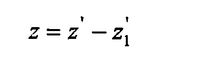
- Next, the distance from the RUs to the origin in the translated coordinate system is calculated:


- Then a matrix of RU coordinate values is developed:

- Next, a new vector combining the TDOAs and the RU ranges is developed:


- Recall that the coordinates of the RUs were translated at the beginning of the process such that RU1 was at the origin. Therefore it is necessary to translate the position estimate to the original coordinate system for the final position estimate:

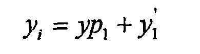

- The output of the Two-Dimensional Closed Form Range Aided Algorithm is the position estimate (xi, yi, zi).
- The input to the Two-Dimensional MLE Range Aided Algorithm consist of:
- RU coordinates
- Associated measured TOAs
- Initial Position Estimate (xi, yi, zi)
- Range Measurement (Rm )
- RU from which measured range
- The output from the Two-Dimensional MLE Range Aided Algorithm is a precise location of the target in x, y, z form.
- Again, the first step is to order the RUs in the algorithm such that RU1 is the RU from which the range was measured. The Two-Dimensional MLE Range Aided Algorithm is an iterative solution that requires an initial guess (xi, yi, zi position estimate) to start and continuously approximates a new position estimate. Expected TOAs are calculated for each new position estimate and the cost function of the Two-Dimensional MLE Range Aided Algorithm measures the error between the calculated TOAs and the measured TOAs. For calculation of the final position, the cost function is defined to be the norm of the difference between the expected TOAs derived from the current position estimate (xi, yi, zi) and the measured TOAs. Again, the range is included to improve the accuracy of the final calculated position of the target. The Two-Dimensional MLE Range Aided Algorithm is iterated until subsequent estimates are sufficiently close together that the cost function returns a value equal to or less than a predetermined value.


- Another embodiment of the present invention will now be described with reference to
Figs. 1-2 and11-12 . As in the previous embodiments, a number of RUs are placed in known positions within the airport confines as shown inFig. 1 . However, in this embodiment any combination of at least four receivers and one transmitter is required to provide three-dimensional localization of targets in and around the airport. Again, the RUs can receive only, transmit only, or both transmit and receive and additional RUs may be required to overcome Line of Sight (LOS) obstructions and multipath issues. - As in the previous embodiments each RU includes a
TOA device 2 to provide an accurate time stamp of the Time of Arrival (TOA) of each transponder signal received from a target. The RUs 1 are connected by a communication means to aprocessing unit 3. The signal flow between a transmitter/receiver RU 4, atarget 5 and three receiver RUs 6 is shown inFig. 11 . Theinterrogation signal 7 is sent from the transmitter/receiver RU 4 to solicit areply 8 from the target's 5 transponder. Transmitter/receiver RU 4 records the time of the transmission of theinterrogation signal 7 for later use in calculating the target's range. The transponder inside the target replies automatically within a known amount of time subject to a tolerance as previously described. The reply signal is received at all of the RUs 4, 6, 6, 6 where the data is decoded and time tagged with its Time of Arrival (TOA) from theTOA device 2. Each RU then sends the data with its time stamp over a data link to theprocessing unit 3 for further evaluation. Additionally, the transmitter/receiver RU 4 provides the time of transmission of theinterrogation signal 7 over the data link to theprocessing unit 3. - The processing unit clusters the decoded data with each cluster containing a specific transmission received at each RU from a specific target. Clustering is typically performed through target number identification, Mode S address, or
Mode 3/A Code; however other proven methods are also available. As will be explained below in more detail, the processing unit then performs calculations utilizing the target data and recorded transmission time of the interrogation signal provided by the RUs to determine the precise location of the target. - The next step is to determine whether the target's range can be used in the position estimate calculation. A range threshold check is performed due to variations in the processing times of the target's transponder as previously described. To determine the target's three-dimensional position using the range calculated from the RTD data in accordance with this embodiment of the present invention, the coordinates of the RUs that received the signals, the measured TOAs, the calculated range and the RU from which the range was measured are input to the Three-Dimensional Closed Form Range Aided Algorithm of the present invention. The Three-Dimensional Closed Form Range Aided Algorithm provides an estimate of the target's position in a Cartesian coordinate system as x, y, z data and is similar to the Two-Dimensional Closed Form Range Aided Algorithm as will be seen in the following description.
- The algorithm first orders the RU coordinates and their associated TOAs so as to set RU1 in the algorithm as the RU from which the range is measured. This is significant in that the TOAs from the remaining RUs are then subtracted from the TOA of RU1 for calculating the Time Differential of Arrivals (TDOAs) used to calculate the position estimate. The coordinates of the RUs are then translated such that RU1 is at the origin of the Cartesian coordinate system and the distance from the remaining RUs to the new origin (RU1) is calculated. A matrix of RU position values is developed and a new vector that combines the TDOAs and the RU ranges is calculated from which the position estimate is directly available. The position estimate at this point is in a Cartesian coordinate system with RU1 at the origin so it is necessary to translate back to the original Cartesian coordinate system with the system center at the origin for the final position estimate of the target in x, y, z form.
- The position estimate from the Three-Dimensional Closed Form Range Aided Algorithm is further refined through the Three-Dimensional MLE (Maximum Likelihood Position Estimate) Range Aided Algorithm. The Three-Dimensional MLE Range Aided Algorithm requires, as inputs, the initial position estimate of the target, coordinates of the RUs, associated measured TOAs, range measurement and RU from which the range was measured (RU1). The Three-Dimensional MLE Range Aided Algorithm is an iterative solution that continuously approximates a new position estimate and calculates expected TOAs corresponding to the new position estimates. The Three-Dimensional MLE Range Aided Algorithm further includes a cost function that measures the error between calculated TOAs and the measured TOAs. For the position estimate calculation, the cost function is defined to be the norm between expected TOAs corresponding to the position estimate and the measured TOAs with the range measurement included as will be more specifically described later. Other search function evaluation methods such as the Newton-Raphson Method and Simplex Downhill Method can be used with results similar in accuracy.
-
Fig. 12 shows a flow diagram of the steps in accordance with this embodiment of the present invention. The first step is to arrange a minimum of four antenna elements (RUs), preferably within the confines of an airport. At least one of the antenna elements must be both transmit and receive capable (transmitter/receiver RU), whereas the remaining elements can be receiver-only RUs. - The transmitter/receiver RU transmits an interrogation signal to the target and records the time of transmission. The target's transponder transmits a reply signal with known data (e.g., Mode S address, aircraft identification, altitude, etc.). The RU that transmitted the interrogation signal and at least three additional RUs not subject to line of sight or multipath issues receive the reply. The received data is decoded and time-tagged with the TOA information. The received data, TOA, and recorded transmission time of the interrogation signal are then sent to
processing unit 3. Theprocessing unit 3 clusters the target data such that a cluster contains information from a single transmission by the same target received by multiple RUs. - To calculate the three-dimensional position, a determination is first made whether to utilize the range calculated from the RTD data to improve the accuracy of the position estimate. If the determination is made to utilize the range in the calculation then the three-dimensional position estimate is calculated using the Three-Dimensional Closed Form Range Aided Algorithm of the present invention. The three-dimensional position estimate is further refined through the Three-Dimensional MLE Range Aided Algorithm.
- The three-dimensional range aided algorithms will now be described in detail.
- The inputs to the Three-Dimensional Closed Form Range Aided Algorithm include: .
- RU coordinates
- Associated measured TOAs
- Measured range (R)
- RU from which Range was measured (RUr)
- The output from the Three-Dimensional Closed Form Range Aided Algorithm is an estimate of the target's position.
- The first step is to order the RU coordinates and their associated TOAs in the algorithm such that RU1 is the RU from which the range is measured. The next step is to calculate Time Difference of Arrivals (TDOAs) using the first Time of Arrival (from RU1) as the reference:


- Next, the RU coordinates are translated such that RU1 is at the origin:


- Next, the distance from the RUs to the origin in the translated coordinate system is calculated:


- Then a matrix of RU coordinate values is developed:

- Next, a new vector combining the TDOAs and the RU ranges is developed:




- Recall that the coordinates of the RUs were translated at the beginning of the process such that RU1 was at the origin. Therefore it is necessary to translate the position estimate to the original coordinate system for the fmal position estimate:


- The output of the Three-Dimensional Closed Form Range Aided Algorithm is the position estimate (xi, yi, zi) of the target.
- The inputs to the Three-Dimensional MLE Range Aided Algorithm consist of:
- RU coordinates
- Associated measured TOAs
- Initial Position Estimate (xi, yi, zi)
- Range Measurement (Rm )
- Associated RU from which range was measured
- The output from the Three-Dimensional MLE Range Aided Algorithm is a precise location of the target in x, y, z form.
- As with the Three-Dimensional Closed Form Range Aided Algorithm, the first step is to order the RUs in the algorithm such that RU1 is the RU from which the range is measured. The Three-Dimensional MLE Range Aided Algorithm is an iterative solution that requires an initial guess (xi, yi, zi position estimate) to start and continuously approximates a new position estimate. Expected TOAs are calculated for each new position estimate and the cost function of the Three-Dimensional MLE Range Aided Algorithm measures the error between the calculated TOAs and the measured TOAs. For the calculation of the final position, the cost function is defined to be the norm of the difference between the expected TOAs derived from the current position estimate (xi, yi, zi) and the measured TOAs. The range is included to improve the accuracy of the final calculated position of the target. The Three-Dimensional MLE Range Aided Algorithm is iterated until subsequent estimates are sufficiently close together that the cost function returns a value equal to or less than a predetermined minimum:


- As can be seen, this invention can be particularly useful to airports that do not have, and cannot afford an expensive radar system. Additionally, this invention can be used to greatly extend the effective range of current air traffic surveillance systems without the requirement of additional transmitting antennas or RUs placed outside the system boundaries.


Claims (50)
- A method of locating a target, comprising the steps of:receiving a signal from the target (5) using at least three receivers (4, 6, 60); determining the Time of Arrival (TOA) of the signals at each receiver (4, 6, 60); calculating a measured Time Differential of Arrival (TDOA) using the TOA from each receiver (4, 6, 60);characterized by transmitting a signal (7) from a single transmitter (4, 40) to a target (5); receiving a return signal (8) from the target (5) using at least one receiver (4, 60) of said at least three receivers (4, 6, 60);calculating the round trip delay (RTD) from the transmitter (4, 40) to the target (5) to said at least one receiver (4, 60): andusing the measured TDOA and the RTD data to calculate at least a position estimate of the target.
- A method of locating a target, according to claim 1, wherein the step of calculating at least a position estimate of the target further includes the steps of:calculating an initial azimuth of the target using the measured TDOA data; andusing the initial azimuth and the RTD data to calculate at least an approximate plane position of the target.
- The method of claim 2, wherein height is calculated from altitude data provided in the return signal from the target, such that the initial azimuth and RTD data combined with the height are used to calculate the approximate three-dimensional position of the target
- The method of claim 2, wherein transmission and reception of the signal is performed through the same antenna, such-that the RTD data indicates the range of the target from the transmitter.
- The method of claim 4, wherein said at least one receiver also functions as one of said at least three receivers.
- The method of claim 1, wherein said signal received by said at least three receivers is said return signal.
- The method of claim 2, wherein said signal received by said at least three receivers is said return signal.
- The method of claim 4, further comprising the steps of:using the initial azimuth and RTD data to define an arc on which the target is located;selecting a predetermined number of points along said arc;calculating the expected TDOA for each point;comparing the expected TDOA for each point to said measured TDOA to determine a minimum error between the expected TDOA of each point and said measured TDOA; andselecting the azimuth associated with the expected TDOA having the minimum error as a more precise azimuth of the target; andusing the more precise azimuth and the RTD data to calculate a more precise plane position of the target.
- The method of claim 8, wherein each point arranged along said arc has the same RTD.
- The method of claim 8, wherein said transmitter and said receivers are arranged in an array having an array baseline, and the length of said arc is approximately twice the length of said array baseline.
- The method of claim 8, further comprising the steps of:using said more precise azimuth and RTD data to define a segment of said arc;selecting a second set of a predetermined number of points along said segment of said arc;calculating the expected TDOA for each point within said second set;comparing the expected TDOA for each point within said second set to said measured TDOA to determine a minimum error between the expected TDOA of each point in said second set and said measured TDOA; andselecting the azimuth associated with the expected TDOA having the minimum error as an even a more precise azimuth of the target; andusing the even more precise azimuth and the RTD data to calculate an even more precise plane position of the target.
- A system for locating a target, comprising:at least three receivers (4, 6) for receiving a signal from the target (5); a mechanism for determining the Time of Arrival (TOA) of the signals at each receiver (4, 6);a mechanism (3) for calculating a measured Time Differential of Arrival (TDOA) using the TOA from each receiver (4, 6);a mechanism (3) for calculating an initial azimuth of the target (5) using the measured TDOA data;characterized bya transmitter/receiver receiving unit (4) for transmitting a signal (7) to a target (5) and for receiving a return signal (8) from the target (5) whereby the receiver of the transmitter/receiver RU is one receiver of said at least three receivers; and bya mechanism for calculating the round trip delay (RTD) from the transmitter of the transmitter/receiver RU (4) to the target (5) to the receiver of the transmitter/receiver RU (4); anda mechanism for calculating at least a position estimate of the target (5) using the initial azimuth and the RTD data.
- The system of claim 12, wherein height is calculated from altitude data provided in the return signal from the target, such that the initial azimuth and RTD data combined with the height are used to calculate the approximate three-dimensional position of the target.
- The system of claim 12, wherein transmission and reception of the signal is performed through the same antenna, such that the RTD data indicates the range of the target from the transmitter.
- The system of claim 14, wherein said at least one receiver also functions as one of said at least three receivers.
- The system of claim 14, further comprising:a mechanism for defining an arc on which the target is located using the initial azimuth and RTD data;a mechanism for selecting a predetermined number of points along said arc;a mechanism for calculating the expected TDOA for each point;a mechanism for comparing the expected TDOA for each point to said measured TDOA to determine a minimum error between the expected TDOA of each point and said measured TDOA; anda mechanism for selecting the azimuth associated with the expected TDOA having the minimum error as a more precise azimuth of the target; anda mechanism for calculating a more precise plane position of the target using the more precise azimuth and the RTD data.
- The system of claim 16, wherein said points selected along said arc have the same RTD.
- The system of claim 16, wherein said transmitter and said receivers are arranged in an array having an array baseline, and the length of said arc is defined to be approximately twice the length of said array baseline.
- The system of claim 16, further comprising:a mechanism for defining a segment of said arc using said more precise azimuth and RTD data;a mechanism for selecting a second set of a predetermined number of points along said segment of said arc;a mechanism for calculating the expected TDOA for each point within said second set;a mechanism for comparing the expected TDOA for each point within said second set to said measured TDOA to determine a minimum error between the expected TDOA of each point in said second set and said measured TDOA; anda mechanism for selecting the azimuth associated with the expected TDOA having the minimum error as even a more precise azimuth of the target; anda mechanism for calculating an even more precise plane position of the target using the even more precise azimuth and the RTD data.
- The method of claim 1, wherein said at least one receiver also functions as one of said at least three receivers.
- The method of claim 1, wherein said signal received by said at least three receivers is said return signal.
- The method of claim 1, wherein transmission and reception of the signal is performed through the same antenna, such that the RTD data indicates the range of the target from the transmitter.
- The method of claim 1, wherein the position estimate, coordinates of said receivers, the TOAs and the RTD data are used to calculate a more precise position of the target.
- The method of claim 23, wherein the more precise position is calculated by the steps of:a) estimating a new target position;b) calculating TOAs that correspond to the new target position;c) measuring the error between the calculated TOAs and the measured TOAs; andd) selecting the position estimate associated with the expected TOAs having the minimum error as the new position estimate of the target.
- The method of claim 24, wherein steps a-d are repeated until the difference between the calculated TOAs and the measured TOAs is at least one of less than and equal to a predetermined value.
- The method of claim 24, wherein the more precise position is calculated using a maximum likelihood algorithm.
- The method of claim 26, wherein the maximum likelihood algorithm is the Newton-Raphson method.
- The method of claim 26, wherein the maximum likelihood algorithm is the Simplex Downhill method.
- The method of claim 1, wherein the height of the target is known and combined with the TDOA and the RTD data to calculate a position estimate of the target.
- The method of claim 29, wherein the height is calculated from altitude data included in the reply signal from the target.
- The method of claim 29, wherein the height is known from the determination that the target is on the ground.
- The method of claim 29, wherein the position estimate, coordinates of the receivers, the TOAs, the height of the target and the RTD data are used to calculate a more precise position of the target.
- The method of claim 32, wherein the more precise position is calculated by the steps of:a) estimating a new target position;b) calculating TOAs that correspond to the new target position;c) measuring the error between the calculated TOAs and the measured TOAs; andd) selecting the position estimate associated with the expected TOA having the minimum error as the new position estimate of the target.
- The method of claim 33, wherein steps a-d are repeated until the difference between the calculated TOAs and the measured TOAs is at least one of less than and equal to a predetermined value.
- The method of claim 33, wherein the more precise position is calculated using a maximum likelihood algorithm.
- The method of claim 35, wherein the maximum likelihood algorithm is the Newton-Raphson method.
- The method of claim 35, wherein the maximum likelihood algorithm is the Simplex Downhill method.
- A system for locating a target, comprising:at least three receivers (60) for receiving a signal from the target (5);a mechanism for determining the Time of Arrival (TOA) of the signals at each receiver (60);a mechanism for calculating a measured Differential Time of Arrival (TDOA) using the TOA from each receiver (60);characterized bya single transmitter (40) for transmitting a signal (7) to a target (5);at least one receiver (60) of said at least three receivers (60) for receiving a return signal (8) from the target (5);a mechanism for calculating the round trip delay (RTD) from said transmitter (40) to the target (5) to said receiver (60) anda mechanism for using the measured TDOA and the RTD data to calculate at least a position estimate of the target (5)
- The system of claim 38, wherein said at least one receiver also functions as one of said at least three receivers.
- The method of claim 38, wherein transmission and reception of the signal is performed through the same antenna, such that the RTD data indicates the range of the target from the transmitter.
- The system of claim 38, further comprising a mechanism for calculating a more precise position of the target using the position estimate, coordinates of said receivers, the TOAs and the RTD data.
- The system 41, further comprising a mechanism for:a) estimating a new target position;b) calculating TDOAs that correspond to the new target position;c) measuring the error between the calculated TOAs and the measured TOAs; andd) selecting the position estimate associated with the expected TOA having the minimum error as the new position estimate of the target.
- The method of claim 42, further comprising a mechanism for repeating steps a-d until the difference between the calculated TOAs and the measured TOAs is at least one of less than and equal to a predetermined value.
- The system of claim 38, further comprising a mechanism for determining the height of the target.
- The system of claim 44, wherein the height is calculated from altitude data included in the reply signal from the target.
- The system of claim 44, further comprising a mechanism for determining that the target is on the ground.
- The system of claim 44, further comprising a mechanism for calculating a position estimate of the target using the TDOA, the height of the target and the RTD data.
- The system of claim 47, further comprising a mechanism for calculating a more precise position of the target using the position estimate, coordinates of the receivers, the TOAs, the height of the target and the RTD data.
- The system 48, further comprising a mechanism for:a) estimating a new target position;b) calculating TOAs that correspond to the new target position;c) measuring the error between the calculated TOAs to the measured TOAs; andd) selecting the position estimate associated with the expected TOA having the minimum error as the new position estimate of the target.
- The method of claim 49, further comprising a mechanism for repeating steps a-d until the difference between the calculated TOAs and the measured TOAs is at least one of less than and equal to a predetermined value.
Priority Applications (1)
| Application Number | Priority Date | Filing Date | Title |
|---|---|---|---|
| PL04786473T PL1654561T3 (en) | 2003-08-14 | 2004-08-09 | Target localization using tdoa distributed antenna |
Applications Claiming Priority (3)
| Application Number | Priority Date | Filing Date | Title |
|---|---|---|---|
| US49496303P | 2003-08-14 | 2003-08-14 | |
| US50599703P | 2003-09-25 | 2003-09-25 | |
| PCT/US2004/025629 WO2005017555A2 (en) | 2003-08-14 | 2004-08-09 | Target localization using tdoa distributed antenna |
Publications (3)
| Publication Number | Publication Date |
|---|---|
| EP1654561A2 EP1654561A2 (en) | 2006-05-10 |
| EP1654561B1 true EP1654561B1 (en) | 2012-07-25 |
| EP1654561B8 EP1654561B8 (en) | 2012-09-05 |
Family
ID=34198017
Family Applications (1)
| Application Number | Title | Priority Date | Filing Date |
|---|---|---|---|
| EP04786473A Revoked EP1654561B8 (en) | 2003-08-14 | 2004-08-09 | Target localization using tdoa distributed antenna |
Country Status (9)
| Country | Link |
|---|---|
| US (1) | US7170441B2 (en) |
| EP (1) | EP1654561B8 (en) |
| JP (1) | JP4644197B2 (en) |
| AU (1) | AU2004265974B2 (en) |
| CA (1) | CA2532050C (en) |
| DK (1) | DK1654561T3 (en) |
| PL (1) | PL1654561T3 (en) |
| PT (1) | PT1654561E (en) |
| WO (1) | WO2005017555A2 (en) |
Families Citing this family (122)
| Publication number | Priority date | Publication date | Assignee | Title |
|---|---|---|---|---|
| US6448929B1 (en) * | 1998-07-14 | 2002-09-10 | Rannoch Corporation | Method and apparatus for correlating flight identification data with secondary surveillance radar data |
| US7612716B2 (en) | 1999-03-05 | 2009-11-03 | Era Systems Corporation | Correlation of flight track data with other data sources |
| US7782256B2 (en) | 1999-03-05 | 2010-08-24 | Era Systems Corporation | Enhanced passive coherent location techniques to track and identify UAVs, UCAVs, MAVs, and other objects |
| US7908077B2 (en) * | 2003-06-10 | 2011-03-15 | Itt Manufacturing Enterprises, Inc. | Land use compatibility planning software |
| US7739167B2 (en) | 1999-03-05 | 2010-06-15 | Era Systems Corporation | Automated management of airport revenues |
| US8446321B2 (en) | 1999-03-05 | 2013-05-21 | Omnipol A.S. | Deployable intelligence and tracking system for homeland security and search and rescue |
| US20100079342A1 (en) * | 1999-03-05 | 2010-04-01 | Smith Alexander E | Multilateration enhancements for noise and operations management |
| US7889133B2 (en) * | 1999-03-05 | 2011-02-15 | Itt Manufacturing Enterprises, Inc. | Multilateration enhancements for noise and operations management |
| US7777675B2 (en) | 1999-03-05 | 2010-08-17 | Era Systems Corporation | Deployable passive broadband aircraft tracking |
| US7576695B2 (en) * | 1999-03-05 | 2009-08-18 | Era Systems Corporation | Multilateration enhancements for noise and operations management |
| US7570214B2 (en) * | 1999-03-05 | 2009-08-04 | Era Systems, Inc. | Method and apparatus for ADS-B validation, active and passive multilateration, and elliptical surviellance |
| US8203486B1 (en) | 1999-03-05 | 2012-06-19 | Omnipol A.S. | Transmitter independent techniques to extend the performance of passive coherent location |
| US7667647B2 (en) | 1999-03-05 | 2010-02-23 | Era Systems Corporation | Extension of aircraft tracking and positive identification from movement areas into non-movement areas |
| EP1430740A1 (en) * | 2002-02-15 | 2004-06-23 | Nokia Corporation | Positioning in a telecommunications system |
| PT1654561E (en) * | 2003-08-14 | 2012-10-24 | Saab Sensis Corp | Target localization using tdoa distributed antenna |
| US9020854B2 (en) | 2004-03-08 | 2015-04-28 | Proxense, Llc | Linked account system using personal digital key (PDK-LAS) |
| US7411551B2 (en) * | 2004-06-21 | 2008-08-12 | Korea Electrotechnology Research Institute | System and method for asynchronous wireless positioning by ordered transmission |
| EP1788040B1 (en) * | 2004-08-06 | 2012-06-06 | Mitsubishi Gas Chemical Company, Inc. | Insulated ultrafine powder and high dielectric constant resin composite material |
| WO2006069330A2 (en) | 2004-12-20 | 2006-06-29 | Proxense, Llc | Biometric personal data key (pdk) authentication |
| US7720598B2 (en) * | 2005-03-31 | 2010-05-18 | Deere & Company | System and method for determining a position of a vehicle with compensation for noise or measurement error |
| US7647177B2 (en) * | 2005-03-31 | 2010-01-12 | Deere & Company | System and method for determining a position of a vehicle |
| US7653483B2 (en) * | 2005-03-31 | 2010-01-26 | Deere & Company | System and method for determining a position of a vehicle |
| BRPI0611383A2 (en) * | 2005-05-06 | 2010-09-08 | Orthosoft Inc | RF system to track objects |
| US7616149B2 (en) * | 2005-09-28 | 2009-11-10 | Raytheon Company | Methods and apparatus for radar time sensor |
| US10281557B2 (en) | 2005-12-15 | 2019-05-07 | Polte Corporation | Partially synchronized multilateration/trilateration method and system for positional finding using RF |
| US10834531B2 (en) | 2005-12-15 | 2020-11-10 | Polte Corporation | Multi-path mitigation in rangefinding and tracking objects using reduced attenuation RF technology |
| US20110205121A1 (en) * | 2005-12-28 | 2011-08-25 | Camero-Tech Ltd. | Method of determining real time location of reflecting objects and system thereof |
| US11206664B2 (en) | 2006-01-06 | 2021-12-21 | Proxense, Llc | Wireless network synchronization of cells and client devices on a network |
| US8036152B2 (en) | 2006-01-06 | 2011-10-11 | Proxense, Llc | Integrated power management of a client device via system time slot assignment |
| US7420501B2 (en) * | 2006-03-24 | 2008-09-02 | Sensis Corporation | Method and system for correlating radar position data with target identification data, and determining target position using round trip delay data |
| US8412949B2 (en) | 2006-05-05 | 2013-04-02 | Proxense, Llc | Personal digital key initialization and registration for secure transactions |
| US7965227B2 (en) * | 2006-05-08 | 2011-06-21 | Era Systems, Inc. | Aircraft tracking using low cost tagging as a discriminator |
| US7577446B2 (en) * | 2006-08-03 | 2009-08-18 | Ntt Docomo, Inc. | Weighted least square localization method exploiting multipath channel statistics for non-line-of-sight mitigation |
| JP2008039738A (en) * | 2006-08-10 | 2008-02-21 | Fujitsu Ltd | Positioning method |
| JP4980021B2 (en) * | 2006-09-29 | 2012-07-18 | 三菱電機株式会社 | Positioning system, detection device, positioning device, positioning system positioning method, detection device detection method, positioning device positioning method, detection device detection program, and positioning device positioning program |
| US9269221B2 (en) | 2006-11-13 | 2016-02-23 | John J. Gobbi | Configuration of interfaces for a location detection system and application |
| GB0711531D0 (en) * | 2007-06-15 | 2007-07-25 | Qinetiq Ltd | Radar coordinate registration |
| JP4833175B2 (en) * | 2007-09-21 | 2011-12-07 | 日本電信電話株式会社 | Position information detection device provided in a flying object |
| KR100946988B1 (en) * | 2007-10-08 | 2010-03-10 | 전자부품연구원 | Apparatus and method for collaborative location recognition using maximum likelihood estimation including weights |
| TWI348555B (en) * | 2007-10-30 | 2011-09-11 | Univ Nat Taiwan | Target detection device and its detection method |
| WO2009062194A1 (en) * | 2007-11-09 | 2009-05-14 | Proxense, Llc | Proximity-sensor supporting multiple application services |
| US8171528B1 (en) | 2007-12-06 | 2012-05-01 | Proxense, Llc | Hybrid device having a personal digital key and receiver-decoder circuit and methods of use |
| US9251332B2 (en) | 2007-12-19 | 2016-02-02 | Proxense, Llc | Security system and method for controlling access to computing resources |
| WO2009102979A2 (en) | 2008-02-14 | 2009-08-20 | Proxense, Llc | Proximity-based healthcare management system with automatic access to private information |
| US11120449B2 (en) | 2008-04-08 | 2021-09-14 | Proxense, Llc | Automated service-based order processing |
| JPWO2009145325A1 (en) * | 2008-05-29 | 2011-10-20 | 株式会社日立製作所 | Mobile body relative position detection system and mobile body performing relative position detection |
| IT1391337B1 (en) | 2008-08-07 | 2011-12-05 | Univ Roma | INTEGRATED RADIO-ELECTRIC LOCATION SYSTEM BASED ON NOISY OF WAVE |
| US8354951B2 (en) * | 2009-05-07 | 2013-01-15 | Intelligent Sciences, Ltd. | Short baseline helicopter positioning radar for low visibility |
| WO2010138696A1 (en) * | 2009-05-27 | 2010-12-02 | Sensis Corporation | System and method for passive range-aided multilateration using time lag of arrival (tloa) measurements |
| FR2949867B1 (en) * | 2009-09-04 | 2012-04-27 | Thales Sa | MULTIFUNCTION AIRBORNE RADAR DEVICE WITH BROADBAND LARGE ANGULAR COVERAGE FOR DETECTION AND TRACKING, IN PARTICULAR FOR A DETECTION AND EVACUATION FUNCTION |
| US9418205B2 (en) | 2010-03-15 | 2016-08-16 | Proxense, Llc | Proximity-based system for automatic application or data access and item tracking |
| CN102884440B (en) * | 2010-03-17 | 2016-04-13 | 霍尼韦尔国际公司 | For Short baseline, the system and method determining airborne aircraft position at low cost |
| US8918854B1 (en) | 2010-07-15 | 2014-12-23 | Proxense, Llc | Proximity-based system for automatic application initialization |
| US8995227B1 (en) * | 2010-08-15 | 2015-03-31 | Shotspotter, Inc. | Systems and methods of processing information regarding weapon fire location using projectile shockwave and muzzle blast times of arrival data |
| US8857716B1 (en) | 2011-02-21 | 2014-10-14 | Proxense, Llc | Implementation of a proximity-based system for object tracking and automatic application initialization |
| KR101836427B1 (en) * | 2011-04-29 | 2018-03-09 | 오소트론 주식회사 | Ranging Method and Apparatus, and Positioning Method |
| US8493263B2 (en) * | 2011-06-28 | 2013-07-23 | Intelligent Sciences, Ltd. | Short baseline helicopter positioning radar for low visibility using combined phased array and phase difference array receivers |
| EP2734857B1 (en) * | 2011-07-20 | 2019-01-23 | Commonwealth Scientific & Industrial Research Organisation ( C.S.I.R.O. ) | Wireless localisation system |
| US11835639B2 (en) | 2011-08-03 | 2023-12-05 | Qualcomm Technologies, Inc. | Partially synchronized multilateration or trilateration method and system for positional finding using RF |
| US11125850B2 (en) | 2011-08-03 | 2021-09-21 | Polte Corporation | Systems and methods for determining a timing offset of emitter antennas in a wireless network |
| US8521181B2 (en) * | 2011-09-19 | 2013-08-27 | Qualcomm Incorporated | Time of arrival based positioning system |
| JPWO2013136648A1 (en) * | 2012-03-14 | 2015-08-03 | 日本電気株式会社 | Wide area multilateration system, central office, and two-dimensional position calculation method used therefor |
| US8949012B2 (en) | 2012-04-05 | 2015-02-03 | Her Majesty The Queen In Right Of Canada, As Represented By The Minister Of National Defence | Automated multi-vehicle position, orientation and identification system and method |
| US10845453B2 (en) | 2012-08-03 | 2020-11-24 | Polte Corporation | Network architecture and methods for location services |
| US10440512B2 (en) | 2012-08-03 | 2019-10-08 | Polte Corporation | Angle of arrival (AOA) positioning method and system for positional finding and tracking objects using reduced attenuation RF technology |
| US10863313B2 (en) | 2014-08-01 | 2020-12-08 | Polte Corporation | Network architecture and methods for location services |
| US20140097988A1 (en) * | 2012-10-05 | 2014-04-10 | Qualcomm Incorporated | Speed estimation using delta rtt measurements and area maps |
| WO2014087683A1 (en) | 2012-12-05 | 2014-06-12 | 三菱電機株式会社 | Positioning and tracking device |
| CN110895326B (en) * | 2012-12-12 | 2024-03-22 | 高通科技公司 | Method for determining the position of a user equipment in a wireless system |
| US20140225780A1 (en) * | 2013-02-11 | 2014-08-14 | The State of Oregon acting by and through the State Board of Higher Education on behalf of Orego | Using time-difference-of-arrival to detect a position of a target transmitter |
| US9405898B2 (en) | 2013-05-10 | 2016-08-02 | Proxense, Llc | Secure element as a digital pocket |
| DE102013209235A1 (en) * | 2013-05-17 | 2014-11-20 | Siemens Aktiengesellschaft | Method and device for position determination |
| US9191912B2 (en) | 2013-09-26 | 2015-11-17 | Adc Telecommunications, Inc. | Systems and methods for location determination |
| US9807569B2 (en) * | 2014-02-17 | 2017-10-31 | Ubiqomm, Inc | Location based services provided via unmanned aerial vehicles (UAVs) |
| US9859972B2 (en) | 2014-02-17 | 2018-01-02 | Ubiqomm Llc | Broadband access to mobile platforms using drone/UAV background |
| US9479964B2 (en) | 2014-04-17 | 2016-10-25 | Ubiqomm Llc | Methods and apparatus for mitigating fading in a broadband access system using drone/UAV platforms |
| CN104053231B (en) * | 2014-06-17 | 2017-09-29 | 京信通信系统(中国)有限公司 | Real-time location method and system |
| US9614608B2 (en) | 2014-07-14 | 2017-04-04 | Ubiqomm Llc | Antenna beam management and gateway design for broadband access using unmanned aerial vehicle (UAV) platforms |
| CN105830510A (en) * | 2014-09-26 | 2016-08-03 | Adc电信公司 | Systems and methods for location determination |
| US9571180B2 (en) * | 2014-10-16 | 2017-02-14 | Ubiqomm Llc | Unmanned aerial vehicle (UAV) beam forming and pointing toward ground coverage area cells for broadband access |
| US9712228B2 (en) | 2014-11-06 | 2017-07-18 | Ubiqomm Llc | Beam forming and pointing in a network of unmanned aerial vehicles (UAVs) for broadband access |
| US9660718B2 (en) | 2015-05-13 | 2017-05-23 | Ubiqomm, LLC | Ground terminal and UAV beam pointing in an unmanned aerial vehicle (UAV) for network access |
| US9590720B2 (en) | 2015-05-13 | 2017-03-07 | Ubiqomm Llc | Ground terminal and gateway beam pointing toward an unmanned aerial vehicle (UAV) for network access |
| JP6692129B2 (en) * | 2015-07-10 | 2020-05-13 | ルネサスエレクトロニクス株式会社 | Semiconductor device |
| CN105158730B (en) * | 2015-08-14 | 2017-07-18 | 上海交通大学 | TDOA localization methods based on MDS subspaces the 4th and the 5th characteristic vector |
| EP3193191B1 (en) * | 2016-01-15 | 2019-09-18 | Fraunhofer-Gesellschaft zur Förderung der angewandten Forschung e.V. | Method and system for measuring location and/or orientation |
| KR101760392B1 (en) * | 2016-04-27 | 2017-07-21 | 국방과학연구소 | Distributed mimo radar system and method of target position estimation thereof |
| US9853713B2 (en) | 2016-05-06 | 2017-12-26 | Ubiqomm Llc | Unmanned aerial vehicle (UAV) beam pointing and data rate optimization for high throughput broadband access |
| WO2017208277A1 (en) * | 2016-05-31 | 2017-12-07 | 日本電気株式会社 | Moving body position measurement system, central station, query control method for same, and program |
| KR101881868B1 (en) * | 2016-07-15 | 2018-07-25 | 국방과학연구소 | A Method for Target Localization by Stochastic Selection of Collected Information for Pulse Signal |
| JP2018048812A (en) * | 2016-09-19 | 2018-03-29 | 国立研究開発法人 海上・港湾・航空技術研究所 | Searching system, searching arithmetic device, and searching method |
| US10313686B2 (en) | 2016-09-20 | 2019-06-04 | Gopro, Inc. | Apparatus and methods for compressing video content using adaptive projection selection |
| JP2018054493A (en) * | 2016-09-29 | 2018-04-05 | 太陽誘電株式会社 | Millimeter wave radar and millimeter wave radar detection method |
| KR101911325B1 (en) * | 2016-11-17 | 2018-10-25 | 한국기계연구원 | Space Coordinate Measurement System and Method of Space Coordinate Measurement Using the Same |
| EP3415946B1 (en) * | 2017-06-13 | 2021-08-04 | Swiss Timing Ltd. | Method for calculating a position of a transponder within an area of interest |
| EP3415934B1 (en) * | 2017-06-13 | 2024-07-24 | Swiss Timing Ltd. | Method for estimating the covered area of a directive antenna of a local positioning system while setting up said system |
| KR101988109B1 (en) * | 2017-06-30 | 2019-06-11 | 한양대학교 산학협력단 | Method for estimating position of signal source using distance estimation in mimo system |
| US11280912B2 (en) | 2018-01-12 | 2022-03-22 | The Regents Of The University Of Colorado | Hybrid interference localization |
| US11255945B2 (en) | 2018-03-27 | 2022-02-22 | Polte Corporation | Multi-path mitigation in tracking objects using compressed RF data |
| JP7099161B2 (en) * | 2018-08-10 | 2022-07-12 | 株式会社Soken | Portable device position estimation system |
| CN109407084B (en) * | 2018-08-30 | 2023-05-05 | 河海大学 | Radar target positioning method based on Chan improved algorithm and data fusion |
| EP3671255A1 (en) * | 2018-12-20 | 2020-06-24 | FREQUENTIS COMSOFT GmbH | Method for determining the location of a plurality of targets |
| EP3928118A4 (en) * | 2019-02-24 | 2022-11-16 | Locix Inc. | Systems and methods for precise radio frequency localization using time sweep time difference of arrival |
| IT201900004801A1 (en) | 2019-03-29 | 2020-09-29 | Elett 80 S P A | Method for locating a moving target in an automated warehouse |
| CN110082718B (en) * | 2019-04-24 | 2023-07-28 | 武汉大数智联科技有限公司 | High-precision distributed AOA positioning system and method |
| US11226396B2 (en) | 2019-06-27 | 2022-01-18 | Gracenote, Inc. | Methods and apparatus to improve detection of audio signatures |
| CN110412505B (en) * | 2019-06-28 | 2023-08-29 | 同方电子科技有限公司 | Quick time difference positioning grid searching method |
| WO2021030973A1 (en) * | 2019-08-16 | 2021-02-25 | Abb Schweiz Ag | Method and apparatus for determining object location |
| RU2717970C1 (en) * | 2019-10-07 | 2020-03-27 | Федеральное государственное унитарное предприятие "Ростовский-на-Дону научно-исследовательский институт радиосвязи" (ФГУП "РНИИРС") | Method for survey three-coordinate two-position lateration radar ranging of aerospace objects |
| CN111443365B (en) * | 2020-03-27 | 2022-06-17 | 维沃移动通信有限公司 | Positioning method and electronic equipment |
| JP2021183914A (en) * | 2020-05-21 | 2021-12-02 | 株式会社東海理化電機製作所 | Communication device and position estimation method |
| WO2021243609A1 (en) | 2020-06-03 | 2021-12-09 | Zhejiang University | Localizing a target device based on measurements from a measurement device array |
| CN114152910B (en) * | 2020-09-07 | 2024-09-20 | 罗维智联(北京)科技有限公司 | Positioning method and system based on active and passive base station information fusion |
| JP6995326B2 (en) * | 2021-01-19 | 2022-01-14 | 国立研究開発法人 海上・港湾・航空技術研究所 | Radar system and radar search method |
| US11943738B2 (en) * | 2021-03-03 | 2024-03-26 | Qualcomm Incorporated | Shared requirement for a double differential timing procedure |
| CN113255872B (en) * | 2021-05-19 | 2022-11-18 | 河北科技大学 | Chan algorithm-based longicorn stigma exploration positioning method |
| EP4099043A1 (en) | 2021-05-31 | 2022-12-07 | Siemens Aktiengesellschaft | Radio location system and base station and method for locating a transponder for a radio location system |
| EP4123331A1 (en) * | 2021-07-20 | 2023-01-25 | Siemens Aktiengesellschaft | Wireless location system, base station, transponder and method for operating a wireless location system |
| CN113552535B (en) * | 2021-07-21 | 2024-04-09 | 西安邮电大学 | Radio equipment monitoring method and device |
| CN114740428B (en) * | 2022-04-13 | 2024-09-10 | 厦门大学 | Underwater passive positioning method and system based on improved triangle method |
| CN117255404A (en) * | 2022-06-10 | 2023-12-19 | 中兴通讯股份有限公司 | Tunnel positioning method, device, system and storage medium |
| CN115327476B (en) * | 2022-07-23 | 2025-03-21 | 中国人民解放军网络空间部队信息工程大学 | Station deployment method and system under far-field time difference positioning conditions |
Family Cites Families (17)
| Publication number | Priority date | Publication date | Assignee | Title |
|---|---|---|---|---|
| JPS61147984U (en) * | 1985-03-06 | 1986-09-12 | ||
| US4910526A (en) * | 1987-05-18 | 1990-03-20 | Avion Systems, Inc. | Airborne surveillance method and system |
| FR2666904B1 (en) * | 1990-09-18 | 1993-02-12 | Snecma | CONTINUOUS TRANSMISSION RADAR DEVICE FOR THE SHORT-TERM DETERMINATION OF THE RELATIVE POSITION BETWEEN A MISSILE AND A TARGET MACHINE ON WHICH IT IS MOUNTED. |
| JP2743626B2 (en) * | 1991-06-26 | 1998-04-22 | 日本電気株式会社 | Azimuth / distance measuring device |
| JPH09159755A (en) * | 1995-12-06 | 1997-06-20 | Toyo Commun Equip Co Ltd | Secondary radar system |
| JP3204087B2 (en) * | 1996-05-08 | 2001-09-04 | 三菱電機株式会社 | Tracking radar device |
| US5987329A (en) * | 1997-07-30 | 1999-11-16 | Ericsson Inc | System and method for mobile telephone location measurement using a hybrid technique |
| JPH11271418A (en) * | 1998-03-20 | 1999-10-08 | Fujitsu Ltd | Radio position locating system, device and method |
| US6208297B1 (en) * | 1998-10-09 | 2001-03-27 | Cell-Loc Inc. | Methods and apparatus to position a mobile receiver using downlink signals, part I |
| US6873290B2 (en) * | 1999-01-08 | 2005-03-29 | Trueposition, Inc. | Multiple pass location processor |
| US6243648B1 (en) * | 1999-07-12 | 2001-06-05 | Eagle Eye, Inc. | Fast acquisition position reporting system |
| US6300905B1 (en) | 1999-10-05 | 2001-10-09 | Lucent Technologies Inc. | Location finding using a single base station in CDMA/TDMA systems |
| JP2002296335A (en) * | 2001-03-30 | 2002-10-09 | Locus Corp | System of specifying position of mobile terminal |
| US6473694B1 (en) * | 2001-04-06 | 2002-10-29 | Nokia Corporation | Method, apparatus and system for estimating user position with a satellite positioning system in poor signal conditions |
| US6876859B2 (en) * | 2001-07-18 | 2005-04-05 | Trueposition, Inc. | Method for estimating TDOA and FDOA in a wireless location system |
| JP3810323B2 (en) * | 2002-01-28 | 2006-08-16 | 三菱電機株式会社 | Time difference direction detector |
| PT1654561E (en) * | 2003-08-14 | 2012-10-24 | Saab Sensis Corp | Target localization using tdoa distributed antenna |
-
2004
- 2004-08-09 PT PT04786473T patent/PT1654561E/en unknown
- 2004-08-09 PL PL04786473T patent/PL1654561T3/en unknown
- 2004-08-09 JP JP2006523261A patent/JP4644197B2/en not_active Expired - Fee Related
- 2004-08-09 AU AU2004265974A patent/AU2004265974B2/en not_active Expired
- 2004-08-09 CA CA2532050A patent/CA2532050C/en not_active Expired - Lifetime
- 2004-08-09 EP EP04786473A patent/EP1654561B8/en not_active Revoked
- 2004-08-09 DK DK04786473.1T patent/DK1654561T3/en active
- 2004-08-09 US US10/914,530 patent/US7170441B2/en not_active Expired - Lifetime
- 2004-08-09 WO PCT/US2004/025629 patent/WO2005017555A2/en not_active Ceased
Also Published As
| Publication number | Publication date |
|---|---|
| PL1654561T3 (en) | 2013-02-28 |
| WO2005017555A2 (en) | 2005-02-24 |
| PT1654561E (en) | 2012-10-24 |
| HK1107593A1 (en) | 2008-04-11 |
| AU2004265974A1 (en) | 2005-02-24 |
| EP1654561A2 (en) | 2006-05-10 |
| US7170441B2 (en) | 2007-01-30 |
| CA2532050C (en) | 2010-02-23 |
| JP4644197B2 (en) | 2011-03-02 |
| CA2532050A1 (en) | 2005-02-24 |
| JP2007502414A (en) | 2007-02-08 |
| US20050035897A1 (en) | 2005-02-17 |
| EP1654561B8 (en) | 2012-09-05 |
| DK1654561T3 (en) | 2012-10-22 |
| AU2004265974B2 (en) | 2007-08-02 |
| WO2005017555A3 (en) | 2005-04-14 |
Similar Documents
| Publication | Publication Date | Title |
|---|---|---|
| US7170441B2 (en) | Target localization using TDOA distributed antenna | |
| US5099245A (en) | Vehicle location system accuracy enhancement for airborne vehicles | |
| US7420501B2 (en) | Method and system for correlating radar position data with target identification data, and determining target position using round trip delay data | |
| US7187327B2 (en) | Method and system for determining the position of an object | |
| EP0346461B1 (en) | Vehicle location system accuracy enhancement for airborne vehicles | |
| US7132982B2 (en) | Method and apparatus for accurate aircraft and vehicle tracking | |
| US6995705B2 (en) | System and method for doppler track correlation for debris tracking | |
| WO2005119288A9 (en) | Method and system for determining the position of an object | |
| US7508344B2 (en) | Systems and methods for TDOA/FDOA location | |
| Ostroumov et al. | Compatibility analysis of multi signal processing in APNT with current navigation infrastructure | |
| Stefanski et al. | TDOA versus ATDOA for wide area multilateration system | |
| US20140225779A1 (en) | Process and system to determine temporal changes in retransmission and propagation of signals used to measure distances, syncronize actuators and georeference applications | |
| CN100593733C (en) | Object location method using TDOA distributed antenna | |
| AU2012245010A1 (en) | Process and system to determine temporal changes in retransmission and propagation of signals used to measure distances, syncronize actuators and georeference applications | |
| JP2007533968A (en) | Wireless self-survey location determination method | |
| US20240319356A1 (en) | Object Detection Systems and Methods | |
| EP4546000A1 (en) | Method and system for locating an emitter of an electromagnetic signal | |
| HK1107593B (en) | Target localization using tdoa distributed antenna | |
| WO2020122852A1 (en) | Method for carrying out trajectory measurements (variants) and multi-positional phase system of trajectory measurements for realizing said method (variants) | |
| Cheong et al. | Detecting and geolocating jammers and spoofers: Using integrated aoa and tdoa measurements | |
| Sirigu et al. | Satellite wide area multilateration solution, applications, and benefits | |
| Dolan et al. | Satellite Wide Area Multilateration Solution, Applications, and Benefits | |
| Palescandolo et al. | Multi-Satellite Based Passive Localization of Spaceborne Cooperative RF Emitters: Simulation Framework and Impact of Constellation Geometry | |
| Beason | A new multilateration optimization technique for air traffic management and surveillance | |
| Schmitz | Localization in a distributed software defined radio framework |
Legal Events
| Date | Code | Title | Description |
|---|---|---|---|
| PUAI | Public reference made under article 153(3) epc to a published international application that has entered the european phase |
Free format text: ORIGINAL CODE: 0009012 |
|
| 17P | Request for examination filed |
Effective date: 20060126 |
|
| AK | Designated contracting states |
Kind code of ref document: A2 Designated state(s): AT BE BG CH CY CZ DE DK EE ES FI FR GB GR HU IE IT LI LU MC NL PL PT RO SE SI SK TR |
|
| DAX | Request for extension of the european patent (deleted) | ||
| 17Q | First examination report despatched |
Effective date: 20090710 |
|
| GRAP | Despatch of communication of intention to grant a patent |
Free format text: ORIGINAL CODE: EPIDOSNIGR1 |
|
| GRAS | Grant fee paid |
Free format text: ORIGINAL CODE: EPIDOSNIGR3 |
|
| GRAA | (expected) grant |
Free format text: ORIGINAL CODE: 0009210 |
|
| AK | Designated contracting states |
Kind code of ref document: B1 Designated state(s): AT BE BG CH CY CZ DE DK EE ES FI FR GB GR HU IE IT LI LU MC NL PL PT RO SE SI SK TR |
|
| REG | Reference to a national code |
Ref country code: GB Ref legal event code: FG4D |
|
| REG | Reference to a national code |
Ref country code: CH Ref legal event code: EP |
|
| REG | Reference to a national code |
Ref country code: IE Ref legal event code: FG4D Ref country code: AT Ref legal event code: REF Ref document number: 567918 Country of ref document: AT Kind code of ref document: T Effective date: 20120815 |
|
| RAP2 | Party data changed (patent owner data changed or rights of a patent transferred) |
Owner name: SAAB SENSIS CORPORATION |
|
| REG | Reference to a national code |
Ref country code: DE Ref legal event code: R096 Ref document number: 602004038672 Country of ref document: DE Effective date: 20120920 |
|
| REG | Reference to a national code |
Ref country code: DK Ref legal event code: T3 |
|
| REG | Reference to a national code |
Ref country code: SE Ref legal event code: TRGR |
|
| REG | Reference to a national code |
Ref country code: PT Ref legal event code: SC4A Free format text: AVAILABILITY OF NATIONAL TRANSLATION Effective date: 20121017 |
|
| REG | Reference to a national code |
Ref country code: NL Ref legal event code: T3 Ref country code: CH Ref legal event code: NV Representative=s name: KELLER & PARTNER PATENTANWAELTE AG Ref country code: DE Ref legal event code: R081 Ref document number: 602004038672 Country of ref document: DE Owner name: SAAB SENSIS CORPORATION, US Free format text: FORMER OWNER: SENSIS CORP., EAST SYRACUSE, US Effective date: 20120906 Ref country code: DE Ref legal event code: R081 Ref document number: 602004038672 Country of ref document: DE Owner name: SAAB SENSIS CORPORATION, US Free format text: FORMER OWNER: SENSIS CORP., EAST SYRACUSE, US Effective date: 20120726 Ref country code: DE Ref legal event code: R081 Ref document number: 602004038672 Country of ref document: DE Owner name: SAAB SENSIS CORPORATION, EAST SYRAOUSE, US Free format text: FORMER OWNER: SENSIS CORP., EAST SYRACUSE, N.Y., US Effective date: 20120906 Ref country code: DE Ref legal event code: R081 Ref document number: 602004038672 Country of ref document: DE Owner name: SAAB SENSIS CORPORATION, EAST SYRAOUSE, US Free format text: FORMER OWNER: SENSIS CORP., EAST SYRACUSE, N.Y., US Effective date: 20120726 |
|
| PG25 | Lapsed in a contracting state [announced via postgrant information from national office to epo] |
Ref country code: CY Free format text: LAPSE BECAUSE OF FAILURE TO SUBMIT A TRANSLATION OF THE DESCRIPTION OR TO PAY THE FEE WITHIN THE PRESCRIBED TIME-LIMIT Effective date: 20120725 |
|
| PG25 | Lapsed in a contracting state [announced via postgrant information from national office to epo] |
Ref country code: SI Free format text: LAPSE BECAUSE OF FAILURE TO SUBMIT A TRANSLATION OF THE DESCRIPTION OR TO PAY THE FEE WITHIN THE PRESCRIBED TIME-LIMIT Effective date: 20120725 Ref country code: GR Free format text: LAPSE BECAUSE OF FAILURE TO SUBMIT A TRANSLATION OF THE DESCRIPTION OR TO PAY THE FEE WITHIN THE PRESCRIBED TIME-LIMIT Effective date: 20121026 |
|
| REG | Reference to a national code |
Ref country code: PL Ref legal event code: T3 |
|
| PG25 | Lapsed in a contracting state [announced via postgrant information from national office to epo] |
Ref country code: MC Free format text: LAPSE BECAUSE OF NON-PAYMENT OF DUE FEES Effective date: 20120831 |
|
| PG25 | Lapsed in a contracting state [announced via postgrant information from national office to epo] |
Ref country code: ES Free format text: LAPSE BECAUSE OF FAILURE TO SUBMIT A TRANSLATION OF THE DESCRIPTION OR TO PAY THE FEE WITHIN THE PRESCRIBED TIME-LIMIT Effective date: 20121105 Ref country code: EE Free format text: LAPSE BECAUSE OF FAILURE TO SUBMIT A TRANSLATION OF THE DESCRIPTION OR TO PAY THE FEE WITHIN THE PRESCRIBED TIME-LIMIT Effective date: 20120725 Ref country code: RO Free format text: LAPSE BECAUSE OF FAILURE TO SUBMIT A TRANSLATION OF THE DESCRIPTION OR TO PAY THE FEE WITHIN THE PRESCRIBED TIME-LIMIT Effective date: 20120725 |
|
| PLBI | Opposition filed |
Free format text: ORIGINAL CODE: 0009260 |
|
| REG | Reference to a national code |
Ref country code: IE Ref legal event code: MM4A |
|
| PG25 | Lapsed in a contracting state [announced via postgrant information from national office to epo] |
Ref country code: IT Free format text: LAPSE BECAUSE OF FAILURE TO SUBMIT A TRANSLATION OF THE DESCRIPTION OR TO PAY THE FEE WITHIN THE PRESCRIBED TIME-LIMIT Effective date: 20120725 Ref country code: SK Free format text: LAPSE BECAUSE OF FAILURE TO SUBMIT A TRANSLATION OF THE DESCRIPTION OR TO PAY THE FEE WITHIN THE PRESCRIBED TIME-LIMIT Effective date: 20120725 |
|
| 26 | Opposition filed |
Opponent name: ERA A.S. Effective date: 20130425 Opponent name: THALES DEUTSCHLAND GMBH Effective date: 20130425 |
|
| PLAX | Notice of opposition and request to file observation + time limit sent |
Free format text: ORIGINAL CODE: EPIDOSNOBS2 |
|
| REG | Reference to a national code |
Ref country code: DE Ref legal event code: R026 Ref document number: 602004038672 Country of ref document: DE Effective date: 20130425 |
|
| PG25 | Lapsed in a contracting state [announced via postgrant information from national office to epo] |
Ref country code: IE Free format text: LAPSE BECAUSE OF NON-PAYMENT OF DUE FEES Effective date: 20120809 Ref country code: BG Free format text: LAPSE BECAUSE OF FAILURE TO SUBMIT A TRANSLATION OF THE DESCRIPTION OR TO PAY THE FEE WITHIN THE PRESCRIBED TIME-LIMIT Effective date: 20121025 |
|
| PLAF | Information modified related to communication of a notice of opposition and request to file observations + time limit |
Free format text: ORIGINAL CODE: EPIDOSCOBS2 |
|
| PLBB | Reply of patent proprietor to notice(s) of opposition received |
Free format text: ORIGINAL CODE: EPIDOSNOBS3 |
|
| PG25 | Lapsed in a contracting state [announced via postgrant information from national office to epo] |
Ref country code: TR Free format text: LAPSE BECAUSE OF FAILURE TO SUBMIT A TRANSLATION OF THE DESCRIPTION OR TO PAY THE FEE WITHIN THE PRESCRIBED TIME-LIMIT Effective date: 20120725 |
|
| PG25 | Lapsed in a contracting state [announced via postgrant information from national office to epo] |
Ref country code: HU Free format text: LAPSE BECAUSE OF FAILURE TO SUBMIT A TRANSLATION OF THE DESCRIPTION OR TO PAY THE FEE WITHIN THE PRESCRIBED TIME-LIMIT Effective date: 20040809 |
|
| PGFP | Annual fee paid to national office [announced via postgrant information from national office to epo] |
Ref country code: LU Payment date: 20140822 Year of fee payment: 11 |
|
| PGFP | Annual fee paid to national office [announced via postgrant information from national office to epo] |
Ref country code: FI Payment date: 20140813 Year of fee payment: 11 Ref country code: NL Payment date: 20140820 Year of fee payment: 11 Ref country code: DE Payment date: 20140917 Year of fee payment: 11 Ref country code: CZ Payment date: 20140805 Year of fee payment: 11 Ref country code: DK Payment date: 20140820 Year of fee payment: 11 Ref country code: CH Payment date: 20140820 Year of fee payment: 11 |
|
| PGFP | Annual fee paid to national office [announced via postgrant information from national office to epo] |
Ref country code: PL Payment date: 20140805 Year of fee payment: 11 Ref country code: GB Payment date: 20140820 Year of fee payment: 11 Ref country code: AT Payment date: 20140813 Year of fee payment: 11 Ref country code: FR Payment date: 20140821 Year of fee payment: 11 Ref country code: SE Payment date: 20140820 Year of fee payment: 11 |
|
| PGFP | Annual fee paid to national office [announced via postgrant information from national office to epo] |
Ref country code: PT Payment date: 20140210 Year of fee payment: 11 |
|
| PGFP | Annual fee paid to national office [announced via postgrant information from national office to epo] |
Ref country code: BE Payment date: 20140820 Year of fee payment: 11 |
|
| RDAF | Communication despatched that patent is revoked |
Free format text: ORIGINAL CODE: EPIDOSNREV1 |
|
| REG | Reference to a national code |
Ref country code: DE Ref legal event code: R064 Ref document number: 602004038672 Country of ref document: DE Ref country code: DE Ref legal event code: R103 Ref document number: 602004038672 Country of ref document: DE |
|
| REG | Reference to a national code |
Ref country code: CH Ref legal event code: PCAR Free format text: NEW ADDRESS: EIGERSTRASSE 2 POSTFACH, 3000 BERN 14 (CH) |
|
| RDAG | Patent revoked |
Free format text: ORIGINAL CODE: 0009271 |
|
| STAA | Information on the status of an ep patent application or granted ep patent |
Free format text: STATUS: PATENT REVOKED |
|
| REG | Reference to a national code |
Ref country code: CH Ref legal event code: PLX |
|
| REG | Reference to a national code |
Ref country code: PT Ref legal event code: MP4A Effective date: 20150722 |
|
| 27W | Patent revoked |
Effective date: 20150321 |
|
| GBPR | Gb: patent revoked under art. 102 of the ep convention designating the uk as contracting state |
Effective date: 20150321 |
|
| REG | Reference to a national code |
Ref country code: DE Ref legal event code: R107 Ref document number: 602004038672 Country of ref document: DE |
|
| PG25 | Lapsed in a contracting state [announced via postgrant information from national office to epo] |
Ref country code: CH Free format text: LAPSE BECAUSE OF THE APPLICANT RENOUNCES Effective date: 20120725 Ref country code: LI Free format text: LAPSE BECAUSE OF THE APPLICANT RENOUNCES Effective date: 20120725 |
|
| REG | Reference to a national code |
Ref country code: AT Ref legal event code: MA03 Ref document number: 567918 Country of ref document: AT Kind code of ref document: T Effective date: 20150321 |
|
| REG | Reference to a national code |
Ref country code: SE Ref legal event code: ECNC |