EP1654405B1 - Method for treating a crystal by applying microdrops thereto - Google Patents
Method for treating a crystal by applying microdrops thereto Download PDFInfo
- Publication number
- EP1654405B1 EP1654405B1 EP04763849A EP04763849A EP1654405B1 EP 1654405 B1 EP1654405 B1 EP 1654405B1 EP 04763849 A EP04763849 A EP 04763849A EP 04763849 A EP04763849 A EP 04763849A EP 1654405 B1 EP1654405 B1 EP 1654405B1
- Authority
- EP
- European Patent Office
- Prior art keywords
- crystal
- protein
- solution
- ligand
- gas stream
- Prior art date
- Legal status (The legal status is an assumption and is not a legal conclusion. Google has not performed a legal analysis and makes no representation as to the accuracy of the status listed.)
- Not-in-force
Links
Images


Classifications
-
- C—CHEMISTRY; METALLURGY
- C30—CRYSTAL GROWTH
- C30B—SINGLE-CRYSTAL GROWTH; UNIDIRECTIONAL SOLIDIFICATION OF EUTECTIC MATERIAL OR UNIDIRECTIONAL DEMIXING OF EUTECTOID MATERIAL; REFINING BY ZONE-MELTING OF MATERIAL; PRODUCTION OF A HOMOGENEOUS POLYCRYSTALLINE MATERIAL WITH DEFINED STRUCTURE; SINGLE CRYSTALS OR HOMOGENEOUS POLYCRYSTALLINE MATERIAL WITH DEFINED STRUCTURE; AFTER-TREATMENT OF SINGLE CRYSTALS OR A HOMOGENEOUS POLYCRYSTALLINE MATERIAL WITH DEFINED STRUCTURE; APPARATUS THEREFOR
- C30B33/00—After-treatment of single crystals or homogeneous polycrystalline material with defined structure
-
- C—CHEMISTRY; METALLURGY
- C30—CRYSTAL GROWTH
- C30B—SINGLE-CRYSTAL GROWTH; UNIDIRECTIONAL SOLIDIFICATION OF EUTECTIC MATERIAL OR UNIDIRECTIONAL DEMIXING OF EUTECTOID MATERIAL; REFINING BY ZONE-MELTING OF MATERIAL; PRODUCTION OF A HOMOGENEOUS POLYCRYSTALLINE MATERIAL WITH DEFINED STRUCTURE; SINGLE CRYSTALS OR HOMOGENEOUS POLYCRYSTALLINE MATERIAL WITH DEFINED STRUCTURE; AFTER-TREATMENT OF SINGLE CRYSTALS OR A HOMOGENEOUS POLYCRYSTALLINE MATERIAL WITH DEFINED STRUCTURE; APPARATUS THEREFOR
- C30B19/00—Liquid-phase epitaxial-layer growth
- C30B19/12—Liquid-phase epitaxial-layer growth characterised by the substrate
-
- C—CHEMISTRY; METALLURGY
- C30—CRYSTAL GROWTH
- C30B—SINGLE-CRYSTAL GROWTH; UNIDIRECTIONAL SOLIDIFICATION OF EUTECTIC MATERIAL OR UNIDIRECTIONAL DEMIXING OF EUTECTOID MATERIAL; REFINING BY ZONE-MELTING OF MATERIAL; PRODUCTION OF A HOMOGENEOUS POLYCRYSTALLINE MATERIAL WITH DEFINED STRUCTURE; SINGLE CRYSTALS OR HOMOGENEOUS POLYCRYSTALLINE MATERIAL WITH DEFINED STRUCTURE; AFTER-TREATMENT OF SINGLE CRYSTALS OR A HOMOGENEOUS POLYCRYSTALLINE MATERIAL WITH DEFINED STRUCTURE; APPARATUS THEREFOR
- C30B29/00—Single crystals or homogeneous polycrystalline material with defined structure characterised by the material or by their shape
- C30B29/54—Organic compounds
- C30B29/58—Macromolecular compounds
-
- C—CHEMISTRY; METALLURGY
- C30—CRYSTAL GROWTH
- C30B—SINGLE-CRYSTAL GROWTH; UNIDIRECTIONAL SOLIDIFICATION OF EUTECTIC MATERIAL OR UNIDIRECTIONAL DEMIXING OF EUTECTOID MATERIAL; REFINING BY ZONE-MELTING OF MATERIAL; PRODUCTION OF A HOMOGENEOUS POLYCRYSTALLINE MATERIAL WITH DEFINED STRUCTURE; SINGLE CRYSTALS OR HOMOGENEOUS POLYCRYSTALLINE MATERIAL WITH DEFINED STRUCTURE; AFTER-TREATMENT OF SINGLE CRYSTALS OR A HOMOGENEOUS POLYCRYSTALLINE MATERIAL WITH DEFINED STRUCTURE; APPARATUS THEREFOR
- C30B7/00—Single-crystal growth from solutions using solvents which are liquid at normal temperature, e.g. aqueous solutions
-
- G—PHYSICS
- G01—MEASURING; TESTING
- G01N—INVESTIGATING OR ANALYSING MATERIALS BY DETERMINING THEIR CHEMICAL OR PHYSICAL PROPERTIES
- G01N33/00—Investigating or analysing materials by specific methods not covered by groups G01N1/00 - G01N31/00
- G01N33/48—Biological material, e.g. blood, urine; Haemocytometers
- G01N33/50—Chemical analysis of biological material, e.g. blood, urine; Testing involving biospecific ligand binding methods; Immunological testing
- G01N33/68—Chemical analysis of biological material, e.g. blood, urine; Testing involving biospecific ligand binding methods; Immunological testing involving proteins, peptides or amino acids
-
- G—PHYSICS
- G01—MEASURING; TESTING
- G01N—INVESTIGATING OR ANALYSING MATERIALS BY DETERMINING THEIR CHEMICAL OR PHYSICAL PROPERTIES
- G01N2500/00—Screening for compounds of potential therapeutic value
- G01N2500/04—Screening involving studying the effect of compounds C directly on molecule A (e.g. C are potential ligands for a receptor A, or potential substrates for an enzyme A)
Definitions
- the present invention relates to a method for treating a crystal with a liquid, and more particularly to a method for introducing ligands and / or inhibitors into a protein crystal structure.
- Ligands may in this case be any molecules or substances which bind to a protein or polypeptide and which may, for example, have an inhibitory effect or also an agonistic effect on the function of the protein. Possibly.
- ligands may be organic chemical molecules or also (modified) antibodies or antibody fragments, native binding partners or fragments, optionally modified, from the crystallized protein.
- a ligand in the sense of the present invention can therefore also contain a heavy metal atom (salt) which binds to the crystallized protein.
- a buffer consisting of the crystallization solution and the ligand.
- further substances may be added to the buffer to increase its solubility as a solubility improver.
- it may be solvents such as DMSO (dimethyl sulfoxide), TFE, ethanol, 2-nitropropane or other organic solvents, in particular chlorinated solvents, optionally also emulsifiers.
- the soaking process has several disadvantages.
- the crystals must be exposed to a different environment during "soaking", which can cause damage to the crystal, i. in particular, that the microstructure of the crystal after soaking has irregularities that affect the diffraction power of the crystal.
- the crystals must be exposed to a different environment during "soaking", which can cause damage to the crystal, i. in particular, that the microstructure of the crystal after soaking has irregularities that affect the diffraction power of the crystal.
- poorly soluble inhibitors or ligands are introduced into the protein crystal structure, so you need very high concentrations of solvent.
- especially high solvent concentrations often lead to the destruction of the fragile protein crystals, as mentioned above.
- the object of the invention is therefore to provide a method for treating a crystal with a substance which, in comparison to previous methods, inter alia a gentler treatment of crystals and in particular protein crystals and the simpler and / or more efficient production of complexed crystals and in particular protein crystals as well as the simple production of previously difficult or impossible to produce complexed crystals and in particular protein crystals allow.
- This object is achieved by a method of treating a crystal with a liquid using a device with a support for attaching the crystal and a microdosing system which is arranged in relation to the holder such that it microdrops a liquid, for example.
- Solvent and at least one type of ligand can be applied to the crystal mounted in the holder.
- micro-drops with the device can be a much gentler treatment of crystals and in particular protein crystals with certain applied substances that are contained in a solution reach.
- These substances may be ligands for protein crystals, for example inhibitors, substrates or reactants.
- the ligands will typically be protein crystals of agonists, substrates or antagonists of the crystallized proteins.
- a system is provided which allows a crystal, in particular a protein crystal, to be complexed independently of the environment in a mother solution, as in all prior art experiments with a ligand. In this way, protein crystals can even in such cases, which are not complexable with the methods of the prior art with ligands, nonetheless complexing.
- the cause of the superiority of the process of the invention which requires a freely assembled crystal and the provision of a micro (pico) drop by use of a corresponding device, is the shift of the equilibrium of the reaction between ligand and crystallized protein to the complexed protein. This, in turn, is related to the reduction of the apparent dissociation constant K D , since the concentration of the free components by the isolation of the protein crystal from the mother liquor surrounding the crystal (according to the prior art) considerably is restricted.
- the present invention freely mounted crystal (without the environment of a mother solution) has a greater stability than the "gesoakte" in the mother liquor according to the prior art protein crystal.
- This greater stability can be used, for example, to force the complexing of the ligand, with the particularly preferred goal of at least 90%, preferably at least 95%, saturation of the binding sites contained in the crystal for the ligand, by the use of methods Protein crystal in the case of "soaking" or cocrystallization according to the prior art would not be accessible.
- Particularly advantageous in this kinetic context is the use of heated to temperatures above 20 ° C ligand solution, which is applied as a picotype on the free assembled crystal.
- This heating may, for example, be at least 30 ° C., preferably at least 40 ° C., even more preferably at least 50 ° C. Also, heating up to 75 ° C is possible.
- this may also contain or consist of organic solvents on the crystal, for example directly sprayed on, applied as a picotrope ligand solution.
- the organic solvent is soluble with water (eg DMSO or TFE), it may contain at least 20% by volume, preferably at least 40% by volume and even more preferably at least 50% by volume in a water / organic solvent. Mixture be included.
- the ligand may be dissolved in a pure organic solvent or in a mixture of various organic solvents and applied as a microtube to the free assembled crystal (see below). The use of organic solvents, which in turn is made possible only by the use according to the invention of a freely assembled crystal and a microdrop, is particularly preferred when the ligands are difficult or insoluble in aqueous solution.
- the free-assembled crystal can also be exposed to an evaporator stream, wherein an organic solvent or an organic solvent mixture is evaporated via an evaporator.
- the organic solvent for example. DMSO or chlorinated hydrocarbon, enriched on / in the crystal and thereby increases the solubility of the poorly water-soluble ligand.
- the crystal holder is formed so that a gas flow directed toward the crystal fixed in the holder can be guided by the holder. This allows the crystal to be kept in a defined environment during treatment by the microdrops.
- the crystal is a protein crystal and the substance in the liquid to be dripped consists of dissolved ligands, for example inhibitors, which are to be introduced into the crystal structure of the protein crystal, then according to a further advantageous embodiment, a solubilizer ( see above), which in particular in the case of poorly soluble ligands can substantially facilitate the diffusion through the protein crystal or the binding to the crystallized proteins.
- a solubilizer see above
- the device used in the invention can also be mounted on a goniometer head in X-ray or in a synchrotron, so that the timing of the change of the crystallized protein structure, e.g. due to ligand binding during microdrop dropping, can be observed in the meter.
- the object of the invention is achieved by a method for treating a crystal according to claim 1.
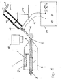
- Fig. 1 shows a first embodiment of a device for treating a crystal used in the invention. It is left in the Fig. 1 a holder 1 is shown, which serves to attach a protein crystal 2.
- the in the Fig. 1 shown bracket, which is referred to in its generic way as a "free mounting system" (freely mounted) is already known from the prior art and, for example, in the German patent DE 198 42 797 C1 been described. This document is in this respect fully incorporated in the disclosure of the present application.
- a freely assembled crystal is a crystal which is not in a liquid, as is customary, for example, according to the "soaking" known in the prior art.
- a holding capillary 5 attached to the free support end of the protein crystal 2 is held.
- the holding capillary preferably consists of a micropipette, in which one in the Fig. 1 not shown and connected to the other end of the micropipette pumping device, a negative pressure is generated, which serves to keep the protein crystal 2 at the free support end.
- the left end 8 of the insert part is formed so that the holder 1 can be attached to a goniometer head of an X-ray or synchrotron irradiation system.
- the diffraction of X-rays as they pass through the crystal lattice of the protein crystal can be exploited to deduce from the diffraction pattern the spatial arrangement of the atoms and molecules in the crystallized protein or to calculate the structure by mathematical operations.
- the required X-rays may be e.g. are generated by bombardment of copper or other materials with electrons (for example, CuK ⁇ radiation).
- the X-radiation may also be in a synchrotron, i. a particle accelerator, in which the X-ray radiation is emitted by electrons accelerated on circular paths.
- the synchrotron has a number of advantages over the conventional generation of X-radiation by electron bombardment of metals, despite the greater expenditure on equipment.
- the X-rays generated by synchrotrons have a higher intensity and can be selected in different wavelengths. In this way, it is also possible to use "white" X-ray light and thus bombard the crystal with X-ray flashes, which have X-rays of all wavelengths.
- the measurements with the synchrotron can be performed much faster than with conventional X-ray irradiation systems.
- a gas channel 6 is further integrated, the mouth end 7 is directed to the free support end of the holding capillary 5, to which the protein crystal 2 is attached.
- the attached at the end of the protein crystal 2 is completely enclosed by the gas stream from the gas channel 6, so that a defined gas atmosphere can be generated around the protein crystal around.
- the gas channel 6 is at its in the Fig. 1 connected as open end with a gas generating agent and a gas mixing agent, with which the composition of the gas stream can be variably adjusted. If that's about the protein crystal
- the gas mixture may serve, for example, to regulate the humidity to a predetermined optimum value.
- thermosetting means with which the temperature of the gas flow can be measured and adjusted to a specific predefinable value.
- Other gaseous substances can also be added to the gas stream, so that, for example, the nitrogen or oxygen content of the air can be modified, for example increased.
- the crystal is mounted a microscope with video system 10, with which the protein crystal can be observed during the treatment with the substance. Possibly.
- the treatment mode can be modified or the treatment adjusted.
- a device for treating a crystal with a substance as used in the invention further comprises a microdosing system 11, which is located on the right in FIG Fig. 1 is shown in section in a side view
- the microdosing system 11 comprises a so-called piezo pipette 12, which is held in a stand 15 and is aligned with the protein crystal 2 in such a way that it can be bombarded with drops by means of the piezo pipette.
- the piezo pipette is in the Fig. 1 for reasons of clarity on an enlarged scale in relation to the holder 1 shown.
- the piezo pipette is arranged so that the tip of the piezo pipette is at a distance of typically 3 mm from the protein crystal. Preferably, this distance is in a range of 1 - 5 mm, but can be selected larger or smaller under special circumstances.
- the piezo pipette 12 consists of a glass capillary 13, e.g. may consist of borosilicate glass.
- the diameter of the opening of the glass capillary is one of the factors influencing the size of the microdrops emitted from the piezo pipette, and may e.g. in a range between 5 and 50 microns.
- the glass capillary 13 is enclosed by a piezoelectric element 14 made of a material exhibiting a piezoelectric effect. to act a piezocrystal.
- the piezoelectric element 14 is also electrically connected via two cables 16 to a controller 17, with which a voltage can be applied to the piezoelectric element 14.
- a voltage pulse is applied by the control unit 17 to the piezoelectric element 14, the piezoelectric element 14 and with this also the glass capillary 13 is contracted and a drop is shot out of the opening of the piezo pipette.
- the control unit 17 differently shaped voltage pulses can be applied to the piezo pipette whose shapes affect the shape and size of the Mikto drops and their frequency the frequency of the micro-drops.
- a housing of a possible control device for controlling the piezo pipette is shown, wherein the individual control options based on the in the Fig. 2 illustrated switches and controls of the control unit to be explained.
- the controller initially has three different LCD displays 20, 21 and 22.
- the current value for the voltage level of the pulse output voltage for the piezo pipette control signal is displayed on the first LCD display 20. This value can be set variably via a rotary knob 23.
- the pulse width of the pipette drive signal which is displayed on the second LCD display 21 in microseconds, can be adjusted by means of a second rotary knob 24.
- a third knob 25 is provided to adjust the frequency of the voltage pulses applied to the piezo pipette, which is displayed on the third LCD display 22.
- This frequency which can be up to several kHz (eg 2 kHz), corresponds to the frequency with which the micro-drops are thrown out of the piezo pipette onto the crystal.
- the setting range of the frequency can be, for example, in a range between 1 Hz and 6 kHz.
- the height of the pulse output voltage and the width of the voltage pulses must first be set so that there is even a drop generation with the piezo pipette. Then the frequency chosen is that for the particular crystal treatment process ideal. The frequency can of course also be varied continuously during the crystal treatment process.
- the control unit also has two inputs 26 to which the two connection cables of the piezo pipette are connected. Furthermore, a power cable 27 and a network connection 28 are provided for the power supply of the control unit. Via the further signal input 29 predetermined voltage pulse sequences can be applied by other electrical devices in order to trigger the micro-droplet generation and to control the micro-droplet sequence and shape from the outside. This can e.g. be useful if there is a central control unit that controls both the drop generation and other parameters of crystal treatment such as the supplied via the crystal holder gas flow, the composition of the gas stream (eg its moisture content), the temperature of the gas stream, a connected X-ray system, etc. and synchronize the various control parameters in a predetermined manner.
- the switch 30 is provided to turn on and off the piezo pipette operation. Via the further switch 31 can be switched between single-voltage pulse operation and continuous voltage pulse operation, i. between single drop generation and continuous drop generation.
- a pushbutton 32 can also be provided, via which individual voltage pulses can be applied to the piezo pipette, if it is desired to shoot individual drops onto the crystal by hand.
- the switch 33 serves to be able to vary between different pulse shapes of the voltage pulses applied to the piezo pipette 12.
- a predetermined standard square-wave voltage pulse with predetermined duration and height can be generated
- a square-wave voltage pulse can be generated whose duration and height can be variably adjusted. It is of course also conceivable in other embodiments that voltage pulses are applied which deviate from the rectangular shape.
- the pulse shape of the voltage pulses is now chosen so that an optimal drop generation is ensured with respect to the crystal to be treated.
- Different sizes of microdrops e.g. can be suitable for different crystal sizes can be adjusted via the variation of the voltage pulse widths and voltage pulse heights that have the voltages applied to the piezo pipette.
- the glass capillary 13 of the piezo pipette 12 is typically via a supply line 18 with a in the FIG. 1 Not shown storage vessel connected containing the solution to be dropped onto the protein crystal.
- This solution contains the substance or substances with which the protein crystal is to be treated.
- the upper edge of the liquid level of the liquid in the storage vessel should be set slightly higher than the lower edge of the pipette nozzle.
- the liquid can also be sucked directly into the piezo pipette via the outlet opening of the piezo pipette, in order to be able to deliver it again later.
- a tempering device may also be arranged around the storage vessel in order to bring the liquid in the storage vessel to a desired temperature.
- the pH and / or ionic strength (or specific salt concentrations) of the solution may be adjusted to a desired value according to methods known in the art.
- microdrops are to be understood as meaning droplets whose volume is less than 1 ⁇ l, the volume of the microdrops preferably being between 1 ⁇ l (nanoliters) and 1 ⁇ l (picocolers), more preferably between 100 ⁇ l and 20 pl and even more preferably between 20 pl and 4 pl. From these quantities, it is possible to calculate the appropriate diameter of the drops by the volume formula, assuming approximately that the drops are spherical. The desired droplet size can be adjusted according to the invention.
- micro-drops of the liquid to be applied to the crystal are preferably smaller than the volume of the crystal.
- a typical crystal volume can be, for example, in a large diameter of 1 nl.
- the volume of the micro-drops used in the specific case is chosen as a function of the volume of the crystal.
- the volumes of the microdroplets are less than 50%, e.g. 1 to 20% of the crystal volume and preferably 1, more preferably 5 to 10% of the crystal volume.
- Drop generation by means of a piezo pipette is only one example of a microdosing device. Other devices that are capable of producing microdrops may also be used in the invention.
- the liquid is forced under pressure from a storage vessel to the microvalve, which is opened by a control unit electrically within a short time interval and then closed again to the drops to create.
- a control unit electrically within a short time interval and then closed again to the drops to create.
- the limitation of the droplet size results here by the still controllable opening duration of the valve.
- a nebulizer can also serve as a microdosing system.
- an atomizer has the disadvantage over the solutions described above that the alignment of the drops on the crystal is more difficult. Therefore, it is advantageous for the atomizer to be followed by a means which ensures the orientation of the microdrops obtained from the atomizer onto the crystal.
- the microdosing device consists of a "loop", for example.
- a loop with the individual drops (or only a drop) on the crystal by, for example. Shake or dripping from the "loop".
- the applied drop volumes are small enough for the protein crystals (in the sense of the above-disclosed volume ratios of crystal to drop).
- a perforated plate which, for example, rotates at a certain frequency, can be arranged between the droplet generation apparatus and the crystal used in the invention. Since, depending on the device for generating droplets, the provision of small microdroplets often requires a higher droplet frequency, it is possible to pass only two, three or four or fewer drops onto the crystal via the intermediary of a perforated plate. Also, the volume applied to the crystal can be controlled.
- a protein crystal is first attached to the free end of the support capillary 2.
- a so-called "loop" that is to say a type of loop in which the protein crystal is attached.
- the protein crystal is free of any surface solution and thus accessible for solutions that can be applied directly from outside by means of the microdosing.
- a gas atmosphere is now generated around the protein crystal 2 by passing a gas stream of defined composition and temperature through the gas channel 6 of the holder 1.
- the method described will typically be an air stream, optionally with the admixture of other gaseous substances, with a controlled moisture content (i.e., water content) and a controlled temperature.
- This process of setting the optimum humidity or the optimal Auftropffrequenz by the microdosing can be controlled automatically via a control element that makes appropriate changes in the humidity of the air flow and / or Auftropffrequenz when the measured volume of the crystal changes.
- the aim is to keep the volume of the crystal as constant as possible, ie, the volume is typically not more than 40%, preferably not more than 20%, particularly preferably not more than 10% of the starting volume.
- the volume change can be measured via a surface projection.
- the crystal may also be irradiated with pulsed light, e.g. via a stroboscope in order to be able to measure the volume of the drop at regular intervals by means of the video system.
- pulsed light e.g. via a stroboscope
- the process according to the invention is also particularly advantageous if ligands, for example inhibitors or other substances, are to be introduced into a crystal, which are difficult to dissolve even in an aqueous solution.
- ligands for example inhibitors or other substances
- a number of ligands proves to be extremely difficult to dissolve in aqueous systems, so that these ligands / inhibitors are not introduced into the crystal with the classic "soaking" process described in the introduction to the description can be, since the concentration of ligands / inhibitors in the aqueous solution is too low.
- aqueous solution in which these ligands and / or inhibitors are dissolved is then dropped onto the crystal by means of the microdosing system, the water evaporates completely after each dripping, while the ligand remains on or in the crystal. Repeated dropping cycles allow larger amounts of the (poorly soluble) ligand to be applied to the crystal.
- the ligand accumulates gradually on or in the crystal until a sufficient amount of ligand is incorporated into the crystal and sufficient ligand-protein complex formation (ie, occupancy of the crystal at the binding sites of the crystallized proteins is sufficient, an electron density for the ligand) Reached ligands to determine) is reached.
- the advantage of this method is also that the protein crystals do not need to be mixed with a further solvent and thus the treatment of sensitive crystals is gentler. In addition, there is no danger that the ligand precipitates on the crystal or in the solvent channels due to its low solubility.
- the amount of solution to be dropped by the microdosing system can be calculated by the concentration of the solution as well as an estimate of the protein's molarity in the crystal.
- Another advantage of the method is that with water as the only solvent for the ligand compared to other solvents or liquids can achieve particularly small droplet sizes, which is particularly important for small protein crystals, since according to the invention, the droplet size is smaller than the size of the crystal should be.
- the apparatus for treating a crystal having a substrate used in the invention may also be integrated into an X-ray irradiation apparatus or synchrotron irradiation apparatus, so that it becomes possible to take diffraction images of the crystal during treatment of the protein crystal with the substance and thus the treatment process, ie successive occupation the binding sites of the crystal, "online" to watch.
- the holder 1 can be attached, for example, to a goniometer of an X-ray or Synchtotron irradiation system.
- the protein crystal can also be frozen before X-ray crystallographic examination, which is usually done using liquid nitrogen (so-called cryo-crystallography).
- the electron density of the structure can be determined.
- the device may e.g. also be combined with an absorption spectrum acquisition system to acquire the absorption spectrum of the crystal.
- a solubilizer can also or only be added to the gas stream guided through the holder 1, which solubilizer is suitable for the substance to be introduced into the protein crystal, ie for example a solubilizer for a sparingly soluble ligand.
- an evaporator may additionally be provided in order to evaporate the solubilizer prior to introduction into the gas channel 9 of the holder 1.
- a device may be provided which serves to adjust the concentration of the solubilizer in the gas stream variable and adjust the required conditions.
- the ligand solution can then be applied to the protein crystal in microdrop form via the piezo pipette.
- solubilizers or only the gas stream supplied to the ligand solution can also be combined so that the solvent mediator (identical or different) is added both in the microdroplet and in the gas stream.
- solvent mediator identical or different
- such a method according to the invention is associated with less expenditure of time in comparison to previous "soaking” processes, since fewer attempts have to be made to successfully complete the crystal treatment because of the gentler crystal treatment.
- the method according to the invention is not only suitable for introducing ligands into protein crystals. It is also possible to carry out a number of other treatment methods with other solutions of protein crystals in the manner according to the invention.
- the solution applied via the micro-drops by means of the micro-dosing system may contain several different substances with which the crystal is to be treated. It may be, for example, several ligands, for example w. multiple substrates or a substrate and a catalytically acting ligand, which are dissolved in a solution to be applied by means of a piezo pipette on the crystal.
- the piezo pipette can also be provided with a special liquid supply system, with which it is possible to control the supply of different liquids in the piezo pipette in time in the desired manner.
- a fluid delivery system represents. That in the Fig. 3
- the liquid supply system shown comprises a precision syringe 40 consisting of a cylinder 41 in which one via a (in the Fig. 3 not shown) motor driven piston 42 can reciprocate.
- various fluids may be drawn from the fluid reservoirs 43, 44, 45, or 46 into the cylinder when one of the corresponding electrically controllable valves 47, 48, 49, 50 is opened, and additionally before the cylinder lying electrically controllable valve 51 is opened. If the valve 51 is then closed again, the electrically controllable valve 52 located at the outlet of the cylinder is opened and the piston 42 is driven upwards, the aspirated liquid can be stirred via the liquid piping 53 leading to the piezo pipette to the piezo pipette, and finally finally in the form of drops to be given the crystal.
- the containers 45 and 46 may contain two different solutions of different ligands to complex with the protein of the crystal to be dripped.
- the treatment of the crystal can be done, for example, so that first the solution 1 from the container 45 and then the solution 2 is dropped from the container 46 onto the crystal. Between the two solutions, a cleaning solution can be flushed through the lines, which is located in the container 44.
- the further container 47 serves as a waste container, to absorb fluid quantities that are no longer needed and must be removed from the delivery system. By suitable timing of the valves 47 - 52 and the piston 42, the piezo pipette can now be supplied to the desired solutions in the desired amount.
- a further example for the application of a method according to the invention is the so-called "back soaking", in which certain substances already bound to the crystal structure of the protein are exchanged by other substances, ie a cocrystal is "gesoakt" again with the aim of a substitution.
- a ligand can be replaced by another ligand, which is in the solution which is applied to the protein crystal via microdrops.
- the method according to the invention can also be used in a very gentle manner to apply so-called "cryopuffers" to a protein crystal (complexed or uncomplexed).
- Many protein crystals must be frozen prior to X-ray crystallographic examination for stability reasons, which, as described above, is usually performed using liquid nitrogen.
- the cryo-buffers are used during the freezing process to prevent the formation of ice that would destroy the protein crystal. Examples of cryogenic buffers are glycerol or 2-methyl-2,4-pentanediol (MPD).
- MPD 2-methyl-2,4-pentanediol
- the cryo-buffers can be filled into the reservoir of the piezo pipette and then sprayed onto the protein crystal in a manner similar to the ligand solution with the microdosing device.
- a plurality of microdosing systems eg a plurality of piezo pipettes, with which different or identical substances (for example at two different, locally delimited regions of the crystal) are applied to the crystal.
- Such an arrangement may be advantageous, for example, if two different ligands are to be introduced into a protein crystal structure. The ligands are then dissolved in various solutions which are added to the two liquid reservoirs of two piezo pipettes. Using the two piezo pipettes, the two solutions with the various ligands are then applied in microdrop form to the protein crystal.
- cryo-soaking can be carried out with the inventive method in a particularly advantageous manner.
- “Cryo-soaking” is characterized by the combination of ligand addition and simultaneous freezing of a protein crystal.
- a microdosing system e.g. the cryo-buffer described above and, via the other microdosing system, a solution in microdrop form onto the protein crystal which contains the ligand to be introduced into the protein crystal.
- Another application would be to spray reactants that react in a certain way with the protein crystal.
- the guided through the support for the crystal gas stream certain substances are added, with which the crystal is to be treated. So, for example, in soaking a ligand to be introduced into the protein crystal structure is added to the gas stream while solvent for this ligand is dropped by means of the microdosing system or a solution is dissolved in which a further ligand is dissolved, which are incorporated into the crystal structure of the protein crystal simultaneously with the ligand supplied via the gas stream should.
- the solvent for the ligand can also be supplied to the crystal via the gas stream.
- an evaporator can be used to previously convert the solvent into the gas phase.
- a ligand to be supplied via the gas stream can be supplied to the gas stream via the evaporator.
- solvent with ligand can be supplied to the protein crystal via the gas stream, for example, while a cryopuffer is dropped onto the microcrystal via the microdosing system.
- the inventive method are suitable, wherein a crystal, such as.
- a crystal such as.
- a potential ligand is applied to the crystal by a method of the invention,
- diffraction intensities are measured at a time interval of variable length, at least one image, preferably 2 to 10 images, being taken at each time and
- comparing these temporally spaced diffraction intensities which typically reflect different accumulation states of the potential ligand on the crystal, in their temporal sequence. It is particularly preferred if the crystal remains in an orientation during all diffraction recordings.
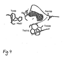
- FIG. 5 is a diagrammatic representation of FIG. 5
- the cleavage product Pro-Ile of the inhibitor diprotin A and individual amino acids in the vicinity of the active site of the DPIV around Ser630 are shown as a stick model. Oxygen atoms are red, nitrogen atoms blue and carbon atoms gray.
- the inhibitor and Ser630, which is covalently coupled to the inhibitor, are additionally superimposed by its 2F o -F c electron density (contoured at 1 ⁇ ). The inhibitor is clearly defined in its electron density ( FIG. 5 ).
- the tripeptide used with the sequence Ile-Pro-Ile cleaves the C-terminal isoleucine, while the dipeptide is covalently linked to Ser630 and is not cleaved. In that sense, diprotin A behaves more like a suicide substrate rather than an inhibitor.
- a process is also subject matter of the present patent application, in which the treatment according to the invention of a free-assembled crystal with a device for generating microdrops is carried out in batch mode in order to be able to work with a high throughput of crystals to be complexed.
- the crystal or crystals preferably mounted freely, is initially held. This provision of the crystals until the next process step (b) can be carried out, for example, by storage of the crystals in the frozen state or, more preferably, in a sealed vessel (eg vials) in the vapor equilibrium with the crystallization liquid to the integrity of the crystal or the Ensure crystals to process step (b).
- microdroplets of, for example, a ligand-containing solution are applied to the freely assembled crystals, as disclosed in accordance with the invention, in order to complex the crystal, for example, with a ligand.
- the crystals treated according to the invention must be stored in a process step (c) before the X-ray crystallographic examination can be carried out in process step (d).
- the storage in process step (c) is typically carried out in the frozen state, preferably in liquid nitrogen.
- the carrying out of method steps (a) or (c) can be carried out, for example, in sample changers, as used in cryocrystallography, so-called "autosampler".
- the samples are arranged on a sample carrier and this is moved horizontally in order to record samples in batch mode by a sample receiving device can.
- the control is automatic.
- a device for freezing is provided.
- a thrombin crystal was mounted at the previously determined starting moisture of 93% with a "loop" on the Free Mounting System. Excess reservoir buffer was out carefully remove the "loop” under the microscope with a strip of filter paper. The stability of the size of the crystal was controlled by the video system.
- the piezo pipette was filled with a 100 mM solution of PMSF, a ligand (inhibitor) of thrombin, in isopropanol.
- a highly concentrated PMSF solution in an organic solvent was used.
- the crystal Upon completion of the dropping, the crystal was wetted with PFPE oil (perfluoropolyether) and flash frozen in liquid nitrogen.
- PFPE oil perfluoropolyether
- the X-ray crystallographic data set was recorded on a rotating copper anode.
- the processing of the data was carried out with the programs XDS and XSCALE, refinement and manual model making were carried out with the programs CNX and O.
- the statistics of data collection, processing and refinement are given in Table 2. Despite the dripping of the pure solvent did not affect the diffraction quality of the crystal, as can be seen in particular from the value of R meas .
- FIG. 4 A graphical representation of the results of X-ray crystallographic examination is FIG. 4 refer to.
- the crystals of the DPIV show in the native state only a very limited scattering behavior. Only through moisture optimization with the "Free Mounting System” can the achievable dissolution of the crystals be decisively improved. In the optimized state with reduced humidity, the crystals are also characterized by increased stability and are therefore better suited for "soaking" experiments by dripping.
- the ligand used was an inhibitor solution of aqueous diprotin A solution (50 mM).
- aqueous diprotin A solution 50 mM.
- the inhibitor used was Pefabloc SC (4- (2-aminoethyl) benzenesulfonyl fluoride hydrochloride, K i : 6.5 ⁇ M), which is characterized by high stability in the aqueous system.
- a concentration of thrombin in the crystal was about 9.75 pmol / 300 pl or 32.5 mM. Since the aim was to apply the inhibitor in the stoichiometric ratio of 2: 1 in order to achieve the highest possible occupation, the amount of inhibitor required was 19.5 pmol (9.75 pmol x 2).
- the amount of inhibitor solution to be dripped depends on the concentration of the inhibitor and was chosen experimentally for three concentrations under the assumption of a droplet size of 10 pl as achievable with the use of water, as shown in Table 5.
- 1 drop per sec could be applied regularly to the crystal.
- the frequency was significantly increased when at reduced moisture in the sheath stream, which leads to a drying out of the crystals, the loss of moisture compensated by a faster dripping and thus the rel. Moisture had to be kept constant at the crystal. This allowed a frequency of 20 drops per second.
- the times resulting therefrom at different inhibitor concentrations are also shown in Table 5.
Abstract
Description
Die vorliegende Erfindung bezieht sich auf ein Verfahren zum Behandeln eines Kristalls mit einer Flüssigkeit und insbesondere auf ein Verfahren zum Einbringen von Liganden und/oder Inhibitoren in eine Proteinkristallstruktur.The present invention relates to a method for treating a crystal with a liquid, and more particularly to a method for introducing ligands and / or inhibitors into a protein crystal structure.
In der Proteinkristallographie kommt es häufig vor, daß vor der kristallographischen Messung Liganden oder Inhibitoren in eine Proteinstruktur bzw. einen Proteinkristall eingebracht werden sollen. Ziel ist es dabei, die kristallographische Struktur eines Proteins ohne und mit Ligand oder Inhibitor zu vergleichen und die räumliche Anordnung des Liganden oder Proteins zu ermitteln. Liganden können hierbei alle an eine Protein oder Polypeptid bindenden Moleküle oder Substanzen sein, die bspw. inhibitorische Wirkung oder auch agonistische Wirkung auf die Funktion des Proteins haben können. Ggf. können Liganden organisch-chemische Moleküle sein oder auch (modifizierte) Antikörper oder Antikörperfragmente, native Bindungspartner oder Fragmente, ggf. modifiziert, vom kristallisierten Protein. Weiterhin werden regelmäßig auch Schwermetallatom-Derivate in der Kristallographie benötigt, um die entsprechende Phaseninformationen zu erhalten. Ein Ligand i.S. der vorliegenden Erfindung kann daher auch ein an das kristallisierte Protein bindendes Schwermetallatom(salz)In protein crystallography it often happens that ligands or inhibitors are to be introduced into a protein structure or a protein crystal before the crystallographic measurement. The aim is to compare the crystallographic structure of a protein without and with ligand or inhibitor and to determine the spatial arrangement of the ligand or protein. Ligands may in this case be any molecules or substances which bind to a protein or polypeptide and which may, for example, have an inhibitory effect or also an agonistic effect on the function of the protein. Possibly. For example, ligands may be organic chemical molecules or also (modified) antibodies or antibody fragments, native binding partners or fragments, optionally modified, from the crystallized protein. Furthermore, heavy metal atom derivatives in crystallography are also required on a regular basis in order to obtain the corresponding phase information. A ligand in the sense of the present invention can therefore also contain a heavy metal atom (salt) which binds to the crystallized protein.
Ein im Stand der Technik bekanntes Verfahren zum Einbringen von Liganden, bspw. Inhibitoren, ist das sogenannte "Soaking" mit einem Puffer, der aus der Kristallisationslösung sowie dem Liganden besteht. Falls ein in den Kristall zu "soakender" Ligand schlecht oder nur schwerlöslich sind, können dem Puffer zur Erhöhung der Löslichkeit desselben weitere Substanzen als Löslichkeitsverbesserer zugesetzt werden. Beispielsweise kann es sich um Lösungsmittel wie DMSO (Dimethylsulfoxid), TFE, Ethanol, 2-Nitropropan oder andere organische Lösungsmittel, insbesondere chlorierte Lösungsmittel, ggf. auch Emulgatoren handeln.One known in the prior art method for introducing ligands, for example. Inhibitors, is the so-called "soaking" with a buffer consisting of the crystallization solution and the ligand. If a ligand to be "soaked" in the crystal is poorly or sparingly soluble, further substances may be added to the buffer to increase its solubility as a solubility improver. For example, it may be solvents such as DMSO (dimethyl sulfoxide), TFE, ethanol, 2-nitropropane or other organic solvents, in particular chlorinated solvents, optionally also emulsifiers.
Das "Soaking"-Verfahren besitzt verschiedene Nachteile. So besteht ein Nachteil darin, daß die Kristalle beim "Soaking" einer anderen Umgebung ausgesetzt werden müssen, wodurch der Kristall Schaden erleiden kann, d.h. insbesondere, dass die Mikrostruktur des Kristalls nach dem "Soaking" Unregelmäßigkeiten aufweist, die das Diffraktionsvermögen des Kristalls beeinträchtigen. Sollen z.B. schwerlösliche Inhibitoren oder Liganden in die Proteinkristallstruktur eingebracht werden, so benötigt man sehr hohe Konzentrationen an Lösungsmittel. Gerade hohe Lösungsmittelkonzentrationen führen aber häufig zur Zerstörung der fragilen Proteinkristalle, wie zuvor erwähnt.The soaking process has several disadvantages. Thus, there is a disadvantage in that the crystals must be exposed to a different environment during "soaking", which can cause damage to the crystal, i. in particular, that the microstructure of the crystal after soaking has irregularities that affect the diffraction power of the crystal. If, for example, poorly soluble inhibitors or ligands are introduced into the protein crystal structure, so you need very high concentrations of solvent. However, especially high solvent concentrations often lead to the destruction of the fragile protein crystals, as mentioned above.
Der Artikel "
Der Artikel "
- Befestigen der hochkristallinen beta-chitin Probe mittels Klebstoff an einer Glasspitze, die ihrerseits an einem Standard Probenhalter (Hampton Research) angebracht wird,
- Trocknen der Probe für einige Stunden in einem Vakuumofen bei 50°C,
- Transfer der Probe zum Mikrogoniometer der European Synchrontron Radiation Facility und Ausrichten der Probe am Mikrogoniometer,
- direktes Aufbringen von Mikrotropfen von destilliertem Wasser auf die Probe.
- Affix the highly crystalline beta-chitin sample to a glass tip by adhesive, which in turn is attached to a standard sample holder (Hampton Research),
- Drying the sample for several hours in a vacuum oven at 50 ° C,
- Transfer of the sample to the microgoniometer of the European Synchrontron Radiation Facility and alignment of the sample on the microgoniometer,
- direct application of microdrops of distilled water to the sample.
Der Artikel "
Darüber hinaus besteht ein weiterer Nachteil des herkömmlichen "Soaking"-Verfahrens in dem hohen Zeitaufwand des Verfahrens. Dieser ist zum einen durch die unter Umständen zahlreichen (repetitiven) "Soaking"-Prozesse bedingt, die, ggf. unter Veränderung der Konzentrationsverhältnisse des zu "soakenden" Liganden durchlaufen werden müssen, um überhaupt eine geeignete, die Liganden oder Inhibitoren enthaltende, also komplexierte Proteinkristallstruktur (Cokristall) zu erhalten, und zum anderen dadurch, daß bereits ein einzelner Soaking-Prozeß bereits sehr zeitaufwendig sein kann, da bspw. die Diffusionskinetik beachtet werden muß.Moreover, another disadvantage of the conventional "soaking" method is the high time spent on the process. On the one hand, this is due to the possibly (repetitive) "soaking" processes which, if necessary, must be carried out with a change in the concentration ratios of the ligands to be "soaked" in order to provide any suitable, ie complexed, ligands or inhibitors On the other hand, that already a single soaking process can be very time-consuming, since, for example, the diffusion kinetics must be taken into account.
Ein weiterer Nachteil des "Soaking"-Verfahrens besteht darin, daß röntgenkristallographische Untersuchungen oder Untersuchungen des Proteinkristalls mit Synchrotronstrahlung während des "Soaking"-Verfahrens technisch nicht möglich sind.Another disadvantage of the "soaking" method is that X-ray crystallographic examinations or investigations of the protein crystal with synchrotron radiation during the "soaking" process are not technically possible.
Die Aufgabe der Erfindung besteht nun darin, ein Verfahren zur Behandlung eines Kristalls mit einer Substanz zu schaffen, die im Vergleich zu bisherigen Verfahren unter anderem eine schonendere Behandlung von Kristallen und insbesondere Proteinkristallen und die einfachere und/oder effizientere Herstellung von komplexierten Kristallen und insbesondere Proteinkristallen sowie die einfache Herstellung von bisher nur schwer oder überhaupt nicht herstellbaren komplexierten Kristallen und insbesondere Proteinkristallen erlauben.The object of the invention is therefore to provide a method for treating a crystal with a substance which, in comparison to previous methods, inter alia a gentler treatment of crystals and in particular protein crystals and the simpler and / or more efficient production of complexed crystals and in particular protein crystals as well as the simple production of previously difficult or impossible to produce complexed crystals and in particular protein crystals allow.
Diese Aufgabe wird durch ein Verfahren zum Behandeln eines Kristalls mit einer Flüssigkeit unter Verwendung einer Vorrichtung mit einer Halterung zur Befestigung des Kristalls und einem Mikrodosiersystem gelöst, das im Verhältnis zur Halterung so angeordnet ist, daß damit Mikro-Tropfen einer Flüssigkeit, die bspw. Lösungsmittel und mindestens einen Ligandentyp aufweist, auf den in der Halterung befestigten Kristall aufgebracht werden können.This object is achieved by a method of treating a crystal with a liquid using a device with a support for attaching the crystal and a microdosing system which is arranged in relation to the holder such that it microdrops a liquid, for example. Solvent and at least one type of ligand can be applied to the crystal mounted in the holder.
Durch das Auftropfen von Mikro-Tropfen mit der Vorrichtung läßt sich eine wesentlich schonendere Behandlung von Kristallen und insbesondere Proteinkristallen mit bestimmten aufzubringenden Substanzen, die in einer Lösung enthalten sind, erreichen. Diese Substanzen können bei Proteinkristallen Liganden, bspw. Inhibitoren, Substrate oder Reaktanden, sein. Bei den Liganden wird es sich bei Proteinkristallen typischerweise um Agonisten, Substrate oder Antagonisten der kristallisierten Proteine handeln. Weiterhin wird ein System zur Verfügung gestellt, das es erlaubt, einen Kristall, insbesondere einen Proteinkristall, unabhängig von der Umgebung in einer Mutterlösung, wie in allen Experimenten nach dem Stand der Technik mit einem Liganden zu komplexieren. Auf diese erfindungsgemäße Weise können Proteinkristalle auch in solchen Fällen, die mit den Verfahren nach dem Stand der Technik nicht mit Liganden komplexierbar sind, dennoch eine Komplexbildung eingehen. Die Ursache für die Überlegenheit des erfindungsgemäßen Verfahrens, das einen frei montierten Kristall und die Bereitstellung eines Mikro(Piko)tropfens durch Verwendung einer entsprechenden Vorrichtung voraussetzt, ist die Verschiebung des Gleichgewichts der Reaktion zwischen Ligand und kristallisiertem Protein zum komplexierten Protein. Dies wiederum hängt mit der Reduktion der apparenten Dissoziationskonstante KD zusammen, da die Konzentration der freien Komponenten durch die Isolation der Proteinkristalls von der den Kristall (nach dem Stand der Technik) umgebenden Mutterlauge erheblich eingeschränkt ist. Diese Reduktion der KD erlaubt es auch dann Komplexe zu erhalten, wenn die Bindungskonstante des Liganden an das kristallisierte Protein eigentlich gering ist oder der Ligand nur schwach löslich ist und daher Verfahren nach dem Stand der Technik (Kristall in Mutterlösung) keine oder nur eine geringfügige Komplexierung (die für röntgenkristallographische Folgeexperimente nicht ausreichend ist) ergeben.By the dripping of micro-drops with the device can be a much gentler treatment of crystals and in particular protein crystals with certain applied substances that are contained in a solution reach. These substances may be ligands for protein crystals, for example inhibitors, substrates or reactants. The ligands will typically be protein crystals of agonists, substrates or antagonists of the crystallized proteins. Furthermore, a system is provided which allows a crystal, in particular a protein crystal, to be complexed independently of the environment in a mother solution, as in all prior art experiments with a ligand. In this way, protein crystals can even in such cases, which are not complexable with the methods of the prior art with ligands, nonetheless complexing. The cause of the superiority of the process of the invention, which requires a freely assembled crystal and the provision of a micro (pico) drop by use of a corresponding device, is the shift of the equilibrium of the reaction between ligand and crystallized protein to the complexed protein. This, in turn, is related to the reduction of the apparent dissociation constant K D , since the concentration of the free components by the isolation of the protein crystal from the mother liquor surrounding the crystal (according to the prior art) considerably is restricted. This reduction in K D allows complexes to be obtained even if the binding constant of the ligand to the crystallized protein is actually low or the ligand is only slightly soluble, and therefore no or only a small amount of prior art processes (crystal in mother solution) Complexation (which is not sufficient for X-ray crystallographic follow-up experiments).
Darüber hinaus ist es von erheblicher Bedeutung, bei der Komplexbildung nicht nur die erfindungsgemäß vorteilhafte Verschiebung des Gleichgewichts der Komplexierungsreaktion zu betrachten, sondern auch die durch das System mit frei montiertem Kristall vorteilhafte Kinetik der Komplexbildung, insbesondere bei schwach löslichen Liganden. Der erfindungsgemäß frei montierte Kristall (ohne die Umgebung einer Mutterlösung) hat eine größere Stabilität als der in der Mutterlösung nach dem Stand der Technik "gesoakte" Proteinkristall. Diese größere Stabilität kann genutzt werden, um bspw. die Komplexierung des Liganden, mit dem besonders bevorzugten Ziel mindestens 90%iger, vorzugsweise mindestens 95%iger Absättigung der im Kristall für den Liganden enthaltenen Bindungsplätze, durch die Verwendung von Verfahren zu erzwingen, denen ein Proteinkristall im Falle des "Soakings" oder der Kokristallisation nach dem Stand der Technik nicht zugänglich wären. Insbesondere vorteilhaft in diesem kinetischen Zusammenhang ist die Verwendung von auf Temperaturen oberhalb von 20°C erwärmter Ligandenlösung, die als Pikotropfen auf den frei montierten Kristall aufgetragen wird. Diese Erwärmung kann bspw. mindestens 30°C, vorzugsweise mindestens 40°C, noch stärker bevorzugt mindestens 50°C betragen. Auch eine Erwärmung bis zu 75°C ist möglich. Darüber hinaus oder in Kombination mit der Erwärmung der Ligandenlösung kann diese auf den Kristall, bspw. direkt aufgespritzte, als Pikotropfen aufgetragene Ligandenlösung auch organische Lösungsmittel enthalten oder aus diesen bestehen. Sofern das organische Lösungsmittel mit Wasser löslich ist (bspw. DMSO oder TFE) kann dieses zu mindestens 20 Vol-%, vorzugsweise zu mindestens 40 Vol.-% und noch stärker bevorzugt zu mindestens 50 Vol.-% in einem Wasser/organisches Lösungsmittel-Gemisch enthalten sein. Auch kann der Ligand in einem reinen organischen Lösungsmittel oder in einem Gemisch verschiedener organischer Lösungsmittel gelöst und als Mikrottopfen auf den frei montierten Kristall (sie hierzu im folgenden) aufgetragen werden. Der Einsatz organischer Lösungsmittel, der wiederum nur durch die erfindungsgemäße Verwendung eines frei montierten Kristalls und eines Mikrotropfens möglich wird, ist insbesondere dann bevorzugt, wenn die Liganden in wässriger Lösung nur schwer oder unlöslich sind. Schließlich kann der frei montierte Kristall auch einem Verdampferstrom ausgesetzt sein, wobei über einen Verdampfer organisches Lösungsmittel oder ein organische Lösungsmittelgemisch verdampft wird. Auf diese Weise wird das organische Lösungsmittel, bspw. DMSO oder Chlorkohlenwasserstoff, auf/im Kristall angereichert und dadurch die Löslichkeit des in Wasser schwer löslichen Liganden erhöht.In addition, it is of considerable importance to consider not only the shift of the equilibrium of the complexation reaction which is advantageous according to the invention, but also the kinetics of the complex formation advantageous by the system with freely assembled crystal, in particular in the case of weakly soluble ligands. The present invention freely mounted crystal (without the environment of a mother solution) has a greater stability than the "gesoakte" in the mother liquor according to the prior art protein crystal. This greater stability can be used, for example, to force the complexing of the ligand, with the particularly preferred goal of at least 90%, preferably at least 95%, saturation of the binding sites contained in the crystal for the ligand, by the use of methods Protein crystal in the case of "soaking" or cocrystallization according to the prior art would not be accessible. Particularly advantageous in this kinetic context is the use of heated to temperatures above 20 ° C ligand solution, which is applied as a picotype on the free assembled crystal. This heating may, for example, be at least 30 ° C., preferably at least 40 ° C., even more preferably at least 50 ° C. Also, heating up to 75 ° C is possible. In addition, or in combination with the heating of the ligand solution, this may also contain or consist of organic solvents on the crystal, for example directly sprayed on, applied as a picotrope ligand solution. If the organic solvent is soluble with water (eg DMSO or TFE), it may contain at least 20% by volume, preferably at least 40% by volume and even more preferably at least 50% by volume in a water / organic solvent. Mixture be included. Also, the ligand may be dissolved in a pure organic solvent or in a mixture of various organic solvents and applied as a microtube to the free assembled crystal (see below). The use of organic solvents, which in turn is made possible only by the use according to the invention of a freely assembled crystal and a microdrop, is particularly preferred when the ligands are difficult or insoluble in aqueous solution. Finally, the free-assembled crystal can also be exposed to an evaporator stream, wherein an organic solvent or an organic solvent mixture is evaporated via an evaporator. In this way, the organic solvent, for example. DMSO or chlorinated hydrocarbon, enriched on / in the crystal and thereby increases the solubility of the poorly water-soluble ligand.
Gemäß einer Ausgestaltung ist in der in der Erfindung verwendeten Vorrichtung zum Behandeln eines Kristalls mit mindestens einer Substanz die Kristallhalterung so ausgebildet, daß durch die Halterung ein Gasstrom geführt werden kann, der auf den in der Halterung befestigten Kristall gerichtet ist. Dadurch kann der Kristall während der Behandlung durch die Mikro-Tropfen in einer definierten Umgebung gehalten werden.According to one embodiment, in the apparatus for treating a crystal having at least one substance used in the invention, the crystal holder is formed so that a gas flow directed toward the crystal fixed in the holder can be guided by the holder. This allows the crystal to be kept in a defined environment during treatment by the microdrops.
Falls es sich bei dem Kristall um einen Proteinkristall handelt und die Substanz in der aufzutropfenden Flüssigkeit aus gelösten Liganden, bspw. Inhibitoren, besteht, die in die Kristallstruktur des Proteinkristalls eingebracht werden sollen, so kann dem Gasstrom auch gemäß einer weiteren vorteilhaften Ausführungsform ein Lösungsvermittler (s. obige Ausführungen) beigemischt werden, der insbesondere bei schwerlöslichen Liganden die Diffusion durch den Proteinkristall bzw. die Bindung an die kristallisierten Proteine wesentlich erleichtern kann.If the crystal is a protein crystal and the substance in the liquid to be dripped consists of dissolved ligands, for example inhibitors, which are to be introduced into the crystal structure of the protein crystal, then according to a further advantageous embodiment, a solubilizer ( see above), which in particular in the case of poorly soluble ligands can substantially facilitate the diffusion through the protein crystal or the binding to the crystallized proteins.
Es ist ferner besonders vorteilhaft, daß die in der Erfindung verwendete Vorrichtung auch auf einem Goniometerkopf im Röntgenstrahl oder in einem Synchrotron befestigt werden kann, so daß der zeitliche Ablauf der Veränderung der kristallisierten Proteinstruktur, z.B. infolge der Ligandenbindung während des Auftropfens der Mikro-Tropfen, im Meßgerät beobachtet werden kann.It is also particularly advantageous that the device used in the invention can also be mounted on a goniometer head in X-ray or in a synchrotron, so that the timing of the change of the crystallized protein structure, e.g. due to ligand binding during microdrop dropping, can be observed in the meter.
Die Aufgabe der Erfindung wird durch ein Verfahren zum Behandeln eines Kristalls entsprechend Anspruch 1 gelöst.The object of the invention is achieved by a method for treating a crystal according to
Weitere vorteilhafte Ausführungen des erfindungsgemäßen Verfahrens ergeben sich aus den abhängigen Ansprüchen.Further advantageous embodiments of the method according to the invention will become apparent from the dependent claims.
Bevorzugte Ausführungsformen der vorliegenden Erfindung werden nachfolgend unter Bezug auf die beiliegende Zeichnung näher erläutert. Es zeigen
-
Fig. 1 eine teilweise im Schnitt dargestellte Ansicht einer Ausführungsform einer in der Erfindung verwendeten Vorrichtung zum Behandeln eines Kristalls mit einer Lösung, -
Fig. 2 ein Gehäuse eines Steuergeräts zur Steuerung eines bei einer Ausführungsform der in der Erfindung verwendeten Vorrichtung verwendeten Mikrodosiersystems, -
Fig. 3 zeigt ein Flüssigkeitszufuhrsystem für ein Mikrodosiersystem, das bei einer Ausführungsform der in der Erfindung verwendeten Vorrichtung verwendet werden kann.
-
Fig. 1 FIG. 4 is a partially sectioned view of an embodiment of an apparatus for treating a crystal with a solution used in the invention; FIG. -
Fig. 2 a housing of a control device for controlling a micro-dosing system used in one embodiment of the device used in the invention, -
Fig. 3 shows a fluid delivery system for a microdosing system that can be used in one embodiment of the device used in the invention.
Die Erfindung wird im folgenden am Beispiel der Behandlung von Proteinkristallen beschrieben, sie kann aber auch in analoger Weise bei der Behandlung von anderen Kristallen eingesetzt werden.The invention will be described below using the example of the treatment of protein crystals, but it can also be used in an analogous manner in the treatment of other crystals.
Die Halterung 1, die in der
In einer Röntgen- oder Synchrotronbestrahlungsanlage kann die Beugung von Röntgenstrahlen beim Durchgang durch das Kristallgitter des Proteinkristalls ausgenutzt werden, um aus dem Beugungsbild auf die räumliche Anordnung der Atome und Moleküle in dem kristallisierten Protein zu schließen bzw. die Struktur durch mathematische Operationen zu errechnen. Die erforderlichen Röntgenstrahlen können z.B. durch Beschuß von Kupfer oder anderen Materialien mit Elektronen erzeugt werden (bspw. CuKα-Strahlung). Alternativ kann die Röntgenstrahlung auch in einem Synchrotron, d.h. einem Teilchenbeschleuniger, erzeugt werden, bei dem die Röntgenstrahlung von auf Kreisbahnen beschleunigten Elektronen emittiert wird. Das Synchrotron besitzt trotz des größeren apparativen Aufwands eine Reihe von Vorteilen gegenüber der herkömmlichen Erzeugung von Röntgenstrahlung durch Elektronenbeschuß von Metallen. So besitzen die durch Synchrotrone erzeugten Röntgenstrahlen eine höhere Intensität und können in verschiedenen Wellenlängen gewählt werden. Auch besteht auf diese Weise die Möglichkeit, "weißes" Röntgenlicht einzusetzen und damit den Kristall mit Röntgenblitzen, die Röntgenstrahlen aller Wellenlängen aufweisen, zu beschießen. Darüber hinaus lassen sich die Messungen mit dem Synchrotron wesentlich schneller als mit herkömmlichen Röntgenbestrahlungsanlagen durchführen.In an X-ray or synchrotron irradiation facility, the diffraction of X-rays as they pass through the crystal lattice of the protein crystal can be exploited to deduce from the diffraction pattern the spatial arrangement of the atoms and molecules in the crystallized protein or to calculate the structure by mathematical operations. The required X-rays may be e.g. are generated by bombardment of copper or other materials with electrons (for example, CuKα radiation). Alternatively, the X-radiation may also be in a synchrotron, i. a particle accelerator, in which the X-ray radiation is emitted by electrons accelerated on circular paths. The synchrotron has a number of advantages over the conventional generation of X-radiation by electron bombardment of metals, despite the greater expenditure on equipment. Thus, the X-rays generated by synchrotrons have a higher intensity and can be selected in different wavelengths. In this way, it is also possible to use "white" X-ray light and thus bombard the crystal with X-ray flashes, which have X-rays of all wavelengths. In addition, the measurements with the synchrotron can be performed much faster than with conventional X-ray irradiation systems.
In die Halterung 1 ist ferner ein Gaskanal 6 integriert, dessen Mündungsende 7 auf das freie Auflageende der Haltekapillare 5 gerichtet ist, an dem der Proteinkristall 2 befestigt ist. Dabei wird der am Auflageende angebrachte Proteinkristall 2 vollständig vom Gasstrom aus dem Gaskanal 6 umschlossen, so daß eine definierte Gasatmosphäre um den Proteinkristall herum erzeugt werden kann. Der Gaskanal 6 ist an seinem in der
In der Deutschen Patentanmeldung Nr.
Über dem Kristall ist ein Mikroskop mit Videosystem 10 angebracht, mit dem der Proteinkristall während der Behandlung mit der Substanz beobachtet werden kann. Ggf. kann infolge der Beobachtung über das Videosystem der Behandlungsmodus modifiziert oder auch die Behandlung eingestellt werden.Above the crystal is mounted a microscope with
Die in der
Das Mikrodosiersystem 11 umfaßt eine sogenannte Piezopipette 12, die in einem Stativ 15 gehalten wird und so auf den Proteinkristall 2 ausgerichtet ist, daß dieser mittels der Piezopipette mit Tropfen beschossen werden kann. Die Piezopipette ist in der
Die Piezopipette 12 besteht aus einer Glaskapillare 13, die z.B. aus Borosilicatglas bestehen kann. Die Durchmesser der Öffnung der Glaskapillare ist einer der Faktoren, die die Größe der von der Piezopipette abgegebenen Mikro-Tropfen beeinflussen und kann z.B. in einem Bereich zwischen 5 und 50 Mikrometer liegen. Die Glaskapillare 13 ist von einem piezoelektrischen Element 14 umschlossen, das aus einem Material besteht, das einen piezoelektrischen Effekt zeigt Es kann sich bei diesem Material z.B. um einen Piezokristall handeln. Das piezoelektrische Element 14 ist darüber hinaus über zwei Kabel 16 mit einem Steuergerät 17 elektrisch verbunden, mit dem eine Spannung an das piezoelektrische Element 14 angelegt werden kann. Wird ein Spannungspuls durch das Steuergerät 17 an das piezoelektrische Element 14 angelegt, so wird das piezoelektrische Element 14 und mit diesem auch die Glaskapillare 13 kontrahiert und ein Tropfen aus der Öffnung der Piezopipette herausgeschossen. Über das Steuergerät 17 können unterschiedlich geformte Spannungspulse an die Piezopipette angelegt werden können, deren Formen die Form und Größe der Mikto-Tropfen und deren Frequenz die Frequenz der Mikro-Tropfen beeinflussen.The
In der
Das Steuergerät weist ferner zwei Eingänge 26 auf, an denen die beiden Verbindungskabel der Piezopipette angeschlossen werden. Ferner sind ein Netzkabel 27 sowie ein Netzanschluß 28 zur Stromversorgung des Steuergeräts vorgesehen. Über den weiteren Signaleingang 29 können von anderen elektrischen Geräten vorgegebene Spannungsimpulsfolgen angelegt werden, um die Mikro-Tropfenerzeugung auszulösen und die Mikro-Tropfenfolge und -form von außen zu steuern. Das kann z.B. sinnvoll sein, wenn es ein zentrales Steuergerät gibt, das sowohl die Tropfenerzeugung als auch andere Parameter der Kristallbehandlung wie den über die Kristallhalterung zugeführten Gasstrom, die Zusammensetzung des Gasstroms (z.B. seinen Feuchtegehalt), die Temperatur des Gasstroms, eine angeschlossene Röntgenbestrahlungsanlage etc. steuert und die verschiedenen Steuerungsparameter in einer vorherbestimmten Weise zueinander synchronisiert.The control unit also has two inputs 26 to which the two connection cables of the piezo pipette are connected. Furthermore, a
Der Schalter 30 ist dazu vorgesehen, den Piezopipettenbetrieb ein- und auszuschalten. Über den weiteren Schalter 31 kann zwischen Einzelspannungsimpulsbetrieb und kontinuierlichem Spannungsimpulsbetrieb umgeschaltet werden, d.h. zwischen Einzeltropfenerzeugung und kontinuierlicher Tropfenerzeugung. Für die Einzeltropfenerzeugung kann ferner ein Taster 32 vorgesehen sein, über den einzelne Spannungsimpulse an die Piezopipette angelegt werden können, wenn es gewünscht ist, einzelne Tropfen per Handbetrieb auf den Kristall zu schießen.The switch 30 is provided to turn on and off the piezo pipette operation. Via the
Der Schalter 33 dient schließlich dazu zwischen verschiedenen Impulsformen der an die Piezopipette 12 angelegten Spannungsimpulse variieren zu können. In der Schalterstellung A kann z.B. ein vorgegebener Standard-Rechteckspannungsimpuls mit vorherbestimmter Dauer und Höhe erzeugt werden, während in der Schalterstellung B ein Rechteckspannungsimpuls erzeugt werden kann, dessen Dauer und Höhe variabel eingestellt werden kann. Es ist natürlich bei anderen Ausführungen auch denkbar, daß Spannungsimpulse angelegt werden, die von der Rechteckform abweichen. Die Impulsform der Spannungsimpulse wird nun so gewählt, daß eine optimale Tropfenerzeugung in Hinblick auf den zu behandelnden Kristall gewährleistet ist.Finally, the
Verschiedene Größen der Mikro-Tropfen, die z.B. für verschiedene Kristallgrößen geeignet sein können, können über die Variation der Spannungspulsweiten und Spannungspulshöhen eingestellt werden, die die an die Piezopipette angelegten Spannungen aufweisen.Different sizes of microdrops, e.g. can be suitable for different crystal sizes can be adjusted via the variation of the voltage pulse widths and voltage pulse heights that have the voltages applied to the piezo pipette.
Die Glaskapillare 13 der Piezopipette 12 ist typischerweise über eine Zuleitung 18 mit einem in der
Unter Mikro-Tropfen im Sinne der vorliegenden Erfindung sollen Tropfen zu verstehen sein, deren Volumen kleiner als 1 nl ist, wobei das Volumen der Mikro-Tropfen vorzugsweise zwischen 1 nl (nanoliter) und 1 pl (picoliter), noch weiter bevorzugt zwischen 100 pl und 20 pl und noch stärker bevorzugt zwischen 20 pl und 4 pl liegt. Aus diesen Größen lassen sich über die Volumensformel die entsprechenden geeigneten Durchmesser der Tropfen errechnen, wenn man näherungsweise davon ausgeht, daß die Tropfen kugelförmig sind. Die gewünschte Tropfengröße kann erfindungsgemäß eingestellt werden.For the purposes of the present invention, microdrops are to be understood as meaning droplets whose volume is less than 1 μl, the volume of the microdrops preferably being between 1 μl (nanoliters) and 1 μl (picocolers), more preferably between 100 μl and 20 pl and even more preferably between 20 pl and 4 pl. From these quantities, it is possible to calculate the appropriate diameter of the drops by the volume formula, assuming approximately that the drops are spherical. The desired droplet size can be adjusted according to the invention.
Die Mikro-Tropfen der auf den Kristall aufzubringenden Flüssigkeit sind dabei vorzugsweise kleiner als das Volumen des Kristalls ist. Ein typisches Kristallvolumen kann dabei z.B. in einer Großenördnung von 1 nl liegen.The micro-drops of the liquid to be applied to the crystal are preferably smaller than the volume of the crystal. A typical crystal volume can be, for example, in a large diameter of 1 nl.
Das Volumen der im speziellen Fall verwendeten Mikro-Tropfen wird in Abhängigkeit vom Volumen des Kristalls gewählt. Dabei betragen die Volumen der Mikrotropfen weniger als 50 %, z.B. 1 bis 20 %, des Kristallvolumens und vorzugsweise von 1, stärker bevorzugt von 5 bis 10 % des Kristallvolumens.The volume of the micro-drops used in the specific case is chosen as a function of the volume of the crystal. The volumes of the microdroplets are less than 50%, e.g. 1 to 20% of the crystal volume and preferably 1, more preferably 5 to 10% of the crystal volume.
Die Tropfenerzeugung mittels einer Piezopipette ist nur ein Beispiel für eine Mikrodosiervorrichtung. Es können in der Erfindung auch andere Vorrichtungen verwendet werden, die in der Lage sind, Mikro-Tropfen zu erzeugen.Drop generation by means of a piezo pipette is only one example of a microdosing device. Other devices that are capable of producing microdrops may also be used in the invention.
So kann z.B. auch ein Mikrodosiersystem verwendet werden, das eine Kapillare und ein in der Kapillare angeordnetes Mikroventil umfaßt Dabei wird die Flüssigkeit unter Druck aus einem Vorratsgefäß auf das Mikroventil gepreßt, das von einem Steuergerät elektrisch innerhalb eines kurzen Zeitintervalls geöffnet und danach wieder geschlossen wird, um die Tropfen zu erzeugen. Die Begrenzung der Tropfengröße ergibt sich hier durch die noch steuerbare Öffnungsdauer des Ventils.Thus, e.g. The liquid is forced under pressure from a storage vessel to the microvalve, which is opened by a control unit electrically within a short time interval and then closed again to the drops to create. The limitation of the droplet size results here by the still controllable opening duration of the valve.
Als Mikrodosiersystem kann bei einer anderen Ausführungsform auch ein Zerstäuber dienen. Ein Zerstäuber hat allerdings gegenüber den oben beschriebenen Lösungen den Nachteil, daß das Ausrichten der Tropfen auf den Kristall schwieriger ist. Daher wird vorteilhafter Weise dem Zerstäuber ein Mittel nachgeordnet, das die Orientierung der aus dem Zerstäuber erhaltenen Mikro-Tropfen auf den Kristall sicherstellt.In another embodiment, a nebulizer can also serve as a microdosing system. However, an atomizer has the disadvantage over the solutions described above that the alignment of the drops on the crystal is more difficult. Therefore, it is advantageous for the atomizer to be followed by a means which ensures the orientation of the microdrops obtained from the atomizer onto the crystal.
Es ist gemäß einer weiteren Ausführungsform einer in der Erfindung verwendeten Vorrichtung auch denkbar, daß die Mikrodosier-Vorrichtung aus einem "Loop", bspw. einer Schlaufe, besteht, mit dem einzelne Tropfen (oder nur ein Tropfen) auf den Kristall durch bspw. Abschütteln oder Abtropfenlassen von dem "Loop" aufgebracht werden. Es muß allerdings bei dieser Lösung der erfindungsgemäßen Aufgabe sichergestellt sein, daß die aufgebrachten Tropfenvolumina klein genug für die Proteinkristalle (im Sinn der voranstehend offenbarten Volumenverhältnisse von Kristall zu Tropfen) sind.It is according to a further embodiment of a device used in the invention also conceivable that the microdosing device consists of a "loop", for example. A loop, with the individual drops (or only a drop) on the crystal by, for example. Shake or dripping from the "loop". However, it must be ensured in this solution of the object of the invention that the applied drop volumes are small enough for the protein crystals (in the sense of the above-disclosed volume ratios of crystal to drop).
Auch alle weiteren technischen Möglichkeiten, Mikro-Tropfen entsprechender Größe zu erzeugen, sind Lösungen im Sinne der vorliegenden Erfindung.All other technical possibilities to produce micro-drops of appropriate size are solutions in the sense of the present invention.
Um die Frequenz der Auftragung der Mikrotropfen auf den Kristall variieren zu können, kann zwischen der in der Erfindung verwendeten Vorrichtung zur Tropfenerzeugung und dem Kristall eine Lochplatte, die bspw. mit einer gewissen Frequenz rotiert, angeordnet sein. Da - abhängig von der Vorrichtung zur Tropfenerzeugung - die Bereitstellung kleiner Mikrotropfen häufig eine höhere Tropfenfrequenz erforderlich macht, kann über die Zwischenschaltung einer Lochplatte, die nur jeden 2., 3. oder 4. oder weniger Tropfen auf den Kristall passieren lässt. Auch das auf den Kristall aufgetragene Volumen gesteuert werden.In order to be able to vary the frequency of the application of the microdroplets to the crystal, a perforated plate, which, for example, rotates at a certain frequency, can be arranged between the droplet generation apparatus and the crystal used in the invention. Since, depending on the device for generating droplets, the provision of small microdroplets often requires a higher droplet frequency, it is possible to pass only two, three or four or fewer drops onto the crystal via the intermediary of a perforated plate. Also, the volume applied to the crystal can be controlled.
Bei einer Ausführungsform des erfindungsgemäßen Verfahrens wird ein Proteinkristall zunächst an dem freien Auflagenende der Haltekapillare 2 befestigt. Anstelle der Haltekapillare 2 kann auch ein sogenannter "Loop", also eine Art Schlaufe, verwendet werden, in dem der Proteinkristall befestigt ist. Der Proteinkristall ist dabei frei von jeglicher Oberflächenlösung und damit zugänglich für Lösungen, die von außen direkt mittels des Mikrodosiersystems aufgebracht werden können. Durch die Halterung 1 wird nun eine Gasatmosphäre um den Proteinkristall 2 herum erzeugt, indem ein Gasstrom definierter Zusammensetzung und Temperatur durch den Gaskanal 6 der Halterung 1 geführt wird. Bei dem beschriebenen Verfahren wird es sich typischerweise um einen Luftstrom, ggf. unter Beimischung anderer gasförmiger Substanzen, mit einem geregelten Feuchtigkeitsgehalt (d.h. Wassergehalt) und einer geregelten Temperatur handeln.In one embodiment of the method according to the invention, a protein crystal is first attached to the free end of the
In die Kristallstruktur des Proteinkristalls soll nun ein Inhibitor eingebracht werden, der Bestandteil einer Substanz ist, die der Lösung zugesetzt wurde, die sich in dem Vorratsgefäß befindet, das mit der Piezopipette verbunden ist. Es hat sich durch Experimente gezeigt, daß lokal auf die Oberfläche des Kristalls aufgebrachte Lösungen (wie bspw. DMSO) mit hoher Inhibitor-Konzentration den Kristall in der Regel nicht schädigen. Nun werden durch das Steuergerät 17 elektrische Spannungspulse an die Piezopipette 12 angelegt und Mikro-Tropfen mit der Inhibitor-Lösung auf den Proteinkristall 2 geschleudert. Durch das Aufspritzen einzelner Mikro-Tropfen bleibt der den Proteinkristall umströmende Gasstrom praktisch unbeeinflußt, so daß der Proteinkristall in seiner stabilen definierten Umgebung verbleibt. Die Erhaltung einer stabilen Umgebung ist insbesondere für die relativ instabilen Proteinkristalle, die durch geringe Gitterkräfte zusammengehalten werden, wichtig, damit die Kristalle nicht zerstört werden, bevor sie z.B. einer röntgenkristallographischen Untersuchung unterzogen werden. Die Feuchtigkeit des den Kristall umgebenden Luftstroms kann nun im Zusammenspiel mit der Größe und Frequenz der über die Mikrodosiervorrichtung auf den Proteinkristall aufgebrachten Tropfen so eingestellt werden, daß der Kristall möglichst sein Volumen nur wenig ändert, indem ein Gleichgewicht zwischen Abdampfen von Flüssigkeit vom Kristall und Zuwachs an Flüssigkeit durch Auftropfen von Flüssigkeit mittels der Mikrodosiervorrichtung erreicht wird. Dadurch wird der Kristall nur minimal belastet und es kann ein schonendes Einbringen des/der Liganden über die lokal aufgetragenen Mikrotropfen erreicht werden. Dieser Vorgang der Einstellung der optimalen Luftfeuchtigkeit bzw. der optimalen Auftropffrequenz durch die Mikrodosiervorrichtung kann über ein Regelelement automatisch geregelt werden, daß entsprechende Änderungen der Feuchtigkeit des Luftstroms und/oder der Auftropffrequenz vornimmt, wenn sich das gemessene Volumen des Kristalls ändert. Ziel ist es dabei, das Volumen des Kristalls möglichst konstant zu halten, d.h. das Volumen typischerweise um nicht mehr als 40%, bevorzugt nicht mehr als 20%, besonders bevorzugt nicht mehr als 10% vom Ausgangsvolumen abweicht. Die Volumensänderung kann dabei über eine Flächenprojektion gemessen werden..In the crystal structure of the protein crystal now an inhibitor is to be introduced, which is part of a substance which has been added to the solution, which is located in the storage vessel, which is connected to the piezo pipette. It has been shown by experiments that locally applied to the surface of the crystal solutions (such as, DMSO) with high inhibitor concentration usually does not damage the crystal. Now 17 electrical voltage pulses are applied to the
Während des Kristallbehandlungsprozesses kann der Kristall gemäß einer bevorzugten Ausführungsform der Erfindung auch mit gepulstem Licht bestrahlt werden, z.B. über ein Stroboskop, um mittels des Videosystems in regelmäßigen Abständen eine Vermessung des Volumens des Tropfens durchführen zu können.During the crystal treatment process, according to a preferred embodiment of the invention, the crystal may also be irradiated with pulsed light, e.g. via a stroboscope in order to be able to measure the volume of the drop at regular intervals by means of the video system.
Das erfindungsgemäße Verfahren erweist sich auch dann besonders vorteilhaft, wenn Liganden, bspw. Inhibitoren oder andere Stoffe, in einen Kristall eingebracht werden sollen, die selbst in einer wäßrigen Lösung nur schwer zu lösen sind. Tatsächlich erweist sich eine Reihe von Liganden als in wäßrigen Systemen ausgesprochen schwer löslich, so daß mit dem in der Beschreibungseinleitung beschriebenen klassischen "Soaking"-Verfahren diese Liganden/Inhibitoren nicht in den Kristall eingebracht werden können, da die Konzentration der Liganden/Inhibitoren in der wäßrigen Lösung zu gering ist. Wird nun mittels des Mikrodosiersystems eine wäßrige Lösung, in der diese Liganden und/oder Inhibitoren gelöst sind, auf den Kristall aufgetropft, so verdunstet das Wasser nach jedem Auftropfen vollständig, während der Ligand auf bzw. im Kristall verbleibt. Durch wiederholte Auftropfzyklen können so größere Mengen des (schwer löslichen) Liganden auf den Kristall aufgebracht werden. Der Ligand akkumuliert sich so allmählich auf bzw. im Kristall, bis eine ausreichende Menge des Liganden in den Kristall eingebracht ist und eine zufriedenstellende Ligand-Protein-Komplexbildung (also die Besetzung des Kristalls an den Bindungsstellen der kristallisierten Proteine ausreichend ist, eine Elektronendichte für den Liganden zu bestimmen) erreicht ist.The process according to the invention is also particularly advantageous if ligands, for example inhibitors or other substances, are to be introduced into a crystal, which are difficult to dissolve even in an aqueous solution. In fact, a number of ligands proves to be extremely difficult to dissolve in aqueous systems, so that these ligands / inhibitors are not introduced into the crystal with the classic "soaking" process described in the introduction to the description can be, since the concentration of ligands / inhibitors in the aqueous solution is too low. If an aqueous solution in which these ligands and / or inhibitors are dissolved is then dropped onto the crystal by means of the microdosing system, the water evaporates completely after each dripping, while the ligand remains on or in the crystal. Repeated dropping cycles allow larger amounts of the (poorly soluble) ligand to be applied to the crystal. The ligand accumulates gradually on or in the crystal until a sufficient amount of ligand is incorporated into the crystal and sufficient ligand-protein complex formation (ie, occupancy of the crystal at the binding sites of the crystallized proteins is sufficient, an electron density for the ligand) Reached ligands to determine) is reached.
Der Vorteil bei diesem Verfahren liegt auch darin, daß die Proteinkristalle nicht mit einem weiteren Lösungsmittel versetzt werden müssen und so die Behandlung der empfindlichen Kristalle schonender wird. Außerdem besteht derart nicht die Gefahr, daß der Ligand aufgrund seiner geringen Löslichkeit auf dem Kristall bzw. in den Lösungsmittelkanälen präzipitiert. Bei diesem Verfahren kann die Menge an durch das Mikrodosiersystem aufzutropfender Lösung durch die Konzentration der Lösung sowie einer Abschätzung der Molarität des Proteins im Kristall berechnet werden. Ein weiterer Vorteil des Verfahrens besteht darin, daß man mit Wasser als dem einzigen Lösungsmittel für den Liganden im Vergleich zu anderen Lösungsmitteln oder Flüssigkeiten besonders kleine Tropfengrößen erzielen kann, was insbesondere bei kleinen Proteinkristallen wichtig ist, da erfindungsgemäß die Tropfengröße kleiner als die Größe des Kristalls sein sollte.The advantage of this method is also that the protein crystals do not need to be mixed with a further solvent and thus the treatment of sensitive crystals is gentler. In addition, there is no danger that the ligand precipitates on the crystal or in the solvent channels due to its low solubility. In this method, the amount of solution to be dropped by the microdosing system can be calculated by the concentration of the solution as well as an estimate of the protein's molarity in the crystal. Another advantage of the method is that with water as the only solvent for the ligand compared to other solvents or liquids can achieve particularly small droplet sizes, which is particularly important for small protein crystals, since according to the invention, the droplet size is smaller than the size of the crystal should be.
Die in der Erfindung verwendete Vorrichtung zum Behandeln eines Kristalls mit einem Substrat kann auch in eine Röntgenbestrahlungsanlage oder Synchrotronbestrahlungsanlage integriert sein, so daß es möglich wird, während der Behandlung des Proteinkristalls mit der Substanz Beugungsbilder des Kristalls aufzunehmen und so den Behandlungsprozeß, d.h. die sukzessive Besetzung der Bindungsstellen des Kristalls, "online" zu beobachten. Hierzu kann die Halterung 1 z.B. an einem Goniometer einer Röntgen- oder Synchtotron-Bestrahlungsanlage befestigt werden. Der Proteinkristall kann vor der röntgenkristallographischen Untersuchung auch eingefroren werden, was in der Regel unter Verwendung von flüssigem Stickstoff erfolgt (sogenannte Cryo-Kristallographie). Hierdurch werden bei röntgenkrtstallographischen Untersuchungen die Intensitäten der Reflexe des Beugungsbildes ermittelt und schließlich unter Verwendung der Phaseninformation, z.B. aus isomorpher Ersetzung oder MAD ("multiple anomalous scattering"), die Elektronendichte der Struktur ermittelt werden.The apparatus for treating a crystal having a substrate used in the invention may also be integrated into an X-ray irradiation apparatus or synchrotron irradiation apparatus, so that it becomes possible to take diffraction images of the crystal during treatment of the protein crystal with the substance and thus the treatment process, ie successive occupation the binding sites of the crystal, "online" to watch. For this purpose, the
Selbstverständlich können auch andere physikalische, insbesondere spektroskopische, Messungen mit Hilfe der Vorrichtung an dem Kristall durchgeführt werden. So kann die Vorrichtung z.B. auch mit einer Anlage zur Aufnahme einer Absorptionsspektrums kombiniert werden, um das Absorptionsspektrum des Kristalls aufzunehmen.Of course, other physical, in particular spectroscopic, measurements can be carried out by means of the device on the crystal. Thus, the device may e.g. also be combined with an absorption spectrum acquisition system to acquire the absorption spectrum of the crystal.
Gemäß einer weiteren bevorzugten Ausführungsform des erfindungsgemäßen Verfahrens kann auch oder nur dem durch die Halterung 1 geführten Gasstrom ein Lösungsvermittler beigefügt werden, der sich für die in den Proteinkristall einzubringende Substanz eignet, also z.B. ein Lösungsvermittler für einen schwerlöslichen Liganden. Hierzu kann zusätzlich ein Verdampfer vorgesehen sein, um den Lösungsvermittler vor der Einleitung in den Gaskanal 9 der Halterung 1 zu verdampfen. Auch kann eine Vorrichtung vorgesehen sein, die dazu dient, die Konzentration des Lösungsvermittlers im Gasstrom variabel einzustellen und den erforderlichen Bedingungen anzupassen. So läßt sich eine im Gegensatz zum klassischen "Soaking"-Prozeß sehr schonende Zufuhr von Lösungsvermittler zu dem Proteinkristall erreichen. Während der Zufuhr des den Lösungsvermittler enthaltenden Gasstroms kann dann über die Piezopipette die Ligandenlösung auf den Proteinkristall in Mikro-Tropfenform aufgebracht werden. Insgesamt ergibt sich also erfindungsgemäß die Möglichkeit nur der als Mikrotropfen aufzubringenden Ligandenlösung Lösungsvermittler oder nur dem zugeführten Gasstrom beizumischen. Ggf. können beide Alternativen auch kombiniert werden, so dass sowohl im Mikrotropfen als auch im Gasstrom der Lösungsmittelvermittler (gleich oder verschieden) zugesetzt werden. Auf erfindungsgemäße Weise lassen sich damit Liganden an den Kristall binden, die mit klassischen "Soaking"-Prozessen nicht gebunden werden können. Zudem ist ein solches erfindungsgemäßes Verfahren im Vergleich zu bisherigen "Soaking"-Prozessen mit geringerem Zeitaufwand verbunden, da wegen der schonenderen Kristallbehandlung weniger Versuche unternommen werden müssen, um die Kristallbehandlung erfolgreich zum Abschluß zu bringen.According to a further preferred embodiment of the method according to the invention, a solubilizer can also or only be added to the gas stream guided through the
Das erfindungsgemäße Verfahren eignet sich aber nicht nur zum Einbringen von Liganden in Proteinkristalle. Es können auch eine Reihe von anderen Behandlungsmethoden mit anderen Lösungen an Proteinkristallen auf die erfindungsgemäße Art durchgeführt werden.However, the method according to the invention is not only suitable for introducing ligands into protein crystals. It is also possible to carry out a number of other treatment methods with other solutions of protein crystals in the manner according to the invention.
Auch kann die über die Mikro-Tropfen mittels des Mikrodosiersystems aufgebrachte Lösung mehrere verschiedene Substanzen enthalten, mit denen der Kristall behandelt werden soll. Es kann sich dabei zum Beispiel um mehrere Liganden, bspum w. mehrere Substrate oder um ein Substrat und um einen katalytisch wirkenden Liganden, handeln, die in einer Lösung gelöst sind, die mittels einer Piezopipette auf den Kristall aufgebracht werden soll.Also, the solution applied via the micro-drops by means of the micro-dosing system may contain several different substances with which the crystal is to be treated. It may be, for example, several ligands, for example w. multiple substrates or a substrate and a catalytically acting ligand, which are dissolved in a solution to be applied by means of a piezo pipette on the crystal.
Gemäß einer weiteren Ausführungsform kann die Piezopipette auch mit einem speziellen Flüssigkeitzufuhrsystem versehen sein, mit dem es möglich ist, die Zufuhr verschiedener Flüssigkeiten in die Piezopipette zeitlich in gewünschter Weise zu steuern. In der
Die Behälter 45 und 46 können z.B. zwei verschiedene Lösungen mit verschiedenen Liganden enthalten, die mit dem Protein des zu betropfenden Kristall einen Komplex bilden sollen. Die Behandlung des Kristalls kann dabei z.B. so erfolgen, daß zunächst die Lösung 1 aus dem Behälter 45 und danach die Lösung 2 aus dem Behälter 46 auf den Kristall aufgetropft wird. Zwischen den beiden Lösungen kann eine Reinigungslösung durch die Leitungen gespült werden, die sich in dem Behälter 44 befindet. Der weitere Behälter 47 dient als Abfallbehälter, um Flüssigkeitsmengen aufzunehmen, die nicht mehr benötigt werden und aus dem Zufuhrsystem entfernt werden müssen. Durch geeignete zeitliche Ansteuerung der Ventile 47 - 52 und des Kolbens 42 können nun der Piezopipette die gewünschten Lösungen in der gewünschten Menge zugeführt werden.For example, the
Ein weiteres Beispiel zur Anwendung eines erfindungsgemäßen Verfahrens ist das sogenannte "Back-Soaking", bei dem bestimmte an die Kristallstruktur des Proteins bereits gebundene Substanzen durch andere Substanzen ausgetauscht werden, es wird also ein Cokristall erneut mit dem Ziel einer Substitution "gesoakt". So kann z.B. ein Ligand durch einen anderen Liganden, der sich in der Lösung befindet, die über Mikro-Tropfen auf den Proteinkristall aufgebracht wird, ersetzt werden.A further example for the application of a method according to the invention is the so-called "back soaking", in which certain substances already bound to the crystal structure of the protein are exchanged by other substances, ie a cocrystal is "gesoakt" again with the aim of a substitution. Thus, e.g. a ligand can be replaced by another ligand, which is in the solution which is applied to the protein crystal via microdrops.
Das erfindungsgemäße Verfahren kann ferner auch dazu verwendet werden, in sehr schonender Weise sogenannte "Cryo-Puffer" auf einen Proteinkristall (komplexiert oder nichtkomplexiert) aufzubringen. Viele Proteinkristalle müssen vor der röntgenkristallographischen Untersuchung aus Stabilitätsgründen eingefroren werden, was, wie oben beschrieben, in der Regel unter Verwendung von flüssigem Stickstoff durchgeführt wird. Die Cryo-Puffer werden während des Einfrierprozesses verwendet, um die Eisbildung zu verhindern, die zur Zerstörung des Proteinkristalls führen würde. Beispiele für Cryo-Puffer sind Glycerin oder 2-Methyl-2,4-pentanediol (MPD). Die Cryo-Puffer können in das Vorratsgefäß der Piezopipette gefüllt werden und dann in ähnlicher Weise wie die Ligandenlösung mit der Mikrodosiervorrichtung auf den Proteinkristall gespritzt werden.The method according to the invention can also be used in a very gentle manner to apply so-called "cryopuffers" to a protein crystal (complexed or uncomplexed). Many protein crystals must be frozen prior to X-ray crystallographic examination for stability reasons, which, as described above, is usually performed using liquid nitrogen. The cryo-buffers are used during the freezing process to prevent the formation of ice that would destroy the protein crystal. Examples of cryogenic buffers are glycerol or 2-methyl-2,4-pentanediol (MPD). The cryo-buffers can be filled into the reservoir of the piezo pipette and then sprayed onto the protein crystal in a manner similar to the ligand solution with the microdosing device.
Gemäß einer weiteren Ausführungsform des erfindungsgemäßen Verfahrens können auch mehrere Mikrodosiersysteme, z.B. mehrere Piezopipetten, verwendet werden, mit denen jeweils unterschiedliche oder auch identische Substanzen (bspw. an zwei verschiedenen, lokal abgegrenzten Bereichen des Kristalls) auf den Kristall aufgebracht werden. Eine solche Anordnung kann z.B. von Vorteil sein, wenn zwei verschiedene Liganden in eine Proteinkristallstruktur eingebracht werden sollen. Die Liganden werden dann in verschiedenen Lösungen gelöst, die in die beiden Flüssigkeitsvorratsbehälter zweier Piezopipetten gegeben werden. Über die beiden Piezopipetten werden dann die beiden Lösungen mit den verschiedenen Liganden in Mikro-Tropfenform auf den Proteinkristall aufgebracht. Dabei können über das mit einer Piezopipette jeweils verbundene Steuergerät, das die Tropfenerzeugung steuert, unterschiedliche Spannungsimpulse und Spannungspulsfolgen an die Piezopipetten angelegt werden, um so eine optimale Form und Frequenz der Mikro-Tropfen zu erreichen, die für den jeweiligen Liganden ideal istAccording to a further embodiment of the method according to the invention, it is also possible to use a plurality of microdosing systems, eg a plurality of piezo pipettes, with which different or identical substances (for example at two different, locally delimited regions of the crystal) are applied to the crystal. Such an arrangement may be advantageous, for example, if two different ligands are to be introduced into a protein crystal structure. The ligands are then dissolved in various solutions which are added to the two liquid reservoirs of two piezo pipettes. Using the two piezo pipettes, the two solutions with the various ligands are then applied in microdrop form to the protein crystal. You can do this with a piezo pipette each connected control device that controls the droplet generation, different voltage pulses and voltage pulse trains are applied to the piezo pipettes, so as to achieve an optimal shape and frequency of the micro-drops, which is ideal for the respective ligands
Die Verwendung von zwei Mikrodosiersystemen, mit denen getrennt zwei verschiedene Substanzen aufgebracht werden, die erst auf dem Kristall zusammentreffen, ist insbesondere auch dann vorteilhaft, wenn das kristallisierte Protein Katalysatorfunktion für die beiden Substanzen, die beide als Reaktanden im kristallisierten Protein gebunden werden, hat. Erfolgt das Aufspritzen der beiden Reaktanden separat durch zwei Mikrodosiersysteme während der Röntgenbestrahlung des Proteinkristalls, kann die Reaktion der Reaktanden unter katalytischem Einsatz der kristallisierten Proteine verfolgt werden. Eine Voraussetzung für eine derartige röntgenkristallographische Untersuchung ist natürlich die Stabilität des Kristalls, d.h., daß der Kristall seine Struktur nicht durch strukturelle Umlagerungen der kristallisierten Proteine verlieren darf, da er dadurch auch sein Diffraktionsvermögen verlieren würde.The use of two microdosing systems, which separately apply two different substances which first meet on the crystal, is particularly advantageous when the crystallized protein has a catalytic function for the two substances, both of which are bound as reactants in the crystallized protein. If the spraying of the two reactants is carried out separately by means of two microdosing systems during the X-ray irradiation of the protein crystal, the reaction of the reactants can be monitored with catalytic use of the crystallized proteins. Of course, a prerequisite for such X-ray crystallographic examination is the stability of the crystal, that is, the crystal must not lose its structure by structural rearrangements of the crystallized proteins, since it would thereby also lose its diffraction power.
Auch das sogenannte "Cryo-Soaking" läßt sich mit dem erfindungsgemäßen Verfahren in besonders vorteilhafter Weise durchführen. Das "Cryo-Soaking" ist durch die Kombination aus Ligandenzugabe und gleichzeitigem Einfrieren eines Proteinkristalls gekennzeichnet. So können z.B. Übergangszustände des Proteinkristalls eingefroren und dann röntgenkristallographisch untersucht werden. Auch hierzu kann ein System verwendet werden, das mit mehreren Mikrodosiersystemen arbeitet, wobei über das eine Mikrodosiersystem z.B. der oben beschriebene Cryo-Puffer und über das andere Mikrodosiersystem eine Lösung in Mikro-Tropfenform auf den Proteinkristall gegeben werden, die den in den Proteinkristall einzubringenden Liganden enthält.The so-called "cryo-soaking" can be carried out with the inventive method in a particularly advantageous manner. "Cryo-soaking" is characterized by the combination of ligand addition and simultaneous freezing of a protein crystal. Thus, e.g. Transient states of the protein crystal are frozen and then examined by X-ray crystallography. Again, a system may be used which operates with multiple microdosing systems, via which a microdosing system e.g. the cryo-buffer described above and, via the other microdosing system, a solution in microdrop form onto the protein crystal which contains the ligand to be introduced into the protein crystal.
Eine weitere Anwendung wäre etwa das Aufspritzen von Reaktanden, die in bestimmter Weise mit dem Proteinkristall reagieren.Another application would be to spray reactants that react in a certain way with the protein crystal.
Es ist gemäß einer weiteren Ausführungsform des erfindungsgemäßen Verfahrens auch denkbar, daß dem durch die Halterung für den Kristall geführten Gasstrom gewisse Substanzen zugefügt werden, mit denen der Kristall behandelt werden soll. So könnte z.B. beim "Soaking" dem Gasstrom ein in die Proteinkristallstruktur einzubringender Ligand beigemengt werden, während mit dem Mikrodosiersystem Lösungsmittel für diesen Liganden aufgetropft wird oder eine Lösung aufgetropft, in der ein weiterer Ligand gelöst ist, der gleichzeitig mit dem über den Gasstrom zugeführten Liganden in die Kristallstruktur des Proteinkristalls eingebaut werden soll. Das Lösungsmittel für den Liganden kann natürlich zusätzlich auch über den Gasstrom dem Kristall zugeführt werden. Hierzu kann ein Verdampfer eingesetzt werden, um das Lösungsmittel vorher in die Gasphase zu überführen. Auch ein Ligand, der über den Gasstrom zugeführt werden soll, kann über den Verdampfer dem Gasstrom zugeführt werden. Auch beim oben beschriebenen Cryo-Soaking kann z.B. über den Gasstrom Lösungsmittel mit Ligand dem Proteinkristall zugeführt werden, während über das Mikrodosiersystem ein Cryo-Puffer auf den Mikrokristall aufgetropft wird.It is according to a further embodiment of the method according to the invention also conceivable that the guided through the support for the crystal gas stream certain substances are added, with which the crystal is to be treated. So, for example, in soaking a ligand to be introduced into the protein crystal structure is added to the gas stream while solvent for this ligand is dropped by means of the microdosing system or a solution is dissolved in which a further ligand is dissolved, which are incorporated into the crystal structure of the protein crystal simultaneously with the ligand supplied via the gas stream should. Of course, the solvent for the ligand can also be supplied to the crystal via the gas stream. For this purpose, an evaporator can be used to previously convert the solvent into the gas phase. Also, a ligand to be supplied via the gas stream can be supplied to the gas stream via the evaporator. Also, in the cryo-soaking described above, solvent with ligand can be supplied to the protein crystal via the gas stream, for example, while a cryopuffer is dropped onto the microcrystal via the microdosing system.
In einer bevorzugten Ausführungsform des erfindungsgemäßen Verfahrens im Wege des Hochdurchsatzes auch zur Identifikation von Verbindungen genutzt werden, die Komplexbildungseigenschaften aufweisen. Hierzu sind erfindungsgemäße Verfahren geeignet, wobei ein Kristall, wie bspw. in der
Die vorliegende Erfindung wird durch die
- Figur 4:
- Der kovalent gebundene Inhibitor sowie einzelne Aminosäuren in der Umgebung des Aktiven Zentrums des Thrombins um Ser195 sind als stick-Modell dargestellt. Sauerstoffatome sind rot, Schwefelatome gelb, Stickstoffatome blau und Kohlenstoffatome grau dargestellt. Der Inhibitor ist zusätzlich von seiner 2Fo-Fc-Elektronendichte (kontouriert bei 1σ) überlagert. Der Inhibitor ist in seiner Elektronendichte eindeutig definiert.
- FIG. 4:
- The covalently bound inhibitor and individual amino acids in the vicinity of the active site of the thrombin around Ser195 are shown as a stick model. Oxygen atoms are red, sulfur atoms yellow, nitrogen atoms blue and carbon atoms gray. The inhibitor is additionally superimposed by its 2F o -F c electron density (contoured at 1σ). The inhibitor is clearly defined in its electron density.
In der experimentell bestimmten Elektronendichte ist deutlich die kovalente Bindung des PMSFs am Ser195 zu erkennen (
Das Spältprodukt Pro-Ile des Inhibitors Diprotin A sowie einzelne Aminosäuren in der Umgebung des Aktiven Zentrums der DPIV um Ser630 sind als stick-Modell dargestellt. Sauerstoffatome sind rot, Stickstoffatome blau und Kohlenstoffatome grau dargestellt. Der Inhibitor sowie Ser630, das kovalent an den Inhibitor gekoppelt ist, ist zusätzlich von seiner 2Fo-Fc-Elektronendichte (kontouriert bei 1σ) überlagert. Der Inhibitor ist in seiner Elektronendichte eindeutig definiert (
Vom eingesetzten Tripeptid mit der Sequenz Ile-Pro-Ile ist das C-terminale Isoleucin abgespalten, während das Dipeptid kovalent mit Ser630 weiterhin verknüpft ist und nicht abgespalten wird. Insofern verhält sich Diprotin A eher wie ein Suizid-Substrat und nicht wie ein Inhibitor.The tripeptide used with the sequence Ile-Pro-Ile cleaves the C-terminal isoleucine, while the dipeptide is covalently linked to Ser630 and is not cleaved. In that sense, diprotin A behaves more like a suicide substrate rather than an inhibitor.
Erfindungsgemäß ist weiterhin ein Verfahren Gegenstand der vorliegenden Patentanmeldung, bei dem die erfindungsgemäße Behandlung eines frei montierten Kristalls mit einer Vorrichtung zur Erzeugung von Mikrotropfen im Stapelbetrieb erfolgt, um mit einem hohen Durchsatz an zu komplexierenden Kristallen arbeiten zu können. Hierzu wird/werden erfindungsgemäß zunächst (a) der Kristall bzw. die Kristalle, vorzugsweise frei montiert, vorgehalten. Diese Vorhaltung der Kristalle bis zum nächsten Verfahrensschritt (b) kann bspw. durch Lagerung der Kristalle in tiefgekühltem Zustand oder aber, stärker bevorzugt, in einem abgeschlossenen Gefäß (z.B. Vials) im Dampfgleichgewicht mit der Kristallisationsflüssigkeit erfolgen, um die Unversehrtheit des Kristalls bzw. der Kristalle bis zum Verfahrensschritt (b) sicherzustellen. Im Verfahrensschritt (b) werden auf die die frei montierten Kristalle, wie erfindungsgemäß offenbart, Mikrotropfen einer bspw. einen Liganden enthaltenden Lösung aufgetragen, um den Kristall bspw. mit einem Liganden zu komplexieren. Nach der Komplexierung müssen die erfindungsgemäß behandelten Kristalle in einem Verfahrensschritt (c) gelagert werden, ehe in Verfahrenssschritt (d) die röntgenkristallographische Untersuchung erfolgen kann. Die Lagerung in Verfahrensschritt (c) wird typischerweise in tiefgekühltem Zustand, vorzugsweise in flüssigem Stickstoff, erfolgen. Die Durchführung der Verfahrensschritte (a) bzw. (c) kann bspw. in Probenwechslern erfolgen, wie sie in der Cryokristallographie eingesetzt werden, sog. "Autosampler". (z.B. vertrieben von Riken, Kouto, Japan oder X-Ray Research GmbH, Norderstedt, Deutschland). Hierbei werden die Proben au einem Probenträger angeordnet und dieser horizontal verschoben, um im Stapelbetrieb Proben durch eine Probenaufnahmevorrichtung aufnehmen zu können. Die Steuerung erfolgt automatisch. Gleichzeitig ist eine Vorrichtung zur Tiefkühlung vorgesehen.According to the invention, a process is also subject matter of the present patent application, in which the treatment according to the invention of a free-assembled crystal with a device for generating microdrops is carried out in batch mode in order to be able to work with a high throughput of crystals to be complexed. For this purpose, according to the invention, (a) the crystal or crystals, preferably mounted freely, is initially held. This provision of the crystals until the next process step (b) can be carried out, for example, by storage of the crystals in the frozen state or, more preferably, in a sealed vessel (eg vials) in the vapor equilibrium with the crystallization liquid to the integrity of the crystal or the Ensure crystals to process step (b). In method step (b), microdroplets of, for example, a ligand-containing solution are applied to the freely assembled crystals, as disclosed in accordance with the invention, in order to complex the crystal, for example, with a ligand. After complexation, the crystals treated according to the invention must be stored in a process step (c) before the X-ray crystallographic examination can be carried out in process step (d). The storage in process step (c) is typically carried out in the frozen state, preferably in liquid nitrogen. The carrying out of method steps (a) or (c) can be carried out, for example, in sample changers, as used in cryocrystallography, so-called "autosampler". (e.g., marketed by Riken, Kouto, Japan or X-Ray Research GmbH, Norderstedt, Germany). In this case, the samples are arranged on a sample carrier and this is moved horizontally in order to record samples in batch mode by a sample receiving device can. The control is automatic. At the same time a device for freezing is provided.
Die vorliegende Erfindung wird durch die nachfolgenden Ausführungsbeispiele näher beschrieben.The present invention will be further described by the following embodiments.
Ein Thrombin-Kristall wurde bei der zuvor ermittelten Startfeuchte von 93 % mit einem "Loop" auf dem Free Mounting System montiert. Überschüssiger Reservoirpuffer wurde aus dem "Loop" vorsichtig unter dem Mikroskop mit einem Filterpapierstreifen entfernt. Die Stabilität bzw. die Konstanz der Größe des Kristalls wurde mit Hilfe des Videosystems kontrolliert.A thrombin crystal was mounted at the previously determined starting moisture of 93% with a "loop" on the Free Mounting System. Excess reservoir buffer was out carefully remove the "loop" under the microscope with a strip of filter paper. The stability of the size of the crystal was controlled by the video system.
Darauf wurde die Piezopipette mit einer 100 mM Lösung von PMSF, einem Liganden (Inhibitor) von Thrombin, in Isopropanol befüllt. Es wurde hier eine hochkonzentrierte PMSF-Lösung in einem organischen Lösungsmittel verwendet.Then the piezo pipette was filled with a 100 mM solution of PMSF, a ligand (inhibitor) of thrombin, in isopropanol. Here, a highly concentrated PMSF solution in an organic solvent was used.
Anschließend wurde der Kristall mit einzelnen Tropfen ("single shot" Modus) der Lösung "beschossen". Das insgesamt aufgetropfte Volumen entsprach ungefähr dem Volumen des Kristalls, also ca. 300 pl. Bei der sehr hohen eingesetzten PMSF-Konzentration entspricht dies ca. einem 3-4-fachen molaren Überschuß des Inhibitors. Dabei wurde nach jedem Auftropfen die Projektion der Fläche des Kristalls beobachtet und bis zum nächsten Auftropfen so lang gewartet, bis die Fläche wieder konstant blieb. Die einzelnen Parameter des Experiments sind Tabelle 1 zu entnehmen.
Nach Abschluß des Auftropfens wurde der Kristall mit PFPE-Öl (Perfluoropolyether) benetzt und in flüssigem Stickstoff schockgefroren. Der röntgenkristallographische Datensatz wurde auf einer rotierenden Kupferanode aufgenommen. Die Prozessierung der Daten er-folgte mit den Programmen XDS und XSCALE, Verfeinerung und manueller Modellbau wurden mit den Programmen CNX und O durchgeführt. Die Statistiken von Datensammlung, Prozessierung und Verfeinerung sind in Tabelle 2 angegeben. Trotz des Auftropfens des reinen Lösungsmittels wurde die Diffraktionsqualität des Kristalls nicht beeinträchtigt, wie insbesondere anhand des Wertes von Rmeas zu erkennen ist.
2 Rmeas = Σ |Iobs - <I>| / Σ <I>
2 R meas = Σ | I obs - <I> | / Σ <I>
Eine graphische Darstellung der Ergebnisse der röntgenkristallographischen Untersuchung ist
Die Kristalle der DPIV zeigen im nativen Zustand ein nur sehr eingeschränktes Streuverhalten. Erst durch Feuchte-Optimierung mit dem "Free Mounting System" lässt sich die erreichbare Auflösung der Kristalle aber entscheidend verbessern. Im optimierten Zustand bei reduzierter Feuchte zeichnen sich die Kristalle zudem durch eine erhöhte Stabilität aus und sind somit besser für "Soaking"-Experimente durch das Auftropfen geeignet.The crystals of the DPIV show in the native state only a very limited scattering behavior. Only through moisture optimization with the "Free Mounting System" can the achievable dissolution of the crystals be decisively improved. In the optimized state with reduced humidity, the crystals are also characterized by increased stability and are therefore better suited for "soaking" experiments by dripping.
Im vorliegenden Experiment wurde ein Kristall der DPIV bei der zuvor bestimmten Startfeuchte von 97 % mit dem "Free Mounting System" montiert. Zur Optimierung wurde die Feuchte in einem Gradient von 0,5 % Feuchteänderung pro 60 s auf 89 % r.h. abgesenkt. Die Transformation des Kristalls, die durch eine deutliche Verbesserung der Auflösung gekennzeichnet ist, beginnt bereits bei 94 % r.h. und erreicht bei 89 % r.h. ihr Maximum. Während des Auftropfens wurde daher die Feuchte konstant gehalten.In the present experiment a crystal of the DPIV was mounted at the previously determined starting moisture of 97% with the "Free Mounting System". For optimization, the humidity in a gradient of 0.5% change in humidity per 60 s to 89% r.h. lowered. The transformation of the crystal, which is characterized by a significant improvement in the resolution, already starts at 94% r.h. and reaches 89% r.h. their maximum. During the dripping, therefore, the moisture was kept constant.
Als Ligand wurde eine Inhibitor-Lösung von wässriger Diprotin A Lösung (50 mM) verwendet. Bei Verwendung einer wässrigen Lösung sind im Vergleich zu organischen Lösungsmitteln kleinere Tropfengröße zu erreichen, wodurch der Kristall noch schonender behandelt wird. Während des Auftropfens der Lösung wurde permanent die Fläche des Kristalles beobachtet und erst dann der nächste Tropfen aufgetragen, wenn die Fläche sich nicht mehr änderte. Die Gesamt-Menge an aufgetropften Inhibitor entspricht einem ca. 10-fachen molaren Überschuß. Die einzelnen Parameter des Experiments sind Tabelle 3 zu entnehmen.
Nach Beendigung des Auftropfen wurde der Kristall unter Verwendung von PFPE-Öl (Perfluoropolyether) als Cryo-Protectant in flüssigem Stickstoff eingefroren. Die anschließende röntgenkristallographische Datensatzaufnahme erfolgte auf einer rotierende Kupferanode. Prozessiert wurden die Daten mit den Programmen XDS und XSCALE, Verfeinerung und manueller Modellbau wurden mit den Programmen CNX und O durchgeführt. Die Statistiken von Datensammlung, Prozessierung und Verfeinerung sind in Tabelle 4 angegeben.
Die Ergebnisse der röntgenkristallographischen Untersuchung sind in
Eine weitere Möglichkeit, insbesondere schwerlösliche Liganden (Inhibitoren) an kristallisierte Proteine zu binden, besteht im langsamen Akkumulieren des Inhibitors, der im wässrigen System gelöst ist. Beim klassischen "Soaking" ist man stets darauf angewiesen, daß die Konzentration des Inhibitors in der Lösung nicht zu gering ist. Daher ist es häufig notwendig, dem Ansatz zur Erhöhung der Löslichkeit Lösungsmittel beizumischen, was die empfindlichen Proteinkristalle u.U. schädigt oder sogar zerstört.Another possibility, in particular to bind poorly soluble ligands (inhibitors) to crystallized proteins, is the slow accumulation of the inhibitor, which is dissolved in the aqueous system. In classical "soaking" one always has to rely on the concentration of the inhibitor in the solution being not too low. Therefore, it is often necessary to add solvent to the solubility enhancement approach, which may damage the susceptible protein crystals, and the like. damages or even destroys.
Bei Durchführung eines erfindungsgemäßen Verfahrens wurde zur schonenderen Behandlung ganz auf Lösungsmittel verzichtet, da sich der Inhibitor auch bei nur geringer Löslichkeit durch häufiges Auftropfen im Kristall akkumuliert, wodurch die Wahrscheinlichkeit der Bindung wesentlich erhöht wird. Durch die Beobachtung des Kristalls mit dem Videosystem wurde gewährleistet, daß der Kristall nicht zu stark befeuchtet wurde. Ein neuer Tropfen wurde erst dann aufgebracht, wenn der vorherige Tropfen bereits verdunstet war. Aus den Angaben über die Löslichkeit des jeweiligen Inhibitors, der Tropfengröße und der Anzahl der Moleküle im Kristall konnte sogar die Anzahl der aufzubringenden Tropfen berechnet werden.When carrying out a process according to the invention, solvents have been dispensed with completely for the gentler treatment, since the inhibitor accumulates even in the case of only low solubility due to frequent dripping in the crystal, whereby the probability of binding is substantially increased. By observation of the crystal with the video system ensured that the crystal was not over moistened. A new drop was not applied until the previous drop had already evaporated. From the information on the solubility of the respective inhibitor, the drop size and the number of molecules in the crystal even the number of applied drops could be calculated.
Als Inhibitor wurde Pefabloc SC (4-(2-Aminoethyl)-benzolsulfonyl-fluorid-hydrochlorid, Ki: 6,5 µM) verwendet, der sich durch eine hohe Stabilität im wässrigen System auszeichnet.The inhibitor used was Pefabloc SC (4- (2-aminoethyl) benzenesulfonyl fluoride hydrochloride, K i : 6.5 μM), which is characterized by high stability in the aqueous system.
Es wurde die Anzahl benötigter Tropfen für eine Stöchiometrie von Inhibitor zu Protein von 2:1 errechnet unter folgenden Randbedingungen: bei einem Kristall-Volumen von 300 pl und einer Dichte des Kristalls von ca. 1,3 g/ml ergab sich für die Masse des Kristalls = 390 ng. Unter Berücksichtigung des Molekulargewichts von Thrombin (ca. 40 kDa) ergab sich eine Konzentration des Thrombins im Kristall ca. 9,75 pmol/300 pl bzw. 32,5 mM. Da es das Ziel war, den Inhibitor im stöchiometrischen Verhältnis von 2:1 aufzubringen, um eine möglichst hohe Besetzung zu erreichen, betrug die benötigte Menge des Inhibitors: 19,5 pmol (9,75 pmol x 2).The number of drops required for a stoichiometry of inhibitor to protein of 2: 1 was calculated under the following conditions: at a crystal volume of 300 μl and a density of the crystal of approx. 1.3 g / ml, the mass of the Crystal = 390 ng. Taking into account the molecular weight of thrombin (about 40 kDa), a concentration of thrombin in the crystal was about 9.75 pmol / 300 pl or 32.5 mM. Since the aim was to apply the inhibitor in the stoichiometric ratio of 2: 1 in order to achieve the highest possible occupation, the amount of inhibitor required was 19.5 pmol (9.75 pmol x 2).
Die Menge an aufzutropfender Inhibitor-Lösung hängt von der Konzentration des Inhibitors ab und wurde experimentell für drei Konzentrationen unter der Annehme einer Tropfengröße von 10 pl, wie sie bei Verwendung von Wasser realisierbar ist, gewählt, wie in Tabelle 5 dargestellt. Bei einer üblichen relativen Feuchte zwischen 90 und 100 % r.h. konnte regelmäßig 1 Tropfen pro sec auf den Kristall aufgebracht werden. Die Frequenz wurde aber deutlich erhöht, wenn bei reduzierter Feuchte im Hüllstrom, die zu einem Austrocknen der Kristalle führt, der Verlust an Feuchtigkeit durch ein schnelleres Auftropfen ausgeglichen und somit die rel. Feuchte am Kristall konstant gehalten werden mußte. Dadurch wurde eine Frequenz von 20 Tropfen pro Sekunde ermöglicht. Die sich daraus bei verschiedenen Inhibitorkonzentrationen ergebenden Zeiten sind ebenfalls in Tabelle 5 dargestellt.
Beim Experiment mit humanen α-Thrombin und dem Inhibitor Pefabloc unter Verwendung einer Konzentration von 100 µM wurden die folgenden, aus Tabelle 6 entnehmbaren experimentellen Parameter gewählt. Durch die erhöhte Frequenz beim Auftropfen wurde die reduzierte Feuchte während des Experimentes ausgeglichen werden.
Claims (18)
- A method for treating a crystal with a solution containing one or more substance/s, the method having the following steps:- fixing the crystal in a holder, wherein the crystal fixed in the holder is not surrounded by a liquid environment,- generating a gas stream of defined composition around the crystal; and- applying microdrops of the solution directly onto the fixed crystal.
- The method according to claim 1, wherein the gas stream consists of an air stream of regulated air humidity or the gas stream is regulated during dripping-on.
- The method according to claim 2, wherein the air humidity of the gas stream and the frequency, at which the drops are dripped onto the crystal by means of the micro dosage system, are coordinated during dripping-on in such a way, that the crystal is strained as little as possible, in particular that the volume of the crystal changes by no more than 20%, in particular by no more than 10%.
- The method according to any one of claims 1 to 3, wherein the gas stream comprises a solubilizer of regulated concentration for a substance to be applied onto the crystal.
- The method according to any one of claims 1 to 4, wherein the volume of the microdrops is smaller than the volume of the crystal, wherein preferably the microdrops of the solution have a volume between 1 nl and 100 pl, preferably between 100 pl and 20 pl, and even more preferably between 20 pl and 4 pl.
- The method according to any one of claims 1 to 3, wherein the crystal is a protein crystal.
- The method according to any one of claims 1 to 6, wherein the solution is heated to a temperature higher than 20°C, and preferably the one or more substance/s contain/s one or more ligand/s and/or inhibitor/s.
- The method according to claim 7, wherein the solution contains water or an organic solvent or a mixture of organic solvent/s and/or water.
- The method according to claim 5 or 8, wherein the one or more substance/s comprise/s one or more inhibitor/s or ligand/s, being only hardly soluble in water.
- The method according to claim 1, wherein the solution comprises a cryo buffer.
- The method according to any one of claims 1 to 10, wherein the gas stream contains one or more substance/s containing one or more ligand/s and/or inhibitor/s.
- The method according to any one of claims 1 to 11, wherein the crystal is vapor-plated with solvent, in particular organic solvent, by means of an evaporator.
- A method for determining a protein crystallographic structure, optionally a complex of a protein and a substance, wherein the method steps according to any one of claims 1 to 12 are conducted and furthermore the crystal is irradiated with X-ray or synchrotron radiation, and the diffraction image of the crystal is recorded.
- The method according to claim 13, wherein the irradiation occurs during the treatment of the crystal with the solution.
- The method according to any one of claims 13 or 14, wherein furthermore the intensities of the reflexes of the diffraction image are determined.
- The method according to any one of claims 13 to 15, wherein furthermore the electron density of the crystal structure is determined by using the phase information, for example from isomorphic substitution or MAD (multiple anomalous scattering).
- A method for identifying ligands binding a crystallized protein, wherein (a) a potential ligand is applied onto the crystal by means of a method according to any one of claims 1 to 12, (b) diffraction intensities are measured at time intervals of variable length, and (c) said diffraction intensities measured at time intervals are compared with respect to their chronological sequence.
- The method according to any one of claims 1 to 17 for X-ray crystallographic structure determination at high throughput, wherein the crystals treated with microdrops of the solution are stored and are examined X-ray crystallographically.
Applications Claiming Priority (2)
| Application Number | Priority Date | Filing Date | Title |
|---|---|---|---|
| DE10336110A DE10336110B4 (en) | 2003-08-06 | 2003-08-06 | Apparatus and method for treating a protein crystal |
| PCT/EP2004/008812 WO2005017236A1 (en) | 2003-08-06 | 2004-08-06 | Device and method for treating a crystal by applying microdrops thereto |
Publications (2)
| Publication Number | Publication Date |
|---|---|
| EP1654405A1 EP1654405A1 (en) | 2006-05-10 |
| EP1654405B1 true EP1654405B1 (en) | 2008-10-15 |
Family
ID=33547114
Family Applications (2)
| Application Number | Title | Priority Date | Filing Date |
|---|---|---|---|
| EP04001722A Withdrawn EP1505179A1 (en) | 2003-08-06 | 2004-01-27 | Procedure for identifying weakly binding molecule fragments with ligand properties with the molecule fragments being applied to the crystal as micro-drops of a corresponding solution |
| EP04763849A Not-in-force EP1654405B1 (en) | 2003-08-06 | 2004-08-06 | Method for treating a crystal by applying microdrops thereto |
Family Applications Before (1)
| Application Number | Title | Priority Date | Filing Date |
|---|---|---|---|
| EP04001722A Withdrawn EP1505179A1 (en) | 2003-08-06 | 2004-01-27 | Procedure for identifying weakly binding molecule fragments with ligand properties with the molecule fragments being applied to the crystal as micro-drops of a corresponding solution |
Country Status (5)
| Country | Link |
|---|---|
| US (1) | US20070160501A1 (en) |
| EP (2) | EP1505179A1 (en) |
| AT (1) | ATE411416T1 (en) |
| DE (2) | DE10336110B4 (en) |
| WO (1) | WO2005017236A1 (en) |
Families Citing this family (3)
| Publication number | Priority date | Publication date | Assignee | Title |
|---|---|---|---|---|
| US20110030453A1 (en) * | 2009-08-07 | 2011-02-10 | Shake Michael P | Method and apparatus for testing slurry penetration through mat facer in gypsum-based panel production |
| US8259901B1 (en) * | 2010-05-25 | 2012-09-04 | Rubicon Technology, Inc. | Intelligent machines and process for production of monocrystalline products with goniometer continual feedback |
| CN108704685B (en) * | 2018-07-26 | 2023-10-03 | 大连理工大学 | Polydisperse asynchronous droplet generation system |
Family Cites Families (22)
| Publication number | Priority date | Publication date | Assignee | Title |
|---|---|---|---|---|
| DE3331816A1 (en) * | 1983-08-31 | 1985-03-28 | Siemens AG, 1000 Berlin und 8000 München | Apparatus for etching metal discs and semiconductor wafers |
| ES2022885B3 (en) * | 1987-02-06 | 1991-12-16 | Boc Group Plc | METHOD FOR THE PREPARATION OF A THIN SEMICONDUCTING FILM. |
| DE3927345A1 (en) * | 1989-08-18 | 1991-02-21 | Biotechnolog Forschung Gmbh | METHOD FOR DETERMINING THE STRUCTURE OF PEPTIDES |
| US5737385A (en) * | 1996-07-02 | 1998-04-07 | Lambda Research, Inc. | Automated system for use in the determination of subsurface material properties by X-ray diffraction |
| DE19727437A1 (en) * | 1997-06-27 | 1999-01-14 | Max Planck Gesellschaft | Improving the structure determination of biological aggregates in X-ray crystallography |
| AU2887099A (en) * | 1998-03-06 | 1999-09-20 | Abbott Laboratories | Ligand screening and design by x-ray crystallography |
| DE19842797C1 (en) * | 1998-09-18 | 2000-01-27 | Max Planck Gesellschaft | Holder for crystalline samples and especially protein crystals |
| US6417007B1 (en) * | 1998-11-17 | 2002-07-09 | Oceaneering International Inc. | Robotic harvesting of solids from fluids |
| DE19900346A1 (en) * | 1999-01-07 | 2000-07-13 | Europ Lab Molekularbiolog | Precision sample turning device |
| US6818060B2 (en) * | 1999-08-02 | 2004-11-16 | Emerald Biostructures, Inc. | Robot for mixing crystallization trial matrices |
| US6404849B1 (en) * | 1999-08-11 | 2002-06-11 | Abbott Laboratories | Automated sample handling for X-ray crystallography |
| EP1172646A1 (en) * | 2000-07-13 | 2002-01-16 | Universiteit Leiden | Screening crystallisation conditions of organic compounds |
| US6808934B2 (en) * | 2000-09-25 | 2004-10-26 | Picoliter Inc. | High-throughput biomolecular crystallization and biomolecular crystal screening |
| US6408047B1 (en) * | 2000-10-04 | 2002-06-18 | Rigaku/Msc, Inc. | Method of providing high throughput protein crystallography |
| WO2002055199A2 (en) * | 2000-10-30 | 2002-07-18 | Sequenom Inc | Method and apparatus for delivery of submicroliter volumes onto a substrate |
| JP4008816B2 (en) * | 2001-01-19 | 2007-11-14 | ケミカル ホロボイス アクティエボラーグ | System and method for screening molecular nucleation tendency with floated droplets |
| US6659142B2 (en) * | 2001-03-27 | 2003-12-09 | Irm, Llc | Apparatus and method for preparing fluid mixtures |
| US6836532B2 (en) * | 2001-06-29 | 2004-12-28 | Bruker Axs, Inc. | Diffraction system for biological crystal screening |
| US6503320B1 (en) * | 2001-08-27 | 2003-01-07 | Structural Genomix, Inc. | Remote-control, crystal-annealing, cold-stream blocking device and method |
| JP3759891B2 (en) * | 2001-09-27 | 2006-03-29 | 独立行政法人理化学研究所 | Protein crystallization method and apparatus |
| JP3905399B2 (en) * | 2002-02-25 | 2007-04-18 | プロテインウエーブ株式会社 | Biopolymer crystal generator |
| DE10232172B4 (en) * | 2002-07-16 | 2005-03-10 | Proteros Biostructures Gmbh | Apparatus and method for creating a defined environment for particulate samples |
-
2003
- 2003-08-06 DE DE10336110A patent/DE10336110B4/en not_active Expired - Fee Related
-
2004
- 2004-01-27 EP EP04001722A patent/EP1505179A1/en not_active Withdrawn
- 2004-08-06 US US10/567,193 patent/US20070160501A1/en not_active Abandoned
- 2004-08-06 WO PCT/EP2004/008812 patent/WO2005017236A1/en active Application Filing
- 2004-08-06 EP EP04763849A patent/EP1654405B1/en not_active Not-in-force
- 2004-08-06 DE DE502004008287T patent/DE502004008287D1/en active Active
- 2004-08-06 AT AT04763849T patent/ATE411416T1/en not_active IP Right Cessation
Non-Patent Citations (5)
Also Published As
| Publication number | Publication date |
|---|---|
| US20070160501A1 (en) | 2007-07-12 |
| EP1505179A1 (en) | 2005-02-09 |
| WO2005017236A1 (en) | 2005-02-24 |
| DE502004008287D1 (en) | 2008-11-27 |
| EP1654405A1 (en) | 2006-05-10 |
| DE10336110B4 (en) | 2008-01-03 |
| ATE411416T1 (en) | 2008-10-15 |
| DE10336110A1 (en) | 2005-03-10 |
Similar Documents
| Publication | Publication Date | Title |
|---|---|---|
| DE60034033T2 (en) | DEVICE FOR SCREENING CRYSTALLIZATION CONDITIONS IN SOLUTIONS FOR CRYSTAL BREEDING | |
| DE102006059695B3 (en) | Preparation of a matrix layer for mass spectrometry | |
| DE2110421A1 (en) | Method and device for mixing liquids | |
| DE102006021333B4 (en) | Improved method for the qualitative and / or quantitative determination of low concentrations of organic trace substances in aqueous systems and an analysis device for carrying out this method | |
| DE2141387C3 (en) | Process for the evaporation, destruction, excitation and / or ionization of sample material limited to micro-areas as well as arrangement for carrying out the process | |
| DE2901884C2 (en) | ||
| DE2158480A1 (en) | Method and device for performing chromatographic analyzes | |
| EP1654405B1 (en) | Method for treating a crystal by applying microdrops thereto | |
| DE3634505C2 (en) | ||
| DE102010025842B4 (en) | Apparatus and method for controlling crystallization | |
| EP3532599A1 (en) | Apparatus and method for handling samples containing biological cells | |
| DE102010054581A1 (en) | Sample preparation for ionization with matrix-assisted laser desorption | |
| WO2005017533A1 (en) | Method for identifying weakly binding molecule fragments having ligand properties, whereby the molecule fragments are applied in the form of microdrops of a corresponding solution to the crystal | |
| EP1668356B1 (en) | Method for controlling the treatment of a crystal by means of a liquid | |
| DE102005031648B4 (en) | Method and device for the cryopreservation of biological samples | |
| DE19843655A1 (en) | Hanging drop process and assembly for the crystallisation of biological macro-molecules minimizes the incidence of false results | |
| EP3334537B1 (en) | Method for coating samples | |
| AT410754B (en) | DEVICE FOR EVENLY APPLYING A SUSPENSION TO A COLLAGE CARRIER | |
| DE2910101C2 (en) | ||
| DE3806634A1 (en) | Method for growing a single crystal | |
| EP0316298B1 (en) | Process for decreasing the water content in piezoelectric gallium phosphate crystal elements | |
| Korte | Infrarot-Spektroskopie diffus reflektierender Proben | |
| DE102018117346B3 (en) | PROCESS FOR ENANTIOMER ENRICHMENT | |
| DE4313724C2 (en) | Device for evenly applying a suspension to a collagen carrier | |
| WO2001090721A1 (en) | Method and device for controlling the exchange of substances between a sample and the surrounding atmosphere thereof |
Legal Events
| Date | Code | Title | Description |
|---|---|---|---|
| PUAI | Public reference made under article 153(3) epc to a published international application that has entered the european phase |
Free format text: ORIGINAL CODE: 0009012 |
|
| 17P | Request for examination filed |
Effective date: 20060306 |
|
| AK | Designated contracting states |
Kind code of ref document: A1 Designated state(s): AT BE BG CH CY CZ DE DK EE ES FI FR GB GR HU IE IT LI LU MC NL PL PT RO SE SI SK TR |
|
| DAX | Request for extension of the european patent (deleted) | ||
| GRAP | Despatch of communication of intention to grant a patent |
Free format text: ORIGINAL CODE: EPIDOSNIGR1 |
|
| RTI1 | Title (correction) |
Free format text: METHOD FOR TREATING A CRYSTAL BY APPLYING MICRODROPS THERETO |
|
| GRAS | Grant fee paid |
Free format text: ORIGINAL CODE: EPIDOSNIGR3 |
|
| GRAA | (expected) grant |
Free format text: ORIGINAL CODE: 0009210 |
|
| AK | Designated contracting states |
Kind code of ref document: B1 Designated state(s): AT BE BG CH CY CZ DE DK EE ES FI FR GB GR HU IE IT LI LU MC NL PL PT RO SE SI SK TR |
|
| REG | Reference to a national code |
Ref country code: CH Ref legal event code: EP Ref country code: GB Ref legal event code: FG4D Free format text: NOT ENGLISH |
|
| REG | Reference to a national code |
Ref country code: IE Ref legal event code: FG4D Free format text: LANGUAGE OF EP DOCUMENT: GERMAN |
|
| REF | Corresponds to: |
Ref document number: 502004008287 Country of ref document: DE Date of ref document: 20081127 Kind code of ref document: P |
|
| REG | Reference to a national code |
Ref country code: CH Ref legal event code: NV Representative=s name: BOVARD AG PATENTANWAELTE |
|
| PG25 | Lapsed in a contracting state [announced via postgrant information from national office to epo] |
Ref country code: BG Free format text: LAPSE BECAUSE OF FAILURE TO SUBMIT A TRANSLATION OF THE DESCRIPTION OR TO PAY THE FEE WITHIN THE PRESCRIBED TIME-LIMIT Effective date: 20090115 Ref country code: ES Free format text: LAPSE BECAUSE OF FAILURE TO SUBMIT A TRANSLATION OF THE DESCRIPTION OR TO PAY THE FEE WITHIN THE PRESCRIBED TIME-LIMIT Effective date: 20090126 |
|
| PG25 | Lapsed in a contracting state [announced via postgrant information from national office to epo] |
Ref country code: PT Free format text: LAPSE BECAUSE OF FAILURE TO SUBMIT A TRANSLATION OF THE DESCRIPTION OR TO PAY THE FEE WITHIN THE PRESCRIBED TIME-LIMIT Effective date: 20090316 Ref country code: SI Free format text: LAPSE BECAUSE OF FAILURE TO SUBMIT A TRANSLATION OF THE DESCRIPTION OR TO PAY THE FEE WITHIN THE PRESCRIBED TIME-LIMIT Effective date: 20081015 Ref country code: PL Free format text: LAPSE BECAUSE OF FAILURE TO SUBMIT A TRANSLATION OF THE DESCRIPTION OR TO PAY THE FEE WITHIN THE PRESCRIBED TIME-LIMIT Effective date: 20081015 Ref country code: FI Free format text: LAPSE BECAUSE OF FAILURE TO SUBMIT A TRANSLATION OF THE DESCRIPTION OR TO PAY THE FEE WITHIN THE PRESCRIBED TIME-LIMIT Effective date: 20081015 |
|
| REG | Reference to a national code |
Ref country code: IE Ref legal event code: FD4D |
|
| PG25 | Lapsed in a contracting state [announced via postgrant information from national office to epo] |
Ref country code: IE Free format text: LAPSE BECAUSE OF FAILURE TO SUBMIT A TRANSLATION OF THE DESCRIPTION OR TO PAY THE FEE WITHIN THE PRESCRIBED TIME-LIMIT Effective date: 20081015 Ref country code: RO Free format text: LAPSE BECAUSE OF FAILURE TO SUBMIT A TRANSLATION OF THE DESCRIPTION OR TO PAY THE FEE WITHIN THE PRESCRIBED TIME-LIMIT Effective date: 20081015 Ref country code: DK Free format text: LAPSE BECAUSE OF FAILURE TO SUBMIT A TRANSLATION OF THE DESCRIPTION OR TO PAY THE FEE WITHIN THE PRESCRIBED TIME-LIMIT Effective date: 20081015 Ref country code: EE Free format text: LAPSE BECAUSE OF FAILURE TO SUBMIT A TRANSLATION OF THE DESCRIPTION OR TO PAY THE FEE WITHIN THE PRESCRIBED TIME-LIMIT Effective date: 20081015 |
|
| PLBE | No opposition filed within time limit |
Free format text: ORIGINAL CODE: 0009261 |
|
| STAA | Information on the status of an ep patent application or granted ep patent |
Free format text: STATUS: NO OPPOSITION FILED WITHIN TIME LIMIT |
|
| PG25 | Lapsed in a contracting state [announced via postgrant information from national office to epo] |
Ref country code: CZ Free format text: LAPSE BECAUSE OF FAILURE TO SUBMIT A TRANSLATION OF THE DESCRIPTION OR TO PAY THE FEE WITHIN THE PRESCRIBED TIME-LIMIT Effective date: 20081015 Ref country code: SE Free format text: LAPSE BECAUSE OF FAILURE TO SUBMIT A TRANSLATION OF THE DESCRIPTION OR TO PAY THE FEE WITHIN THE PRESCRIBED TIME-LIMIT Effective date: 20090115 Ref country code: IT Free format text: LAPSE BECAUSE OF FAILURE TO SUBMIT A TRANSLATION OF THE DESCRIPTION OR TO PAY THE FEE WITHIN THE PRESCRIBED TIME-LIMIT Effective date: 20081015 |
|
| 26N | No opposition filed |
Effective date: 20090716 |
|
| PG25 | Lapsed in a contracting state [announced via postgrant information from national office to epo] |
Ref country code: SK Free format text: LAPSE BECAUSE OF FAILURE TO SUBMIT A TRANSLATION OF THE DESCRIPTION OR TO PAY THE FEE WITHIN THE PRESCRIBED TIME-LIMIT Effective date: 20081015 |
|
| BERE | Be: lapsed |
Owner name: PROTEROS BIOSTRUCTURES G.M.B.H. Effective date: 20090831 |
|
| PG25 | Lapsed in a contracting state [announced via postgrant information from national office to epo] |
Ref country code: MC Free format text: LAPSE BECAUSE OF NON-PAYMENT OF DUE FEES Effective date: 20090831 |
|
| REG | Reference to a national code |
Ref country code: FR Ref legal event code: ST Effective date: 20100430 |
|
| PG25 | Lapsed in a contracting state [announced via postgrant information from national office to epo] |
Ref country code: BE Free format text: LAPSE BECAUSE OF NON-PAYMENT OF DUE FEES Effective date: 20090831 |
|
| PG25 | Lapsed in a contracting state [announced via postgrant information from national office to epo] |
Ref country code: FR Free format text: LAPSE BECAUSE OF NON-PAYMENT OF DUE FEES Effective date: 20090831 |
|
| PG25 | Lapsed in a contracting state [announced via postgrant information from national office to epo] |
Ref country code: GR Free format text: LAPSE BECAUSE OF FAILURE TO SUBMIT A TRANSLATION OF THE DESCRIPTION OR TO PAY THE FEE WITHIN THE PRESCRIBED TIME-LIMIT Effective date: 20090116 |
|
| PG25 | Lapsed in a contracting state [announced via postgrant information from national office to epo] |
Ref country code: AT Free format text: LAPSE BECAUSE OF NON-PAYMENT OF DUE FEES Effective date: 20090806 |
|
| REG | Reference to a national code |
Ref country code: CH Ref legal event code: PFA Owner name: PROTEROS BIOSTRUCTURES GMBH Free format text: PROTEROS BIOSTRUCTURES GMBH#AM KLOPFERSPITZ 19#82152 MARTINSRIED (DE) -TRANSFER TO- PROTEROS BIOSTRUCTURES GMBH#AM KLOPFERSPITZ 19#82152 MARTINSRIED (DE) |
|
| PG25 | Lapsed in a contracting state [announced via postgrant information from national office to epo] |
Ref country code: LU Free format text: LAPSE BECAUSE OF NON-PAYMENT OF DUE FEES Effective date: 20090806 |
|
| PG25 | Lapsed in a contracting state [announced via postgrant information from national office to epo] |
Ref country code: HU Free format text: LAPSE BECAUSE OF FAILURE TO SUBMIT A TRANSLATION OF THE DESCRIPTION OR TO PAY THE FEE WITHIN THE PRESCRIBED TIME-LIMIT Effective date: 20090416 |
|
| PG25 | Lapsed in a contracting state [announced via postgrant information from national office to epo] |
Ref country code: TR Free format text: LAPSE BECAUSE OF FAILURE TO SUBMIT A TRANSLATION OF THE DESCRIPTION OR TO PAY THE FEE WITHIN THE PRESCRIBED TIME-LIMIT Effective date: 20081015 |
|
| PG25 | Lapsed in a contracting state [announced via postgrant information from national office to epo] |
Ref country code: CY Free format text: LAPSE BECAUSE OF FAILURE TO SUBMIT A TRANSLATION OF THE DESCRIPTION OR TO PAY THE FEE WITHIN THE PRESCRIBED TIME-LIMIT Effective date: 20081015 |
|
| PGFP | Annual fee paid to national office [announced via postgrant information from national office to epo] |
Ref country code: CH Payment date: 20120229 Year of fee payment: 8 |
|
| PGFP | Annual fee paid to national office [announced via postgrant information from national office to epo] |
Ref country code: GB Payment date: 20120801 Year of fee payment: 9 |
|
| PGFP | Annual fee paid to national office [announced via postgrant information from national office to epo] |
Ref country code: NL Payment date: 20120814 Year of fee payment: 9 |
|
| REG | Reference to a national code |
Ref country code: NL Ref legal event code: V1 Effective date: 20140301 |
|
| REG | Reference to a national code |
Ref country code: CH Ref legal event code: PL |
|
| GBPC | Gb: european patent ceased through non-payment of renewal fee |
Effective date: 20130806 |
|
| PG25 | Lapsed in a contracting state [announced via postgrant information from national office to epo] |
Ref country code: LI Free format text: LAPSE BECAUSE OF NON-PAYMENT OF DUE FEES Effective date: 20130831 Ref country code: NL Free format text: LAPSE BECAUSE OF NON-PAYMENT OF DUE FEES Effective date: 20140301 Ref country code: CH Free format text: LAPSE BECAUSE OF NON-PAYMENT OF DUE FEES Effective date: 20130831 |
|
| PG25 | Lapsed in a contracting state [announced via postgrant information from national office to epo] |
Ref country code: GB Free format text: LAPSE BECAUSE OF NON-PAYMENT OF DUE FEES Effective date: 20130806 |
|
| PGFP | Annual fee paid to national office [announced via postgrant information from national office to epo] |
Ref country code: DE Payment date: 20140829 Year of fee payment: 11 |
|
| REG | Reference to a national code |
Ref country code: DE Ref legal event code: R119 Ref document number: 502004008287 Country of ref document: DE |
|
| PG25 | Lapsed in a contracting state [announced via postgrant information from national office to epo] |
Ref country code: DE Free format text: LAPSE BECAUSE OF NON-PAYMENT OF DUE FEES Effective date: 20160301 |