EP1654047B1 - Recycling of ionic liquids produced in extractive distillation - Google Patents
Recycling of ionic liquids produced in extractive distillation Download PDFInfo
- Publication number
- EP1654047B1 EP1654047B1 EP04741048A EP04741048A EP1654047B1 EP 1654047 B1 EP1654047 B1 EP 1654047B1 EP 04741048 A EP04741048 A EP 04741048A EP 04741048 A EP04741048 A EP 04741048A EP 1654047 B1 EP1654047 B1 EP 1654047B1
- Authority
- EP
- European Patent Office
- Prior art keywords
- ionic liquid
- stripper
- less
- evaporator
- mbar
- Prior art date
- Legal status (The legal status is an assumption and is not a legal conclusion. Google has not performed a legal analysis and makes no representation as to the accuracy of the status listed.)
- Not-in-force
Links
Images


Classifications
-
- B—PERFORMING OPERATIONS; TRANSPORTING
- B01—PHYSICAL OR CHEMICAL PROCESSES OR APPARATUS IN GENERAL
- B01D—SEPARATION
- B01D3/00—Distillation or related exchange processes in which liquids are contacted with gaseous media, e.g. stripping
- B01D3/14—Fractional distillation or use of a fractionation or rectification column
- B01D3/143—Fractional distillation or use of a fractionation or rectification column by two or more of a fractionation, separation or rectification step
-
- B—PERFORMING OPERATIONS; TRANSPORTING
- B01—PHYSICAL OR CHEMICAL PROCESSES OR APPARATUS IN GENERAL
- B01D—SEPARATION
- B01D3/00—Distillation or related exchange processes in which liquids are contacted with gaseous media, e.g. stripping
- B01D3/34—Distillation or related exchange processes in which liquids are contacted with gaseous media, e.g. stripping with one or more auxiliary substances
- B01D3/40—Extractive distillation
-
- B—PERFORMING OPERATIONS; TRANSPORTING
- B01—PHYSICAL OR CHEMICAL PROCESSES OR APPARATUS IN GENERAL
- B01D—SEPARATION
- B01D3/00—Distillation or related exchange processes in which liquids are contacted with gaseous media, e.g. stripping
- B01D3/14—Fractional distillation or use of a fractionation or rectification column
-
- B—PERFORMING OPERATIONS; TRANSPORTING
- B01—PHYSICAL OR CHEMICAL PROCESSES OR APPARATUS IN GENERAL
- B01D—SEPARATION
- B01D3/00—Distillation or related exchange processes in which liquids are contacted with gaseous media, e.g. stripping
- B01D3/34—Distillation or related exchange processes in which liquids are contacted with gaseous media, e.g. stripping with one or more auxiliary substances
- B01D3/343—Distillation or related exchange processes in which liquids are contacted with gaseous media, e.g. stripping with one or more auxiliary substances the substance being a gas
-
- Y—GENERAL TAGGING OF NEW TECHNOLOGICAL DEVELOPMENTS; GENERAL TAGGING OF CROSS-SECTIONAL TECHNOLOGIES SPANNING OVER SEVERAL SECTIONS OF THE IPC; TECHNICAL SUBJECTS COVERED BY FORMER USPC CROSS-REFERENCE ART COLLECTIONS [XRACs] AND DIGESTS
- Y10—TECHNICAL SUBJECTS COVERED BY FORMER USPC
- Y10S—TECHNICAL SUBJECTS COVERED BY FORMER USPC CROSS-REFERENCE ART COLLECTIONS [XRACs] AND DIGESTS
- Y10S203/00—Distillation: processes, separatory
- Y10S203/20—Power plant
Definitions
- the present invention relates to an improved process for working up a bottoms stream comprising high boilers and ionic liquids (IF) from an extractive rectification.
- IF ionic liquids
- the separation effort for a binary liquid mixture consisting of components i and j in the rectification is reflected in the so-called separation factor ⁇ ij , the ratio of the distribution coefficients of the components i and j.
- the separation factor when using the separation factor, it should be noted that it may be larger or smaller than 1, depending on whether the distribution coefficient of the low boiler is in the numerator or in the denominator. Normally, the low boilers are applied in the meter so that the separation factor is greater than one.
- a separation factor is understood as less than 1.2 - or azeotropic systems represents the addition of a selective additive, the so-called entrainers, in an extractive rectification.
- a suitable additive influenced by selective interactions with one or more of the mixture components the separation factor, so that the separation of the dense or azeotropic-boiling mixture components is made possible.
- the head component is the lower boiling component in the presence of the entrainer, and in the sump is the components boiling heavier in the presence of the entrainer.
- a measure of the intensity of the interactions of the entrainer with one or more of the mixture components is the so-called selectivity.
- the selectivity is defined as the ratio of the limiting activity coefficient of the component i to the limit activity coefficient of the component j, wherein the components i and j are infinitely diluted in the entrainer [ Schult, CJ et. al .; Infinite-dilution activity coefficients for several solutes in hexadecane and in n-methyl-2-pyrrolidone (NMP): experimental measurements and UNIFAC predictions; Fluid Phase Equilibria 179 (2001) p.117-129 ]. As described by Schult et al. As shown, higher entrainment selectivity results in higher relative volatility, a lower reflux ratio, and thus lower separation costs. As further disclosed below is the highest possible selectivity z. B. greater than 1.3, preferably greater than 2.0. sought.
- ionic liquids are particularly good entrainers for separating dense or azeotropic liquid mixtures and are superior to conventional entrainers.
- the superiority can be read directly on selectivity and separation factor.
- the azeotropic separation factor is more different from unity than when using a conventional additive in equal amounts.
- a first object of the invention is a process for working up a bottom stream containing one or more high boilers and ionic liquid from an extractive rectification, in which the ionic liquid is used as Entrainer, characterized in that one feeds the bottom stream of an evaporator stage, which in a Pressure is operated less than 500 mbar, wherein the high boilers contained largely vapor-separated from the ionic liquid, so that the high-boiling content in the ionic liquid to concentrations less than 5 wt .-% drops, wherein the treated ionic liquid in the connection with an inert gas or superheated steam applied stripper, which is operated at ambient pressure.
- a second subject of the invention is a process for working up a bottom stream comprising one or more high boilers and ionic liquid from an extractive rectification, in which the ionic liquid is used as entrainer, characterized in that the bottom stream is fed to an evaporator stage which is at a Pressure is operated less than 500 mbar, wherein the high boilers contained largely vapor-separated from the ionic liquid, so that the high-boiling content in the ionic liquid to concentrations less than 5 wt .-% drops, wherein the treated ionic liquid in the connection with an inert gas or supercharged steam supplied to stripper, which is operated at a pressure of less than 900 mbar, more preferably less than 500 mbar.
- a third aspect of the invention is a process for working up a bottoms stream comprising one or more high boilers and ionic liquid from an extractive rectification, in which the ionic liquid is used as Entrainer, characterized in that the bottom stream with a superheated steam, the Contains low boilers, supplied to acted stripper, which is operated at ambient pressure or at a pressure of less than 900 mbar.
- Ionic liquids are understood as meaning those of Wasserscheid and Keim in Angewandte Chemie 2000, 112, 3926-3945 are defined.
- the group of ionic liquids represents a novel solvent.
- ionic liquids are salts of non-molecular, ionic character melting at relatively low temperatures. They are already liquid at relatively low temperatures and relatively low viscosity. They have very good solubilities for a large number of organic, inorganic and polymeric substances.
- Ionic liquids are compared to ionic salts at much lower temperatures (usually below 200 ° C,) liquid and often have a melting point below 0 ° C, in individual cases down to -96 ° C, which is important for the industrial implementation of Extractive rectification is.
- ionic liquids are usually non-flammable, non-corrosive and less viscous and are characterized by a non-measurable vapor pressure.
- ionic liquids are those compounds which have at least one positive and at least one negative charge but are overall charge-neutral, and have a melting point below 200 ° C., preferably below 100, more preferably below ambient temperature.
- the ionic liquids may also have a plurality of positive or negative charges, for example 1 to 5, preferably 1 to 4, more preferably 1 to 3, most preferably 1 to 2, but in particular one positive and one negative charge.
- the charges may be located at different localized or delocalized regions within a molecule, that is, betaine-like, or distributed to a separate anion and cation each. Preference is given to those ionic liquids which are composed of at least one cation and at least one anion. Cation and anion can, as stated above, be one or more times, preferably simply charged.
- mixtures of different ionic liquids or mixtures of conventional entrainers such as n-methylpyrrolidone, dimethylformamide, ethanediol, benzene, cyclohexane, water, etc., with ionic liquids are conceivable.
- Preferred as a cation are ammonium or phosphonium ions, or such cations containing at least one 5- to 6-membered heterocycle having at least one phosphorus or nitrogen atom and optionally an oxygen or sulfur atom, more preferably those compounds having at least one five- to containing six-membered heterocycle having one, two or three nitrogen atoms and a sulfur or an oxygen atom, most preferably those having one or two nitrogen atoms.
- Particularly preferred ionic liquids are those which have a molecular weight of less than 1000 g / mol, very particularly preferably less than 350 g / mol.
- C 1 -C 18 -alkyl substituted by functional groups, aryl, alkyl, aryloxy, alkyloxy, halogen, heteroatoms and / or heterocycles, for example methyl, ethyl, propyl, isopropyl, n-butyl, sec-butyl, tert-butyl, Pentyl, hexyl, heptyl, octyl, 2-ethylhexyl, 2,4,4-trimethylpentyl, decyl, dodecyl, tetradecyl, heptadecyl, octadecyl, 1,1-dimethylpropyl, 1,1-dimethylbutyl, 1,1,3,3- Tetramethylbutyl, benzyl, 1-phenylethyl, 2-phenylethyl, ⁇ , ⁇ -dimethylbenzyl, benzhydryl, p-
- radicals may together be 1,3-propylene, 1,4-butylene, 2-oxa-1,3-propylene, 1-oxa-1,3-propylene, 2-oxa-1, 3-propylene, 1-oxa-1,3-propenylene, 1-aza-1,3-propenylene, 1-C 1 -C 4 -alkyl-1-aza-1,3-propenylene, 1,4-butadiene 1,3-dienylene, 1-aza-1,4-buta-1,3-dienylene or 2-aza-1,4-buta-1,3-dienylene.
- the number of oxygen and / or sulfur atoms and / or imino groups is not limited. As a rule, it is not more than 5 in the radical, preferably not more than 4, and very particularly preferably not more than 3.
- At least one carbon atom preferably at least two, is usually present between two heteroatoms.
- Substituted and unsubstituted imino groups may be, for example, imino, methylimino, iso-propylimino, n-butylimino or tert-butylimino.
- C 1 to C 4 alkyl for example, methyl, ethyl, propyl, isopropyl, n-butyl, sec-butyl or tert-butyl.
- C 1 -C 18 -alkyloxy may be, for example, acetyl, propionyl, n-butyloyl, sec-butyloyl, tert-butyloyl, 2-ethylhexylcarbonyl, decanoyl, dodecanoyl, chloroacetyl, trichloroacetyl or trifluoroacetyl.
- C 1 -C 18 -alkyloxycarbonyl may be, for example, methyloxycarbonyl, ethyloxycarbonyl, propyloxycarbonyl, isopropyloxycarbonyl, n-butyloxycarbonyl, sec-butyloxycarbonyl, tert-butyloxycarbonyl, hexyloxycarbonyl, 2-ethylhexyloxycarbonyl or benzyloxycarbonyl.
- C 5 -C 12 -cycloalkylcarbonyl may be, for example, cyclopentylcarbonyl, cyclohexylcarbonyl or cyclododecylcarbonyl.
- C 6 -C 12 -aryloyl may be, for example, benzoyl, toluyl, xyloyl, ⁇ -naphthoyl, ⁇ -naphthoyl, chlorobenzoyl, dichlorobenzoyl, trichlorobenzoyl or trimethylbenzoyl.
- R 1 , R 2 , R 3 , R 4 , R 5 and R 6 are independently hydrogen, methyl, ethyl, n-butyl, 2-hydroxyethyl, 2-cyanoethyl, 2- (methoxycarbonyl) -ethyl, 2- ( Ethoxycarbonyl) -ethyl, 2- (n-butoxycarbonyl) -ethyl, dimethylamino, diethylamino and chloro.
- R 7 is methyl, ethyl, n-butyl, 2-hydroxyethyl, 2-cyanoethyl, 2- (methoxycarbonyl) -ethyl, 2- (ethoxycarbonyl) -ethyl, 2- (n-butoxycarbonyl) -ethyl, acetyl, propionyl, t-butyryl, methoxycarbonyl, ethoxycarbonyl or n-butoxycarbonyl.
- Particularly preferred pyridinium ions (Ia) are those in which one of the radicals R 1 to R 5 is methyl, ethyl or chlorine, R 7 is acetyl, methyl, ethyl or n-butyl and all others are hydrogen, or R 3 is dimethylamino, R 7 Acetyl, methyl, ethyl or n-butyl and all others are hydrogen or R 7 is acetyl, methyl, ethyl or n-butyl and all others Are hydrogen or R 2 is carboxy or carboxamide, R 7 is acetyl, methyl, ethyl or n-butyl and all others are hydrogen or R 1 and R 2 or R 2 and R 3 is 1,4-buta-1,3-dienylene, R 7 Acetyl, methyl, ethyl or n-butyl and all others are hydrogen.
- Particularly preferred pyridazinium ions (Ib) are those in which one of the radicals R 1 to R 4 is methyl or ethyl, R 7 is acetyl, methyl, ethyl or n-butyl and all other hydrogen or R 7 is acetyl, methyl, ethyl or n-butyl , and all others are hydrogen.
- Particularly preferred pyrimidinium ions are those in which R 2 to R 4 are hydrogen or methyl, R 7 is acetyl, methyl, ethyl or n-butyl and R 1 is hydrogen, methyl or ethyl, or R 2 and R 4 are methyl, R 3 is hydrogen and R 1 is hydrogen, methyl or ethyl and R 7 is acetyl, methyl, ethyl or n-butyl.
- Particularly preferred pyrazinium ions (Id) are those in which R 1 to R 4 are all methyl and R 7 is acetyl, methyl, ethyl or n-butyl or R 7 is acetyl, methyl, ethyl or n-butyl and all others are hydrogen.
- Particularly preferred imidazolium ions are those in which independently of one another R 1 is selected from methyl, ethyl, n-propyl, n-butyl, n-pentyl, n-octyl, n-decyl, n-dodecyl, 2-hydroxyethyl or 2-cyanoethyl, R 7 is acetyl, methyl, ethyl or n-butyl and R 2 to R 4 independently of one another denote hydrogen, methyl or ethyl.
- Particularly preferred 1 H-pyrazolium ions are those in which independently of one another R 1 is hydrogen, methyl or ethyl, R 2 , R 3 and R 4 are hydrogen or methyl and R 7 are selected from acetyl, methyl, ethyl or n-butyl.
- Particularly preferred 3H-pyrazolium ions (Ig) are those in which independently of one another R 1 is hydrogen, methyl or ethyl, R 2 , R 3 and R 4 are hydrogen or methyl and R 7 are selected from acetyl, methyl, ethyl or n-butyl.
- Particularly preferred 4H-pyrazolium ions (Ih) are those in which independently of one another R 1 to R 4 are hydrogen or methyl and R 7 are selected from acetyl, methyl, ethyl or n-butyl.
- Particularly preferred 1-pyrazolinium ions (Ii) are those in which independently of one another R 1 to R 6 are hydrogen or methyl and R 7 are selected from acetyl, methyl, ethyl or n-butyl.
- Particularly preferred 2-pyrazolinium ions (Ij) are those in which independently of one another R 1 is hydrogen, methyl, ethyl or phenyl, R 7 is acetyl, methyl, ethyl or n-butyl and R 2 to R 6 are selected from hydrogen or methyl.
- Particularly preferred 3-pyrazolinium ions (Ik) are those in which independently of one another R 1 or R 2 is hydrogen, methyl, ethyl or phenyl, R 7 is acetyl, methyl, ethyl or n-butyl and R 3 to R 6 are selected from hydrogen or methyl.
- Particularly preferred imidazolinium ions (II) are those in which independently of one another R 1 or R 2 is hydrogen, methyl, ethyl, n-butyl or phenyl, R 7 is acetyl, methyl, ethyl or n-butyl and R 3 or R 4 is hydrogen, methyl or ethyl and R 5 or R 6 are selected from hydrogen or methyl.
- Particularly preferred imidazolinium ions (Im) are those in which independently of one another R 1 or R 2 is hydrogen, methyl or ethyl, R 7 is acetyl, methyl, ethyl or n-butyl and R 3 to R 6 are selected from hydrogen or methyl.
- Particularly preferred imidazolinium ions are those in which independently of one another R 1 , R 2 or R 3 is hydrogen, methyl or ethyl, R 7 is acetyl, methyl, ethyl or n-butyl and R 4 to R 6 are selected from hydrogen or methyl.
- Particularly preferred thiazolium ions (Io) or oxazolium ions (Ip) are those in which independently of one another R 1 is hydrogen, methyl, ethyl or phenyl, R 7 is acetyl, methyl, ethyl or n-butyl and R 2 or R 3 are selected from hydrogen or methyl.
- Particularly preferred 1,2,4-triazolium ions (Iq) and (Ir) are those in which independently of one another R 1 or R 2 is hydrogen, methyl, ethyl or phenyl, R 7 is acetyl, methyl, ethyl or n-butyl and R 3 are selected from hydrogen, methyl or phenyl.
- Particularly preferred 1,2,3-triazolium ions (Is) and (It) are those in which independently of one another R 1 is hydrogen, methyl or ethyl, R 7 is acetyl, methyl, ethyl or n-butyl and R 2 or R 3 are selected from hydrogen or methyl or R 2 and R 3 are 1,4-buta-1,3-dienylene and all others are hydrogen.
- Particularly preferred pyrrolidinium ions (Iu) are those in which independently of one another R 1 and R 7 are selected from acetyl, methyl, ethyl or n-butyl, and R 2 , R 3 , R 4 and R 5 are hydrogen.
- ammonium ions (Iv) are those in which independently of one another R 7 is acetyl, methyl, ethyl or n-butyl and R 1 , R 2 , and R 3 are selected from methyl, ethyl, n-butyl, 2-hydroxyethyl, benzyl or phenyl.
- Particularly preferred phosphonium ions (Iw) are those in which independently of one another R 7 is acetyl, methyl, ethyl or n-butyl and R 1 , R 2 , and R 3 are selected from phenyl, phenoxy, ethoxy and n-butoxy.
- ammonium, phosphonium, pyridinium and imidazolium ions are preferred.
- Very particularly preferred cations are 1,2-dimethylpyridinium, 1-methyl-2-ethylpyridinium, 1-methyl-2-ethyl-6-methylpyridinium, N-methylpyridinium, 1-butyl-2-methylpyridinium, 1-butyl-2- ethylpyridinium, 1-butyl-2-ethyl-6-methylpyridinium, N-butylpyridinium, 1-butyl-4-methylpyridinium, 1,3-dimethylimidazolium, 1,2,3-trimethylimidazolium, 1-n-butyl-3-methylimidazolium, 1,3,4,5-tetramethylimidazolium, 1,3,4-trimethylimidazolium, 2,3-dimethylimidazolium, 1-butyl-2,3-dimethylimidazolium, 3,4-dimethylimidazolium, 2-ethyl-3,4-dimethylimidazolium, 3-methyl-2-ethylim
- Preferred anions are halides, F, Cl - , Br - , I - , acetate CH 3 COO - , trifluoroacetate CF 3 COO - , triflate CF 3 SO 3 - , sulfate SO 4 2- , hydrogen sulfate HSO 4 - , methylsulfate CH 3 OSO 3 -, ethylsulfate C 2 H 5 OSO 3 -, sulfite SO 3 2-, hydrogensulfite HSO 3 -, aluminum Chloride, AlCl 4 -, Al 2 Cl 7 -, Al 3 Cl 10 -, aluminum tribromide AlBr 4 -, nitrite NO 2 - , Nitrate NO 3 - , copper chloride CuCl 2 - , phosphate PO 4 3- , hydrogen phosphate HPO 4 2- , dihydrogen phosphate H 2 PO 4 - , carbonate CO 3 2- , bicarbonate HCO 3
- FIG. 1 shows the inflow of the entrainer into a countercurrent rectification column. Since in conventional processes the entrainer has a low but remarkable volatility with respect to the top product (stream 7), the separators (1) must be used for separation between top product and entrainer.
- the separating elements (3) and (5) bring about the desired separation between top product and bottoms product under the action of the entrainer, stream (4) is the feed of the components to be separated (feed), stream (6) is bottom product and the entrainer.
- Separating elements can be, for example, trays, ordered packings or non-ordered random packings.
- ionic liquids are used as entrainer, this has the advantage that the vapor pressure of the pure ionic liquid and thus also its partial pressure in the mixture with the overhead product are approximately equal to zero.
- the separating elements (1) can be omitted. This is not the case only if volatile impurities are present in the ionic liquid, e.g. could not be completely separated during recycling or mixtures of ionic liquids with conventional solvents are used as Entrainer. To separate these from the top product u.U. but a reinforcing part between addition point of the ionic liquid and the head of the columns necessary.
- Suitable are those ionic liquids which result in a total concentration in the liquid of 5 to 90 mol%, preferably 10 to 70 mol%, to a change in the separation factor of the target components to one another different from one.
- ionic liquids as entrainer in the extractive rectification is particularly suitable for the following applications, among others.
- azeotropes amines / water, THF / water, formic acid / water, alcohols / water, acetone / - Methanol, acetates / water, acrylates / water, trimethyl borate / methanol or high boiling mixtures: acetic acid / water, C4 hydrocarbons, C3 hydrocarbons, alkanes / alkenes, in general separation of polar and nonpolar substances that form azeotropes or are close boiling points.
- Vaporizable high boilers are in this context all vaporizable products in the extractive distillation column, which are not deducted as the desired low boilers overhead the column.
- the THF tetrahydrofuran
- the THF would be the low-boiling and the high-boiling waters.
- the high bottom temperature leads not only to an increase in energy costs but also to an increase in process engineering costs. Furthermore, there is the problem that from a certain temperature (usually well above 200 ° C), a decomposition of the ionic liquid is observed, which further adversely affects the process. It was therefore an object to find an improved process for recovering the ionic liquid, which remedies the disadvantages mentioned and allows a procedurally simple and economical separation.
- a process for the work-up of a bottom stream containing high boiler and ionic liquid from an extractive rectification in which the ionic liquid is used as Entrainer, which is characterized in that the bottom stream is fed to an evaporator stage, which at a pressure less than 500 mbar, preferably less than 100 mbar, particularly preferably less than 20 mbar is operated, wherein the high boilers contained for the most part removed from the IF, ie depleted to less than 5%, preferably less than 1%, and more preferably less than 100 ppm.
- the necessary purity of the IF always depends on the purity specifically required for the process in the distillate stream of the extractive rectification.
- the distillate For as soon as impurities are in the returned IF, they partially evaporated on entry into the. Column head and polluted the distillate. Will the distillate have a purity of 95%, e.g. in certain cases in the formic acid / water separation, then up to about 5% of water may be contained in the recirculated IF. On the other hand, if 40 ppm purity is required in the distillate stream, then the recycled IF should not be contaminated with high boiler (more than 40-100 ppm).
- Another subject of this application is an alternative process for working up a bottoms stream containing high boiler and ionic liquid from an extractive rectification, in which the ionic liquid is used as Entrainer, which is characterized in that one feeds the bottom stream to an inert gas acted stripper.
- the ionic liquid is used as Entrainer, which is characterized in that one feeds the bottom stream to an inert gas acted stripper.
- an operation of the stripper under vacuum mode preferably a pressure of less than 900 mbar, more preferably less than 500 mbar proves to be particularly advantageous, since here at the same inert gas, the IF to a lower Schwersiedergehalt can be delivered, or with the same depletion a lesser inert gas stream is necessary.
- the pressure reduction according to the invention during the evaporation leads to a gentle and effective separation of the vaporizable high boiler from the ionic liquid.
- the bottom product containing ionic liquid with impurities of high boiler is fed to a further evaporator. This is operated at redzuziertem pressure, whereby the evaporation of the high boiler is promoted at relatively low temperatures.
- the extractive rectification is operated in a preferred embodiment at about ambient pressure. Depending on the specific application, however, overpressure or underpressure mode can also be particularly recommended. This depends on the vapor pressure of the components to be separated and thus on the resulting condenser temperature. If the components to be separated all boil at very low temperatures, the skilled person will increase the pressure in the column so that the condenser temperature does not drop below 50 ° C. Otherwise cooling water can no longer be used for cooling, and the costs increase because cold water or even brine is more expensive than cooling water.
- the pressure in the evaporator is less than about 500 mbar, preferably less than 100 mbar, more preferably less than 20 mbar. In a preferred embodiment, at about the same temperature in the evaporator as in the column bottom, the proportion of the high boiler in the ionic liquid can be significantly reduced.
- the vapors of the high boiler are either directly sucked by a vacuum pump or condensed first and then brought to ambient pressure by a liquid pump or a barometric downpipe.
- a barometric downpipe is a long downpipe in which the liquid stands and builds up pressure due to its mass and liquid column.
- a 10 m high water-filled pipe would already produce a pressure increase of 1 bar.
- the condensation of the high boiler takes place at evaporator pressure and pure substance conditions, since only the vaporous high boiler is present in the condenser. This results in relatively low temperatures, which are usually below 0 ° C. The respective temperature depends on the vapor pressure of the high boiler. For example, the boiling point of water for 10 mbar is 6.9 ° C.
- a cooling machine for cooling the condenser may be necessary here.
- the advantage of the variant with condenser and subsequent liquid pump is that hardly any high boiler is lost.
- the condenser can usually be cooled with cheap cooling water. It is particularly advantageous to use a liquid ring pump as the vacuum pump. Then a partial condensation in the compression is already possible and thus the high boiler vapors to be compressed and the necessary technical work are reduced.
- the liquid ring pump can be operated in a preferred embodiment with ionic liquid as a running medium, which has the advantage that the ionic liquid has a negligible vapor pressure.
- Particularly suitable evaporator types are falling-film evaporators or thin-film evaporators, since they have a low residence time and a low temperature difference and thus the thermal load of the products is reduced.
- the falling film evaporator is simpler in design and less susceptible because it contains no rotating parts. Therefore, the investment and operating costs of a falling film evaporator are lower. If possible, therefore, a falling film evaporator should be used.
- This ionic liquid can preferably be recycled to the extractive rectification, and thus very high purity of low boilers in the distillate of the extractive rectification can be achieved.
- the bottom product containing ionic liquid with high boiler impurities may be fed to a gas or steam operated stripper.
- the pressure in the stripper is - as explained above - depending on the specific application, preferably at about ambient pressure, but it can also be an operation of the stripper at a pressure less than 900 mbar, more preferably less than 500 mbar particularly recommend.
- the stripper is preferably operated in countercurrent ( FIG. 3 ).
- the high-ionic liquid loaded at the head of the stripper and the gas in the bottom are added.
- the high boiler accumulates in the gas phase from bottom to top and, depending on stripper height and gas flow used, extremely low concentrations of high boilers in the bottom of the exiting ionic liquid can be reached.
- This ionic liquid can preferably be recycled to the extractive rectification, and thus very high purity of low boilers can be achieved.
- a gas is preferably used that is cheap, available, non-toxic and inert.
- air is used as the inert gas.
- the air may have to be freed of air humidity (water), ie dried. Humidity can reach up to 1% in summer. Because this air is in countercurrent is in contact with the emerging from the stripper sump ionic liquid, at high humidity, a certain water concentration in the ionic liquid can not be exceeded. If the water concentration is too high, too much water will be added to the extractive rectification. There it either pollutes the top product or leads to other undesirable effects.
- the air drying can be achieved, for example, via adsorption processes which are known in the literature (molecular sieves, etc.).
- superheated vapors preferably of components which are already present in the system
- low boilers there is the advantage that traces of low boilers may be contained in the ionic liquid, since the low boilers in the return of the ionic liquid to the head is not there disturbing contamination.
- the stripper vapors can then be completely condensed with cooling water, since no inert gas is present. The losses of high boiler are then minimal.
- the top product of the stripper contains gas with enriched high boiler. If it is not a valuable product, it can be burned or, if it is non-toxic, released into the ambient air. If the loss is not desired, it can be deposited via a dephlegmator to a large extent.
- a dephlegmator is a partial condenser (the inert gases are not condensable at these temperatures). Again, depending on the specific application again low temperatures and thus a chiller necessary to quantitatively separate the high boilers. It should be noted that in the stripper version of the entire gas stream, ie inert gas or steam and high boiler must be cooled. The required cooling capacity is lower in the evaporator version, in which only the high boiler is cooled.
- Another advantageous variant of the method is the combination of external evaporator and stripper.
- the bottom product containing ionic liquid with impurities of high boiler is thereby first placed in an inventively operated under vacuum evaporator and then in a stripper.
- the stripper is operated at ambient pressure or at reduced pressure also depends on the respective separation task.
- the number of devices is increasing Although the investment costs, on the other hand reduce the energy costs. In processes where energy costs outweigh the investment costs, this is the preferred embodiment.
- the evaporator can be operated in all versions described above, especially in combination with the stripper in an advantageous version as a simple flash, ie without additional heat input. Then the high boiler evaporates purely by the pressure reduction. The enthalpy of vaporization is thereby obtained from the internal energy of the liquid, i. the temperature of the liquid entering the evaporator will cool. Since the amount of the high boiler is relatively small to the amount of the ionic liquid, the temperature reduction is also small. Advantage of this variant is that the heat exchanger can be saved in the evaporator.
- the high-boiling product is withdrawn with the side stream preferably in the stripping section close to the sump, more preferably from one of the 3 lowest stages, most preferably directly withdrawn from the lowest stage.
- the optimum amount of sidestream depends on the permissible temperature in the bottom of the extractive rectification.
- the greater the current the more SS is removed from the stripping section of the column and less SS is contained in the IF and thus in the sump. Consequently, the temperature in the sump rises because the IF has no vapor pressure.
- the thermal stability of the components in the sump and the resilience of the material are taken into account.
- the aim is to achieve the lowest possible SS content in the IF without causing thermal damage.
- the permissible Sump temperature of 50 ° C to over 200 ° C amount. Preferably, it is between 100 and 200 ° C. Due to the thermal stability of common ionic liquids 250 ° C, preferably 200 ° C should not be exceeded.
- the content of SS in the IF-rich bottom stream of the column can be greatly reduced.
- Contents of SS in IF of less than 10%, preferably less than 5%, more preferably less than 1%, are achievable, the achievable values depending on pressure and permissible temperature in the bottom of the column.
- a high vapor pressure of the SS and a low column pressure are advantageous for the depletion of the SS from the IF.
- the vaporous side stream is to be liquefied with the aid of an additional condenser.
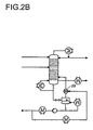
- FIG. 2 is a combination of side stream and evaporator shown.
- the countercurrent rectification column (20) is fed via line (21) of the feed and line (22), the ionic liquid as Entrainer. Via line (23), the top stream is discharged.
- the bottom stream is fed to an evaporator (25), in which the separation of the ionic liquid according to the invention takes place.
- the thus obtained ionic liquid can be recycled via line (26) again in the countercurrent rectification column.
- Via the side stream (27) additionally present in a preferred embodiment, vaporous high boiler is withdrawn from the column (20), whereby the separation is further improved.
- FIG. 2a is building on FIG. 2 in the evaporator, the condenser with subsequent liquid pump has been replaced by a compressor (28).
- the compressed to ambient pressure Schwersiederbrüden be liquefied in a condenser.
- FIG. 2b is building on Figures 2 and 2a used as a compressor, a liquid ring pump (29). Part of the ionic liquid exiting the evaporator is cooled and passed as a ring liquid to the liquid ring pump. This is operated in continuous operation. The resulting at ambient pressure mixture of IF and SS is returned to the stripping section.
- FIG. 3 is a combination of side stream and stripping column to see.
- the countercurrent rectification column (30) is fed via line (31) of the feed and line (32), the ionic liquid as Entrainer. Via line (33), the top stream is discharged. By means of line (34), the bottom stream is fed to a stripper (35), in which the separation of the ionic liquid according to the invention takes place.
- inert gas is introduced into the stripper via line (38) and the inert gas and high-boiling point-containing gas mixture are discharged via line (39).
- portions of the high boiler are deposited in a dephlegmator.
- the thus obtained ionic liquid can be recycled via line (36) again in the countercurrent rectification column.
- a heat exchanger is necessary in order to cool the IF to the appropriate temperature before re-charging to the extractive rectification column.
- the sidestream significantly reduces the cooling capacity and size of the dephlegmator in addition to the changes in the stripper. Since only part of the high boiler exits via the top stream of the stripper, it may be worthwhile in individual cases to dispose of this portion of the high boiler with the inert gas, ie not to condense it. Then the necessary for the condensation chiller can be saved including the required energy for compressor and cooling. Whether the reduction of investment and operating costs by saving the dephlegmator with a chiller outweighs the cost of the loss of high boiler results in a cost accounting and depends on the respective material system. The same applies to the side stream. If it is economical with the stripper variant, must be evaluated by a cost accounting for the individual case.
- superheated steam is used as "inert gas" for purifying the IF in the stripper.
- side stream as already mentioned above, the required amount of steam is relatively small.
- the stripping head stream can be completely condensed in this variant, since it contains no real inert gas.
- the liquid stream thus produced contains a mixture of LS and SS, which is fed to the extractive rectification at the appropriate point and thus worked up again.
- the high boiler is discharged via the side stream only.
- no chiller is needed for the condensation. It can be cooled with cheap cooling water. In addition, no high boiler is lost.
- the version with stripper and side stream is particularly beneficial in systems where the high boiler is water. Then, since the stripper head outlet contains only water and inert gas, it can be easily released into the ambient air. Since water is already included in the system, the inert gas may not need to be dried. Whether drying is necessary must be decided on the basis of the maximum permissible concentration of water in the IF returned from the stripping sump. This is, as stated above, determined by the water concentration in the incoming inert gas and affects the water contamination in the distillate of the column.
- the process according to the invention offers a procedurally simple and economic possibility of working up the bottoms stream from the extractive rectification. With little expenditure on apparatus, ionic liquid can be obtained in high purity. The temperatures required for the separation are relatively low, which also avoids unwanted decomposition of the ionic liquid in addition to a reduction in energy consumption. The thus obtained ionic liquid can be returned to the column again and find there again as Entrainer use.
- Version only side stream without additional work-up of the bottom stream If the loaded with residues to SS IF added directly to the head of the extractive rectification (circulation of the IF), so a part of the SS at the top will enter the vapor phase and contaminate the top product (LS) , If the purity requirements for the LS are moderate, then depletion of the SS in the IF alone by a side stream may well be sufficient, and no further processing of the IF is needed.
- an azeotrope or narrow-boiling mixture would be separated by addition of an IF in a column with side stream without further additional equipment in light and high boiler. Compared to a normal extractive rectification, which always requires a second column to work up the entrainer, this means a considerable saving in investment costs.
- the feed to the extractive rectification column was 844 kg / h of a binary mixture consisting of 77% TMB (trimethyl borate) and 23% methanol.
- the feed bottom was always at level 12.
- the experiments were always adjusted so that 650 kg / h of TMB with a residual content of 500 ppm of methanol were obtained as top product.
- the IF (1-ethyl-3-methyl-imidazolium tosylate) was charged at 1441 kg / h. It contained 103 ppm of methanol. Head and bottom temperatures reached 67 and 95.4 ° C, respectively.
- the bottom product was a stream of 1635 kg / h with 88% IF and 12% methanol.
- the bottom product was fed into the downstream evaporator. The was operated at 1 bar and 180 ° C. The resulting vapor was condensed in a condenser at 1 bar and 64.6 ° C. The evaporator vapors were pure methanol at 179 kg / h.
- the sump outlet was 1456 kg / h with 99% IF and 1% methanol.
- column condenser 90 kW
- column evaporator 134 kW
- downstream evaporator 182 kW
- evaporator stage condenser 64 kW.
- the sump outlet of the evaporator should actually be recycled as purified IF for extractive rectification. It still contains 1% methanol in this variant. If this stream were actually used again as entrainer in the extractive rectification, the head purity of 500 ppm methanol would not be achievable. In this version, the bottom discharge of the evaporator must be discarded and the extractive rectification constantly fresh IF be supplied. Such a method does not make economic sense.
- Example 1 The extractor rectification downstream evaporator was operated at 10 mbar and 180 ° C. The evaporator vapors were completely condensed in the condenser at -19.5 ° C. A pure methanol flow of 194 kg / h much on it. In the downstream evaporator and condenser an amount of energy of 185 kW or 81 kW was transmitted.
- Example 1 Only the properties deviating from Example 1 are listed here:
- the entrainers were 1523 kg / h of IF which had been contaminated with 1 ppm of methanol.
- the bottom product of the extractive rectification was a flow of 1717 kg / h with 89% IF and 11% methanol. He was put on the head of the stripper, which had a total of 9 stages and was operated at 1 bar. 2305 kg / h of dried air preheated to 180 ° C. were added to the stripper bottom.
- the stripper overhead stream was fed to a dephlegmator, which at -5.4 ° C deposited much of the vaporous methanol. Liquid in the dephlegmator 122 kg / h of methanol.
- the bottom effluent of the stripper was 1523 kg / h IF with a residual loading on Methanol of 1 ppm.
- the amounts of energy required in the heat exchangers were: Column evaporator: 138 kW, stripping air preheating: 100 kW, Dephlegmator of the stripper: 88 kW.
- the downstream stripper can reduce the residual content of methanol in the returned ionic liquid down to 1 ppm. This value is significantly lower than in Example 2 (version with evaporator at 10 mbar). In order to achieve this value in the evaporator version, much higher temperatures or lower pressures would have to be set there. For separation tasks where particularly high head clearances in the extractive rectification are required, the stripper variant of the evaporator variant is superior.
- the amount of entrainer supplied was 1384 kg / h IF with a residual content of 103 ppm methanol. 179 kg / h of pure methanol were taken off in vapor form as side stream from the bottom and then condensed at 64.6 ° C. The bottom temperature increased to 180 ° C. The bottom product of the column was 1399 kg / h with 99% IF and 1% methanol.
- the evaporator was operated at 10 mbar and 180 ° C and the condenser at -19.5 ° C. The evaporator vapors were 15 kg / h and passed from 100% methanol.
- the evaporator sump (reflux IF) was 1384 kg / h IF with a residual content of 103 ppm methanol.
- the energy quantities of the heat exchangers were: column evaporator: 301 kW, side flow condenser: 60 kW, downstream evaporator: 4 kW, condenser: 6 kW.
- Example 2 As in Example 2, the necessary purity in the bottom discharge of the downstream evaporator is achieved and the IF can be recycled.
- the heat to be dissipated at -19.5 ° C. in the condenser of the downstream evaporator is substantially lower due to the side stream. This is advantageous, the cooling energy is much more expensive than steam.
- the amount of IF required circulation decreases and the methanol loss is low.
- the liquid ring pump was used to adjust the 10 mbar in the downstream evaporator and to compress the extracted methanol to ambient pressure.
- the pump was operated with IF as pumping liquid.
- IF pumping liquid.
- a portion of the exiting from the bottom of the downstream evaporator IF branched off and cooled to 28 ° C. This IF was fed to the liquid ring pump.
- the effluent at ambient pressure of 102.6 kg / h contains 97.5% IF and 2.5% methanol. He was returned to the swamp of extractive rectification.
- the chiller is replaced by a liquid ring pump.
- the temperature of 28 ° C which can be achieved with inexpensive cooling water, is sufficient to condense much of the methanol. As the amount of gas decreases, so does the required compaction energy. All of the methanol can be removed via the vapor side take-off.
- the required for the liquid ring pump IF current is only about 7% of the total IF recycle stream. The system is simplified and the investment and operating costs are reduced.
- Example 1 or 3 As entrainers, 1364 kg / h of IF were added to the column. 179 kg / h of pure methanol was taken as a vapor side stream to the bottom of the column and then condensed. The bottom temperature was 180 ° C. The bottoms product was 1378 kg / h of a mixture of 99% IF and 1% methanol. This was given to the head of the stripper. The air flow was 34 kg / h. He was dried but not preheated. The stripper vapors were fed to a dephlegmator. There, 35 kg / h of methanol were condensed out at -5.4 ° C.
- the bottom product of the stripper was 1364 kg of IF with a residual charge of 1 ppm of methanol.
- the energy quantities of the heat exchangers were: column evaporator: 299 kW, side-flow condenser: 60 kW, dephlegmator 7 kW.
- Example 3 In this particularly advantageous version significantly less air is consumed compared to Example 3. This also reduces the refrigeration demand of the dephlegmator. In addition, the air does not have to be preheated.
- the IF obtained in the bottom of the stripper again has a very good purity and can be reused directly in the extractive rectification.
Abstract
Description
Die vorliegende Erfindung betrifft ein verbessertes Verfahren zur Aufarbeitung eines Sumpfstromes enthaltend Schwersieder und ionische Flüssigkeiten (IF) aus einer Extraktiv-Rektifikation.The present invention relates to an improved process for working up a bottoms stream comprising high boilers and ionic liquids (IF) from an extractive rectification.
In der Industrie treten eine Vielzahl von Flüssigmischungen auf, die sich nicht durch konventionelle Rektifikation, sondern vorzugsweise durch Extraktiv-Rektifikation [
Der Trennaufwand für eine binäre - aus den Komponenten i und j bestehende - Flüssigmischung bei der Rektifikation spiegelt sich im sogenannten Trennfaktor αij, dem Verhältnis der Verteilungskoeffizienten der Komponenten i und j, wider. Je näher der Trennfaktor dem Wert eins kommt, desto aufwendiger wird die Trennung der Gemischkomponenten mittels konventioneller Rektifikation, da entweder die Trennstufenanzahl der Rektifikationskolonne und/oder das Rücklaufverhältnis im Kolonnenkopf vergrößert werden muss. Nimmt der Trennfaktor den Wert eins an, so liegt ein azeotroper Punkt vor, und die weitere Aufkonzentrierung der Gemischkomponenten ist auch durch eine Erhöhung der Trennstufenzahl oder des Rücklaufverhältnisses nicht mehr möglich. Generell ist bei der Verwendung des Trennfaktors zu beachten, dass er größer oder kleiner 1 sein kann, je nachdem ob der Verteilungskoeffizient des Leichtsieders im Zähler oder im Nenner steht. Normalerweise wird der Leichtsieder im Zähler aufgetragen, so dass der Trennfaktor größer 1 ist.The separation effort for a binary liquid mixture consisting of components i and j in the rectification is reflected in the so-called separation factor α ij , the ratio of the distribution coefficients of the components i and j. The closer the separation factor is to unity, the more complex the separation of the mixture components by means of conventional rectification, since either the separation stage number of the rectification column and / or the reflux ratio in the column head must be increased. If the separation factor assumes the value one, then there is an azeotropic point, and the further concentration of the mixture components is no longer possible even by increasing the number of separation stages or the reflux ratio. In general, when using the separation factor, it should be noted that it may be larger or smaller than 1, depending on whether the distribution coefficient of the low boiler is in the numerator or in the denominator. Normally, the low boilers are applied in the meter so that the separation factor is greater than one.
Ein in der Industrie häufig praktiziertes Vorgehen zur Trennung engsiedender -hierbei wird ein Trennfaktor etwa kleiner 1,2 verstanden - oder azeotroper Systeme stellt die Zugabe eines selektiven Zusatzstoffes, des sogenannten Entrainers, in einer Extraktiv-Rektifikation dar. Ein geeigneter Zusatzstoff beeinflusst durch selektive Wechselwirkungen mit einer oder mehreren der Gemischkomponenten den Trennfaktor, so dass die Auftrennung der engsiedenden oder azeotrop-siedenden Gemischkomponenten ermöglicht wird. Die Kopfkomponente ist die in Anwesenheit des Entrainers leichter siedende Komponente und im Sumpf befindet sich die in Anwesenheit des Entrainers schwerer siedenden Komponenten.An often practiced procedure in the industry for separating more densely - here a separation factor is understood as less than 1.2 - or azeotropic systems represents the addition of a selective additive, the so-called entrainers, in an extractive rectification. A suitable additive influenced by selective interactions with one or more of the mixture components the separation factor, so that the separation of the dense or azeotropic-boiling mixture components is made possible. The head component is the lower boiling component in the presence of the entrainer, and in the sump is the components boiling heavier in the presence of the entrainer.
Ein Gütemaß für die Intensität der Wechselwirkungen des Entrainers mit einer oder mehreren der Gemischkomponenten stellt die sogenannte Selektivität dar. Die Selektivität ist definiert als das Verhältnis aus Grenzaktivitätskoeffzient der Komponente i zu Grenzaktivitätskoeffizient der Komponente j, wobei die Komponenten i und j im Entrainer unendlich verdünnt vorliegen [
Im der Patentschrift
Ein erster Gegenstand der Erfindung ist ein Verfahren zur Aufarbeitung eines Sumpfstromes enthaltend ein oder mehrere Schwersieder und ionische Flüssigkeit aus einer Extraktiv-Rektifikation, bei welcher die ionische Flüssigkeit als Entrainer eingesetzt wird, dadurch gekennzeichnet, dass man den Sumpfstrom einer Verdampferstufe zuführt, welche bei einem Druck kleiner als 500 mbar betrieben wird, wobei man den enthaltenen Schwersieder größtenteils dampfförmig von der ionischen Flüssigkeit abtrennt, so dass der Schwersiedergehalt in der Ionischen Flüssigkeit auf Konzentrationen kleiner 5 Gew.-% absinkt, wobei man die aufbereitete ionische Flüssigkeit im Anschluss einem mit Inertgas oder überhitztem Dampf beaufschlagten Stripper zuführt, weicher bei Umgebungsdruck betrieben wird.A first object of the invention is a process for working up a bottom stream containing one or more high boilers and ionic liquid from an extractive rectification, in which the ionic liquid is used as Entrainer, characterized in that one feeds the bottom stream of an evaporator stage, which in a Pressure is operated less than 500 mbar, wherein the high boilers contained largely vapor-separated from the ionic liquid, so that the high-boiling content in the ionic liquid to concentrations less than 5 wt .-% drops, wherein the treated ionic liquid in the connection with an inert gas or superheated steam applied stripper, which is operated at ambient pressure.
Ein zweiter Gegenstand der Erfindung ist ein Verfahren zur Aufarbeitung eines Sumpfstromes enthaltend ein oder mehrere Schwersieder und ionische Flüssigkeit aus einer Extraktiv-Rektifikation, bei welcher die ionische Flüssigkeit als Entrainer eingesetzt wird, dadurch gekennzeichnet, dass man den Sumpfstrom einer Verdampferstufe zuführt, welche bei einem Druck kleiner als 500 mbar betrieben wird, wobei man den enthaltenen Schwersieder größtenteils dampfförmig von der ionischen Flüssigkeit abtrennt, so dass der Schwersiedergehalt in der Ionischen Flüssigkeit auf Konzentrationen kleiner 5 Gew.-% absinkt, wobei man die aufbereitete ionische Flüssigkeit im Anschluss einem mit Inertgas oder überhitztem Dampf beaufschlagten Stripper zuführt, welcher bei einem Druck kleiner als 900mbar, besonders bevorzugt kleiner 500mbar betrieben wird.A second subject of the invention is a process for working up a bottom stream comprising one or more high boilers and ionic liquid from an extractive rectification, in which the ionic liquid is used as entrainer, characterized in that the bottom stream is fed to an evaporator stage which is at a Pressure is operated less than 500 mbar, wherein the high boilers contained largely vapor-separated from the ionic liquid, so that the high-boiling content in the ionic liquid to concentrations less than 5 wt .-% drops, wherein the treated ionic liquid in the connection with an inert gas or supercharged steam supplied to stripper, which is operated at a pressure of less than 900 mbar, more preferably less than 500 mbar.
Ein dritter Gegenstand der Erfindung ist ein Verfahren zur Aufarbeitung eines Sumpfstromes enthaltend ein oder mehrere Schwersieder und ionische Flüssigkeit aus einer Extraktiv-Rektifikation, bei welcher die ionische Flüssigkeit als Entrainer eingesetzt wird, dadurch gekennzeichnet, dass man den Sumpfstrom einem mit überhitztem Dampf, welcher den Leichtsieder enthält, beaufschlagten Stripper zuführt, welcher bei Umgebungsdruck oder bei einem Druck kleiner 900 mbar betrieben wird.A third aspect of the invention is a process for working up a bottoms stream comprising one or more high boilers and ionic liquid from an extractive rectification, in which the ionic liquid is used as Entrainer, characterized in that the bottom stream with a superheated steam, the Contains low boilers, supplied to acted stripper, which is operated at ambient pressure or at a pressure of less than 900 mbar.
Unter ionischen Flüssigkeiten werden solche verstanden, wie sie von
Ionische Flüssigkeiten sind im Vergleich zu ionischen Salzen bei wesentlich geringeren Temperaturen (in der Regel unterhalb von 200°C,) flüssig und besitzen häufig einen Schmelzpunkt unterhalb von 0°C, im Einzelfall bis -96°C, was wichtig für die industrielle Umsetzung der Extraktiv-Rektifikation ist.Ionic liquids are compared to ionic salts at much lower temperatures (usually below 200 ° C,) liquid and often have a melting point below 0 ° C, in individual cases down to -96 ° C, which is important for the industrial implementation of Extractive rectification is.
Darüber hinaus sind ionische Flüssigkeiten in der Regel nicht brennbar, nicht korrosiv und wenig viskos und zeichnen sich durch einen nicht messbaren Dampfdruck aus. Als ionische Flüssigkeiten werden erfindungsgemäß solche Verbindungen bezeichnet, die mindestens eine positive und mindestens eine negative Ladung aufweisen, insgesamt jedoch ladungsneutral sind, und einen Schmelzpunkt unter 200°C aufweisen, bevorzugt unter 100, besonders bevorzugt unter Umgebungstemperatur.In addition, ionic liquids are usually non-flammable, non-corrosive and less viscous and are characterized by a non-measurable vapor pressure. According to the invention, ionic liquids are those compounds which have at least one positive and at least one negative charge but are overall charge-neutral, and have a melting point below 200 ° C., preferably below 100, more preferably below ambient temperature.
Die Ionischen Flüssigkeiten können auch mehrere positive oder negative Ladungen aufweisen, beispielsweise 1 bis 5, bevorzugt 1 bis 4, besonders bevorzugt 1 bis 3, ganz besonders bevorzugt 1 bis 2, insbesondere jedoch je eine positive und negative Ladung.The ionic liquids may also have a plurality of positive or negative charges, for example 1 to 5, preferably 1 to 4, more preferably 1 to 3, most preferably 1 to 2, but in particular one positive and one negative charge.
Die Ladungen können sich an verschiedenen lokalisierten oder delokalisierten Bereichen innerhalb eines Moleküls befinden, also betainartig, oder auf je ein getrenntes Anion und Kation verteilt sein. Bevorzugt sind solche Ionischen Flüssigkeiten, die aus mindestens einem Kation und mindestens einem Anion aufgebaut sind. Kation und Anion können, wie oben ausgeführt, ein oder mehrfach, bevorzugt einfach geladen sein.The charges may be located at different localized or delocalized regions within a molecule, that is, betaine-like, or distributed to a separate anion and cation each. Preference is given to those ionic liquids which are composed of at least one cation and at least one anion. Cation and anion can, as stated above, be one or more times, preferably simply charged.
Selbstverständlich sind auch Gemische verschiedener ionischer Flüssigkeiten oder Mischungen aus herkömmlichen Entrainern, wie n-Methylpyrrolidon, Dimethylformamid, Ethandiol, Benzol, Cyclohexan, Wasser usw., mit Ionischen Flüssigkeiten denkbar.Of course, mixtures of different ionic liquids or mixtures of conventional entrainers, such as n-methylpyrrolidone, dimethylformamide, ethanediol, benzene, cyclohexane, water, etc., with ionic liquids are conceivable.
Bevorzugt als Kation sind Ammonium- oder Phosphoniumionen, oder solche Kationen, die mindestens einen fünf- bis sechsgliedrigen Heterocyclus enthalten, der mindestens ein Phosphor- oder Stickstoffatom sowie gegebenenfalls ein Sauerstoff- oder Schwefelatom aufweist, besonders bevorzugt solche Verbindungen, die mindestens einen fünf- bis sechsgliedrigen Heterocyclus enthalten, der ein, zwei oder drei Stickstoffatome und ein Schwefel- oder ein Sauerstoffatom aufweist, ganz besonders bevorzugt solche mit ein oder zwei Stickstoffatomen.Preferred as a cation are ammonium or phosphonium ions, or such cations containing at least one 5- to 6-membered heterocycle having at least one phosphorus or nitrogen atom and optionally an oxygen or sulfur atom, more preferably those compounds having at least one five- to containing six-membered heterocycle having one, two or three nitrogen atoms and a sulfur or an oxygen atom, most preferably those having one or two nitrogen atoms.
Besonders bevorzugte Ionische Flüssigkeiten sind solche, die ein Molgewicht unter 1000 g/mol aufweisen, ganz besonders bevorzugt unter 350 g/mol.Particularly preferred ionic liquids are those which have a molecular weight of less than 1000 g / mol, very particularly preferably less than 350 g / mol.
Weiterhin sind solche Kationen bevorzugt, die ausgewählt sind aus den Verbindungen der Formeln (Ia) bis (Iw),


worin
- R1, R2, R3, R4, R5, R6 und R7 unabhängig voneinander jeweils C1 - C18-Alkyl, gegebenenfalls durch ein oder mehrere Sauerstoff- und/oder Schwefelatome und/oder ein oder mehrere substituierte oder unsubstituierte Iminogruppen unterbrochenes C2 - C18-Alkyl, C6 - C12-Aryl, C5 - C12-Cycloalkyl oder einen fünf- bis sechsgliedrigen, Sauerstoff-, Stickstoff- und/oder Schwefelatome aufweisenden Heterocyclus bedeuten oder zwei von ihnen gemeinsam einen ungesättigten, gesättigten oder aromatischen und gegebenenfalls durch ein oder mehrere Sauerstoff- und/oder Schwefelatome und/oder ein oder mehrere substituierte oder unsubstituierte Iminogruppen unterbrochenen Ring bilden, wobei die genannten Reste jeweils durch funktionelle Gruppen, Aryl, Alkyl, Aryloxy, Alkyloxy, Halogen, Heteroatome und/oder Heterocyclen substituiert sein können.
- R1, R2, R3, R4, R5 und R6 können zusätzlich dazu Wasserstoff bedeuten.
- R7 kann darüberhinaus C1 - C18-Alkyloyl (Alkylcarbonyl), C1 - C18- Alkyloxycarbonyl, C5 - C12-Cycloalkylcarbonyl oder C6 - C12-Aryloyl (Arylcarbonyl) bedeuten, wobei die genannten Reste jeweils durch funktionelle Gruppen, Aryl, Alkyl, Aryloxy, Alkyloxy, Halogen, Heteroatome und/oder Heterocyclen substituiert sein können.
wherein
- R 1 , R 2 , R 3 , R 4 , R 5 , R 6 and R 7 are each independently C 1 - C 18 alkyl, optionally substituted by one or more oxygen and / or sulfur atoms and / or one or more substituted or unsubstituted imino groups interrupted C 2 - C 18 alkyl, C 6 - C 12 aryl, C 5 - C 12 cycloalkyl or a five- to six-membered, oxygen, nitrogen and / or sulfur-containing heterocycle or two of them together form an unsaturated, saturated or aromatic ring optionally interrupted by one or more oxygen and / or sulfur atoms and / or one or more substituted or unsubstituted imino groups, where the radicals mentioned are in each case denoted by functional groups, aryl, alkyl, aryloxy, alkyloxy, halogen , Heteroatoms and / or heterocycles may be substituted.
- R 1 , R 2 , R 3 , R 4 , R 5 and R 6 may additionally denote hydrogen.
- R 7 can moreover be C 1 -C 18 -alkyloyl (alkylcarbonyl), C 1 -C 18 -alkyloxycarbonyl, C 5 -C 12 -cycloalkylcarbonyl or C 6 -C 12 -aryloyl (arylcarbonyl), where the radicals mentioned are in each case represented by functional groups Groups, aryl, alkyl, aryloxy, alkyloxy, halogen, heteroatoms and / or heterocycles may be substituted.
Darin bedeuten
gegebenenfalls durch funktionelle Gruppen, Aryl, Alkyl, Aryloxy, Alkyloxy, Halogen, Heteroatome und/oder Heterocyclen substituiertes C1 - C18-Alkyl beispielsweise Methyl, Ethyl, Propyl, Isopropyl, n-Butyl, sec-Butyl, tert.-Butyl, Pentyl, Hexyl, Heptyl, Octyl, 2-Etylhexyl, 2,4,4-Trimethylpentyl, Decyl, Dodecyl, Tetradecyl, Hetadecyl, Octadecyl, 1,1-Dimethylpropyl, 1,1-Dimethylbutyl, 1,1,3,3-Tetramethylbutyl, Benzyl, 1-Phenylethyl, 2-Phenylethyl, α,α-Dimethylbenzyl, Benzhydryl, p-Tolylmethyl,1-(p-Butylphenyl)-ethyl, p-Chlorbenzyl, 2,4-Dichlorbenzyl, p-Methoxybenzyl, m-Ethoxybenzyl, 2-Cyanoethyl, 2-Cyanopropyl, 2-Methoxycarbonethyl, 2-Ethoxycarbonylethyl, 2-Butoxycarbonylpropyl, 1,2-Di-(methoxycarbonyl)-ethyl, 2-Methoxyethyl, 2-Ethoxyethyl, 2-Butoxyethyl, Diethoxymethyl, Diethoxyethyl, 1,3-Dioxolan-2-yl, 1,3-Dioxan-2-yl, 2-Methyl-1,3-dioxolan-2-yl, 4-Methyl-1,3-dioxolan-2-yl, 2-Isopropoxyethyl, 2-Butoxypropyl, 2-Octyloxyethyl, Chlormethyl, 2-Chlorethyl, Trichlormethyl, Trifluormethyl, 1,1-Dimethyl-2-chlorethyl, 2-Methoxyisopropyl, 2-Ethoxyethyl, Butylthiomethyl, 2-Dodecylthioethyl, 2-Phenylthioethyl, 2,2,2-Trifluorethyl, 2-Hydroxyethyl, 2-Hydroxypropyl, 3-Hydroxypropyl, 4-Hydroxybutyl, 6-Hydroxyhexyl, 2-Aminoethyl, 2-Aminopropyl, 3-Aminopropyl, 4-Aminobutyl, 6-Aminohexyl, 2-Methylaminoethyl, 2-Methylaminopropyl, 3-Methylaminopropyl, 4-Methylaminobutyl, 6-Methylaminohexyl, 2-Dimethylaminoethyl, 2-Dimethylaminopropyl, 3-Dimethylaminopropyl, 4-Dimethylaminobutyl, 6-Dimethylaminohexyl, 2-Hydroxy-2,2-dimethylethyl, 2-Phenoxyethyl, 2-Phenoxypropyl, 3-Phenoxypropyl, 4-Phenoxybutyl, 6-Phenoxyhexyl, 2-Methoxyethyl, 2-Methoxypropyl, 3-Methoxypropyl, 4-Methoxybutyl, 6-Methoxyhexyl, 2-Ethoxyethyl, 2-Ethoxypropyl, 3-Ethoxypropyl, 4-Ethoxybutyl oder 6-Ethoxyhexyl und,
gegebenenfalls durch ein oder mehrere Sauerstoff- und/oder Schwefelatome und/oder ein oder mehrere substituierte oder unsubstituierte Iminogruppen unterbrochenes C2 - C18-Alkyl beispielsweise 5-Hydroxy-3-oxa-pentyl, 8-Hydroxy-3,6-dioxa-octyl, 11-Hydroxy-3,6,9-trioxa-undecyl, 7-Hydroxy-4-oxa-heptyl, 11-Hydroxy-4,8-dioxa-undecyl, 15-Hydroxy-4,8,12-trioxa-pentadecyl, 9-Hydroxy-5-oxa-nonyl, 14-Hydroxy-5,10-oxa-tetradecyl, 5-Methoxy-3-oxa-pentyl, 8-Methoxy-3,6-dioxa-octyl, 11-Methoxy-3,6,9-trioxa-undecyl, 7-Methoxy-4-oxa-heptyl, 11-Methoxy-4,8-dioxa-undecyl, 15-Methoxy-4,8,12-trioxa-pentadecyl, 9-Methoxy-5-oxa-nonyl, 14-Methoxy-5,10-oxa-tetradecyl, 5-Ethoxy-3-oxa-pentyl, 8-Ethoxy-3,6-dioxa-octyl, 11-Ethoxy-3,6,9-trioxa-undecyl, 7-Ethoxy-4-oxa-heptyl, 11-Ethoxy-4,8-dioxa-undecyl, 15-Ethoxy-4,8,12-trioxa-pentadecyl, 9-Ethoxy-5-oxa-nonyl oder 14-Ethoxy-5,10-oxa-tetradecyl.Mean in it
optionally C 1 -C 18 -alkyl substituted by functional groups, aryl, alkyl, aryloxy, alkyloxy, halogen, heteroatoms and / or heterocycles, for example methyl, ethyl, propyl, isopropyl, n-butyl, sec-butyl, tert-butyl, Pentyl, hexyl, heptyl, octyl, 2-ethylhexyl, 2,4,4-trimethylpentyl, decyl, dodecyl, tetradecyl, heptadecyl, octadecyl, 1,1-dimethylpropyl, 1,1-dimethylbutyl, 1,1,3,3- Tetramethylbutyl, benzyl, 1-phenylethyl, 2-phenylethyl, α, α-dimethylbenzyl, benzhydryl, p-tolylmethyl, 1- (p-butylphenyl) -ethyl, p-chlorobenzyl, 2,4-dichlorobenzyl, p-methoxybenzyl, m- Ethoxybenzyl, 2-cyanoethyl, 2-cyanopropyl, 2-methoxycarbonethyl, 2-ethoxycarbonylethyl, 2-butoxycarbonylpropyl, 1,2-di- (methoxycarbonyl) -ethyl, 2-methoxyethyl, 2-ethoxyethyl, 2-butoxyethyl, diethoxymethyl, diethoxyethyl, 1,3-dioxolan-2-yl, 1,3-dioxan-2-yl, 2-methyl-1,3-dioxolan-2-yl, 4-methyl-1,3-dioxolan-2-yl, 2- Isopropoxyethyl, 2-butoxypropyl, 2-octyloxyethyl, chloromethyl, 2-chloroethyl, trichloromethyl, trifluoromethyl , 1,1-dimethyl-2-chloroethyl, 2-methoxyisopropyl, 2-ethoxyethyl, butylthiomethyl, 2-dodecylthioethyl, 2-phenylthioethyl, 2,2,2-trifluoroethyl, 2-hydroxyethyl, 2-hydroxypropyl, 3-hydroxypropyl, 4 Hydroxybutyl, 6-hydroxyhexyl, 2-aminoethyl, 2-aminopropyl, 3-aminopropyl, 4-aminobutyl, 6-aminohexyl, 2-methylaminoethyl, 2-methylaminopropyl, 3-methylaminopropyl, 4-methylaminobutyl, 6-methylaminohexyl, 2-dimethylaminoethyl , 2-dimethylaminopropyl, 3-dimethylaminopropyl, 4-dimethylaminobutyl, 6-dimethylaminohexyl, 2-hydroxy-2,2-dimethylethyl, 2-phenoxyethyl, 2-phenoxypropyl, 3-phenoxypropyl, 4-phenoxybutyl, 6-phenoxyhexyl, 2-methoxyethyl , 2-methoxypropyl, 3-methoxypropyl, 4-methoxybutyl, 6-methoxyhexyl, 2-ethoxyethyl, 2-ethoxypropyl, 3-ethoxypropyl, 4-ethoxybutyl or 6-ethoxyhexyl and,
optionally interrupted by one or more oxygen and / or sulfur atoms and / or one or more substituted or unsubstituted imino C 2 - C 18 -alkyl, for example, 5-hydroxy-3-oxa-pentyl, 8-hydroxy-3,6-dioxa- octyl, 11-hydroxy-3,6,9-trioxa-undecyl, 7-hydroxy-4-oxa-heptyl, 11-hydroxy-4,8-dioxa-undecyl, 15-hydroxy-4,8,12-trioxa pentadecyl, 9-hydroxy-5-oxa-nonyl, 14-hydroxy-5,10-oxa-tetradecyl, 5-methoxy-3-oxa-pentyl, 8-methoxy-3,6-dioxo-octyl, 11-
Bilden zwei Reste einen Ring, so können diese Reste gemeinsam bedeuten 1,3-Propylen, 1,4-Butylen, 2-Oxa-1,3-propylen, 1-Oxa-1,3-propylen, 2-Oxa-1,3-propylen, 1-Oxa-1,3-propenylen, 1-Aza-1,3-propenylen, 1-C1-C4-Alkyl-1-aza-1,3-propenylen, 1,4-Buta-1,3-dienylen, 1-Aza-1,4-buta-1,3-dienylen oder 2-Aza-1,4-buta-1,3-dienylen.If two radicals form a ring, these radicals may together be 1,3-propylene, 1,4-butylene, 2-oxa-1,3-propylene, 1-oxa-1,3-propylene, 2-oxa-1, 3-propylene, 1-oxa-1,3-propenylene, 1-aza-1,3-propenylene, 1-C 1 -C 4 -alkyl-1-aza-1,3-propenylene, 1,4-
Die Anzahl der Sauerstoff- und/oder Schwefelatome und/oder Iminogruppen ist nicht beschränkt. In der Regel beträgt sie nicht mehr als 5 in dem Rest, bevorzugt nicht mehr als 4 und ganz besonders bevorzugt nicht mehr als 3.The number of oxygen and / or sulfur atoms and / or imino groups is not limited. As a rule, it is not more than 5 in the radical, preferably not more than 4, and very particularly preferably not more than 3.
Weiterhin befinden sich zwischen zwei Heteroatomen in der Regel mindestens ein Kohlenstoffatom, bevorzugt mindestens zwei.Furthermore, at least one carbon atom, preferably at least two, is usually present between two heteroatoms.
Substituierte und unsubstituierte Iminogruppen können beispielsweise Imino-, Methylimino-, iso-Propylimino, n-Butylimino oder tert-Butylimino sein.Substituted and unsubstituted imino groups may be, for example, imino, methylimino, iso-propylimino, n-butylimino or tert-butylimino.
Weiterhin bedeuten
funktionelle Gruppen Carboxy, Carboxamid, Hydroxy, Di-(C1-C4-Alkyl)-amino, C1-C4-Alkyloxycarbonyl, Cyano oder C1-C4-Alkyloxy,
gegebenenfalls durch funktionelle Gruppen, Aryl, Alkyl, Aryloxy, Alkyloxy, Halogen, Heteroatome und/oder Heterocyclen substituiertes C6 - C12-Aryl beispielsweise Phenyl, Tolyl, Xylyl, α-Naphthyl, β-Naphthyl, 4-Diphenylyl, Chlorphenyl, Dichlorphenyl, Trichlorphenyl, Difluorphenyl, Methylphenyl, Dimethylphenyl, Trimethylphenyl, Ethylphenyl, Diethylphenyl, iso-Propylphenyl, tert.-Butylphenyl, Dodecylphenyl, Methoxyphenyl, Dimethoxyphenyl, Ethoxyphenyl, Hexyloxyphenyl, Methylnaphthyl, Isopropylnaphthyl, Chlornaphthyl, Ethoxynaphthyl, 2,6-Dimethylphenyl, 2,4,6-Trimethylphenyl, 2,6-Dimethoxyphenyl, 2,6-Dichlorphenyl, 4-Bromphenyl, 2- oder 4-Nitrophenyl, 2,4- oder 2,6-Dinitrophenyl, 4-Dimethylaminophenyl, 4-Acetylphenyl, Methoxyethylphenyl oder Ethoxymethylphenyl,
gegebenenfalls durch funktionelle Gruppen, Aryl, Alkyl, Aryloxy, Alkyloxy, Halogen, Heteroatome und/oder Heterocyclen substituiertes C5 - C12-Cycloalkyl beispielsweise Cyclopentyl, Cyclohexyl, Cyclooctyl, Cyclododecyl, Methylcyclopentyl, Dimethylcyclopentyl, Methylcyclohexyl, Dimethylcyclohexyl, Diethylcyclohexyl, Butylcyclohexyl, Methoxycyclohexyl, Dimethoxycyclohexyl, Diethoxycyclohexyl, Butylthiocyclohexyl, Chlorcyclohexyl, Dichlorcyclohexyl, Dichlorcyclopentyl sowie ein gesättigtes oder ungesättigtes bicyclisches System wie z.B. Norbornyl oder Norbornenyl,
ein fünf- bis sechsgliedriger, Sauerstoff-, Stickstoff- und/oder Schwefelatome aufweisender Heterocyclus beispielsweise Furyl, Thiophenyl, Pyrryl, Pyridyl, Indolyl, Benzoxazolyl, Dioxolyl, Dioxyl, Benzimidazolyl, Benzthiazolyl, Dimethylpyridyl, Methylchinolyl, Dimethylpyrryl, Methoxyfuryl, Dimethoxypyridyl, Difluorpyridyl, Methylthiophenyl, Isopropylthiophenyl oder tert.-Butylthiophenyl undFurthermore mean
carboxy, carboxamide, hydroxy, di (C 1 -C 4 alkyl) amino, C 1 -C 4 alkyloxycarbonyl, cyano or C 1 -C 4 alkyloxy functional groups,
C 6 -C 12 aryl optionally substituted by functional groups, aryl, alkyl, aryloxy, alkyloxy, halogen, heteroatoms and / or heterocycles, for example phenyl, tolyl, xylyl, α-naphthyl, β-naphthyl, 4-diphenylyl, chlorophenyl, dichlorophenyl , Trichlorophenyl, difluorophenyl, methylphenyl, dimethylphenyl, trimethylphenyl, ethylphenyl, diethylphenyl, iso-propylphenyl, tert-butylphenyl, dodecylphenyl, methoxyphenyl, dimethoxyphenyl, ethoxyphenyl, hexyloxyphenyl, methylnaphthyl, isopropylnaphthyl, chloronaphthyl, ethoxynaphthyl, 2,6-dimethylphenyl, 2, 4,6-trimethylphenyl, 2,6-dimethoxyphenyl, 2,6-dichlorophenyl, 4-bromophenyl, 2- or 4-nitrophenyl, 2,4- or 2,6-dinitrophenyl, 4-dimethylaminophenyl, 4-acetylphenyl, methoxyethylphenyl or ethoxymethylphenyl,
optionally substituted by functional groups, aryl, alkyl, aryloxy, alkoxy, halogen, heteroatoms and / or heterocycles substituted C 5 -C 12 -cycloalkyl, for example cyclopentyl, cyclohexyl, cyclooctyl, cyclododecyl, methylcyclopentyl, dimethylcyclopentyl, methylcyclohexyl, dimethylcyclohexyl, diethylcyclohexyl, butylcyclohexyl, methoxycyclohexyl , Dimethoxycyclohexyl, diethoxycyclohexyl, butylthiocyclohexyl, chlorocyclohexyl, Dichlorcyclohexyl, Dichlorcyclopentyl and a saturated or unsaturated bicyclic system such as norbornyl or norbornenyl,
a five- to six-membered, oxygen, nitrogen and / or sulfur-containing heterocycle such as furyl, thiophenyl, pyrryl, pyridyl, indolyl, benzoxazolyl, dioxolyl, dioxy, benzimidazolyl, benzothiazolyl, dimethylpyridyl, methylquinolyl, dimethylpyrryl, methoxyfuryl, dimethoxypyridyl, difluoropyridyl, Methylthiophenyl, isopropylthiophenyl or tert-butylthiophenyl and
C1 bis C4-Alkyl beispielsweise Methyl, Ethyl, Propyl, Isopropyl, n-Butyl, sec-Butyl oder tert.-Butyl.C 1 to C 4 alkyl, for example, methyl, ethyl, propyl, isopropyl, n-butyl, sec-butyl or tert-butyl.
C1 - C18-Alkyloyl (Alkylcarbonyl) kann beispielsweise sein Acetyl, Propionyl, n-Butyloyl, sec-Butyloyl, tert.-Butyloyl, 2-Etylhexylcarbonyl, Decanoyl, Dodecanoyl, Chloracetyl, Trichloracetyl oder Trifluoracetyl.C 1 -C 18 -alkyloxy (alkylcarbonyl) may be, for example, acetyl, propionyl, n-butyloyl, sec-butyloyl, tert-butyloyl, 2-ethylhexylcarbonyl, decanoyl, dodecanoyl, chloroacetyl, trichloroacetyl or trifluoroacetyl.
C1 - C18- Alkyloxycarbonyl kann beispielsweise sein Methyloxycarbonyl, Ethyloxycarbonyl, Propyloxycarbonyl, Isopropyloxycarbonyl, n-Butyloxycarbonyl, sec-Butyloxycarbonyl, tert.-Butyloxycarbonyl, Hexyloxycarbonyl, 2-Etylhexyloxycarbonyl oder Benzyloxycarbonyl.C 1 -C 18 -alkyloxycarbonyl may be, for example, methyloxycarbonyl, ethyloxycarbonyl, propyloxycarbonyl, isopropyloxycarbonyl, n-butyloxycarbonyl, sec-butyloxycarbonyl, tert-butyloxycarbonyl, hexyloxycarbonyl, 2-ethylhexyloxycarbonyl or benzyloxycarbonyl.
C5 - C12-Cycloalkylcarbonyl kann beispielsweise sein Cyclopentylcarbonyl, Cyclohexylcarbonyl oder Cyclododecylcarbonyl.C 5 -C 12 -cycloalkylcarbonyl may be, for example, cyclopentylcarbonyl, cyclohexylcarbonyl or cyclododecylcarbonyl.
C6 - C12-Aryloyl (Arylcarbonyl) kann beispielsweise sein Benzoyl, Toluyl, Xyloyl, α-Naphthoyl, β-Naphthoyl, Chlorbenzoyl, Dichlorbenzoyl, Trichlorbenzoyl oder Trimethylbenzoyl.C 6 -C 12 -aryloyl (arylcarbonyl) may be, for example, benzoyl, toluyl, xyloyl, α-naphthoyl, β-naphthoyl, chlorobenzoyl, dichlorobenzoyl, trichlorobenzoyl or trimethylbenzoyl.
Bevorzugt sind R1, R2, R3, R4, R5 und R6 unabhängig voneinander Wasserstoff, Methyl, Ethyl, n-Butyl, 2-Hydroxyethyl, 2-Cyanoethyl, 2-(Methoxycarbonyl)-ethyl, 2-(Ethoxycarbonyl)-ethyl, 2-(n-Butoxycarbonyl)-ethyl, Dimethylamino, Diethylamino und Chlor.Preferably, R 1 , R 2 , R 3 , R 4 , R 5 and R 6 are independently hydrogen, methyl, ethyl, n-butyl, 2-hydroxyethyl, 2-cyanoethyl, 2- (methoxycarbonyl) -ethyl, 2- ( Ethoxycarbonyl) -ethyl, 2- (n-butoxycarbonyl) -ethyl, dimethylamino, diethylamino and chloro.
Bevorzugt ist R7 Methyl, Ethyl, n-Butyl, 2-Hydroxyethyl, 2-Cyanoethyl, 2-(Methoxycarbonyl)-ethyl, 2-(Ethoxycarbonyl)-ethyl, 2-(n-Butoxycarbonyl)-ethyl, Acetyl, Propionyl, t-Butyryl, Methoxycarbonyl, Ethoxycarbonyl oder n-Butoxycarbonyl.Preferably R 7 is methyl, ethyl, n-butyl, 2-hydroxyethyl, 2-cyanoethyl, 2- (methoxycarbonyl) -ethyl, 2- (ethoxycarbonyl) -ethyl, 2- (n-butoxycarbonyl) -ethyl, acetyl, propionyl, t-butyryl, methoxycarbonyl, ethoxycarbonyl or n-butoxycarbonyl.
Besonders bevorzugte Pyridiniumionen (la) sind solche, bei denen einer der Reste R1 bis R5 Methyl, Ethyl oder Chlor ist, R7 Acetyl, Methyl, Ethyl oder n-Butyl und alle anderen Wasserstoff sind, oder R3 Dimethylamino, R7 Acetyl, Methyl, Ethyl oder n-Butyl und alle anderen Wasserstoff sind oder R7 Acetyl, Methyl, Ethyl oder n-Butyl und alle anderen Wasserstoff sind oder R2 Carboxy oder Carboxamid, R7 Acetyl, Methyl, Ethyl oder n-Butyl und alle anderen Wasserstoff oder R1 und R2 oder R2 und R3 1,4-Buta-1,3-dienylen, R7 Acetyl, Methyl, Ethyl oder n-Butyl und alle anderen Wasserstoff sind.Particularly preferred pyridinium ions (Ia) are those in which one of the radicals R 1 to R 5 is methyl, ethyl or chlorine, R 7 is acetyl, methyl, ethyl or n-butyl and all others are hydrogen, or R 3 is dimethylamino, R 7 Acetyl, methyl, ethyl or n-butyl and all others are hydrogen or R 7 is acetyl, methyl, ethyl or n-butyl and all others Are hydrogen or R 2 is carboxy or carboxamide, R 7 is acetyl, methyl, ethyl or n-butyl and all others are hydrogen or R 1 and R 2 or R 2 and
Besonders bevorzugte Pyridaziniumionen (Ib) sind solche, bei denen einer der Reste R1 bis R4 Methyl oder Ethyl, R7 Acetyl, Methyl, Ethyl oder n-Butyl und alle anderen Wasserstoff oder R7 Acetyl, Methyl, Ethyl oder n-Butyl, und alle anderen Wasserstoff sind.Particularly preferred pyridazinium ions (Ib) are those in which one of the radicals R 1 to R 4 is methyl or ethyl, R 7 is acetyl, methyl, ethyl or n-butyl and all other hydrogen or R 7 is acetyl, methyl, ethyl or n-butyl , and all others are hydrogen.
Besonders bevorzugte Pyrimidiniumionen (Ic) sind solche, bei denen R2 bis R4 Wasserstoff oder Methyl, R7 Acetyl, Methyl, Ethyl oder n-Butyl und R1 Wasserstoff, Methyl oder Ethyl ist, oder R2 und R4 Methyl, R3 Wasserstoff und R1 Wasserstoff, Methyl oder Ethyl und R7 Acetyl, Methyl, Ethyl oder n-Butyl ist.Particularly preferred pyrimidinium ions (Ic) are those in which R 2 to R 4 are hydrogen or methyl, R 7 is acetyl, methyl, ethyl or n-butyl and R 1 is hydrogen, methyl or ethyl, or R 2 and R 4 are methyl, R 3 is hydrogen and R 1 is hydrogen, methyl or ethyl and R 7 is acetyl, methyl, ethyl or n-butyl.
Besonders bevorzugte Pyraziniumionen (Id) sind solche, bei denen
R1 bis R4 alle Methyl und
R7 Acetyl, Methyl, Ethyl oder n-Butyl oder R7 Acetyl, Methyl, Ethyl oder n-Butyl und alle anderen Wasserstoff sind.Particularly preferred pyrazinium ions (Id) are those in which
R 1 to R 4 are all methyl and
R 7 is acetyl, methyl, ethyl or n-butyl or R 7 is acetyl, methyl, ethyl or n-butyl and all others are hydrogen.
Besonders bevorzugte Imidazoliumionen (Ie) sind solche, bei denen unabhängig voneinander
R1 ausgewählt ist unter Methyl, Ethyl, n-Propyl, n-Butyl, n-Pentyl, n-Octyl, n-Decyl, n-Dodecyl, 2-Hydroxyethyl oder 2-Cyanoethyl,
R7 Acetyl, Methyl, Ethyl oder n-Butyl und
R2 bis R4 unabhängig voneinander Wasserstoff, Methyl oder Ethyl bedeuten.Particularly preferred imidazolium ions (Ie) are those in which independently of one another
R 1 is selected from methyl, ethyl, n-propyl, n-butyl, n-pentyl, n-octyl, n-decyl, n-dodecyl, 2-hydroxyethyl or 2-cyanoethyl,
R 7 is acetyl, methyl, ethyl or n-butyl and
R 2 to R 4 independently of one another denote hydrogen, methyl or ethyl.
Besonders bevorzugte 1 H-Pyrazoliumionen (If) sind solche, bei denen unabhängig voneinander
R1 unter Wasserstoff, Methyl oder Ethyl,
R2, R3 und R4 unter Wasserstoff oder Methyl und
R7 unter Acetyl, Methyl, Ethyl oder n-Butyl ausgewählt sind.Particularly preferred 1 H-pyrazolium ions (If) are those in which independently of one another
R 1 is hydrogen, methyl or ethyl,
R 2 , R 3 and R 4 are hydrogen or methyl and
R 7 are selected from acetyl, methyl, ethyl or n-butyl.
Besonders bevorzugte 3H-Pyrazoliumionen (Ig) sind solche, bei denen unabhängig voneinander
R1 unter Wasserstoff, Methyl oder Ethyl,
R2, R3 und R4 unter Wasserstoff oder Methyl und
R7 unter Acetyl, Methyl, Ethyl oder n-Butyl ausgewählt sind.Particularly preferred 3H-pyrazolium ions (Ig) are those in which independently of one another
R 1 is hydrogen, methyl or ethyl,
R 2 , R 3 and R 4 are hydrogen or methyl and
R 7 are selected from acetyl, methyl, ethyl or n-butyl.
Besonders bevorzugte 4H-Pyrazoliumionen (Ih) sind solche, bei denen unabhängig voneinander
R1 bis R4 unter Wasserstoff oder Methyl und
R7 unter Acetyl, Methyl, Ethyl oder n-Butyl ausgewählt sind.Particularly preferred 4H-pyrazolium ions (Ih) are those in which independently of one another
R 1 to R 4 are hydrogen or methyl and
R 7 are selected from acetyl, methyl, ethyl or n-butyl.
Besonders bevorzugte 1-Pyrazoliniumionen (Ii) sind solche, bei denen unabhängig voneinander
R1 bis R6 unter Wasserstoff oder Methyl und
R7 unter Acetyl, Methyl, Ethyl oder n-Butyl ausgewählt sind.Particularly preferred 1-pyrazolinium ions (Ii) are those in which independently of one another
R 1 to R 6 are hydrogen or methyl and
R 7 are selected from acetyl, methyl, ethyl or n-butyl.
Besonders bevorzugte 2-Pyrazoliniumionen (Ij) sind solche, bei denen unabhängig voneinander
R1 unter Wasserstoff, Methyl, Ethyl oder Phenyl,
R7 unter Acetyl, Methyl, Ethyl oder n-Butyl und
R2 bis R6 unter Wasserstoff oder Methyl ausgewählt sind.Particularly preferred 2-pyrazolinium ions (Ij) are those in which independently of one another
R 1 is hydrogen, methyl, ethyl or phenyl,
R 7 is acetyl, methyl, ethyl or n-butyl and
R 2 to R 6 are selected from hydrogen or methyl.
Besonders bevorzugte 3-Pyrazoliniumionen (Ik) sind solche, bei denen unabhängig voneinander
R1 oder R2 unter Wasserstoff, Methyl, Ethyl oder Phenyl,
R7 unter Acetyl, Methyl, Ethyl oder n-Butyl und
R3 bis R6 unter Wasserstoff oder Methyl ausgewählt sind.Particularly preferred 3-pyrazolinium ions (Ik) are those in which independently of one another
R 1 or R 2 is hydrogen, methyl, ethyl or phenyl,
R 7 is acetyl, methyl, ethyl or n-butyl and
R 3 to R 6 are selected from hydrogen or methyl.
Besonders bevorzugte Imidazoliniumionen (Il) sind solche, bei denen unabhängig voneinander
R1 oder R2 unter Wasserstoff, Methyl, Ethyl, n-Butyl oder Phenyl,
R7 unter Acetyl, Methyl, Ethyl oder n-Butyl und
R3 oder R4 unter Wasserstoff, Methyl oder Ethyl und
R5 oder R6 unter Wasserstoff oder Methyl ausgewählt sind.Particularly preferred imidazolinium ions (II) are those in which independently of one another
R 1 or R 2 is hydrogen, methyl, ethyl, n-butyl or phenyl,
R 7 is acetyl, methyl, ethyl or n-butyl and
R 3 or R 4 is hydrogen, methyl or ethyl and
R 5 or R 6 are selected from hydrogen or methyl.
Besonders bevorzugte Imidazoliniumionen (Im) sind solche, bei denen unabhängig voneinander
R1 oder R2 unter Wasserstoff, Methyl oder Ethyl,
R7 unter Acetyl, Methyl, Ethyl oder n-Butyl und
R3 bis R6 unter Wasserstoff oder Methyl ausgewählt sind.Particularly preferred imidazolinium ions (Im) are those in which independently of one another
R 1 or R 2 is hydrogen, methyl or ethyl,
R 7 is acetyl, methyl, ethyl or n-butyl and
R 3 to R 6 are selected from hydrogen or methyl.
Besonders bevorzugte Imidazoliniumionen (In) sind solche, bei denen unabhängig voneinander
R1, R2 oder R3 unter Wasserstoff, Methyl oder Ethyl,
R7 Acetyl, Methyl, Ethyl oder n-Butyl und
R4 bis R6 unter Wasserstoff oder Methyl ausgewählt sind.Particularly preferred imidazolinium ions (In) are those in which independently of one another
R 1 , R 2 or R 3 is hydrogen, methyl or ethyl,
R 7 is acetyl, methyl, ethyl or n-butyl and
R 4 to R 6 are selected from hydrogen or methyl.
Besonders bevorzugte Thiazoliumionen (Io) oder Oxazoliumionen (Ip) sind solche, bei denen unabhängig voneinander
R1 unter Wasserstoff, Methyl, Ethyl oder Phenyl,
R7 unter Acetyl, Methyl, Ethyl oder n-Butyl und
R2 oder R3 unter Wasserstoff oder Methyl ausgewählt sind.Particularly preferred thiazolium ions (Io) or oxazolium ions (Ip) are those in which independently of one another
R 1 is hydrogen, methyl, ethyl or phenyl,
R 7 is acetyl, methyl, ethyl or n-butyl and
R 2 or R 3 are selected from hydrogen or methyl.
Besonders bevorzugte 1,2,4-Triazoliumionen (Iq) und (Ir) sind solche, bei denen unabhängig voneinander
R1 oder R2 unter Wasserstoff, Methyl, Ethyl oder Phenyl,
R7 unter Acetyl, Methyl, Ethyl oder n-Butyl und
R3 unter Wasserstoff, Methyl oder Phenyl ausgewählt sind.Particularly preferred 1,2,4-triazolium ions (Iq) and (Ir) are those in which independently of one another
R 1 or R 2 is hydrogen, methyl, ethyl or phenyl,
R 7 is acetyl, methyl, ethyl or n-butyl and
R 3 are selected from hydrogen, methyl or phenyl.
Besonders bevorzugte 1,2,3-Triazoliumionen (Is) und (It) sind solche, bei denen unabhängig voneinander
R1 unter Wasserstoff, Methyl oder Ethyl,
R7 unter Acetyl, Methyl, Ethyl oder n-Butyl und
R2 oder R3 unter Wasserstoff oder Methyl ausgewählt sind oder
R2 und R3 1,4-Buta-1,3-dienylen und alle anderen Wasserstoff sind.Particularly preferred 1,2,3-triazolium ions (Is) and (It) are those in which independently of one another
R 1 is hydrogen, methyl or ethyl,
R 7 is acetyl, methyl, ethyl or n-butyl and
R 2 or R 3 are selected from hydrogen or methyl or
R 2 and
Besonders bevorzugte Pyrrolidiniumionen (Iu) sind solche, bei denen unabhängig voneinander
R1 und R7 unter Acetyl, Methyl, Ethyl oder n-Butyl ausgewählt sind und
R2, R3, R4 und R5 Wasserstoff bedeuten.Particularly preferred pyrrolidinium ions (Iu) are those in which independently of one another
R 1 and R 7 are selected from acetyl, methyl, ethyl or n-butyl, and
R 2 , R 3 , R 4 and R 5 are hydrogen.
Besonders bevorzugte Ammoniumionen (Iv) sind solche, bei denen unabhängig voneinander
R7 unter Acetyl, Methyl, Ethyl oder n-Butyl und
R1, R2, und R3 unter Methyl, Ethyl, n-Butyl, 2-Hydroxyethyl, Benzyl oder Phenyl ausgewählt sind.Particularly preferred ammonium ions (Iv) are those in which independently of one another
R 7 is acetyl, methyl, ethyl or n-butyl and
R 1 , R 2 , and R 3 are selected from methyl, ethyl, n-butyl, 2-hydroxyethyl, benzyl or phenyl.
Besonders bevorzugte Phosphoniumionen (Iw) sind solche, bei denen unabhängig voneinander
R7 unter Acetyl, Methyl, Ethyl oder n-Butyl und
R1, R2, und R3 unter Phenyl, Phenoxy, Ethoxy und n-Butoxy ausgewählt sind.Particularly preferred phosphonium ions (Iw) are those in which independently of one another
R 7 is acetyl, methyl, ethyl or n-butyl and
R 1 , R 2 , and R 3 are selected from phenyl, phenoxy, ethoxy and n-butoxy.
Unter diesen sind die Ammonium-, Phosphonium-, Pyridinium- und Imidazoliumionen bevorzugt.Among these, the ammonium, phosphonium, pyridinium and imidazolium ions are preferred.
Ganz besonders bevorzugt sind als Kationen 1,2-Dimethylpyridinium, 1-Methyl-2-ethylpyridinium, 1-Methyl-2-ethyl-6-methylpyridinium, N-Methylpyridinium, 1-Butyl-2-methylpyridinium, 1-Butyl-2-ethylpyridinium, 1-Butyl-2-ethyl-6-methylpyridinium, N-Butylpyridinium, 1-Butyl-4-methylpyridinium, 1,3-Dimethylimidazolium, 1,2,3-Trimethylimidazolium, 1-n-Butyl-3-methylimidazolium, 1,3,4,5-Tetramethylimidazolium, 1,3,4-Trimethylimidazolium, 2,3-Dimethylimidazolium, 1-Butyl-2,3-dimethylimidazolium, 3,4-Dimethylimidazolium, 2-Ethyl-3,4-dimethylimidazolium, 3-Methyl-2-ethylimidazol, 3-Butyl-1-methylimidazolium, 3-Butyl-1-ethylimidazolium, 3-Butyl-1,2-dimethylimidazolium, 1,3-Di-n-Butylimidazolium, 3-Butyl-1,4,5-Trimethylimidazolium, 3-Butyl-1,4-Dimethylimidazolium, 3-Butyl-2-methylimidazolium, 1,3-Dibutyl-2-methylimidazolium, 3-Butyl-4-methylimidazolium, 3-Butyl-2-ethyl-4-methylimidazolium und 3-Butyl-2-ethylimidazolium, 1-Methyl-3-Octylimidazolium, 1-Decyl-3-Methylimidazolium.Very particularly preferred cations are 1,2-dimethylpyridinium, 1-methyl-2-ethylpyridinium, 1-methyl-2-ethyl-6-methylpyridinium, N-methylpyridinium, 1-butyl-2-methylpyridinium, 1-butyl-2- ethylpyridinium, 1-butyl-2-ethyl-6-methylpyridinium, N-butylpyridinium, 1-butyl-4-methylpyridinium, 1,3-dimethylimidazolium, 1,2,3-trimethylimidazolium, 1-n-butyl-3-methylimidazolium, 1,3,4,5-tetramethylimidazolium, 1,3,4-trimethylimidazolium, 2,3-dimethylimidazolium, 1-butyl-2,3-dimethylimidazolium, 3,4-dimethylimidazolium, 2-ethyl-3,4-dimethylimidazolium, 3-methyl-2-ethylimidazole, 3-butyl-1-methylimidazolium, 3-butyl-1-ethylimidazolium, 3-butyl-1,2-dimethylimidazolium, 1,3-di-n-butylimidazolium, 3-butyl-1, 4,5-trimethylimidazolium, 3-butyl-1,4-dimethylimidazolium, 3-butyl-2-methylimidazolium, 1,3-dibutyl-2-methylimidazolium, 3-butyl-4-methylimidazolium, 3-butyl-2-ethyl- 4-methylimidazolium and 3-butyl-2-ethylimidazolium, 1-methyl-3-octylimidazolium, 1-decyl-3-methylimidazolium.
Insbesondere bevorzugt sind 1-Butyl-4-methylpyridinium, 1-n-Butyl-3-methylimidazolium und 1-n-Butyl-3-ethylimidazolium.Particularly preferred are 1-butyl-4-methylpyridinium, 1-n-butyl-3-methylimidazolium and 1-n-butyl-3-ethylimidazolium.
Als Anionen sind prinzipiell alle Anionen denkbar.As anions, in principle all anions are conceivable.
Bevorzugt als Anionen sind Halogenide, F, Cl-, Br-, I-, Acetat CH3COO-, Trifluoracetat CF3COO-, Triflat CF3SO3 -, Sulfat SO4 2-, Hydrogensulfat HSO4 -, Methylsulfat CH3OSO3 -, Ethylsulfat C2H5OSO3 -, Sulfit SO3 2-, Hydrogensulfit HSO3 -, Aluminiumchloride AlCl4 -, Al2Cl7 -, Al3Cl10 -, Aluminiumtribromid AlBr4 -, Nitrit NO2 -, Nitrat NO3 -, Kupferchlorid CuCl2 -, Phosphat PO4 3-, Hydrogenphosphat HPO4 2-, Dihydrogenphosphat H2PO4 -, Carbonat CO3 2-, Hydrogencarbonat HCO3 -.Preferred anions are halides, F, Cl - , Br - , I - , acetate CH 3 COO - , trifluoroacetate CF 3 COO - , triflate CF 3 SO 3 - , sulfate SO 4 2- , hydrogen sulfate HSO 4 - , methylsulfate CH 3 OSO 3 -, ethylsulfate C 2 H 5 OSO 3 -, sulfite SO 3 2-, hydrogensulfite HSO 3 -, aluminum Chloride, AlCl 4 -, Al 2 Cl 7 -, Al 3 Cl 10 -, aluminum tribromide AlBr 4 -, nitrite NO 2 - , Nitrate NO 3 - , copper chloride CuCl 2 - , phosphate PO 4 3- , hydrogen phosphate HPO 4 2- , dihydrogen phosphate H 2 PO 4 - , carbonate CO 3 2- , bicarbonate HCO 3 - .
Besonders bevorzugt sind Acetate, Sulfonate, Tosylat p-CH3C6H4SO3 -, Sulfate, Phosphate, Bis(trifluormethylsulfonyl)imid (CF3SO2)2N-.Particularly preferred are acetates, sulfonates, tosylate p-CH 3 C 6 H 4 SO 3 - , sulfates, phosphates, bis (trifluoromethylsulfonyl) imide (CF 3 SO 2 ) 2 N - .
In der Patentanmeldung
Werden Ionische Flüssigkeit als Entrainer verwendet, hat das den Vorteil, dass der Dampfdruck der reinen ionischen Flüssigkeit und damit auch ihr Partialdruck in der Mischung mit dem Kopfprodukt annähernd gleich null sind. Damit können die Trennelemente (1) entfallen. Diese ist nur dann nicht der Fall, wenn flüchtige Verunreinigungen in der Ionischen Flüssigkeit enthalten sind, die z.B. beim Recycling nicht vollständig abgetrennt werden konnten oder Mischungen von Ionischen Flüssigkeiten mit herkömmlichen Lösungsmitteln als Entrainer eingesetzt werden. Um diese vom Kopfprodukt zu trennen ist u.U. doch ein Verstärkungsteil zwischen Zugabestelle der Ionischen Flüssigkeit und dem Kopf der Kolonnen notwendig.If ionic liquids are used as entrainer, this has the advantage that the vapor pressure of the pure ionic liquid and thus also its partial pressure in the mixture with the overhead product are approximately equal to zero. Thus, the separating elements (1) can be omitted. This is not the case only if volatile impurities are present in the ionic liquid, e.g. could not be completely separated during recycling or mixtures of ionic liquids with conventional solvents are used as Entrainer. To separate these from the top product u.U. but a reinforcing part between addition point of the ionic liquid and the head of the columns necessary.
Die bekannten Vorteile von ionischen Flüssigkeiten gegenüber herkömmlichen Entrainern in der Extraktiv-Rektifikation sind im wesentlichen:
- Ionische Flüssigkeiten sind selektiver als herkömmliche Entrainer. Sie ermöglichen durch ihre vergleichsweise große Selektivität, dass im Vergleich zur konventionellen Extraktivrektifikation ein geringerer Massenstrom an Entrainer der Extraktiv-Rektifikation zugeführt und/oder die Trennstufenanzahl in der Extraktiv-Rektifikationskolonne verringert werden kann.
- Durch den äußerst niedrigen Dampfdruck des Entrainers können verschiedene Trennoperationen zur Abtrennung des Entrainers vom Sumpfprodukt verwendet werden, die im Vergleich zur zweiten Rektifikationskolonne bei der konventionellen Extraktivrektifikation einen Vorteil bezüglich Betriebs- und Investkosten ermöglichen.
- Die Trennelemente "1" in
Figur 1 - Investitionskosten werden durch Wegfall der Trennelemente reduziert.
- Ionic liquids are more selective than conventional entrainers. They allow by their comparatively high selectivity that compared to conventional extractive rectification a lower mass flow of entrainers of extractive rectification supplied and / or the number of plates in the extractive rectification column can be reduced.
- Due to the extremely low vapor pressure of the entrainer, various separation operations for separating the entrainer from the bottom product can be used, which compared to the second rectification column in the conventional extractive rectification allow an advantage in terms of operating and investment costs.
- The separating elements "1" in
FIG. 1 lead in conventional extractive rectification to a separation of the entrainers from the top product, but the separation is never complete. A discharge of portions of ionic liquid through the vapor phase without the separating elements "1" is not possible because of their extremely low volatility. - Investment costs are reduced by eliminating the separating elements.
Geeignet sind solche ionischen Flüssigkeiten, die in einer Gesamtkonzentration in der Flüssigkeit von 5 bis 90 Mol %, bevorzugt 10 bis 70 Mol %, zu einer Veränderung des Trennfaktors der Zielkomponenten untereinander verschieden von eins führen.Suitable are those ionic liquids which result in a total concentration in the liquid of 5 to 90 mol%, preferably 10 to 70 mol%, to a change in the separation factor of the target components to one another different from one.
Der Einsatz von Ionischen Flüssigkeiten als Entrainer in der Extraktiv-Rektifikation ist unter anderem für die folgenden Anwendungen besonders geeignet. z.B. Azeotrope: Amine/Wasser, THF/Wasser, Ameisensäure/Wasser, Alkohole/Wasser, Aceton/- Methanol, Acetate/Wasser, Acrylate/Wasser, Trimethylborat/Methanol oder engsiedende Gemische: Essigsäure/Wasser, C4-Kohlenwasserstoffe, C3-Kohlenwasserstoffe, Alkane/Alkene, generell Trennung von polaren und unpolaren Stoffen, die Azeotrope bilden oder engsiedend sind.The use of ionic liquids as entrainer in the extractive rectification is particularly suitable for the following applications, among others. eg azeotropes: amines / water, THF / water, formic acid / water, alcohols / water, acetone / - Methanol, acetates / water, acrylates / water, trimethyl borate / methanol or high boiling mixtures: acetic acid / water, C4 hydrocarbons, C3 hydrocarbons, alkanes / alkenes, in general separation of polar and nonpolar substances that form azeotropes or are close boiling points.
Die Rückgewinnung der ionischen Flüssigkeit nach der Extraktiv-Destillation ist bisher jedoch nicht befriedigend gelöst. Herkömmliche Entrainer werden üblicherweise vom Sumpfprodukt über eine zweite Destillationskolonne abgetrennt. Da Ionische Flüssigkeiten nicht verdampfbar sind, ist die Anreicherung in einem destillativen Gegenstromprozess nicht von Vorteil und führt zu unnötigen Investitionskosten.The recovery of the ionic liquid after the extractive distillation has not yet been satisfactorily solved. Conventional entrainer are usually separated from the bottom product via a second distillation column. Since ionic liquids are not volatile, the enrichment in a distillative countercurrent process is not advantageous and leads to unnecessary investment costs.
In der
In der deutschen Patentanmeldung mit dem Aktenzeichen
Generell ist man bestrebt, die wertvolle ionische Flüssigkeit nach der Extraktiv-Rektifikation vom Schwersieder zu trennen und in hoher Reinheit wieder zu gewinnen. Hierbei erweist es sich jedoch als Problem, dass bei einer Trennung von verdampfbarem Schwersieder durch Verdampfung relativ hohe Temperaturen für eine hinreichende Trennung von Schwersieder und ionischer Flüssigkeit erforderlich sind. Je geringer der Gehalt an Schwersieder in der IF, desto größer wird die Temperatur. Bei Gehalten von Schwersieder um 1 gew% kann diese Temperatur bereits um 200°C liegen. Die genaue Temperatur richtet sich nach dem Dampfdruck des Schwersieders in der IF. Bei noch geringeren Gehalten kann sie rechnerisch leicht auf 1000°C und mehr steigen. Unter verdampfbaren Schwersieder versteht man in diesem Zusammenhang alle verdampfbaren Produkte in der Extraktiv-Destillationskolonne, die nicht als gewünschter Leichtsieder über Kopf der Kolonne abgezogen werden. Beim System Tetrahydrofuran (THF) / Wasser wäre z.B. das THF der Leichtsieder und das Wasser der Schwersieder.In general, it is endeavor to separate the valuable ionic liquid after the extractive rectification of the high boiler and recover it in high purity. However, this proves to be a problem that relatively high temperatures are required for a sufficient separation of high boiler and ionic liquid in a separation of vaporizable high boiler by evaporation. The lower the content of high-boiling components in the IF, the higher the temperature. At levels of high boiler by 1 wt%, this temperature may already be around 200 ° C. The exact temperature depends on the vapor pressure of the high boiler in the IF. At even lower levels, it can theoretically easily rise to 1000 ° C and more. Vaporizable high boilers are in this context all vaporizable products in the extractive distillation column, which are not deducted as the desired low boilers overhead the column. In the tetrahydrofuran (THF) / water system, for example, the THF would be the low-boiling and the high-boiling waters.
Die hohe Sumpftemperatur führt neben einer Erhöhung der Energiekosten auch zu einer Steigerung des verfahrenstechnischen Aufwands. Weiterhin stellt sich das Problem, dass ab einer bestimmten Temperatur (meist deutlich über 200°C) eine Zersetzung der ionischen Flüssigkeit zu beobachten ist, was sich weiter nachteilig auf das Verfahren auswirkt. Es stellte sich somit die Aufgabe, ein verbessertes Verfahren zur Gewinnung der ionischen Flüssigkeit zu finden, welches den genannten Nachteilen abhilft und das eine verfahrenstechnisch einfache und wirtschaftliche Auftrennung ermöglicht.The high bottom temperature leads not only to an increase in energy costs but also to an increase in process engineering costs. Furthermore, there is the problem that from a certain temperature (usually well above 200 ° C), a decomposition of the ionic liquid is observed, which further adversely affects the process. It was therefore an object to find an improved process for recovering the ionic liquid, which remedies the disadvantages mentioned and allows a procedurally simple and economical separation.
Demgemäß wurde ein Verfahren zur Aufarbeitung eines Sumpfstromes enthaltend Schwersieder und ionische Flüssigkeit aus einer Extraktiv-Rektifikation gefunden, bei welcher die ionische Flüssigkeit als Entrainer eingesetzt wird, welches dadurch gekennzeichnet ist, dass man den Sumpfstrom einer Verdampferstufe zuführt, welche bei einem Druck kleiner als 500 mbar, bevorzugt kleiner 100 mbar, besonders bevorzugt kleiner 20 mbar betrieben wird, wobei man den enthaltenen Schwersieder größtenteils aus der IF entfernt, d.h. auf kleiner 5 %, bevorzugt kleiner 1 % und besonders bevorzugt kleiner 100 ppm abreichert. Die notwendige Reinheit der IF hängt hier immer von der jeweils für das Verfahren konkret geforderten Reinheit im Destillatstrom der Extraktivrektifikation ab. Denn sobald sich Verunreinigungen in der zurückgeführten IF befinden, verdampften sie teilweise beim Eintritt in den. Kolonnenkopf und verschmutzten das Destillat. Reicht im Destillat eine Reinheit von 95 %, wie z.B. in bestimmten Fällen bei der Ameisensäure/Wasser-Trennung, dann kann auch bis zu ca. 5 % Wasser in der zurückgeführten IF enthalten sein. Sind dagegen 40 ppm Reinheit im Destillatstrom gefordert, dann sollte die zurückgeführte IF auch nicht mehr als in dieser Größenordung mit Schwersieder verunreinigt sein (40-100 ppm).Accordingly, a process for the work-up of a bottom stream containing high boiler and ionic liquid from an extractive rectification was found, in which the ionic liquid is used as Entrainer, which is characterized in that the bottom stream is fed to an evaporator stage, which at a pressure less than 500 mbar, preferably less than 100 mbar, particularly preferably less than 20 mbar is operated, wherein the high boilers contained for the most part removed from the IF, ie depleted to less than 5%, preferably less than 1%, and more preferably less than 100 ppm. The necessary purity of the IF always depends on the purity specifically required for the process in the distillate stream of the extractive rectification. For as soon as impurities are in the returned IF, they partially evaporated on entry into the. Column head and polluted the distillate. Will the distillate have a purity of 95%, e.g. in certain cases in the formic acid / water separation, then up to about 5% of water may be contained in the recirculated IF. On the other hand, if 40 ppm purity is required in the distillate stream, then the recycled IF should not be contaminated with high boiler (more than 40-100 ppm).
Alle angegebenen Konzentrationen sind, wenn nicht anders gekennzeichnet, auf die Masse bezogen, d.h. % bedeuten Gewichtsprozent und ppm bedeuten Gewichts-ppm.All concentrations are by weight unless otherwise indicated. % means weight percent and ppm means weight ppm.
Weiterer Gegenstand dieser Anmeldung ist ein alternatives Verfahren zur Aufarbeitung eines Sumpfstromes enthaltend Schwersieder und ionische Flüssigkeit aus einer Extraktiv-Rektifikation, bei welcher die ionische Flüssigkeit als Entrainer eingesetzt wird, welches dadurch gekennzeichnet ist, dass man den Sumpfstrom einem mit Inertgas beaufschlagten Stripper zuführt. Je nach konkretem, verfahrenstechnischem Anwendungsfall empfiehlt sich hier besonders ein Betrieb des Strippers bei Umgebungsdruck, da in diesem Fall die Inertgase nicht verdichtet werden müssen. In anderen Anwendungsfällen erweist sich ein Betrieb des Strippers bei Unterdruckfahrweise, bevorzugt einem Druck kleiner 900 mbar, besonders bevorzugt kleiner 500 mbar als besonders vorteilhaft, da hier bei gleichem Inertgasstroms die IF auf einen niedrigeren Schwersiedergehalt abgereichter werden kann, bzw. bei gleicher Abreicherung ein geringerer Inertgasstrom notwendig ist.Another subject of this application is an alternative process for working up a bottoms stream containing high boiler and ionic liquid from an extractive rectification, in which the ionic liquid is used as Entrainer, which is characterized in that one feeds the bottom stream to an inert gas acted stripper. Depending on the concrete, procedural application, it is particularly advisable here to operate the stripper at ambient pressure, since in this case the inert gases do not have to be compressed. In other applications, an operation of the stripper under vacuum mode, preferably a pressure of less than 900 mbar, more preferably less than 500 mbar proves to be particularly advantageous, since here at the same inert gas, the IF to a lower Schwersiedergehalt can be delivered, or with the same depletion a lesser inert gas stream is necessary.
Die erfindungsgemäße Druckabsenkung bei der Verdampfung führt zu einer schonenden und effektiven Abtrennung der verdampfbaren Schwersieder von der ionischen Flüssigkeit. Hierzu wird das Sumpfprodukt enthaltend ionische Flüssigkeit mit Verunreinigungen von Schwersieder einem weiteren Verdampfer zugeführt. Dieser wird bei redzuziertem Druck betrieben, wodurch die Verdampfung des Schwersieders bei relativ niedrigen Temperaturen gefördert wird.The pressure reduction according to the invention during the evaporation leads to a gentle and effective separation of the vaporizable high boiler from the ionic liquid. For this purpose, the bottom product containing ionic liquid with impurities of high boiler is fed to a further evaporator. This is operated at redzuziertem pressure, whereby the evaporation of the high boiler is promoted at relatively low temperatures.
Die Extraktiv-Rektifikation wird in einer bevorzugten Ausführungsform bei etwa Umgebungsdruck betrieben. Je nach konkretem Anwendungfall kann sich aber auch eine Über- oder Unterdruckfahrweise besonders empfehlen. Dieses hängt ab von dem Dampfdruck der zu trennenden Komponenten und damit von der sich einstellenden Kondensatortemperatur. Sieden die zu trennenden Komponenten alle bei sehr niedrigen Temperaturen, so wird der Fachmann den Druck in der Kolonne erhöhen, damit die Kondensatortemperatur nicht unter 50 °C sinkt. Sonst kann zur Kühlung kein Kühlwasser mehr verwendet werden, und die Kosten steigen, da Kaltwasser oder gar Sole teurer sind als Kühlwasser.The extractive rectification is operated in a preferred embodiment at about ambient pressure. Depending on the specific application, however, overpressure or underpressure mode can also be particularly recommended. This depends on the vapor pressure of the components to be separated and thus on the resulting condenser temperature. If the components to be separated all boil at very low temperatures, the skilled person will increase the pressure in the column so that the condenser temperature does not drop below 50 ° C. Otherwise cooling water can no longer be used for cooling, and the costs increase because cold water or even brine is more expensive than cooling water.
Der Druck im Verdampfer beträgt kleiner etwa 500 mbar, bevorzugt kleiner 100 mbar, besonders bevorzugt kleiner 20 mbar. In einer bevorzugten Ausführungsform kann bei etwa gleicher Temperatur im Verdampfer wie im Kolonnensumpf der Anteil des Schwersieders in der Ionischen Flüssigkeit deutlich erniedrigt werden.The pressure in the evaporator is less than about 500 mbar, preferably less than 100 mbar, more preferably less than 20 mbar. In a preferred embodiment, at about the same temperature in the evaporator as in the column bottom, the proportion of the high boiler in the ionic liquid can be significantly reduced.
Die Dämpfe des Schwersieders werden entweder durch eine Vakuumpumpe direkt abgesaugt oder zuerst kondensiert und dann durch eine Flüssigkeitspumpe oder ein barometrisches Fallrohr auf Umgebungsdruck gebracht. Ein barometrisches Fallrohr ist ein langes Fallrohr, in dem die Flüssigkeit steht und aufgrund ihrer Masse und der Flüssigkeitssäule Druck aufbaut. Ein 10 m hohes mit Wasser gefülltes Rohr würde bereits eine Druckerhöhung von 1 bar erzeugen. Die Kondensation des Schwersieders erfolgt bei Verdampferdruck und Reinstoffbedingungen, da im Kondensator nur noch der dampfförmige Schwersieder anwesend ist. Damit ergeben sich relativ niedrige Temperaturen, die meist sogar unter 0 °C liegen. Die jeweilige Temperatur hängt vom Dampfdruck des Schwersieders ab. Z.B.: liegt die Siedetemperatur von Wasser für 10 mbar bei 6,9 °C. Hier kann je nach konkreter Trennaufgabe eine Kältemaschine zur Kühlung des Kondensators notwendig sein. Der Vorteil der Variante mit Kondensator und nachfolgender Flüssigkeitspumpe ist, dass kaum Schwersieder verloren geht. Bei Verwendung einer Vakuumpumpe ohne Kondensator geht der Schwersieder über die Gasphase verloren. Bei der Verwendung einer Vakuumpumpe mit Kondensator bei Umgebungsdruck geht kein Schwersieder verloren. Vorteil dieser Variante ist, dass der Kondensator meist mit billigem Kühlwasser gekühlt werden kann. Besonders vorteilhaft ist es, als Vakuumpumpe eine Flüssigkeitsringpumpe einzusetzen. Dann ist bereits eine Teilkondensation bei der Kompression möglich und damit werden die zu verdichtenden Schwersiederdämpfe und die notwendige technische Arbeit geringer. Die Flüssigkeitsringpumpe kann in einer bevorzugten Ausführungsform mit ionischer Flüssigkeit als Laufmedium betrieben werden, was den Vorteil hat, dass die Ionische Flüssigkeit einen zu vernachlässigenden Dampfdruck hat.The vapors of the high boiler are either directly sucked by a vacuum pump or condensed first and then brought to ambient pressure by a liquid pump or a barometric downpipe. A barometric downpipe is a long downpipe in which the liquid stands and builds up pressure due to its mass and liquid column. A 10 m high water-filled pipe would already produce a pressure increase of 1 bar. The condensation of the high boiler takes place at evaporator pressure and pure substance conditions, since only the vaporous high boiler is present in the condenser. This results in relatively low temperatures, which are usually below 0 ° C. The respective temperature depends on the vapor pressure of the high boiler. For example, the boiling point of water for 10 mbar is 6.9 ° C. Depending on the specific separation task, a cooling machine for cooling the condenser may be necessary here. The advantage of the variant with condenser and subsequent liquid pump is that hardly any high boiler is lost. When using a vacuum pump without a condenser, the high boiler is lost via the gas phase. When using a vacuum pump with condenser Ambient pressure is no high boiler lost. Advantage of this variant is that the condenser can usually be cooled with cheap cooling water. It is particularly advantageous to use a liquid ring pump as the vacuum pump. Then a partial condensation in the compression is already possible and thus the high boiler vapors to be compressed and the necessary technical work are reduced. The liquid ring pump can be operated in a preferred embodiment with ionic liquid as a running medium, which has the advantage that the ionic liquid has a negligible vapor pressure.
Besonders geeignete Verdampfertypen sind Fallfilmverdampfer oder Dünnschichtverdampfer, da sie eine geringe Verweilzeit und ein geringe Temperaturdifferenz aufweisen und damit die thermische Belastung der Produkte verringert wird. Der Fallfilmverdampfer ist einfacher konstruiert und weniger anfällig, da er keine sich drehenden Teile enthält. Daher sind die Investitions- und Betriebskosten eines Fallfilmverdampfers geringer. Wenn möglich sollte daher ein Fallfilmverdampfer verwendet werden.Particularly suitable evaporator types are falling-film evaporators or thin-film evaporators, since they have a low residence time and a low temperature difference and thus the thermal load of the products is reduced. The falling film evaporator is simpler in design and less susceptible because it contains no rotating parts. Therefore, the investment and operating costs of a falling film evaporator are lower. If possible, therefore, a falling film evaporator should be used.
Durch den bei Unterdruck betriebenen Verdampfer sind extrem niedrige Konzentrationen von Schwersieder in der austretender Ionischer Flüssigkeit erreichbar. Diese Ionische Flüssigkeit kann bevorzugt zur Extraktiv-Rektifikation zurückgeführt werden, und damit sind sehr hohe Reinheiten an Leichtsieder im Destillat der Extraktiv-Rektifikation erreichbar.Due to the evaporator operated at negative pressure extremely low concentrations of high boilers in the exiting ionic liquid can be achieved. This ionic liquid can preferably be recycled to the extractive rectification, and thus very high purity of low boilers in the distillate of the extractive rectification can be achieved.
In einem alternativen Verfahren kann das Sumpfprodukt enthaltend Ionische Flüssigkeit mit Verunreinigungen von Schwersieder einem mit Gas oder Dampf betriebenen Stripper zugeführt werden. Der Druck im Stripper liegt - wie vorstehend erläutert - je nach konkretem Anwendungsfall bevorzugt bei etwa Umgebungsdruck, es kann sich jedoch auch ein Betrieb des Strippers bei einem Druck kleiner 900 mbar, besonders bevorzugt kleiner 500 mbar besonders empfehlen. Der Stripper wird bevorzugt im Gegenstrom betrieben (
Zum Strippen wird bevorzugt ein Gas eingesetzt, das billig, verfügbar, ungiftig und inert ist. Besonders bevorzugt wird Luft als Inertgas verwendet. Hier ist zu berücksichtigen, dass die Luft u.U. von Luftfeuchtigkeit (Wasser) befreit, d.h. getrocknet werden muss. Die Luftfeuchtigkeit kann im Sommer bis zu 1 % ausmachen. Da diese Luft im Gegenstrom in Kontakt mit der aus dem Strippersumpf austretenden Ionischen Flüssigkeit ist, kann bei hoher Luftfeuchtigkeit eine gewisse Wasserkonzentration in der Ionischen Flüssigkeit nicht unterschritten werden. Ist die Wasserkonzentration zu hoch, so wird zuviel Wasser in die Extraktiv-Rektifikation eingetragen. Dort verschmutzt es entweder das Kopfprodukt oder führt zu anderen unerwünschten Effekten. Die Lufttrocknung kann z.B. über Adsorptionsverfahren, die in der Literatur bekannt sind (Molsiebe etc.), erreicht werden.For stripping, a gas is preferably used that is cheap, available, non-toxic and inert. Particularly preferably, air is used as the inert gas. It should be taken into account here that the air may have to be freed of air humidity (water), ie dried. Humidity can reach up to 1% in summer. Because this air is in countercurrent is in contact with the emerging from the stripper sump ionic liquid, at high humidity, a certain water concentration in the ionic liquid can not be exceeded. If the water concentration is too high, too much water will be added to the extractive rectification. There it either pollutes the top product or leads to other undesirable effects. The air drying can be achieved, for example, via adsorption processes which are known in the literature (molecular sieves, etc.).
In einer vorteilhaften Variante können auch überhitzte Dämpfe, bevorzugt von Komponenten, die bereits im System vorhanden sind, als Strippmedium eingesetzt werden, wie z.B. bereits enthaltener Leichtsieder. Bei Verwendung des Leichtsieders ergibt sich der Vorteil, dass Spuren von Leichtsieder in der Ionischen Flüssigkeit enthalten sein dürfen, da der Leichtsieder bei der Rückführung der Ionischen Flüssigkeit zum Kopf keine dort störende Verunreinigung darstellt. Desweiteren können die Stripperbrüden dann mit Kühlwasser vollständig kondensiert werden, da kein Inertgas anwesend ist. Die Verluste an Schwersieder sind dann minimal.In an advantageous variant, superheated vapors, preferably of components which are already present in the system, can also be used as stripping medium, such as e.g. already contained low boilers. When using the low boilers, there is the advantage that traces of low boilers may be contained in the ionic liquid, since the low boilers in the return of the ionic liquid to the head is not there disturbing contamination. Furthermore, the stripper vapors can then be completely condensed with cooling water, since no inert gas is present. The losses of high boiler are then minimal.
Das Kopfprodukt des Strippers enthält Gas mit angereichertem Schwersieder. Dieser kann, wenn es kein Wertprodukt darstellt, verbrannt werden, bzw. wenn er ungiftig ist, in die Umgebungsluft abgegeben werden. Falls der Verlust nicht gewünscht ist, kann er über einen Dephlegmator zu einem großen Anteil abgeschieden werden. Unter einem Dephlegmator versteht man einen Teilkondensator (die Inertgase sind bei diesen Temperaturen nicht kondensierbar). Auch hier sind in Abhängigkeit vom konkreten Anwendungsfall wieder niedrige Temperaturen und damit eine Kältemaschine notwendig, um den Schwersieder quantitativ abzuscheiden. Dabei ist zu berücksichtigen, dass bei der Stripperversion der gesamte Gasstrom, also Inertgas oder Dampf und Schwersieder abgekühlt werden muss. Die benötigte Kälteleistung ist bei der Verdampferversion, bei der nur der Schwersieder abgekühlt wird, geringer.The top product of the stripper contains gas with enriched high boiler. If it is not a valuable product, it can be burned or, if it is non-toxic, released into the ambient air. If the loss is not desired, it can be deposited via a dephlegmator to a large extent. A dephlegmator is a partial condenser (the inert gases are not condensable at these temperatures). Again, depending on the specific application again low temperatures and thus a chiller necessary to quantitatively separate the high boilers. It should be noted that in the stripper version of the entire gas stream, ie inert gas or steam and high boiler must be cooled. The required cooling capacity is lower in the evaporator version, in which only the high boiler is cooled.
Bei der Entscheidung, ob ein Dephlegmator notwendig ist, müssen wieder höhere Investitionskosten gegen die Verluste an Schwersieder abgewogen werden. Dieses ist anhand einer Kostenrechnung möglich. Ob die eine oder andere Variante wirtschaftlicher ist, wird wesentlich vom Stoffsystem und von der Größe der Anlage bestimmt.When deciding whether a dephlegmator is necessary, higher investment costs must again be weighed against the losses of high-boiling components. This is possible on the basis of cost accounting. Whether one or the other option is more economical depends largely on the material system and the size of the system.
Eine weitere vorteilhafte Variante des Verfahrens ist die Kombination von externem Verdampfer und Stripper. Das Sumpfprodukt enthaltend ionische Flüssigkeit mit Verunreinigungen von Schwersieder wird dabei zuerst in einen erfindungsgemäß bei Unterdruck betriebenen Verdampfer und danach in einen Stripper gegeben. Ob der Stripper bei Umgebungsdruck oder bei verringertem Druck betrieben wird, hängt auch hier von der jeweiligen Trennaufgabe ab. Dadurch das die Anzahl der Apparate zunimmt, steigen zwar die Investitionskosten, andererseits verringern sich die Energiekosten. In Prozessen, bei denen die Energiekosten gegenüber den Investitionskosten überwiegen, ist dieses die bevorzugte Ausführungsform.Another advantageous variant of the method is the combination of external evaporator and stripper. The bottom product containing ionic liquid with impurities of high boiler is thereby first placed in an inventively operated under vacuum evaporator and then in a stripper. Whether the stripper is operated at ambient pressure or at reduced pressure also depends on the respective separation task. As a result of this the number of devices is increasing Although the investment costs, on the other hand reduce the energy costs. In processes where energy costs outweigh the investment costs, this is the preferred embodiment.
Der Verdampfer kann bei allen oben beschriebenen Versionen insbesondere bei der Kombination mit dem Stripper in einer vorteilhaften Version als einfacher Flash, also ohne zusätzlichen Wärmeeintrag, betrieben werden. Dann verdampft der Schwersieder rein durch die Druckabsenkung. Die Verdampfungsenthalpie wird dabei aus der Inneren Energie der Flüssigkeit gewonnen, d.h. die Temperatur der in den Verdampfer eintretenden Flüssigkeit wird sich abkühlen. Da die Menge des Schwersieders relativ klein ist zur Menge der Ionischen Flüssigkeit, ist die Temperaturerniedrigung auch klein. Vorteil dieser Variante ist, dass der Wärmeübertrager im Verdampfer eingespart werden kann.The evaporator can be operated in all versions described above, especially in combination with the stripper in an advantageous version as a simple flash, ie without additional heat input. Then the high boiler evaporates purely by the pressure reduction. The enthalpy of vaporization is thereby obtained from the internal energy of the liquid, i. the temperature of the liquid entering the evaporator will cool. Since the amount of the high boiler is relatively small to the amount of the ionic liquid, the temperature reduction is also small. Advantage of this variant is that the heat exchanger can be saved in the evaporator.
Im Abtriebsteil der Extraktiv-Rektifikation wird der Leichtsieder (LS) von Schwersieder (SS) und ionischer Flüssigkeit (IF) abgetrennt, so dass im Sumpf kein Leichtsieder mehr vorhanden ist. Dieses ist durch eine ausreichende Trennstufenzahl im Abtriebsteil für den Fachmann der Destillation erreichbar, wenn die IF eine Selektivität von größer 1,3 bewirkt, was Ihre Aufgabe ist. Da die IF keinen Dampfdruck besitzt, besteht die Dampfphase im Sumpf vollständig aus Schwersieder. Ein Teil davon kann durch einen dampfförmiger Seitenstrom abgezogen werden. Die konstruktive Auslegung des Seitenstroms erfolgt nach den üblichen Regeln. Dabei ist zu beachten, dass durch einen geeigneten Abscheider Flüssigkeitströpfchen abgetrennt werden müssen, da sonst IF mit ausgetragen wird. Da der Trennfaktor zwischen IF und SS unendlich groß ist, reicht eine Verdampfungsstufe zur Abtrennung aus. Nur für den Fall, dass andere schwersiedende Verunreinigungen vorhanden sind, bzw. im Sumpf entstehen oder ein Gemisch aus IF und herkömmlichen Lösungsmittel als Entrainer verwendet wurde, sind zwischen Sumpf und Seitenstrom weitere Trennelemente notwendig.In the stripping section of the extractive rectification of low boilers (LS) of high boiler (SS) and ionic liquid (IF) is separated, so that no low boilers in the bottom is no longer present. This can be achieved by a sufficient number of separation stages in the stripping section for the person skilled in the distillation, if the IF causes a selectivity of greater than 1.3, which is your task. Since the IF has no vapor pressure, the vapor phase in the sump consists entirely of high boiler. Part of it can be withdrawn through a vaporous side stream. The structural design of the side stream is carried out according to the usual rules. It should be noted that liquid droplets must be separated by a suitable separator, otherwise IF is carried with. Since the separation factor between IF and SS is infinitely large, one evaporation stage is sufficient for separation. Only in the event that other high-boiling impurities are present or arise in the sump or a mixture of IF and conventional solvents was used as Entrainer, further separating elements are required between the bottom and side stream.
Das schwersiedende Produkt wird mit dem Seitenstrom bevorzugt im Abtriebsteil nahe am Sumpf, besonders bevorzugt von einer der 3 untersten Stufen, ganz besonders bevorzugt direkt von der untersten Stufe abgezogen.The high-boiling product is withdrawn with the side stream preferably in the stripping section close to the sump, more preferably from one of the 3 lowest stages, most preferably directly withdrawn from the lowest stage.
Die optimale Menge des Seitenstroms hängt von der zulässigen Temperatur im Sumpf der Extraktiv-Rektifikation ab. Je größer der Strom, desto mehr SS wird aus dem Abtriebsteil der Kolonne entfernt und weniger SS ist im IF und damit im Sumpf enthalten. Folglich steigt die Temperatur im Sumpf, denn die IF hat keinen Dampfdruck. Hier sind die thermische Stabilität der Komponenten im Sumpf und die Belastbarkeit des Materials zu berücksichtigen. Ziel ist ein möglichst niedriger SS-Gehalt in der IF ohne thermische Schäden hervorzurufen. Je nach Stoffgemisch und Betriebsdruck kann die zulässige Sumpftemperatur von 50°C bis über 200°C betragen. Bevorzugt liegt sie zwischen 100 und 200°C. Wegen der thermischen Stabilität gängiger ionischer Flüssigkeiten sollten 250°C, bevorzugt 200°C nicht überschritten werden.The optimum amount of sidestream depends on the permissible temperature in the bottom of the extractive rectification. The greater the current, the more SS is removed from the stripping section of the column and less SS is contained in the IF and thus in the sump. Consequently, the temperature in the sump rises because the IF has no vapor pressure. Here, the thermal stability of the components in the sump and the resilience of the material are taken into account. The aim is to achieve the lowest possible SS content in the IF without causing thermal damage. Depending on the substance mixture and operating pressure, the permissible Sump temperature of 50 ° C to over 200 ° C amount. Preferably, it is between 100 and 200 ° C. Due to the thermal stability of common ionic liquids 250 ° C, preferably 200 ° C should not be exceeded.
Über den Seitenstrom kann der Gehalt an SS im IF- reichen Sumpfstrom der Kolonne stark erniedrigt werden. Erreichbar sind Gehalte an SS in IF von kleiner 10 %, bevorzugt kleiner 5 %, besonders bevorzugt kleiner 1 %, wobei die erreichbaren Werte von Druck und zulässiger Temperatur im Kolonnensumpf abhängen. Vorteilhaft für die Abreicherung des SS aus der IF sind neben der hohen Temperatur ein hoher Dampfdruck des SS und ein niedriger Kolonnendruck.About the side stream, the content of SS in the IF-rich bottom stream of the column can be greatly reduced. Contents of SS in IF of less than 10%, preferably less than 5%, more preferably less than 1%, are achievable, the achievable values depending on pressure and permissible temperature in the bottom of the column. In addition to the high temperature, a high vapor pressure of the SS and a low column pressure are advantageous for the depletion of the SS from the IF.
Soll der SS als flüssiges Produkt anfallen, so ist der dampfförmige Seitenstrom mit Hilfe eines zusätzlichen Kondensators zu verflüssigen.If the SS is to be obtained as a liquid product, then the vaporous side stream is to be liquefied with the aid of an additional condenser.
In einer besonders bevorzugten Ausführungsform wird die erfindungsgemäße Aufarbeitungsstufe von Verdampfer bzw. und / oder Stripper mit dem Seitenstrom kombiniert. Hierdurch kann die effektive und schonende Gewinnung hochreiner, ionischer Flüssigkeit in verfahrenstechnisch einfacher Weise weiter verbessert werden. In
In
In
In
Die Eigenschaften und Beschreibungen, die weiter oben zum Verdampfer genannt worden sind, können auf die bevorzugte Kombination von Verdampfer und Seitenstrom bei der Extraktiv-Rektifikation übertragen werden. Darüber hinaus ergibt sich folgendes:
Bei der Kombination von Seitenstrom und Verdampfer wird ein Großteil der Schwersieder schon im Sumpf der Extraktiv-Rektifikation über den Seitenstrom abgetrennt und damit der im der Kolonne nachgeschalteten Verdampfer abzutrennende Strom wesentlich geringer. Die Menge der Ionischen Flüssigkeit, die durch den Verdampfer fließt, bleibt dabei gleich. Nur der Gehalt an Schwersieder verringert sich. Der Schwersieder, der im bei Unterdruck betriebenen Verdampfer verdampft, kann entweder direkt kondensiert und mit einer Flüssigkeitspumpe auf Umgebungsdruck gebracht werden oder mit einer Vakuumpumpe abgesaugt werden. Da durch den Seitenstrom weniger Schwersieder im Verdampfer abgetrennt werden muss, ist die Trennaufgabe im Verdampfer leichter, er kann kleiner gebaut werden und weniger Energie wird bei Verdampfung und der eventuell folgenden Kondensation verbraucht.The properties and descriptions mentioned above for the evaporator can be transferred to the preferred combination of evaporator and side stream in the extractive rectification. In addition, the following results:
In the combination of sidestream and evaporator a large part of the high boiler is already separated in the bottom of the extractive rectification on the side stream and thus the stream to be separated in the column downstream evaporator much lower. The amount of ionic liquid flowing through the evaporator remains the same. Only the content of high boiler is reduced. The high boiler, which evaporates in the evaporator operated at reduced pressure, can either be condensed directly and brought to ambient pressure with a liquid pump or sucked off with a vacuum pump. Since less high boiler in the evaporator must be separated by the side stream, the separation task is easier in the evaporator, it can be built smaller and less energy is consumed in evaporation and the eventual condensation.
Meist wird auch der Schwersieder enthaltende Seitenstrom kondensiert. Der dortige Kondensator arbeitet im Vergleich zu dem Kondensator des nachgeschalteten Verdampfers bei höherem Druck. Damit fällt die Kondensationsenergie vom Seitenstrom bei höherer Temperatur an, und es kann hier zur Wärmeabfuhr billiges Kühlwasser genutzt werden. Bei ausreichender Temperatur kann die Kondensationsenergie sogar zur Dampferzeugung genutzt werden. Gleichzeitig verringert sich die Kondensationsenergie im Kondensator des Verdampfers, die mit deutlich teuerer Kälteenergie abzuführen ist. Dieses ist einer der wesentlichen Vorteile der Kombination aus Seitenstrom und Verdampfer.Most of the side stream also containing high boilers is condensed. The local condenser operates at higher pressure compared to the condenser of the downstream evaporator. Thus, the condensation energy from the side stream at a higher temperature, and it can be used here for heat dissipation cheap cooling water. At sufficient temperature, the condensation energy can even be used to generate steam. At the same time, the condensation energy in the condenser of the evaporator decreases, which dissipates with much more expensive cooling energy is. This is one of the main advantages of the combination of side stream and evaporator.
Nachteil der Verwendung eines Seitenstroms ist, dass die gesamte Energie, die von der Extraktiv-Rektifikation gebraucht wird, im Sumpf der Kolonne auf einem höheren Temperaturniveau zugeführt werden muss. Zusätzlich nimmt die Sumpfenergie zu, da der Schwersieder dampfförmig im Seitenstrom entnommen werden muss. Dadurch vergrößert sich der Sumpfverdampfer.The disadvantage of using a side stream is that all the energy needed by the extractive rectification must be fed to the bottom of the column at a higher temperature level. In addition, the sump energy increases because the high boiler must be removed in vapor form in the side stream. This increases the sump evaporator.
Dieses führt zu einer Erhöhung der Investitions- und Betriebskosten für die Extraktiv-Rektifikation. Dem steht die deutliche Erniedrigung der Kosten beim nachgeschalteten Verdampfer gegenüber. Beide Effekte müssen berücksichtigt und gegeneinander aufgewogen werden. Das Optimum ist vom Stoffsystem und der Kapazität der Anlage abhängig. Da Kälteenergie generell teurer als Dampf ist, überwiegen häufig die Vorteile, die durch den Einsatz eines Seitenstroms erreicht werden.This leads to an increase in the investment and operating costs for the extractive rectification. This is offset by the significant reduction in the cost of the downstream evaporator. Both effects must be considered and balanced against each other. The optimum depends on the material system and the capacity of the system. Since cooling energy is generally more expensive than steam, the benefits of using a side stream often outweigh the benefits.
Die Eigenschaften und Beschreibungen, die weiter oben zur Variante mit Stripper genannt worden sind, können auf die Kombination von Stripper und Seitenstrom bei der Extraktiv-Rektifikation übertragen werden. Darüber hinaus ergibt sich folgendes: Durch den Seitenstrom wird wieder der Großteil des Schwersieders dampfförmig aus der Kolonne gezogen. Dieser kann bei Bedarf in einem zusätzlichen Kondensator verflüssigt werden. Da der Gehalt an SS in der aus dem Sumpf der Kolonne austretenden IF dann kleiner ist, ist die Trennaufgabe für den folgenden Stripper leichter. Der dort benötigte Gas- oder Dampfstrom wird geringer und die Strippkolonne wird dünner. Da die Eintrittskonzentration an SS in der IF abnimmt, sinkt auch die notwendige Höhe des Strippers. Die Verringerung der Höhe fällt aber vergleichsweise gering aus, da nicht die eintretende Konzentration, sondern die geforderte Reinheit der austretenden IF die Höhe der Kolonne maßgeblich bestimmt.The properties and descriptions mentioned above for the variant with stripper can be transferred to the combination of stripper and side stream in the extractive rectification. In addition, the following results: By the side stream again the majority of the high boiler is drawn in vapor form from the column. This can be liquefied if necessary in an additional condenser. Since the content of SS in the IF leaving the bottom of the column is then smaller, the separation task is easier for the following stripper. The gas or vapor stream required there is less and the stripping column is thinner. As the entry concentration of SS in the IF decreases, so does the necessary height of the stripper. However, the reduction in the height is comparatively small, since not the incoming concentration, but the required purity of the exiting IF determines the height of the column significantly.
Bei der Version Seitenstrom mit Stripper und Dephlegmator nimmt durch den Seitenstrom zusätzlich zu den Veränderungen beim Stripper die Kühlleistung und die Größe des Dephlegmators deutlich ab. Da hier nur ein Teil des Schwersieders über den Kopfstrom des Strippers austritt, kann es sich im Einzelfall lohnen, diesen Anteil des Schwersieders mit dem Inertgas zu entsorgen, d.h. ihn nicht zu kondensieren. Dann kann die für die Kondensation notwendige Kältemaschine einschließlich der benötigten Energie für Verdichter und Kühlung eingespart werden. Ob die Verringerung der Investitions- und Betriebskosten durch die Einsparung des Dephlegmators mit Kältemaschine die Kosten für den Verlust an Schwersieder überwiegen, ergibt eine Kostenrechung und hängt vom jeweiligen Stoffsystem ab. Gleiches gilt für den Seitenstrom. Ob er bei der Strippervariante wirtschaftlich ist, muss über eine Kostenrechnung für den Einzelfall bewertet werden.In the sidestream version with stripper and dephlegmator, the sidestream significantly reduces the cooling capacity and size of the dephlegmator in addition to the changes in the stripper. Since only part of the high boiler exits via the top stream of the stripper, it may be worthwhile in individual cases to dispose of this portion of the high boiler with the inert gas, ie not to condense it. Then the necessary for the condensation chiller can be saved including the required energy for compressor and cooling. Whether the reduction of investment and operating costs by saving the dephlegmator with a chiller outweighs the cost of the loss of high boiler results in a cost accounting and depends on the respective material system. The same applies to the side stream. If it is economical with the stripper variant, must be evaluated by a cost accounting for the individual case.
In einer vorteilhaften Variante wird überhitzter Dampf als "Inertgas" zur Reinigung der IF im Stripper eingesetzt. Mit Seitenstrom ist, wie oben bereits aufgeführt, die benötigte Dampfmenge relativ klein. Der Stripperkopfstrom kann bei dieser Variante vollständig kondensiert werden, da er kein wirkliches Inertgas enthält. Der so erzeugte Flüssigkeitsstrom enthält ein Gemisch aus LS und SS, das an passender Stelle der Extraktiv-Rektifikation zugeführt und so wieder aufgearbeitet wird. Der Schwersieder wird nur über den Seitenstrom ausgeschleust. Vorteil dieser Variante ist, dass keine Kältemaschine für die Kondensation gebraucht wird. Es kann mit billigem Kühlwasser gekühlt werden. Zusätzlich geht kein Schwersieder verloren.In an advantageous variant, superheated steam is used as "inert gas" for purifying the IF in the stripper. With side stream, as already mentioned above, the required amount of steam is relatively small. The stripping head stream can be completely condensed in this variant, since it contains no real inert gas. The liquid stream thus produced contains a mixture of LS and SS, which is fed to the extractive rectification at the appropriate point and thus worked up again. The high boiler is discharged via the side stream only. Advantage of this variant is that no chiller is needed for the condensation. It can be cooled with cheap cooling water. In addition, no high boiler is lost.
Die Version mit Stripper und Seitenstrom ist besonders vorteilhaft bei Systemen, bei denen der Schwersieder Wasser ist. Dann kann der Stripper-Kopfauslass, da er nur Wasser und Inertgas enthält, einfach an die Umgebungsluft abgegeben werden. Da Wasser bereits im System enthalten ist, muss das Inertgas eventuell nicht getrocknet werden. Ob eine Trocknung notwendig ist, muss anhand der maximal zulässigen Konzentration von Wasser in der aus dem Strippersumpf zurückgeführten IF entschieden werden. Diese wird, wie oben bereits ausgeführt, von der Wasserkonzentration im eintretenden Inertgasstrom bestimmt und wirkt sich auf die Wasserverunreinigung im Destillat der Kolonne aus.The version with stripper and side stream is particularly beneficial in systems where the high boiler is water. Then, since the stripper head outlet contains only water and inert gas, it can be easily released into the ambient air. Since water is already included in the system, the inert gas may not need to be dried. Whether drying is necessary must be decided on the basis of the maximum permissible concentration of water in the IF returned from the stripping sump. This is, as stated above, determined by the water concentration in the incoming inert gas and affects the water contamination in the distillate of the column.
Das erfindungsgemäße Verfahren bietet eine verfahrenstechnisch einfache und wirtschaftliche Möglichkeit der Aufarbeitung des Sumpfstromes aus der Extraktiv-Rektifikation. Mit geringem apparativem Aufwand kann hierbei ionische Flüssigkeit in hoher Reinheit gewonnen werden. Dabei sind die für die Trennung erforderlichen Temperaturen relativ niedrig, was neben einer Verringerung des Energiebedarfs auch eine unerwünschte Zersetzung der ionischen Flüssigkeit vermeidet. Die so gewonnene ionische Flüssigkeit kann erneut in die Kolonne zurückgeführt werden und dort erneut als Entrainer Verwendung finden.The process according to the invention offers a procedurally simple and economic possibility of working up the bottoms stream from the extractive rectification. With little expenditure on apparatus, ionic liquid can be obtained in high purity. The temperatures required for the separation are relatively low, which also avoids unwanted decomposition of the ionic liquid in addition to a reduction in energy consumption. The thus obtained ionic liquid can be returned to the column again and find there again as Entrainer use.
Version nur Seitenstrom ohne zusätzliche Aufarbeitung des Sumpfstromes: Wird die mit Resten an SS beladenen IF direkt dem Kopf der Extraktiv-Rektifikation zugegeben (Kreislaufführung der IF), so wird ein Teil des SS am Kopf in die Dampfphase gelangen und das Kopfprodukt (LS) verunreinigen. Wenn die Reinheitsanforderungen für den LS moderat sind, dann kann die Abreicherung des SS im IF alleine durch einen Seitenstrom durchaus ausreichen, und es ist keine weitere Aufarbeitung der IF nötig.Version only side stream without additional work-up of the bottom stream: If the loaded with residues to SS IF added directly to the head of the extractive rectification (circulation of the IF), so a part of the SS at the top will enter the vapor phase and contaminate the top product (LS) , If the purity requirements for the LS are moderate, then depletion of the SS in the IF alone by a side stream may well be sufficient, and no further processing of the IF is needed.
In dieser besonders vorteilhaften Variante würde ein azeotrop- oder engsiedendes Gemisch durch Zugabe einer IF in einer Kolonne mit Seitenstrom ohne weitere Zusatzapparate in Leicht- und Schwersieder aufgetrennt werden. Gegenüber einer normalen Extraktiv-Rektifikation, die immer eine zweite Kolonne zur Aufarbeitung des Entrainers benötigt, bedeutet das eine erhebliche Einsparung an Investitionskosten.In this particularly advantageous variant, an azeotrope or narrow-boiling mixture would be separated by addition of an IF in a column with side stream without further additional equipment in light and high boiler. Compared to a normal extractive rectification, which always requires a second column to work up the entrainer, this means a considerable saving in investment costs.
Alle Aufarbeitungsvarianten wurden bisher für die Ionischen Flüssigkeiten beschrieben. Sie gelten analog für alle Entrainer bei der Extraktiv-Destillation, die einen besonders niedrigen Dampfdruck haben, wie z.B. hyperverzweigte Polymere [
In den folgenden Beispielen sind alle Konzentrationen, wenn nicht anders gekennzeichnet, auf die Masse bezogen, d.h. % bedeutet Gewichts-% und ppm bedeutet Gewichts-ppm.In the following examples, all concentrations are by weight unless otherwise indicated. % means weight% and ppm means weight ppm.
In allen Beispielen betrug der Zulauf in die Extraktiv-Rektifikationskolonne 844 kg/h eines binären Gemisches bestehend aus 77 % TMB(Trimethylborat) und 23 % Methanol. Die Kolonne hatte immer 20 Stufen und wurde bei einem Rücklaufverhältnis von RV = 0,5 und einem Druck von P = 1 bar gefahren. Der Feedboden lag immer auf Stufe 12. Die Versuche wurden immer so eingestellt, dass als Kopfprodukt 650 kg/h TMB mit einem Restgehalt von 500 ppm Methanol anfielen.In all examples, the feed to the extractive rectification column was 844 kg / h of a binary mixture consisting of 77% TMB (trimethyl borate) and 23% methanol. The column always had 20 stages and was run at a reflux ratio of RV = 0.5 and a pressure of P = 1 bar. The feed bottom was always at level 12. The experiments were always adjusted so that 650 kg / h of TMB with a residual content of 500 ppm of methanol were obtained as top product.
Am Kopf der Kolonne wurde die IF (1-Ethyl-3-Methyl-Imidazolium-Tosylat) mit 1441 kg/h aufgegeben. Sie enthielt 103 ppm Methanol. Kopf- und Sumpftemperatur stellten sich bei 67 und 95,4 °C ein. Als Sumpfprodukt ergab sich ein Strom von 1635 kg/h mit 88 % IF und 12 % Methanol. Das Sumpfprodukt wurden in den nachgeschalteten Verdampfer geführt. Der wurde bei 1 bar und 180°C betrieben. Die dort anfallenden Brüden wurden in einem Kondensator bei 1 bar und 64,6°C kondensiert. Als Verdampferbrüden fiel reines Methanol mit 179 kg/h an. Der Sumpfauslass betrug 1456 kg/h mit 99 % IF und 1 % Methanol. Von den Wärmeübertragern wurden folgende Energiemengen verbraucht: Kolonnenkondensator: 90 kW, Kolonnenverdampfer: 134 kW, nachgeschalteter Verdampfer: 182 kW, Kondensator der Verdampferstufe: 64 kW.At the top of the column, the IF (1-ethyl-3-methyl-imidazolium tosylate) was charged at 1441 kg / h. It contained 103 ppm of methanol. Head and bottom temperatures reached 67 and 95.4 ° C, respectively. The bottom product was a stream of 1635 kg / h with 88% IF and 12% methanol. The bottom product was fed into the downstream evaporator. The was operated at 1 bar and 180 ° C. The resulting vapor was condensed in a condenser at 1 bar and 64.6 ° C. The evaporator vapors were pure methanol at 179 kg / h. The sump outlet was 1456 kg / h with 99% IF and 1% methanol. The following amounts of energy were consumed by the heat exchangers: column condenser: 90 kW, column evaporator: 134 kW, downstream evaporator: 182 kW, evaporator stage condenser: 64 kW.
Ergebnis: Der Sumpfauslass des Verdampfers sollte eigentlich als gereinigte IF zur Extraktiv-Rektifikation zurückgeführt werden. Er enthält bei dieser Variante noch 1 % Methanol. Würde dieser Strom tatsächlich wieder als Entrainer bei der Extraktiv-Rektifikation verwendet, wäre die Kopfreinheit von 500 ppm Methanol nicht erreichbar. In dieser Version muss der Sumpfaustrag des Verdampfers verworfen und der Extraktiv-Rektifikation ständig frische IF zugeführt werden. Ein solches Verfahren ist wirtschaftlich nicht sinnvoll.Result: The sump outlet of the evaporator should actually be recycled as purified IF for extractive rectification. It still contains 1% methanol in this variant. If this stream were actually used again as entrainer in the extractive rectification, the head purity of 500 ppm methanol would not be achievable. In this version, the bottom discharge of the evaporator must be discarded and the extractive rectification constantly fresh IF be supplied. Such a method does not make economic sense.
Hier werden nur die von Beispiel 1 abweichenden Eigenschaften aufgeführt: Der der Extraktiv-Rektifikation nachgeschaltete Verdampfer wurde bei 10 mbar und 180°C betrieben. Die Verdampferbrüden wurden im Kondensator bei -19,5°C vollständig kondensiert. Ein reiner Methanolstrom von 194 kg/h viel dabei an. Im nachgeschalteten Verdampfer und Kondensator wurde eine Energiemenge von 185 kW bzw. 81 kW übertragen.Here only the properties deviating from Example 1 are listed: The extractor rectification downstream evaporator was operated at 10 mbar and 180 ° C. The evaporator vapors were completely condensed in the condenser at -19.5 ° C. A pure methanol flow of 194 kg / h much on it. In the downstream evaporator and condenser an amount of energy of 185 kW or 81 kW was transmitted.
Ergebnis: In dieser vorteilhaften Version, wird bei gleicher nachgeschalteter Verdampfertemperatur ein Restgehalt von 100 ppm Methanol in der zurückzuführenden Ionischen Flüssigkeit erreicht. Diese IF kann wieder als Entrainer genutzt werden um die geforderte Destillatreinheit zu erreichen. Die Extraktiv-Rektifikation wurde gegenüber dem Beispiel 1 unverändert betrieben.Result: In this advantageous version, with the same downstream evaporator temperature, a residual content of 100 ppm methanol in the ionic liquid to be recycled is achieved. This IF can be used again as Entrainer to achieve the required distillate purity. The extractive rectification was operated unchanged compared to Example 1.
Hier werden nur die von Beispiel 1 abweichenden Eigenschaften aufgeführt: Als Entrainer wurden 1523 kg/h IF, die mit 1 ppm Methanol verunreinigt war, aufgegeben. Als Sumpfprodukt der Extraktiv-Rektifikation fiel ein Strom von 1717 kg/h mit 89 % IF und 11 % Methanol an. Er wurde auf den Kopf des Strippers gegeben, der insgesamt 9 Stufen hatte und bei 1 bar betrieben wurde. In den Strippersumpf wurden 2305 kg/h getrocknete, auf 180°C vorgeheizte Luft gegeben. Der Stripperkopfstrom wurde einem Dephlegmator zugeführt, der bei -5,4°C ein Großteil des dampfförmigen Methanols abscheidete. Flüssig fielen im Dephlegmator 122 kg/h Methanol an. Der Rest des Methanols entwich mit dem Luftstrom bei einen Restgehalt von 3 % Methanol. Der Sumpfaustrag des Strippers betrug 1523 kg/h IF mit einer Restbeladung an Methanol von 1 ppm. Die in den Wärmeübertragern benötigten Energiemengen waren: Kolonnenverdampfer: 138 kW, Stripperluftvorwärmung: 100 kW, Dephlegmator des Strippers: 88 kW.Only the properties deviating from Example 1 are listed here: The entrainers were 1523 kg / h of IF which had been contaminated with 1 ppm of methanol. The bottom product of the extractive rectification was a flow of 1717 kg / h with 89% IF and 11% methanol. He was put on the head of the stripper, which had a total of 9 stages and was operated at 1 bar. 2305 kg / h of dried air preheated to 180 ° C. were added to the stripper bottom. The stripper overhead stream was fed to a dephlegmator, which at -5.4 ° C deposited much of the vaporous methanol. Liquid in the dephlegmator 122 kg / h of methanol. The remainder of the methanol escaped with the air stream at a residual content of 3% methanol. The bottom effluent of the stripper was 1523 kg / h IF with a residual loading on Methanol of 1 ppm. The amounts of energy required in the heat exchangers were: Column evaporator: 138 kW, stripping air preheating: 100 kW, Dephlegmator of the stripper: 88 kW.
Ergebnis: Durch den nachgeschalteten Stripper kann der Restgehalt an Methanol in der zurückzuführenden Ionischen Flüssigkeit bis auf 1 ppm reduziert werden. Dieser Wert liegt deutlich niedriger als im Beispiel 2 (Version mit Verdampfer bei 10 mbar). Um diesen Wert bei der Verdampferversion zu erreichen, müssten dort noch wesentlich höhere Temperaturen oder niedrigere Drücke eingestellt werden. Für Trennaufgaben, bei denen besonders hohe Kopfreinheiten in der Extraktiv-Rektifikation gefordert sind, ist die Strippervariante der Verdampfervariante überlegen.Result: The downstream stripper can reduce the residual content of methanol in the returned ionic liquid down to 1 ppm. This value is significantly lower than in Example 2 (version with evaporator at 10 mbar). In order to achieve this value in the evaporator version, much higher temperatures or lower pressures would have to be set there. For separation tasks where particularly high head clearances in the extractive rectification are required, the stripper variant of the evaporator variant is superior.
Hier werden nur die von Beispiel 1 abweichenden Eigenschaften aufgeführt: Der Verdampfer wurde bei 0,28 bar und 140 °C betrieben. Dampfförmig traten 182 kg/h reines Methanol aus dem Verdampfer aus. Der Sumpfstrom umfasste 1452 kg/h IF mit 0,8 % Methanol. Er wurde auf den Stripperkopf gegeben. Im Gegenstrom wurden 102 kg/h getrocknete, nicht vorgewärmte Luft geführt. Der Stripperkopfstrom ergab sich zu 113 kg/h Luft mit 10 % Methanol. Im Sumpf des Strippers wurden 1441 kg/h IF mit einem Restgehalt von 1 ppm Methanol entnommen. Die in den Wärmeübertragern benötigten Energiemengen waren: nachgeschalteter Verdampfer: 117 kW, Kondensator des Verdampfers: 66 kW, Stripperluftvorwärmung: 0 kW.Here only the properties deviating from example 1 are listed: The evaporator was operated at 0.28 bar and 140 ° C. In the form of a vapor, 182 kg / h of pure methanol emerged from the evaporator. The bottoms stream comprised 1452 kg / h IF with 0.8% methanol. He was given to the stripper head. In countercurrent 102 kg / h dried, not preheated air out. The stripper overhead stream resulted in 113 kg / h of air with 10% methanol. In the bottom of the stripper 1441 kg / h of IF were removed with a residual content of 1 ppm of methanol. The amounts of energy required in the heat exchangers were: downstream evaporator: 117 kW, evaporator condenser: 66 kW, stripping air preheating: 0 kW.
Ergebnis: Durch Kombination von Flash und Stripper konnte hochreine Ionische Flüssigkeit erzeugt werden, die im Kreislauf geführt werden kann. Die maximale Temperatur in der gesamten Anlage betrug nur 140 °C. Dadurch erniedrigt sich die benötigte Energie. Mit 251 kW Energiezufuhr (Sumpf der Kolonne plus nachgeschalteter Verdampfer) ist diese besonders vorteilhafte Variante energetisch sehr günstig.Result: The combination of flash and stripper enabled the generation of high-purity ionic liquid, which can be recycled. The maximum temperature in the entire system was only 140 ° C. This lowers the required energy. With 251 kW energy supply (bottom of the column plus downstream evaporator), this particularly advantageous variant is energetically very favorable.
Hier werden nur die von Beispiel 1 oder 2 abweichenden Eigenschaften aufgeführt: Die zugeführte Entrainermenge lag bei 1384 kg/h IF mit einem Restgehalt von 103 ppm Methanol. Aus dem Sumpf wurden 179 kg/h reines Methanol dampfförmig als Seitenstrom entnommen und danach bei 64,6°C kondensiert. Die Sumpftemperatur erhöhte sich auf 180°C. Als Sumpfprodukt der Kolonne fielen 1399 kg/h mit 99 % IF und 1 % Methanol an. Der Verdampfer wurde bei 10 mbar und 180°C und der Kondensator bei -19,5°C betrieben. Die Verdampferbrüden betrugen 15 kg/h und bestanden aus 100 % Methanol. Der Verdampfersumpf (Rücklauf IF) lag bei 1384 kg/h IF mit einem Restgehalt von 103 ppm Methanol. Die Energiemengen der Wärmeübertrager waren: Kolonnenverdampfer: 301 kW, Seitenstromkondensator: 60 kW, nachgeschalteter Verdampfer: 4 kW, Kondensator: 6 kW.Here only the properties deviating from example 1 or 2 are listed: The amount of entrainer supplied was 1384 kg / h IF with a residual content of 103 ppm methanol. 179 kg / h of pure methanol were taken off in vapor form as side stream from the bottom and then condensed at 64.6 ° C. The bottom temperature increased to 180 ° C. The bottom product of the column was 1399 kg / h with 99% IF and 1% methanol. The evaporator was operated at 10 mbar and 180 ° C and the condenser at -19.5 ° C. The evaporator vapors were 15 kg / h and passed from 100% methanol. The evaporator sump (reflux IF) was 1384 kg / h IF with a residual content of 103 ppm methanol. The energy quantities of the heat exchangers were: column evaporator: 301 kW, side flow condenser: 60 kW, downstream evaporator: 4 kW, condenser: 6 kW.
Ergebnis: Wie im Beispiel 2 wird die notwendige Reinheit im Sumpfaustrag des nachgeschalteten Verdampfers erreicht und die IF kann zurückgeführt werden. In dieser besonders vorteilhaften Version ist durch den Seitenstrom die bei -19,5°C abzuführende Wärme im Kondensator des nachgeschalteten Verdampfers wesentlich geringer. Dieses ist vorteilhaft, das Kälteenergie wesentlich teuer ist als Dampf. Zusätzlich sinkt die Menge des benötigten IF-Kreislaufs und der Methanolverlust ist gering.Result: As in Example 2, the necessary purity in the bottom discharge of the downstream evaporator is achieved and the IF can be recycled. In this particularly advantageous version, the heat to be dissipated at -19.5 ° C. in the condenser of the downstream evaporator is substantially lower due to the side stream. This is advantageous, the cooling energy is much more expensive than steam. In addition, the amount of IF required circulation decreases and the methanol loss is low.
Hier werden nur die von Beispiel 5 abweichenden Ergebnisse aufgeführt: Die Flüssigkeitsringpumpe wurde verwendet, um die 10 mbar im nachgeschalteten Verdampfer einzustellen und das abgesaugte Methanol auf Umgebungsdruck zu komprimieren. Die Pumpe wurde mit IF als Pumpflüssigkeit betrieben. Dazu wurden mit 100 kg/h ein Teil der aus dem Sumpf des nachgeschalteten Verdampfers austretenden IF abgezweigt und auf 28°C abgekühlt. Diese IF wurde der Flüssigkeitsringpumpe zugeführt. Bei der Kompression in der Pumpe löste sich ein Großteil des Methanols in der IF. Der bei Umgebungsdruck austretende Strom von 102,6 kg/h enthält 97,5 % IF und 2,5 % Methanol. Er wurde in den Sumpf der Extraktiv-Rektifikation zurückgeführt. Der dampfförmige Seitenstrom im Sumpf der Kolonne stieg durch diesen Kreislauf auf 193,8 kg/h reines Methanol an. Auf die Extraktiv-Rektifikationskolonne wurden dabei 1381 kg/h IF mit 103 ppm Methanol gegeben. Der Sumpfaustrag der Kolonne war 1496 kg/h IF mit 1 % Methanol. Bei der Kompression in der Flüssigkeitsringpumpe erwärmte sich das IF/Methanol-Gemisch nur gering. Die Leistungen der Wärmeübertrager waren: Kolonnenverdampfer: 319 kW, Seitenstromkondensator: 65 kW, Verdampfer: 4 kW, zusätzliche Kühlung für die IF zur Flüssigkeitsringpumpe 3 kW.Here, only the results deviating from Example 5 are listed: The liquid ring pump was used to adjust the 10 mbar in the downstream evaporator and to compress the extracted methanol to ambient pressure. The pump was operated with IF as pumping liquid. For this purpose, at 100 kg / h, a portion of the exiting from the bottom of the downstream evaporator IF branched off and cooled to 28 ° C. This IF was fed to the liquid ring pump. During compression in the pump, a large part of the methanol dissolved in the IF. The effluent at ambient pressure of 102.6 kg / h contains 97.5% IF and 2.5% methanol. He was returned to the swamp of extractive rectification. The vaporous side stream in the bottom of the column rose through this circuit to 193.8 kg / h of pure methanol. In this case, 1381 kg / h of IF with 103 ppm of methanol were added to the extractive rectification column. The bottoms from the column was 1496 kg / h IF with 1% methanol. During compression in the liquid ring pump, the IF / methanol mixture heated only slightly. The capacities of the heat exchangers were: column evaporator: 319 kW, side flow condenser: 65 kW, evaporator: 4 kW, additional cooling for the IF to the liquid ring pump 3 kW.
Ergebnis: Bei dieser besonders vorteilhaften Variante wird die Kältemaschine durch eine Flüssigkeitsringpumpe ersetzt. Die Temperatur von 28°C, die mit preiswertem Kühlwasser zu erreichen ist, reicht aus, um einen Großteil des Methanols zu kondensieren. Da die Gasmenge sinkt, sinkt auch die benötigte Verdichtungsenergie. Das gesamte Methanol kann über den dampfförmigen Seitenabzug entnommen werden. Der für die Flüssigkeitsringpumpe benötigte IF-Strom liegt nur bei ca. 7 % des gesamten IF-Kreislaufstrom. Die Anlage vereinfacht sich dadurch und die Investitions- und Betriebskosten sinken.Result: In this particularly advantageous variant, the chiller is replaced by a liquid ring pump. The temperature of 28 ° C, which can be achieved with inexpensive cooling water, is sufficient to condense much of the methanol. As the amount of gas decreases, so does the required compaction energy. All of the methanol can be removed via the vapor side take-off. The required for the liquid ring pump IF current is only about 7% of the total IF recycle stream. The system is simplified and the investment and operating costs are reduced.
Hier werden nur die von Beispiel 1 oder 3 abweichenden Eigenschaften aufgeführt: Als Entrainer wurden 1364 kg/h IF auf die Kolonne gegeben. 179 kg/h reines Methanol wurde als dampfförmiger Seitenstrom dem Sumpf der Kolonne entnommen und danach kondensiert. Die Sumpftemperatur betrug 180°C. Als Sumpfprodukt fiel 1378 kg/h einer Mischung aus 99 % IF und 1 % Methanol an. Diese wurde auf den Kopf des Strippers gegeben. Der Luftstrom betrug 34 kg/h. Er war getrocknet aber nicht vorgeheizt. Die Stripperbrüden wurden einem Dephlegmator zugeführt. Dort wurden 35 kg/h Methanol bei -5,4°C auskondensiert. Als Sumpfprodukt des Strippers fielen 1364 kg IF mit einer Restbeladung von 1 ppm Methanol an. Die Energiemengen der Wärmeübertrager waren: Kolonnenverdampfer: 299 kW, Seitenstromkondensator: 60 kW, Dephlegmator 7 kW.Here, only the properties differing from Example 1 or 3 are listed: As entrainers, 1364 kg / h of IF were added to the column. 179 kg / h of pure methanol was taken as a vapor side stream to the bottom of the column and then condensed. The bottom temperature was 180 ° C. The bottoms product was 1378 kg / h of a mixture of 99% IF and 1% methanol. This was given to the head of the stripper. The air flow was 34 kg / h. He was dried but not preheated. The stripper vapors were fed to a dephlegmator. There, 35 kg / h of methanol were condensed out at -5.4 ° C. The bottom product of the stripper was 1364 kg of IF with a residual charge of 1 ppm of methanol. The energy quantities of the heat exchangers were: column evaporator: 299 kW, side-flow condenser: 60 kW, dephlegmator 7 kW.
Ergebnis: In dieser besonders vorteilhaften Version wird gegenüber Beispiel 3 deutlich weniger Luft verbraucht. Damit sinkt auch der Kältebedarf des Dephlegmators. Zusätzlich muss die Luft nicht vorgeheizt werden. Die im Sumpf des Strippers anfallende IF hat wieder eine sehr gute Reinheit und kann direkt in der Extraktiv-Rektifikation wiederverwendet werden.Result: In this particularly advantageous version significantly less air is consumed compared to Example 3. This also reduces the refrigeration demand of the dephlegmator. In addition, the air does not have to be preheated. The IF obtained in the bottom of the stripper again has a very good purity and can be reused directly in the extractive rectification.
Claims (12)
- A process for working up a bottom stream comprising one or more high boilers and ionic liquid from an extractive rectification in which the ionic liquid is used as entrainer, which comprises feeding the bottom stream to an evaporation stage which is operated at a pressure of less than 500 mbar and in which the major part of the high boiler present is separated off in vapor form from the ionic liquid so that the high boiler content of the ionic liquid is reduced to concentrations of less than 5% by weight and subsequently feeding the worked-up ionic liquid to a stripper which is supplied with inert gas or superheated steam and is operated at ambient pressure.
- A process for working up a bottom stream comprising one or more high boilers and ionic liquid from an extractive rectification in which the ionic liquid is used as entrainer, which comprises feeding the bottom stream to an evaporation stage which is operated at a pressure of less than 500 mbar and in which the major part of the high boiler present is separated off in vapor form from the ionic liquid so that the high boiler content of the ionic liquid is reduced to concentrations of less than 5% by weight and subsequently feeding the worked-up ionic liquid to a stripper which is supplied with inert gas or superheated steam and is operated at a pressure of less than 900 mbar, particularly preferably less than 500 mbar.
- A process for working up a bottom stream comprising one or more high boilers and ionic liquid from an extractive rectification in which the ionic liquid is used as entrainer, which comprises feeding the bottom stream to a stripper which is supplied with superheated steam comprising the low boiler and is operated at ambient pressure or at a pressure of less than 900 mbar
- The process according to either claim 1 or 2, wherein air is used as inert gas for stripping.
- The process according to claim 4, wherein dried inert gas is used for stripping.
- The process according to any of claims 1 to 5, wherein a dephlegmator is used at the top of the stripper to separate out high boilers still present.
- The process according to any of claims 1 and 2 or 4 to 6, wherein the evaporation in the evaporator downstream of the extractive rectification column is carried out by depressurization vaporization without additional introduction of heat.
- The process according to any of claims 1 to 7, wherein high boilers are discharged in vapor form via a side offtake on the extractive rectification column.
- The process according to claim 8, wherein the side offtake used for separating off the high boilers is preferably positioned in the stripping section of the extractive column close to the bottom, particularly preferably at one of the three bottom-most theoretical plates, very particularly preferably directly at the bottom-most theoretical plate (bottom).
- The process according to any of claims 1 to 9, wherein the ionic liquid obtained by means of the work-up is recirculated to the extractive rectification column.
- The process according to either claim 1 or 2, wherein, when an evaporator is used, a liquid ring pump is used for compressing the vapors to ambient pressure, with the liquid ring pump being operated using ionic liquid as ring liquid.
- The use of the process according to any of claims 1 to 11 for separating mixtures comprising polar and nonpolar materials which form azeotropes or are close-boiling.
Applications Claiming Priority (2)
| Application Number | Priority Date | Filing Date | Title |
|---|---|---|---|
| DE10336555A DE10336555A1 (en) | 2003-08-05 | 2003-08-05 | Removal of ionic fluid from non-volatile sump fraction arising from extraction-rectification process involves discharging sump fraction to evaporator stage or to stripper |
| PCT/EP2004/007868 WO2005016484A1 (en) | 2003-08-05 | 2004-07-15 | Recycling of ionic liquids produced in extractive distillation |
Publications (3)
| Publication Number | Publication Date |
|---|---|
| EP1654047A1 EP1654047A1 (en) | 2006-05-10 |
| EP1654047B1 true EP1654047B1 (en) | 2009-09-09 |
| EP1654047B2 EP1654047B2 (en) | 2012-12-05 |
Family
ID=34089130
Family Applications (1)
| Application Number | Title | Priority Date | Filing Date |
|---|---|---|---|
| EP04741048A Not-in-force EP1654047B2 (en) | 2003-08-05 | 2004-07-15 | Recycling of ionic liquids produced in extractive distillation |
Country Status (11)
| Country | Link |
|---|---|
| US (1) | US7485208B2 (en) |
| EP (1) | EP1654047B2 (en) |
| JP (1) | JP4377914B2 (en) |
| KR (1) | KR101116453B1 (en) |
| CN (1) | CN100408137C (en) |
| AT (1) | ATE442193T1 (en) |
| BR (1) | BRPI0413168A (en) |
| DE (2) | DE10336555A1 (en) |
| ES (1) | ES2330639T5 (en) |
| MY (1) | MY139666A (en) |
| WO (1) | WO2005016484A1 (en) |
Families Citing this family (16)
| Publication number | Priority date | Publication date | Assignee | Title |
|---|---|---|---|---|
| DE10336556A1 (en) * | 2003-08-05 | 2005-03-10 | Basf Ag | Distillative process for the separation of dense or azeotropic mixtures using ionic liquids |
| KR20070053265A (en) * | 2004-09-17 | 2007-05-23 | 바스프 악티엔게젤샤프트 | Method for operating a liquid ring compressor |
| US8715521B2 (en) * | 2005-02-04 | 2014-05-06 | E I Du Pont De Nemours And Company | Absorption cycle utilizing ionic liquid as working fluid |
| DE102005013030A1 (en) * | 2005-03-22 | 2006-09-28 | Bayer Technology Services Gmbh | Process for the distillative purification of low-volatile fluids |
| US8075777B2 (en) * | 2007-05-16 | 2011-12-13 | E. I. Du Pont De Nemours And Company | Process for the separation of diastereomers |
| US7964760B2 (en) * | 2007-05-25 | 2011-06-21 | E.I. Du Pont De Nemours And Company | Process for the separation of fluorocarbons using ionic liquids |
| CN101597091B (en) * | 2008-06-06 | 2011-07-20 | 山东金诚重油化工有限公司 | Method for tower bottom heating of acidic water stripping device |
| US8127938B2 (en) * | 2009-03-31 | 2012-03-06 | Uop Llc | Apparatus and process for treating a hydrocarbon stream |
| EP2243530A1 (en) * | 2009-04-21 | 2010-10-27 | LANXESS Deutschland GmbH | Method for separating aromatic compounds |
| KR20120047232A (en) * | 2009-06-25 | 2012-05-11 | 브이티유 홀딩 게엠베하 | Method of use of an ionic liquid and device for sorption of a gas |
| CN102850158B (en) * | 2011-06-29 | 2014-12-31 | 中国石油化工股份有限公司 | Mixed solvent for C5 separation |
| RU2528997C1 (en) * | 2013-05-31 | 2014-09-20 | Федеральное государственное бюджетное образовательное учреждение высшего профессионального образования "Московский государственный машиностроительный университет (МАМИ)" | Rectifier plant |
| CN105413218A (en) * | 2015-12-17 | 2016-03-23 | 南京科技职业学院 | Immobilized type ionic liquid catalytic reaction rectification device |
| CN108203595A (en) * | 2016-12-20 | 2018-06-26 | 中国石油化工股份有限公司 | A kind of method of aromatic hydrocarbons and alkane in extracting separation diesel oil distillate |
| KR102611842B1 (en) * | 2017-08-28 | 2023-12-07 | 차이나 페트로리움 앤드 케미컬 코포레이션 | Method for separating dimethyl carbonate from methanol |
| JP7116397B2 (en) * | 2018-05-24 | 2022-08-10 | 国立研究開発法人産業技術総合研究所 | Dry water electrolysis hydrogen gas production method and absorption liquid |
Family Cites Families (12)
| Publication number | Priority date | Publication date | Assignee | Title |
|---|---|---|---|---|
| US4623432A (en) * | 1984-04-23 | 1986-11-18 | Amoco Corporation | Removal of brominated organics from acetic acid obtained by oxidation of liquid butane in presence of Co-Br or Co-Mn-Br system catalysis |
| DE3903661C2 (en) † | 1989-02-08 | 1999-02-04 | Wolff Walsrode Ag | Process for processing waste acid containing nitric and sulfuric acid from cellulose nitrate production |
| DE4342570C1 (en) * | 1993-12-14 | 1995-09-21 | Hoechst Ag | Process for the continuous preparation of vinylphosphonic acid dialkyl esters |
| US6315868B1 (en) † | 1999-04-26 | 2001-11-13 | General Electric Company | Method of separating dimethyl carbonate and methanol |
| US6339182B1 (en) * | 2000-06-20 | 2002-01-15 | Chevron U.S.A. Inc. | Separation of olefins from paraffins using ionic liquid solutions |
| US7253289B2 (en) † | 2001-01-22 | 2007-08-07 | Covalent Associates, Inc. | One-step process for the preparation of halide-free hydrophobic salts |
| AU2002304855A1 (en) | 2001-03-20 | 2002-10-03 | Basf Aktiengesellschaft | Ionic liquids as selective additives for the separation of close-boiling or azeotropic mixtures |
| WO2003040264A1 (en) * | 2001-11-06 | 2003-05-15 | Extractica, Llc | Method for extraction of organosulfur compounds from hydrocarbons using ionic liquids |
| DE10160518B4 (en) † | 2001-12-04 | 2008-05-29 | Evonik Degussa Gmbh | Hyperbranched polymers as selective solvents for the separation of narrow or azeotropic mixtures |
| US6849774B2 (en) * | 2001-12-31 | 2005-02-01 | Chevron U.S.A. Inc. | Separation of dienes from olefins using ionic liquids |
| DE10206808A1 (en) * | 2002-02-19 | 2003-08-28 | Oxeno Olefinchemie Gmbh | Separation of organic compounds, e.g. of 4C mixtures, involves liquid-liquid or liquid-gas extraction using an ionic liquid-containing phase |
| DE10336556A1 (en) * | 2003-08-05 | 2005-03-10 | Basf Ag | Distillative process for the separation of dense or azeotropic mixtures using ionic liquids |
-
2003
- 2003-08-05 DE DE10336555A patent/DE10336555A1/en not_active Withdrawn
-
2004
- 2004-07-15 WO PCT/EP2004/007868 patent/WO2005016484A1/en active Application Filing
- 2004-07-15 AT AT04741048T patent/ATE442193T1/en not_active IP Right Cessation
- 2004-07-15 CN CNB2004800222891A patent/CN100408137C/en not_active Expired - Fee Related
- 2004-07-15 DE DE502004010046T patent/DE502004010046D1/en active Active
- 2004-07-15 BR BRPI0413168-1A patent/BRPI0413168A/en not_active IP Right Cessation
- 2004-07-15 JP JP2006522258A patent/JP4377914B2/en not_active Expired - Fee Related
- 2004-07-15 ES ES04741048T patent/ES2330639T5/en active Active
- 2004-07-15 KR KR1020067002374A patent/KR101116453B1/en not_active IP Right Cessation
- 2004-07-15 US US10/566,931 patent/US7485208B2/en not_active Expired - Fee Related
- 2004-07-15 EP EP04741048A patent/EP1654047B2/en not_active Not-in-force
- 2004-08-04 MY MYPI20043155A patent/MY139666A/en unknown
Also Published As
| Publication number | Publication date |
|---|---|
| CN1832790A (en) | 2006-09-13 |
| ES2330639T5 (en) | 2013-03-19 |
| JP4377914B2 (en) | 2009-12-02 |
| CN100408137C (en) | 2008-08-06 |
| ATE442193T1 (en) | 2009-09-15 |
| EP1654047B2 (en) | 2012-12-05 |
| US7485208B2 (en) | 2009-02-03 |
| DE10336555A1 (en) | 2005-02-24 |
| DE502004010046D1 (en) | 2009-10-22 |
| ES2330639T3 (en) | 2009-12-14 |
| KR20060073585A (en) | 2006-06-28 |
| MY139666A (en) | 2009-10-30 |
| WO2005016484A1 (en) | 2005-02-24 |
| JP2007501105A (en) | 2007-01-25 |
| US20060272934A1 (en) | 2006-12-07 |
| KR101116453B1 (en) | 2012-03-07 |
| EP1654047A1 (en) | 2006-05-10 |
| BRPI0413168A (en) | 2006-10-03 |
Similar Documents
| Publication | Publication Date | Title |
|---|---|---|
| EP1654046B1 (en) | Distillative method for separating narrow boiling or azeotropic mixtures using ionic liquids | |
| EP1372807B1 (en) | Ionic liquids as selective additives for the separation of close-boiling or azeotropic mixtures | |
| EP1654047B1 (en) | Recycling of ionic liquids produced in extractive distillation | |
| EP1866045B1 (en) | Method for the distillative purification of ionic liquids and/or polymers | |
| US7410586B2 (en) | Purification or work-up on ionic liquids by means of adsorptive separation processes | |
| EP1042040B1 (en) | Rectifying column for extractive distillation of close-boiling or azeotropic boiling mixtures | |
| EP1828088B1 (en) | Method for the recovery of methanol | |
| DE60001867T2 (en) | Process for cleaning acrylic acid | |
| EP1817090B1 (en) | Method for chemically reacting and separating a mixture in a column | |
| EP2432757A1 (en) | Method for purifying carboxylic acids containing halogen compounds | |
| DE10315412A1 (en) | Preparation of tetramethylpiperid-4-one, by reacting acetone, or its condensation products, with ammonia, in presence of an ionic fluid |
Legal Events
| Date | Code | Title | Description |
|---|---|---|---|
| PUAI | Public reference made under article 153(3) epc to a published international application that has entered the european phase |
Free format text: ORIGINAL CODE: 0009012 |
|
| 17P | Request for examination filed |
Effective date: 20060306 |
|
| AK | Designated contracting states |
Kind code of ref document: A1 Designated state(s): AT BE BG CH CY CZ DE DK EE ES FI FR GB GR HU IE IT LI LU MC NL PL PT RO SE SI SK TR |
|
| DAX | Request for extension of the european patent (deleted) | ||
| 17Q | First examination report despatched |
Effective date: 20070802 |
|
| RAP1 | Party data changed (applicant data changed or rights of an application transferred) |
Owner name: BASF SE |
|
| GRAP | Despatch of communication of intention to grant a patent |
Free format text: ORIGINAL CODE: EPIDOSNIGR1 |
|
| GRAS | Grant fee paid |
Free format text: ORIGINAL CODE: EPIDOSNIGR3 |
|
| GRAA | (expected) grant |
Free format text: ORIGINAL CODE: 0009210 |
|
| AK | Designated contracting states |
Kind code of ref document: B1 Designated state(s): AT BE BG CH CY CZ DE DK EE ES FI FR GB GR HU IE IT LI LU MC NL PL PT RO SE SI SK TR |
|
| REG | Reference to a national code |
Ref country code: GB Ref legal event code: FG4D Free format text: NOT ENGLISH |
|
| REG | Reference to a national code |
Ref country code: CH Ref legal event code: EP |
|
| REG | Reference to a national code |
Ref country code: IE Ref legal event code: FG4D |
|
| REF | Corresponds to: |
Ref document number: 502004010046 Country of ref document: DE Date of ref document: 20091022 Kind code of ref document: P |
|
| REG | Reference to a national code |
Ref country code: ES Ref legal event code: FG2A Ref document number: 2330639 Country of ref document: ES Kind code of ref document: T3 |
|
| PG25 | Lapsed in a contracting state [announced via postgrant information from national office to epo] |
Ref country code: SE Free format text: LAPSE BECAUSE OF FAILURE TO SUBMIT A TRANSLATION OF THE DESCRIPTION OR TO PAY THE FEE WITHIN THE PRESCRIBED TIME-LIMIT Effective date: 20090909 Ref country code: FI Free format text: LAPSE BECAUSE OF FAILURE TO SUBMIT A TRANSLATION OF THE DESCRIPTION OR TO PAY THE FEE WITHIN THE PRESCRIBED TIME-LIMIT Effective date: 20090909 |
|
| PG25 | Lapsed in a contracting state [announced via postgrant information from national office to epo] |
Ref country code: SI Free format text: LAPSE BECAUSE OF FAILURE TO SUBMIT A TRANSLATION OF THE DESCRIPTION OR TO PAY THE FEE WITHIN THE PRESCRIBED TIME-LIMIT Effective date: 20090909 Ref country code: PL Free format text: LAPSE BECAUSE OF FAILURE TO SUBMIT A TRANSLATION OF THE DESCRIPTION OR TO PAY THE FEE WITHIN THE PRESCRIBED TIME-LIMIT Effective date: 20090909 |
|
| PG25 | Lapsed in a contracting state [announced via postgrant information from national office to epo] |
Ref country code: CY Free format text: LAPSE BECAUSE OF FAILURE TO SUBMIT A TRANSLATION OF THE DESCRIPTION OR TO PAY THE FEE WITHIN THE PRESCRIBED TIME-LIMIT Effective date: 20090909 |
|
| REG | Reference to a national code |
Ref country code: IE Ref legal event code: FD4D |
|
| PG25 | Lapsed in a contracting state [announced via postgrant information from national office to epo] |
Ref country code: PT Free format text: LAPSE BECAUSE OF FAILURE TO SUBMIT A TRANSLATION OF THE DESCRIPTION OR TO PAY THE FEE WITHIN THE PRESCRIBED TIME-LIMIT Effective date: 20100111 Ref country code: EE Free format text: LAPSE BECAUSE OF FAILURE TO SUBMIT A TRANSLATION OF THE DESCRIPTION OR TO PAY THE FEE WITHIN THE PRESCRIBED TIME-LIMIT Effective date: 20090909 Ref country code: RO Free format text: LAPSE BECAUSE OF FAILURE TO SUBMIT A TRANSLATION OF THE DESCRIPTION OR TO PAY THE FEE WITHIN THE PRESCRIBED TIME-LIMIT Effective date: 20090909 Ref country code: CZ Free format text: LAPSE BECAUSE OF FAILURE TO SUBMIT A TRANSLATION OF THE DESCRIPTION OR TO PAY THE FEE WITHIN THE PRESCRIBED TIME-LIMIT Effective date: 20090909 Ref country code: IE Free format text: LAPSE BECAUSE OF FAILURE TO SUBMIT A TRANSLATION OF THE DESCRIPTION OR TO PAY THE FEE WITHIN THE PRESCRIBED TIME-LIMIT Effective date: 20090909 |
|
| PG25 | Lapsed in a contracting state [announced via postgrant information from national office to epo] |
Ref country code: SK Free format text: LAPSE BECAUSE OF FAILURE TO SUBMIT A TRANSLATION OF THE DESCRIPTION OR TO PAY THE FEE WITHIN THE PRESCRIBED TIME-LIMIT Effective date: 20090909 |
|
| PLBI | Opposition filed |
Free format text: ORIGINAL CODE: 0009260 |
|
| PLBI | Opposition filed |
Free format text: ORIGINAL CODE: 0009260 |
|
| PLAX | Notice of opposition and request to file observation + time limit sent |
Free format text: ORIGINAL CODE: EPIDOSNOBS2 |
|
| 26 | Opposition filed |
Opponent name: LANXESS DEUTSCHLAND GMBH Effective date: 20100609 |
|
| 26 | Opposition filed |
Opponent name: BAYER TECHNOLOGY SERVICES GMBH Effective date: 20100609 Opponent name: LANXESS DEUTSCHLAND GMBH Effective date: 20100609 |
|
| PG25 | Lapsed in a contracting state [announced via postgrant information from national office to epo] |
Ref country code: DK Free format text: LAPSE BECAUSE OF FAILURE TO SUBMIT A TRANSLATION OF THE DESCRIPTION OR TO PAY THE FEE WITHIN THE PRESCRIBED TIME-LIMIT Effective date: 20090909 |
|
| PG25 | Lapsed in a contracting state [announced via postgrant information from national office to epo] |
Ref country code: GR Free format text: LAPSE BECAUSE OF FAILURE TO SUBMIT A TRANSLATION OF THE DESCRIPTION OR TO PAY THE FEE WITHIN THE PRESCRIBED TIME-LIMIT Effective date: 20091210 |
|
| PLAF | Information modified related to communication of a notice of opposition and request to file observations + time limit |
Free format text: ORIGINAL CODE: EPIDOSCOBS2 |
|
| PLAF | Information modified related to communication of a notice of opposition and request to file observations + time limit |
Free format text: ORIGINAL CODE: EPIDOSCOBS2 |
|
| PLBP | Opposition withdrawn |
Free format text: ORIGINAL CODE: 0009264 |
|
| PG25 | Lapsed in a contracting state [announced via postgrant information from national office to epo] |
Ref country code: MC Free format text: LAPSE BECAUSE OF NON-PAYMENT OF DUE FEES Effective date: 20100731 |
|
| REG | Reference to a national code |
Ref country code: CH Ref legal event code: PL |
|
| PLBB | Reply of patent proprietor to notice(s) of opposition received |
Free format text: ORIGINAL CODE: EPIDOSNOBS3 |
|
| PG25 | Lapsed in a contracting state [announced via postgrant information from national office to epo] |
Ref country code: IT Free format text: LAPSE BECAUSE OF FAILURE TO SUBMIT A TRANSLATION OF THE DESCRIPTION OR TO PAY THE FEE WITHIN THE PRESCRIBED TIME-LIMIT Effective date: 20090909 |
|
| PG25 | Lapsed in a contracting state [announced via postgrant information from national office to epo] |
Ref country code: CH Free format text: LAPSE BECAUSE OF NON-PAYMENT OF DUE FEES Effective date: 20100731 Ref country code: LI Free format text: LAPSE BECAUSE OF NON-PAYMENT OF DUE FEES Effective date: 20100731 |
|
| PG25 | Lapsed in a contracting state [announced via postgrant information from national office to epo] |
Ref country code: AT Free format text: LAPSE BECAUSE OF NON-PAYMENT OF DUE FEES Effective date: 20100715 |
|
| RIC2 | Information provided on ipc code assigned after grant |
Ipc: B01D 3/34 20060101ALI20120305BHEP Ipc: B01D 3/14 20060101AFI20120305BHEP |
|
| PG25 | Lapsed in a contracting state [announced via postgrant information from national office to epo] |
Ref country code: LU Free format text: LAPSE BECAUSE OF NON-PAYMENT OF DUE FEES Effective date: 20100715 Ref country code: BG Free format text: LAPSE BECAUSE OF FAILURE TO SUBMIT A TRANSLATION OF THE DESCRIPTION OR TO PAY THE FEE WITHIN THE PRESCRIBED TIME-LIMIT Effective date: 20090909 Ref country code: HU Free format text: LAPSE BECAUSE OF FAILURE TO SUBMIT A TRANSLATION OF THE DESCRIPTION OR TO PAY THE FEE WITHIN THE PRESCRIBED TIME-LIMIT Effective date: 20100310 |
|
| PG25 | Lapsed in a contracting state [announced via postgrant information from national office to epo] |
Ref country code: TR Free format text: LAPSE BECAUSE OF FAILURE TO SUBMIT A TRANSLATION OF THE DESCRIPTION OR TO PAY THE FEE WITHIN THE PRESCRIBED TIME-LIMIT Effective date: 20090909 |
|
| PUAH | Patent maintained in amended form |
Free format text: ORIGINAL CODE: 0009272 |
|
| STAA | Information on the status of an ep patent application or granted ep patent |
Free format text: STATUS: PATENT MAINTAINED AS AMENDED |
|
| 27A | Patent maintained in amended form |
Effective date: 20121205 |
|
| AK | Designated contracting states |
Kind code of ref document: B2 Designated state(s): AT BE BG CH CY CZ DE DK EE ES FI FR GB GR HU IE IT LI LU MC NL PL PT RO SE SI SK TR |
|
| REG | Reference to a national code |
Ref country code: DE Ref legal event code: R102 Ref document number: 502004010046 Country of ref document: DE Effective date: 20121205 |
|
| REG | Reference to a national code |
Ref country code: ES Ref legal event code: DC2A Ref document number: 2330639 Country of ref document: ES Kind code of ref document: T5 Effective date: 20130319 |
|
| REG | Reference to a national code |
Ref country code: NL Ref legal event code: T3 |
|
| REG | Reference to a national code |
Ref country code: FR Ref legal event code: PLFP Year of fee payment: 13 |
|
| REG | Reference to a national code |
Ref country code: FR Ref legal event code: PLFP Year of fee payment: 14 |
|
| REG | Reference to a national code |
Ref country code: FR Ref legal event code: PLFP Year of fee payment: 15 |
|
| PGFP | Annual fee paid to national office [announced via postgrant information from national office to epo] |
Ref country code: FR Payment date: 20180726 Year of fee payment: 15 Ref country code: ES Payment date: 20180828 Year of fee payment: 15 Ref country code: NL Payment date: 20180724 Year of fee payment: 15 |
|
| PGFP | Annual fee paid to national office [announced via postgrant information from national office to epo] |
Ref country code: GB Payment date: 20180731 Year of fee payment: 15 Ref country code: BE Payment date: 20180725 Year of fee payment: 15 |
|
| PGFP | Annual fee paid to national office [announced via postgrant information from national office to epo] |
Ref country code: DE Payment date: 20180928 Year of fee payment: 15 |
|
| REG | Reference to a national code |
Ref country code: DE Ref legal event code: R119 Ref document number: 502004010046 Country of ref document: DE |
|
| GBPC | Gb: european patent ceased through non-payment of renewal fee |
Effective date: 20190715 |
|
| REG | Reference to a national code |
Ref country code: BE Ref legal event code: MM Effective date: 20190731 |
|
| PG25 | Lapsed in a contracting state [announced via postgrant information from national office to epo] |
Ref country code: DE Free format text: LAPSE BECAUSE OF NON-PAYMENT OF DUE FEES Effective date: 20200201 Ref country code: NL Free format text: LAPSE BECAUSE OF NON-PAYMENT OF DUE FEES Effective date: 20190801 Ref country code: GB Free format text: LAPSE BECAUSE OF NON-PAYMENT OF DUE FEES Effective date: 20190715 |
|
| REG | Reference to a national code |
Ref country code: NL Ref legal event code: MM Effective date: 20190801 |
|
| PG25 | Lapsed in a contracting state [announced via postgrant information from national office to epo] |
Ref country code: BE Free format text: LAPSE BECAUSE OF NON-PAYMENT OF DUE FEES Effective date: 20190731 |
|
| PG25 | Lapsed in a contracting state [announced via postgrant information from national office to epo] |
Ref country code: FR Free format text: LAPSE BECAUSE OF NON-PAYMENT OF DUE FEES Effective date: 20190731 |
|
| REG | Reference to a national code |
Ref country code: ES Ref legal event code: FD2A Effective date: 20201130 |
|
| PG25 | Lapsed in a contracting state [announced via postgrant information from national office to epo] |
Ref country code: ES Free format text: LAPSE BECAUSE OF NON-PAYMENT OF DUE FEES Effective date: 20190716 |