EP1653643B1 - Verfahren und Anlage zur Zeitsynchronisation in einem verteilten Kommunikationsnetzwerk - Google Patents
Verfahren und Anlage zur Zeitsynchronisation in einem verteilten Kommunikationsnetzwerk Download PDFInfo
- Publication number
- EP1653643B1 EP1653643B1 EP04025575A EP04025575A EP1653643B1 EP 1653643 B1 EP1653643 B1 EP 1653643B1 EP 04025575 A EP04025575 A EP 04025575A EP 04025575 A EP04025575 A EP 04025575A EP 1653643 B1 EP1653643 B1 EP 1653643B1
- Authority
- EP
- European Patent Office
- Prior art keywords
- node
- time
- synchronisation
- clock
- local
- Prior art date
- Legal status (The legal status is an assumption and is not a legal conclusion. Google has not performed a legal analysis and makes no representation as to the accuracy of the status listed.)
- Expired - Lifetime
Links
- 238000000034 method Methods 0.000 title claims abstract description 63
- 238000004891 communication Methods 0.000 title claims description 11
- 230000005540 biological transmission Effects 0.000 claims abstract description 30
- 238000004364 calculation method Methods 0.000 claims abstract description 6
- 230000001934 delay Effects 0.000 claims description 20
- 230000004044 response Effects 0.000 claims description 10
- 238000001514 detection method Methods 0.000 claims 7
- 230000004048 modification Effects 0.000 abstract description 5
- 238000012986 modification Methods 0.000 abstract description 5
- 230000001960 triggered effect Effects 0.000 description 8
- 238000012546 transfer Methods 0.000 description 6
- 230000006855 networking Effects 0.000 description 4
- 230000008901 benefit Effects 0.000 description 3
- 238000012544 monitoring process Methods 0.000 description 3
- 230000002452 interceptive effect Effects 0.000 description 2
- 238000007726 management method Methods 0.000 description 2
- 230000007246 mechanism Effects 0.000 description 2
- 230000001360 synchronised effect Effects 0.000 description 2
- 238000004458 analytical method Methods 0.000 description 1
- 230000008859 change Effects 0.000 description 1
- 230000001419 dependent effect Effects 0.000 description 1
- 238000005516 engineering process Methods 0.000 description 1
- 230000006870 function Effects 0.000 description 1
- 230000000977 initiatory effect Effects 0.000 description 1
- 238000012423 maintenance Methods 0.000 description 1
- 238000005259 measurement Methods 0.000 description 1
- 238000012913 prioritisation Methods 0.000 description 1
- 238000005070 sampling Methods 0.000 description 1
- 238000013024 troubleshooting Methods 0.000 description 1
Images
Classifications
-
- H—ELECTRICITY
- H04—ELECTRIC COMMUNICATION TECHNIQUE
- H04J—MULTIPLEX COMMUNICATION
- H04J3/00—Time-division multiplex systems
- H04J3/02—Details
- H04J3/06—Synchronising arrangements
- H04J3/0635—Clock or time synchronisation in a network
- H04J3/0638—Clock or time synchronisation among nodes; Internode synchronisation
-
- H—ELECTRICITY
- H04—ELECTRIC COMMUNICATION TECHNIQUE
- H04J—MULTIPLEX COMMUNICATION
- H04J3/00—Time-division multiplex systems
- H04J3/02—Details
- H04J3/06—Synchronising arrangements
- H04J3/0635—Clock or time synchronisation in a network
- H04J3/0682—Clock or time synchronisation in a network by delay compensation, e.g. by compensation of propagation delay or variations thereof, by ranging
Definitions
- the invention is used in communications networks where time synchronisation between a central clock and local clocks located on nodes distributed throughout the network is necessary.
- Time synchronisation of distributed network nodes that are connected in a hub configuration to a global (master) clock through a shared off-the-shelf commercial switch, for example over a Gigabit (Gbit) Ethernet switch, is not precise enough, because the variability of transfer times between the involved elements is too high. This variability is caused by other traffic that is carried in the system which in turn causes delays to the time synchronisation data being transferred in a probabilistic fashion.
- Gbit gigabit
- One such solution achieves precise time synchronisation by using dedicated infrastructure such as special circuits and dedicated links that are exclusively reserved for the exchange of timing data, between a global clock and distributed network nodes.
- Another solution is to modify the transport infrastructure (transport circuitry) of the system in order to reduce the variabilities of transfer times.
- This can be achieved for example in modifying the transport infrastructure to emulate a Time Division Multiple Access (TDMA) like operation which generates circuit-switched like connections between nodes with a constant transfer delay.
- TDMA Time Division Multiple Access
- traffic priorities can be assigned to the data being carried over the network. In this way, time synchronisation data is assigned the highest traffic priority and consequently such time synchronisation data will always be transmitted ahead of other lower priority traffic data which is pre-empted, thus ensuring a constant transfer delay.
- the client then calculates the average one-way trip interval and adds that value to the received current local server time in order to provide the client with a reliable estimate of the local server time.
- a baseline constant is derived which is used to calculate the local client clock at any moment in time.
- WO 02/58295 discloses a real time clock setting procedure in a communications network.
- a real time clock request is sent from a network element to a management system.
- the time taken from the sending of the request to the receipt of the real time clock is compared with a predetermined threshold. If the elapsed time is less or equal to the threshold the clock of the network element is updated, if not a fresh request is sent.
- DE 10260807 discloses a procedure for transmitting a time reference over a bus.
- a master clock has a register wherein an initial time value is stored. This time value is cyclically incremented.
- the master clock transmits the time value over the bus without a request for a time reference being received.
- a transmission circuit checks to see whether the communications medium is free and if so the current time value is read from the register and is transmitted.
- an objective of the present invention is to identify a method, a system and a node that can provide a more precise time synchronisation in today's networking environment without having to resort to technically complex and costly modifications of the transport infrastructure of systems that are currently available.
- the present invention provides a method for clock synchronisation, in a communications network, between a central clock device having a central clock and at least one node having a local clock comprising the steps of:
- the present invention further provides a system adapted to perform a clock synchronisation procedure, in a communications network, between a central clock device having a central clock and at least one node having a local clock comprising:
- the present invention further provides a node having a local clock, adapted to perform a clock synchronisation procedure in a communications network comprising:
- synchronisation messages transmitted have the same length and the same data rate in order to ensure that the transmission times of the synchronisation messages are constant.
- delays experienced by the synchronisation messages are detected and are used in determining whether the clock synchronisation procedure is to be performed or terminated, ensuring an efficient procedure.
- these delays can be determined either as time values corresponding to the experienced delays or as indicators indicating that a delay occurred, allowing for a versatile clock synchronisation procedure.
- a yet another advantage of this invention is that a comparison between the values of calculated round trip times is performed and if a variance is detected, feedback to a network management centre is provided in the form of an alarm message, allowing for troubleshooting to be performed, thus maintaining an efficient network.
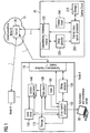
- a typical distributed network consists of N nodes, e.g, node 1,..node N, that are connected to a central clock 20 and to other destinations through a switch 30.
- the terms "global clock”, “master clock”, “central clock” are synonymous and well known in the art.
- Each one of the N nodes 1,..N has a local clock 150 that requires time synchronisation with the more precise central clock. In order for this to be achieved, each node will communicate with the central clock via the switch 30.
- the central clock is connected to the switch through a dedicated link thus ensuring that only a small amount of traffic is carried on this link.
- Each node comprises of a clock synchronisation processor 100 which executes the procedure from the side of the node, storage means 110 for storing the different time values necessary for performing the synchronisation procedure, a delay detector 120 for detecting whether synchronisation messages transmitted during the synchronisation procedure experience delays, a calculator 130 for performing the necessary calculations in the procedure, an update processor 140 for updating the local clock with the necessary values in order to synchronise the time on the local clock with that of the central clock 20, a local clock 150, a timer 160 for generating a random time to be used when the back-off procedure is performed, and transmission means/interface 170 for transmitting and receiving synchronisation messages.
- a clock synchronisation processor 100 which executes the procedure from the side of the node
- storage means 110 for storing the different time values necessary for performing the synchronisation procedure
- a delay detector 120 for detecting whether synchronisation messages transmitted during the synchronisation procedure experience delays
- a calculator 130 for performing the necessary calculations in the procedure
- an update processor 140 for updating the local clock with
- the central clock 20 also shown in fig.1 , comprises of a central clock synchronisation processor 200 which executes the procedure from the side of the central clock, storage means 210 for storing the different time values necessary for performing the synchronisation procedure, a delay detector 220 for detecting whether synchronisation messages transmitted during the synchronisation procedure experience delays, transmission means/interface 230 for transmitting and receiving synchronisation messages and a central clock 240 for providing a central time to each node.
- the transfer time of a message over a link can be decomposed into the following components: W + T + D.
- W is the waiting time before the transmission of the message begins.
- T is the transmission time of the message, and is proportional to the length of the message and the transmission rate of the link.
- D is the transmission delay, and is proportional to the length of the link and to the speed of the electromagnetic waves on the link.
- W can be further decomposed into the following components: Waiting time until the end of the transmission of the message that is currently being transmitted on the link + Transmission time of all messages of the same or higher priority that arrived at an earlier time + Transmission time of all messages of higher priority that arrive during the waiting time W.
- RTT W i up + W c down + W c up + W i down + T i up + T c down + T c up + T i down + D i up + D c down + D c up + S i - to - c + S i - to - i - i
- S i -to-c and S c-to- i give the switching delays within the switch.
- the invention also ensures that the sum of all T in the equation is constant and that each direction contributes half of the sum by defining that all messages sent from a node to the clock and all messages sent from the clock to a node have the same equal length, and also by ensuring that the transmission rate of the links is the same in both directions (though it may be different on different links).
- the message can be defined to have a maximum length Lmax, depending now on the coding used, if the message after coding is shorter in length to Lmax then filling bits are added. An alternative to this is to create a dummy parameter which is added to all messages that are smaller to Lmax. The same transmission rate is ensured by selecting symmetric transmission technologies.
- the inventive aspect of the invention exploits the fact that by monitoring a link, the monitoring instance such as a node or the central clock, can identify transmissions which did not experience any waiting time W before transmission. Therefore the following rule can be applied: Any transmission that is preceded by an idle state of the link did not experience any waiting time W.
- Each node (node 1,..node N) in the network and the central clock 20 both monitor their respective links in both directions and identify transmissions that did not experience any waiting time before being transmitted on the particular link they are monitoring.
- the central clock 20 will transmit to a node an additional synchronisation message W-INFO that contains information relating to the time-delay that the node's time synchronisation request and the reply back to it experienced at the central clock 20. This is done for each individual node.
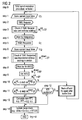
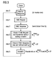
- Figures 2 and 3 show the corresponding algorithm of the time synchronisation protocol at a node and at the central clock. The procedure triggering the launching of the protocol is triggered by each node at regular intervals in order to keep their respective local clock synchronised with the central clock.
- a notification message such as an alarm, is triggered and sent to an operations and maintenance centre 50 to notify that a change in the network configuration has occurred.
- each node monitors its respective link for transmissions that did not experience a delay in the following way.
- Additional measures can be taken to control the probability of (1) and (2) occurring. These are:
- step 0 of fig. 2 the time synchronisation procedure is triggered, this will ensure that in step 1 the time synchronisation procedure will check the local clock time and store the current local time LT1 value in memory.
- a node will send a time synchronisation request message to the central clock.
- the procedure will cause the node to wait for a response to the message sent in step 2.
- step 5 the node will receive a time response reply message from the central clock which will contain the global time G T value from the central clock and will then stored it.
- step 6 the node will further store the local time value LT2 at the instant of reception of the time response message sent by the central clock (step 5).
- step 8 the procedure will cause the node to wait for the central clock to send information W-INFO regarding any delays caused on the link between the central clock and the switch W c up , W c down .
- step 9 the node receives this information and stores it in memory. Once the information has been received and stored, the procedure will perform a check, in step 10, to verify whether W i up and W c down are both equal to zero.
- step 11 If the result is negative N a back-off timer mechanism is triggered and the procedure returns to step 1. If the result is positive Y the procedure will go onto step 11, where another check is performed to verify whether W c up and W i down are both equal to zero. If the result is positive Y the procedure will go onto step 13 where the new RTT is calculated LT2- LT1 and the value stored in memory. In step 14 the procedure will then update the local clock modifying the local time based on the result of the calculation G T - (LT1+ RTT/2). Once the local clock has been updated the procedure will end, and it will return to step 0 until it is triggered to restart. If in step 11, the result is negative N the procedure will go onto step 12, where a check is performed to verify whether a RTT value is available. If such a value is not available then a back-off timer mechanism is triggered and the procedure returns to step 1. If such a value is available then the procedure will go onto step 14 in order to update the local clock.
- step 0 of fig. 3 the central clock monitors its link to the switch and waits for a time synchronisation request message to be received.
- step 1 a time synchronisation request message is received. This will cause the procedure to go onto step 2, whereby a time response reply message from the central clock which will contain the global time G T value from the central clock will be sent back to the node that requested it.
- the length of the time response reply message is equal to the length of the time synchronisation request message received in step 1.
- step 5 the central clock will transmit this information W c down , W c up to the node that requested the time synchronisation. The procedure will then return to step 0.
Landscapes
- Engineering & Computer Science (AREA)
- Computer Networks & Wireless Communication (AREA)
- Signal Processing (AREA)
- Data Exchanges In Wide-Area Networks (AREA)
- Mobile Radio Communication Systems (AREA)
- Small-Scale Networks (AREA)
- Synchronisation In Digital Transmission Systems (AREA)
Claims (14)
- Verfahren zur Zeitgebersynchronisation in einem Kommunikationsnetz (10) zwischen einer zentralen Zeitgebereinrichtung (20) mit einem zentralen Zeitgeber (240) und mindestens einem Knoten (Knoten 1, ... Knoten N) mit einem lokalen Zeitgeber (150), mit den folgenden Schritten:• Austauschen von Synchronisationsnachrichten zwischen dem mindestens einen Knoten (Knoten 1, ... Knoten N) und der zentralen Zeitgebereinrichtung (20), wobei in dem mindestens einen Knoten (Knoten 1, ... Knoten N) eine erste lokale Zeit (LT1) bestimmt wird, die der Zeit des Sendens einer ersten Synchronisationsnachricht entspricht, und in dem mindestens einen Knoten (Knoten 1, ... Knoten N) eine zweite lokale Zeit (LT2) bestimmt wird, die einer Zeit des Empfangs einer zweiten Synchronisationsnachricht entspricht, wobei die zweite Synchronisationsnachricht eine Zeitansprech-Antwortnachricht ist, wobei die zweite Synchronisationsnachricht Informationen bezüglich einer Zentralzeitgeberzeit (GT) in der zentralen Zeitgebereinrichtung (20) umfaßt;• in dem mindestens einen Knoten (Knoten 1, ... Knoten N) Bestimmen, ob die Synchronisationsnachrichten während des Synchronisationsnachrichtenaustauschs eine Wartezeitverzögerung erfahren haben;• in dem mindestens einen Knoten (Knoten 1, ... Knoten N) Berechnen einer vergangenen Zeit zwischen der ersten lokalen Zeit (LT1) und der zweiten lokalen Zeit (LT2) und ferner Verwenden der vergangenen Zeit bei der Berechnung einer Differenz zwischen dem lokalen Zeitgeber (150) des mindestens einen Knotens (Knoten 1, ... Knoten N) und dem zentralen Zeitgeber (240) in dem mindestens einen Knoten;gekennzeichnet durch• Aktualisieren des lokalen Zeitgebers (150) in dem mindestens einen Knoten (Knoten 1, ... Knoten N) durch Addieren der berechneten Zeitdifferenz zu der aktuellen Zeit des lokalen Zeitgebers (150), wenn die Bestimmung bestimmt, daß die Synchronisationsnachrichten frei von Wartezeitverzögerungen sind.
- Verfahren nach Anspruch 1, wobei die gesendeten Synchronisationsnachrichten eine identische Länge und eine identische Datenrate aufweisen.
- Verfahren nach Anspruch 1, wobei der mindestens eine Knoten (Knoten 1, ... Knoten N) auf die Bestimmung der Verzögerung bei der Übertragung einer ersten Synchronisationsnachricht zu der zentralen Zeitgebereinrichtung (20) hin eine erste Verzögerung (Wiup) bestimmt und auf die Bestimmung der Verzögerung bei der Übertragung der zweiten Synchronisationsnachricht, die die Zentralzeitgeberzeit (GT) enthält, hin eine zweite Verzögerung (Widown) bestimmt.
- Verfahren nach Anspruch 1 oder 3, ferner mit dem Schritt, daß die zentrale Zeitgebereinrichtung (20) auf die Bestimmung einer Verzögerung bei der Übertragung einer ersten Synchronisationsnachricht von dem mindestens einen Knoten (Knoten 1, ... Knoten N) hin eine dritte Verzögerung (Wcdown) bestimmt und auf die Bestimmung einer Verzögerung bei der Übertragung der zweiten Synchronisationsnachricht, die die Informationen bezüglich einer Zentralzeitgeberzeit (GT) enthält, hin eine vierte Verzögerung (Wcup) bestimmt und die dritte und vierte Verzögerung (Wcdown, Wcup) über eine weitere Synchronisationsnachricht (W-INFO) zu dem mindestens einen Knoten (Knoten 1, ... Knoten N) sendet.
- Verfahren nach einem der Ansprüche 3 bis 4, wobei der mindestens eine Knoten (Knoten 1, ... Knoten N) ferner bestimmt, ob die bestimmten Verzögerungen (Wiup, Widown, Wcdown, Wcup) gleich null sind und auf die Bestimmung hin, daß die bestimmten Verzögerungen (Wiup, Widown, Wcdown, Wcup) gleich null sind, den lokalen Zeitgeber (150) aktualisiert.
- Verfahren nach Anspruch 5, wobei der mindestens eine Knoten (Knoten 1, ... Knoten N) auf die Bestimmung hin, daß die erste und dritte Verzögerung (Wiup, Wcdown) nicht gleich null sind, die Zeitgebersynchronisation beendet und die Zeitgebersynchronisation zu einem späteren Zeitpunkt unter Verwendung eines zufallserzeugten Backoff-Timers (160) neustartet, um die spätere Zeit zu erzeugen.
- Verfahren nach Anspruch 5, wobei der mindestens eine Knoten (Knoten 1, ... Knoten N) auf die Bestimmung hin, daß die erste und dritte Verzögerung (Wiup, Wcdown) gleich null sind und daß die zweite und vierte Verzögerung (Widown, Wcup) nicht gleich null sind, aus einer vorherigen Zeitgebersynchronisation verifiziert, ob die vergangene Zeit existiert.
- Verfahren nach Anspruch 7, wobei der mindestens eine Knoten (Knoten 1, ... Knoten N) auf das Verifizieren hin, daß die vergangene Zeit existiert, diesen Wert bei der Berechnung der Differenz in dem Schritt des Aktualisierens des lokalen Zeitgebers (150) in dem mindestens einen Knoten (Knoten 1, ... Knoten N) verwendet und auf das Verifizieren hin, daß die vergangene Zeit nicht existiert, die Zeitgebersynchronisation beendet und die Zeitgebersynchronisation zu einem späteren Zeitpunkt unter Verwendung eines zufallserzeugten Backup-Timers (160) neustartet, um die spätere Zeit zu erzeugen.
- Verfahren nach Anspruch 1, wobei der Schritt des Aktualisierens des lokalen Zeitgebers (150) in dem mindestens einen Knoten (Knoten 1, ... Knoten N) ferner einen Schritt umfaßt, die vergangene Zeit mit einer zuvor berechneten vergangenen Zeit zu vergleichen und bei Detektion einer Varianz zwischen den beiden vergangenen Zeiten einen Alarm einer Netzverwaltungszentrale (50) zu senden.
- System in einem Kommunikationsnetz (10) mit einer zentralen Zeitgebereinrichtung (20) mit einem zentralen Zeitgeber (240) und mindestens einem Knoten (Knoten 1, ... Knoten N) mit einem lokalen Zeitgeber (150), umfassend:- Zeitgebersynchronisationsprozessoren (100, 200), die dafür ausgelegt sind, Synchronisationsnachrichten zwischen dem mindestens einen Knoten (Knoten 1, ... Knoten N) und der zentralen Zeitgebereinrichtung (20) auszutauschen, wobei der Zeitgebersynchronisationsprozessor (100) auf dem mindestens einen Knoten (Knoten 1, ... Knoten N) ferner dafür ausgelegt ist, eine erste lokale Zeit (LT1) zu bestimmen, die einer Zeit des Sendens einer ersten Synchronisationsnachricht entspricht, wobei die erste Synchronisationsnachricht eine Zeitsynchronisationsanforderungsnachricht ist, und eine zweite lokale Zeit (LT2) zu bestimmen, die einer Zeit des Empfangens einer zweiten Synchronisationsnachricht entspricht, wobei die zweite Synchronisationsnachricht eine Zeitansprech-Antwortnachricht ist, wobei die zweite Synchronisationsnachricht Informationen bezüglich einer Zentralzeitgeberzeit (GT) in der zentralen Zeitgebereinrichtung (20) umfaßt;- Detektionsmittel (120), die dafür ausgelegt sind, zu bestimmen, ob die Synchronisationsnachrichten während des Synchronisationsnachrichtenaustauschs eine Wartezeitverzögerung erfahren haben;- Berechnungsmittel (130), die sich auf dem mindestens einen Knoten (Knoten 1, ... Knoten N) befinden und dafür ausgelegt sind, eine vergangene Zeit zwischen der ersten lokalen Zeit (LT1) und der zweiten lokalen Zeit (LT2) zu berechnen und bei der Durchführung der Berechnung dafür ausgelegt sind, die vergangene Zeit in Speichermitteln (110) zu speichern, wobei die Berechnungsmittel (130) ferner dafür ausgelegt sind, die gespeicherte vergangene Zeit bei der Berechnung einer Differenz zwischen dem lokalen Zeitgeber (150) des mindestens einen Knotens (Knoten 1, ... Knoten N) und dem zentralen Zeitgeber (240) zu verwenden;- Aktualisierungsmittel (140), die sich auf dem mindestens einen Knoten (Knoten 1, ... Knoten N) befinden und dafür ausgelegt sind, den lokalen Zeitgeber (150) zu aktualisieren, indem die berechnete Differenz zu der aktuellen Zeit des lokalen Zeitgebers (150) addiert wird,dadurch gekennzeichnet, daß die Aktualisierungsmittel (140) den lokalen Zeitgeber aktualisieren, wenn die Detektionsmittel (120) bestimmen, daß die Synchronisationsnachrichten frei von Wartezeitverzögerung sind.
- System nach Anspruch 10, wobei die Detektionsmittel (120) ferner dafür ausgelegt sind, eine erste Verzögerung (Wiup) zu bestimmen, wenn eine Verzögerung bei der Übertragung einer ersten Synchronisationsnachricht zu der zentralen Zeitgebereinrichtung (20) bestimmt wird, und eine zweite Verzögerung (Widown) zu bestimmen, wenn eine Verzögerung bei der Übertragung der zweiten Synchronisationsnachricht, die Informationen bezüglich der Zentralzeitgeberzeit (GT) enthält, bestimmt wird.
- System nach Anspruch 10 oder 11, wobei die Detektionsmittel (120), die sich auf der zentralen Zeitgebereinrichtung (20) befinden, dafür ausgelegt sind, eine dritte Verzögerung (Wcdown) zu bestimmen, wenn eine Verzögerung bei der Übertragung der ersten Synchronisationsnachricht von dem mindestens einen Knoten (Knoten 1, ... Knoten N) bestimmt wird, und eine vierte Verzögerung (Wcup) zu bestimmen, wenn eine Verzögerung bei der Übertragung der Synchronisationsnachricht, die Informationen bezüglich der Zentralzeitgeberzeit (GT) enthält, bestimmt wird, und wobei Übertragungsmittel (230), die sich auf der zentralen Zeitgebereinrichtung (20) befinden, dafür ausgelegt sind, die dritte und vierte Verzögerung (Wcdown, Wcup) über eine weitere Synchronisationsnachricht (W-INFO) zu dem mindestens einen Knoten (Knoten 1, ... Knoten N) zu senden.
- System nach einem der Ansprüche 10 bis 12, wobei die Detektionsmittel (120), die sich in dem mindestens einen Knoten (Knoten 1, ... Knoten N) befinden, ferner dafür ausgelegt sind, zu bestimmen, ob die bestimmten Verzögerungen (Wiup, Widown, Wcdown, Wcup) gleich null sind, und auf eine Bestimmung hin, daß die Verzögerungen gleich null sind, ferner dafür ausgelegt sind, einen in dem mindestens einen Knoten (Knoten 1, ... Knoten N) befindlichen Zeitgebersynchronisationsprozessor (100) zu benachrichtigen, wobei der Zeitgebersynchronisationsprozessor (100) dafür ausgelegt ist, einen Aktualisierungsprozessor (140) zu benachrichtigen, um den lokalen Zeitgeber (150) zu aktualisieren.
- Knoten (Knoten 1, ... Knoten N) mit einem lokalen Zeitgeber (150) in einem Kommunikationsnetz (10), umfassend:- einen Zeitgebersynchronisationsprozessor (100), der dafür ausgelegt ist, Synchronisationsnachrichten zwischen dem Knoten (Knoten 1, ... Knoten N) und einer zentralen Zeitgebereinrichtung (20) mit einem zentralen Zeitgeber (240) auszutauschen, wobei der Zeitgebersynchronisationsprozessor (100) auf dem Knoten (Knoten 1, ... Knoten N) ferner dafür ausgelegt ist, eine erste lokale Zeit (LT1) zu bestimmen, die einer Zeit des Sendens einer ersten Synchronisationsnachricht entspricht, wobei die erste Synchronisationsnachricht eine Zeitsynchronisationsanforderungsnachricht ist, und eine zweite lokale Zeit (LT2) zu bestimmen, die einer Zeit des Empfangs einer zweiten Synchronisationsnachricht von der zentralen Zeitgebereinrichtung (20) entspricht, wobei die zweite Synchronisationsnachricht eine Zeitansprech-Antwortnachricht ist, wobei die zweite Synchronisationsnachricht Informationen bezüglich einer Zentralzeitgeberzeit (GT) in der zentralen Zeitgebereinrichtung (20) umfaßt;- Detektionsmittel (120), die dafür ausgelegt sind, zu bestimmen, ob die Synchronisationsnachrichten während des Synchronisationsnachrichtenaustauschs eine Wartezeitverzögerung erfahren haben;- Berechnungsmittel (130), die dafür ausgelegt sind, eine vergangene Zeit zwischen der ersten lokalen Zeit (LT1) und der zweiten lokalen Zeit (LT2) zu berechnen und auf die Durchführung der Berechnung hin dafür ausgelegt sind, die vergangene Zeit in Speichermitteln (110) zu speichern, wobei die Berechnungsmittel (130) ferner dafür ausgelegt sind, die gespeicherte vergangene Zeit bei der Berechnung einer Differenz zwischen dem lokalen Zeitgeber (150) und dem zentralen Zeitgeber (240) zu verwenden;- Aktualisierungsmittel (140), die dafür ausgelegt sind, den lokalen Zeitgeber (150) durch Addieren der berechneten Differenz zu der aktuellen Zeit des lokalen Zeitgebers (150) zu aktualisieren,dadurch gekennzeichnet, daß die Aktualisierungsmittel (140) den lokalen Zeitgeber aktualisieren, wenn die Detektionsmittel (120) bestimmen, daß die Synchronisationsnachrichten frei von Wartezeitverzögerung sind.
Priority Applications (4)
| Application Number | Priority Date | Filing Date | Title |
|---|---|---|---|
| EP04025575A EP1653643B1 (de) | 2004-10-27 | 2004-10-27 | Verfahren und Anlage zur Zeitsynchronisation in einem verteilten Kommunikationsnetzwerk |
| AT04025575T ATE389983T1 (de) | 2004-10-27 | 2004-10-27 | Verfahren und anlage zur zeitsynchronisation in einem verteilten kommunikationsnetzwerk |
| DE602004012571T DE602004012571D1 (de) | 2004-10-27 | 2004-10-27 | Verfahren und Anlage zur Zeitsynchronisation in einem verteilten Kommunikationsnetzwerk |
| US11/259,110 US20060109868A1 (en) | 2004-10-27 | 2005-10-27 | Method and system for time synchronisation in a distributed communications network |
Applications Claiming Priority (1)
| Application Number | Priority Date | Filing Date | Title |
|---|---|---|---|
| EP04025575A EP1653643B1 (de) | 2004-10-27 | 2004-10-27 | Verfahren und Anlage zur Zeitsynchronisation in einem verteilten Kommunikationsnetzwerk |
Publications (2)
| Publication Number | Publication Date |
|---|---|
| EP1653643A1 EP1653643A1 (de) | 2006-05-03 |
| EP1653643B1 true EP1653643B1 (de) | 2008-03-19 |
Family
ID=34927141
Family Applications (1)
| Application Number | Title | Priority Date | Filing Date |
|---|---|---|---|
| EP04025575A Expired - Lifetime EP1653643B1 (de) | 2004-10-27 | 2004-10-27 | Verfahren und Anlage zur Zeitsynchronisation in einem verteilten Kommunikationsnetzwerk |
Country Status (4)
| Country | Link |
|---|---|
| US (1) | US20060109868A1 (de) |
| EP (1) | EP1653643B1 (de) |
| AT (1) | ATE389983T1 (de) |
| DE (1) | DE602004012571D1 (de) |
Families Citing this family (6)
| Publication number | Priority date | Publication date | Assignee | Title |
|---|---|---|---|---|
| US8255732B2 (en) * | 2008-05-28 | 2012-08-28 | The United States Of America, As Represented By The Administrator Of The National Aeronautics And Space Administration | Self-stabilizing byzantine-fault-tolerant clock synchronization system and method |
| JP5449566B2 (ja) * | 2010-09-15 | 2014-03-19 | 三菱電機株式会社 | 通信装置および遅延検出方法 |
| EP2687938A3 (de) * | 2012-07-18 | 2018-01-03 | Intel Corporation | Messung der Zeitversätze zwischen Vorrichtungen mit unabhängigen Siliziumuhren |
| WO2014014520A1 (en) * | 2012-07-18 | 2014-01-23 | Intel Corporation | Measuring time offsets between devices with independent silicon clocks |
| DE102012216689B4 (de) * | 2012-09-18 | 2017-05-04 | Continental Automotive Gmbh | Verfahren zur Überwachung eines Ethernet-basierten Kommunikationsnetzwerks in einem Kraftfahrzeug |
| US10025344B2 (en) | 2015-04-21 | 2018-07-17 | The United States Of America As Represented By The Administrator Of Nasa | Self-stabilizing distributed symmetric-fault tolerant synchronization protocol |
Family Cites Families (9)
| Publication number | Priority date | Publication date | Assignee | Title |
|---|---|---|---|---|
| US5052029A (en) * | 1990-04-05 | 1991-09-24 | Apple Computer, Inc. | Self-correcting synchronization signal method and apparatus |
| US5790808A (en) * | 1995-07-06 | 1998-08-04 | 3 Com | Active topology maintenance in reconfiguring bridged local area networks with state transition with forgetting interval |
| US5790805A (en) * | 1996-04-23 | 1998-08-04 | Ncr Corporation | Distributed timer synchronization |
| US5878032A (en) * | 1997-11-07 | 1999-03-02 | Northern Telecom Limited | Delay monitoring of telecommunication networks |
| JP3358528B2 (ja) * | 1998-03-27 | 2002-12-24 | ヤマハ株式会社 | 通信装置及び通信方法 |
| NO313778B1 (no) * | 2000-06-06 | 2002-11-25 | Ontime Networks As | Fremgangsmåte for å sikre aksess til et transmisjonsmedium ved et forhåndsbestemt tidspunkt og en tidsserver som benytterfremgangsmåten |
| GB2373400B (en) * | 2001-01-17 | 2003-04-09 | Marconi Comm Ltd | Real time clocks in communications networks |
| DE10260807B4 (de) * | 2002-12-23 | 2007-07-05 | Siemens Ag | Sendeverfahren für eine Zeitreferenz über ein Übertragungsmedium und hiermit korrespondierender Zeitgeberblock |
| US7397825B2 (en) * | 2004-03-10 | 2008-07-08 | Scientific-Atlanta, Inc. | Transport stream dejitterer |
-
2004
- 2004-10-27 EP EP04025575A patent/EP1653643B1/de not_active Expired - Lifetime
- 2004-10-27 DE DE602004012571T patent/DE602004012571D1/de not_active Expired - Lifetime
- 2004-10-27 AT AT04025575T patent/ATE389983T1/de not_active IP Right Cessation
-
2005
- 2005-10-27 US US11/259,110 patent/US20060109868A1/en not_active Abandoned
Also Published As
| Publication number | Publication date |
|---|---|
| EP1653643A1 (de) | 2006-05-03 |
| ATE389983T1 (de) | 2008-04-15 |
| DE602004012571D1 (de) | 2008-04-30 |
| US20060109868A1 (en) | 2006-05-25 |
Similar Documents
| Publication | Publication Date | Title |
|---|---|---|
| EP3970322B1 (de) | Ratenoptimierte überlastungsverwaltung | |
| US6697382B1 (en) | Distributing and synchronizing a representation of time between components of a packet switching system | |
| Parsa et al. | Improving TCP congestion control over internets with heterogeneous transmission media | |
| CN102647270B (zh) | 航空电子设备网络中的自由运转节点的时间同步方法 | |
| US7457868B1 (en) | Methods and apparatus for measuring network performance | |
| US7103124B1 (en) | Synchronization of nodes | |
| EP2661048B1 (de) | Verarbeitungsverfahren and vorrichtung für mitgliedverbindung in einer mehrfachverbindungsgruppe | |
| US12250157B2 (en) | Network congestion control in sub-round trip time | |
| EP2451099B1 (de) | Verfahren und System für die optische Netzwerk-Smart-Timer-Verwaltung per Verzögerungsmessung zwischen Spannen | |
| US20100123572A1 (en) | Alarm reordering to handle alarm storms in large networks | |
| EP4149026B1 (de) | System und verfahren zur taktwiederherstellung in einem paketcomputernetzwerk | |
| WO2002019654A2 (en) | Method for improving tcp performance over wireless links | |
| CN110492967B (zh) | 一种时间同步方法、中继设备及装置 | |
| US12513076B2 (en) | Delay sensitive network estimation system | |
| CN109565344B (zh) | 用于确定传播延迟的系统与方法 | |
| US20140369218A1 (en) | Measurement on a data flow in a communication network | |
| EP1653643B1 (de) | Verfahren und Anlage zur Zeitsynchronisation in einem verteilten Kommunikationsnetzwerk | |
| JP4542027B2 (ja) | 時刻同期方法、時刻クライアント、時刻サーバ、アプリケーション装置及び時刻同期システム | |
| Jiang et al. | StarTCP: Handover-aware transport protocol for starlink | |
| KR20220099586A (ko) | 차량 네트워크 시스템에서 시간 동기화 스위치 및 그것의 동작 방법 | |
| KR101058998B1 (ko) | 전자식 계전계측기의 시각동기 장치 및 그 방법 | |
| KR20100048124A (ko) | 근거리 통신망에서의 시간 동기화 방법 | |
| Mills et al. | Highball: a high speed, reserved-access, wide area network | |
| CN109716683B (zh) | 实时内容分发系统中的时间同步 | |
| US20250023705A1 (en) | Clock synchronization between networked devices based on packet congestion information |
Legal Events
| Date | Code | Title | Description |
|---|---|---|---|
| PUAI | Public reference made under article 153(3) epc to a published international application that has entered the european phase |
Free format text: ORIGINAL CODE: 0009012 |
|
| AK | Designated contracting states |
Kind code of ref document: A1 Designated state(s): AT BE BG CH CY CZ DE DK EE ES FI FR GB GR HU IE IT LI LU MC NL PL PT RO SE SI SK TR |
|
| AX | Request for extension of the european patent |
Extension state: AL HR LT LV MK |
|
| 17P | Request for examination filed |
Effective date: 20060522 |
|
| 17Q | First examination report despatched |
Effective date: 20060620 |
|
| 17Q | First examination report despatched |
Effective date: 20060620 |
|
| AKX | Designation fees paid |
Designated state(s): AT BE BG CH CY CZ DE DK EE ES FI FR GB GR HU IE IT LI LU MC NL PL PT RO SE SI SK TR |
|
| RAP1 | Party data changed (applicant data changed or rights of an application transferred) |
Owner name: NOKIA SIEMENS NETWORKS GMBH & CO. KG |
|
| GRAP | Despatch of communication of intention to grant a patent |
Free format text: ORIGINAL CODE: EPIDOSNIGR1 |
|
| RAP3 | Party data changed (applicant data changed or rights of an application transferred) |
Owner name: NOKIA SIEMENS NETWORKS S.P.A. |
|
| RAP3 | Party data changed (applicant data changed or rights of an application transferred) |
Owner name: NOKIA SIEMENS NETWORKS GMBH & CO. KG |
|
| GRAS | Grant fee paid |
Free format text: ORIGINAL CODE: EPIDOSNIGR3 |
|
| GRAA | (expected) grant |
Free format text: ORIGINAL CODE: 0009210 |
|
| AK | Designated contracting states |
Kind code of ref document: B1 Designated state(s): AT BE BG CH CY CZ DE DK EE ES FI FR GB GR HU IE IT LI LU MC NL PL PT RO SE SI SK TR |
|
| REG | Reference to a national code |
Ref country code: GB Ref legal event code: FG4D |
|
| REG | Reference to a national code |
Ref country code: CH Ref legal event code: EP |
|
| REF | Corresponds to: |
Ref document number: 602004012571 Country of ref document: DE Date of ref document: 20080430 Kind code of ref document: P |
|
| REG | Reference to a national code |
Ref country code: IE Ref legal event code: FG4D |
|
| PG25 | Lapsed in a contracting state [announced via postgrant information from national office to epo] |
Ref country code: FI Free format text: LAPSE BECAUSE OF FAILURE TO SUBMIT A TRANSLATION OF THE DESCRIPTION OR TO PAY THE FEE WITHIN THE PRESCRIBED TIME-LIMIT Effective date: 20080319 |
|
| PG25 | Lapsed in a contracting state [announced via postgrant information from national office to epo] |
Ref country code: AT Free format text: LAPSE BECAUSE OF FAILURE TO SUBMIT A TRANSLATION OF THE DESCRIPTION OR TO PAY THE FEE WITHIN THE PRESCRIBED TIME-LIMIT Effective date: 20080319 |
|
| NLV1 | Nl: lapsed or annulled due to failure to fulfill the requirements of art. 29p and 29m of the patents act | ||
| PG25 | Lapsed in a contracting state [announced via postgrant information from national office to epo] |
Ref country code: PL Free format text: LAPSE BECAUSE OF FAILURE TO SUBMIT A TRANSLATION OF THE DESCRIPTION OR TO PAY THE FEE WITHIN THE PRESCRIBED TIME-LIMIT Effective date: 20080319 Ref country code: BE Free format text: LAPSE BECAUSE OF FAILURE TO SUBMIT A TRANSLATION OF THE DESCRIPTION OR TO PAY THE FEE WITHIN THE PRESCRIBED TIME-LIMIT Effective date: 20080319 Ref country code: SI Free format text: LAPSE BECAUSE OF FAILURE TO SUBMIT A TRANSLATION OF THE DESCRIPTION OR TO PAY THE FEE WITHIN THE PRESCRIBED TIME-LIMIT Effective date: 20080319 |
|
| PG25 | Lapsed in a contracting state [announced via postgrant information from national office to epo] |
Ref country code: CZ Free format text: LAPSE BECAUSE OF FAILURE TO SUBMIT A TRANSLATION OF THE DESCRIPTION OR TO PAY THE FEE WITHIN THE PRESCRIBED TIME-LIMIT Effective date: 20080319 Ref country code: ES Free format text: LAPSE BECAUSE OF FAILURE TO SUBMIT A TRANSLATION OF THE DESCRIPTION OR TO PAY THE FEE WITHIN THE PRESCRIBED TIME-LIMIT Effective date: 20080630 Ref country code: PT Free format text: LAPSE BECAUSE OF FAILURE TO SUBMIT A TRANSLATION OF THE DESCRIPTION OR TO PAY THE FEE WITHIN THE PRESCRIBED TIME-LIMIT Effective date: 20080826 Ref country code: SE Free format text: LAPSE BECAUSE OF FAILURE TO SUBMIT A TRANSLATION OF THE DESCRIPTION OR TO PAY THE FEE WITHIN THE PRESCRIBED TIME-LIMIT Effective date: 20080619 Ref country code: SK Free format text: LAPSE BECAUSE OF FAILURE TO SUBMIT A TRANSLATION OF THE DESCRIPTION OR TO PAY THE FEE WITHIN THE PRESCRIBED TIME-LIMIT Effective date: 20080319 |
|
| PG25 | Lapsed in a contracting state [announced via postgrant information from national office to epo] |
Ref country code: NL Free format text: LAPSE BECAUSE OF FAILURE TO SUBMIT A TRANSLATION OF THE DESCRIPTION OR TO PAY THE FEE WITHIN THE PRESCRIBED TIME-LIMIT Effective date: 20080319 Ref country code: RO Free format text: LAPSE BECAUSE OF FAILURE TO SUBMIT A TRANSLATION OF THE DESCRIPTION OR TO PAY THE FEE WITHIN THE PRESCRIBED TIME-LIMIT Effective date: 20080319 |
|
| EN | Fr: translation not filed | ||
| PLBE | No opposition filed within time limit |
Free format text: ORIGINAL CODE: 0009261 |
|
| STAA | Information on the status of an ep patent application or granted ep patent |
Free format text: STATUS: NO OPPOSITION FILED WITHIN TIME LIMIT |
|
| PG25 | Lapsed in a contracting state [announced via postgrant information from national office to epo] |
Ref country code: DE Free format text: LAPSE BECAUSE OF FAILURE TO SUBMIT A TRANSLATION OF THE DESCRIPTION OR TO PAY THE FEE WITHIN THE PRESCRIBED TIME-LIMIT Effective date: 20080620 Ref country code: DK Free format text: LAPSE BECAUSE OF FAILURE TO SUBMIT A TRANSLATION OF THE DESCRIPTION OR TO PAY THE FEE WITHIN THE PRESCRIBED TIME-LIMIT Effective date: 20080319 |
|
| 26N | No opposition filed |
Effective date: 20081222 |
|
| PG25 | Lapsed in a contracting state [announced via postgrant information from national office to epo] |
Ref country code: EE Free format text: LAPSE BECAUSE OF FAILURE TO SUBMIT A TRANSLATION OF THE DESCRIPTION OR TO PAY THE FEE WITHIN THE PRESCRIBED TIME-LIMIT Effective date: 20080319 Ref country code: BG Free format text: LAPSE BECAUSE OF FAILURE TO SUBMIT A TRANSLATION OF THE DESCRIPTION OR TO PAY THE FEE WITHIN THE PRESCRIBED TIME-LIMIT Effective date: 20080619 |
|
| PG25 | Lapsed in a contracting state [announced via postgrant information from national office to epo] |
Ref country code: MC Free format text: LAPSE BECAUSE OF NON-PAYMENT OF DUE FEES Effective date: 20081031 |
|
| REG | Reference to a national code |
Ref country code: CH Ref legal event code: PL |
|
| PGFP | Annual fee paid to national office [announced via postgrant information from national office to epo] |
Ref country code: GB Payment date: 20081021 Year of fee payment: 5 |
|
| PG25 | Lapsed in a contracting state [announced via postgrant information from national office to epo] |
Ref country code: IT Free format text: LAPSE BECAUSE OF FAILURE TO SUBMIT A TRANSLATION OF THE DESCRIPTION OR TO PAY THE FEE WITHIN THE PRESCRIBED TIME-LIMIT Effective date: 20080319 |
|
| PG25 | Lapsed in a contracting state [announced via postgrant information from national office to epo] |
Ref country code: CY Free format text: LAPSE BECAUSE OF FAILURE TO SUBMIT A TRANSLATION OF THE DESCRIPTION OR TO PAY THE FEE WITHIN THE PRESCRIBED TIME-LIMIT Effective date: 20080319 |
|
| PG25 | Lapsed in a contracting state [announced via postgrant information from national office to epo] |
Ref country code: CH Free format text: LAPSE BECAUSE OF NON-PAYMENT OF DUE FEES Effective date: 20081031 Ref country code: IE Free format text: LAPSE BECAUSE OF NON-PAYMENT OF DUE FEES Effective date: 20081028 Ref country code: LI Free format text: LAPSE BECAUSE OF NON-PAYMENT OF DUE FEES Effective date: 20081031 |
|
| PG25 | Lapsed in a contracting state [announced via postgrant information from national office to epo] |
Ref country code: LU Free format text: LAPSE BECAUSE OF NON-PAYMENT OF DUE FEES Effective date: 20081027 Ref country code: HU Free format text: LAPSE BECAUSE OF FAILURE TO SUBMIT A TRANSLATION OF THE DESCRIPTION OR TO PAY THE FEE WITHIN THE PRESCRIBED TIME-LIMIT Effective date: 20080920 |
|
| PG25 | Lapsed in a contracting state [announced via postgrant information from national office to epo] |
Ref country code: TR Free format text: LAPSE BECAUSE OF FAILURE TO SUBMIT A TRANSLATION OF THE DESCRIPTION OR TO PAY THE FEE WITHIN THE PRESCRIBED TIME-LIMIT Effective date: 20080319 |
|
| PG25 | Lapsed in a contracting state [announced via postgrant information from national office to epo] |
Ref country code: GR Free format text: LAPSE BECAUSE OF FAILURE TO SUBMIT A TRANSLATION OF THE DESCRIPTION OR TO PAY THE FEE WITHIN THE PRESCRIBED TIME-LIMIT Effective date: 20080620 |
|
| PG25 | Lapsed in a contracting state [announced via postgrant information from national office to epo] |
Ref country code: GB Free format text: LAPSE BECAUSE OF NON-PAYMENT OF DUE FEES Effective date: 20091027 |
|
| PG25 | Lapsed in a contracting state [announced via postgrant information from national office to epo] |
Ref country code: FR Free format text: LAPSE BECAUSE OF FAILURE TO SUBMIT A TRANSLATION OF THE DESCRIPTION OR TO PAY THE FEE WITHIN THE PRESCRIBED TIME-LIMIT Effective date: 20090109 |