EP1653595A1 - Motor generator and electric vehicle having the same - Google Patents
Motor generator and electric vehicle having the same Download PDFInfo
- Publication number
- EP1653595A1 EP1653595A1 EP04745502A EP04745502A EP1653595A1 EP 1653595 A1 EP1653595 A1 EP 1653595A1 EP 04745502 A EP04745502 A EP 04745502A EP 04745502 A EP04745502 A EP 04745502A EP 1653595 A1 EP1653595 A1 EP 1653595A1
- Authority
- EP
- European Patent Office
- Prior art keywords
- rotor
- rotational shaft
- stator
- electrical machine
- rotary electrical
- Prior art date
- Legal status (The legal status is an assumption and is not a legal conclusion. Google has not performed a legal analysis and makes no representation as to the accuracy of the status listed.)
- Withdrawn
Links
Images



Classifications
-
- H—ELECTRICITY
- H02—GENERATION; CONVERSION OR DISTRIBUTION OF ELECTRIC POWER
- H02K—DYNAMO-ELECTRIC MACHINES
- H02K21/00—Synchronous motors having permanent magnets; Synchronous generators having permanent magnets
- H02K21/02—Details
- H02K21/021—Means for mechanical adjustment of the excitation flux
- H02K21/022—Means for mechanical adjustment of the excitation flux by modifying the relative position between field and armature, e.g. between rotor and stator
- H02K21/025—Means for mechanical adjustment of the excitation flux by modifying the relative position between field and armature, e.g. between rotor and stator by varying the thickness of the air gap between field and armature
- H02K21/026—Axial air gap machines
-
- H—ELECTRICITY
- H02—GENERATION; CONVERSION OR DISTRIBUTION OF ELECTRIC POWER
- H02K—DYNAMO-ELECTRIC MACHINES
- H02K7/00—Arrangements for handling mechanical energy structurally associated with dynamo-electric machines, e.g. structural association with mechanical driving motors or auxiliary dynamo-electric machines
- H02K7/10—Structural association with clutches, brakes, gears, pulleys or mechanical starters
- H02K7/116—Structural association with clutches, brakes, gears, pulleys or mechanical starters with gears
-
- B—PERFORMING OPERATIONS; TRANSPORTING
- B62—LAND VEHICLES FOR TRAVELLING OTHERWISE THAN ON RAILS
- B62K—CYCLES; CYCLE FRAMES; CYCLE STEERING DEVICES; RIDER-OPERATED TERMINAL CONTROLS SPECIALLY ADAPTED FOR CYCLES; CYCLE AXLE SUSPENSIONS; CYCLE SIDECARS, FORECARS, OR THE LIKE
- B62K2204/00—Adaptations for driving cycles by electric motor
-
- H—ELECTRICITY
- H02—GENERATION; CONVERSION OR DISTRIBUTION OF ELECTRIC POWER
- H02K—DYNAMO-ELECTRIC MACHINES
- H02K21/00—Synchronous motors having permanent magnets; Synchronous generators having permanent magnets
- H02K21/12—Synchronous motors having permanent magnets; Synchronous generators having permanent magnets with stationary armatures and rotating magnets
- H02K21/14—Synchronous motors having permanent magnets; Synchronous generators having permanent magnets with stationary armatures and rotating magnets with magnets rotating within the armatures
- H02K21/16—Synchronous motors having permanent magnets; Synchronous generators having permanent magnets with stationary armatures and rotating magnets with magnets rotating within the armatures having annular armature cores with salient poles
-
- H—ELECTRICITY
- H02—GENERATION; CONVERSION OR DISTRIBUTION OF ELECTRIC POWER
- H02K—DYNAMO-ELECTRIC MACHINES
- H02K21/00—Synchronous motors having permanent magnets; Synchronous generators having permanent magnets
- H02K21/12—Synchronous motors having permanent magnets; Synchronous generators having permanent magnets with stationary armatures and rotating magnets
- H02K21/24—Synchronous motors having permanent magnets; Synchronous generators having permanent magnets with stationary armatures and rotating magnets with magnets axially facing the armatures, e.g. hub-type cycle dynamos
-
- Y—GENERAL TAGGING OF NEW TECHNOLOGICAL DEVELOPMENTS; GENERAL TAGGING OF CROSS-SECTIONAL TECHNOLOGIES SPANNING OVER SEVERAL SECTIONS OF THE IPC; TECHNICAL SUBJECTS COVERED BY FORMER USPC CROSS-REFERENCE ART COLLECTIONS [XRACs] AND DIGESTS
- Y02—TECHNOLOGIES OR APPLICATIONS FOR MITIGATION OR ADAPTATION AGAINST CLIMATE CHANGE
- Y02T—CLIMATE CHANGE MITIGATION TECHNOLOGIES RELATED TO TRANSPORTATION
- Y02T10/00—Road transport of goods or passengers
- Y02T10/60—Other road transportation technologies with climate change mitigation effect
- Y02T10/64—Electric machine technologies in electromobility
Definitions
- the present invention relates to a rotary electrical machine and an electric vehicle having such rotary electrical machine.
- a rotary electrical machine having a rotor, a rotational shaft attached to the rotor, and a stator, and controlling the strength of the field magnet established between the rotor and the stator in response to a rotational speed of the rotor.
- the strength of the field magnet by controlling the strength of the field magnet, the characteristic of the rotary electrical machine (such as, for example, a relationship between the rotational speed and the output torque of the rotational shaft) can be adjusted.
- This rotary electrical machine includes a housing which is a stationary side member and forms an outer shell of the rotary electrical machine, a rotational shaft journaled on the housing for rotation about an axis thereof, but not for movement in the axial direction thereof, a rotor coupled with the rotational shaft to rotate about the axis together with the rotational shaft, a stator supported by the housing so as to face the rotor, and a centrifugal governor joined to a distal end of the rotational shaft.
- a yoke which forms the stator has multiple receiving apertures that extends parallel to the axial direction of the rotational shaft (can be simply described as "extending in the axial direction” below).
- Each auxiliary yoke which extends in the axial direction of the rotational shaft is inserted into a corresponding receiving aperture.
- Each auxiliary yoke is connected to the centrifugal governor.
- the centrifugal governor moves the associated auxiliary yoke in the axial direction. That is, an inserted length of each auxiliary yoke is variable in accordance with the rotational speed of the rotational shaft.
- the reluctance of the yoke varies in response to the rotational speed of the rotational shaft, and the strength of the field magnet established between the rotor and the stator can be adjusted.
- the rotational shaft When the rotary electrical machine operates as an electric motor, an electric current is supplied to the stator so that the rotor rotates. With the rotation of the rotor, the rotational shaft generates output torque.
- the field magnet if the rotational shaft makes a high speed rotation, the field magnet is weaken because of an action of the centrifugal governor. As a result, the output torque per unit current (i.e., output torque of the rotational shaft generated per unit current flowing through the stator) becomes small. As thus discussed, by weakening the field magnet, the rotational shaft can rotate at a high speed under a low torque condition.
- the field magnet can be strengthened by the action of the centrifugal governor operating in association with the rotational shaft. As a result, the output torque per unit current becomes large. Thus, by strengthening the field magnet, the rotational shaft can rotate at a low speed under a high torque condition.
- JP-A-Hei03-215154 discloses a rotary electrical machine in which the strength of the field magnet between a rotor and a stator is adjusted by making the rotor approach or recede from the stator.
- This rotary electrical machine includes a stationary side member, a rotational shaft journaled on the stationary side member for rotation about an axis thereof, the rotor coupled with the rotational shaft to rotate about the axis, the stator supported by the stationary side member so as to face the rotor, a spring urging the rotational shaft in a direction in which the rotor recedes from the stator, and an electromagnet electrically connected to the stator in series.
- the rotational shaft is formed of a magnetic material.
- the electromagnet In this rotary electrical machine, when an electric current is supplied to the electromagnet, the electromagnet attracts the rotational shaft in the axial direction. If the attractive force of the electromagnet is larger than the urging force of the spring, the rotor approaches the stator. Conversely, the attractive force of the electromagnet is smaller than the urging force of the spring, the rotor recedes from the stator. As thus discussed, the electromagnet and the spring together form an actuator that moves the rotational shaft in the axial direction.
- the rotary electrical machine described above When the rotary electrical machine described above operates as an electric motor, an electric current is supplied to the stator and the electromagnet to rotate the rotor. If the load applied to the rotational shaft is small, the current supplied to the stator is small. Thus, the current supplied to the electromagnet is also small, and the electromagnetic force of the electromagnet is small. Accordingly, the force of the electromagnet that attracts the rotational shaft is smaller than the urging force of the spring, and the rotor is kept separate from the stator. Consequently, the gap size between the rotor and the stator is large to keep the field magnet weak.
- the same torque characteristic as that of the rotary electrical machine disclosed in Patent Document 1 can be obtained. That is, also according to the rotary electrical machine disclosed in Patent Document 2, when it operates as an electric motor, the torque characteristic can be obtained in which the rotational speed is high while the output torque of the rotational shaft is small, and also the output torque is large while the rotational speed is low.
- the rotary electrical machine disclosed in Patent Document 1 needs a centrifugal governor attached to the rotational shaft to obtain the torque characteristic discussed above.
- the centrifugal governor generates the centrifugal force using a weight
- the governor needs some structure that moves the weight in a radial direction of the rotor.
- the rotary electrical machine needs to have a certain capacity in the radial direction. Accordingly arises a problem such that the external size of the rotary electrical machine having the centrifugal governor is inevitably large.
- the receiving apertures, the auxiliary yokes and the like described above are necessary in addition to the centrifugal governor, another problem arises such that the structure of the rotary electrical machine is complicated.
- the rotary electrical machine disclosed in Patent Document 2 needs to have the above-described actuator provided outside of the rotational shaft in the axial direction.
- the length of the rotary electrical machine in the axial direction can be longer correspondingly to the length of the actuator.
- the size of the rotary electrical machine is inevitably large. A large space thus is necessary for placing the rotary electrical machine.
- the present invention is made under the circumstances described above, and an object thereof is to downsize external dimensions of a rotary electrical machine, and also to simplifies a structure of the machine, in which a rotor is moved in an axial direction thereof to make the rotor approach or recede from a stator, thereby the strength of the field magnet established between the rotor and the stator is controllable.
- Another object of the present invention is, in the rotary electrical machine, to make the rotor movable in the axial direction without inviting the upsizing of the external dimensions or making the structure complicated.
- a rotary electrical machine includes a base member; a stator fixed to the base member; a rotational shaft supported by the base member for rotation; a rotor coupled with the rotational shaft and facing the stator to mutually transmit torque with the rotational shaft therebetween; and a rotor position changing mechanism for making the rotor approach the stator or for making the rotor recede from the stator along an axial direction of the rotational shaft in response to the magnitude of the transmission torque between the rotational shaft and the rotor.
- the rotary electrical machine described above When the rotary electrical machine described above operates as an electric motor, the torque is transmitted to the rotational shaft from the rotor to drive the rotational shaft. On the other hand, when the rotary electrical machine operates as a generator, the torque is transmitted to the rotor from the rotational shaft to drive the rotor. Thus, under the operational condition of the rotary electrical machine, the torque is transmitted between the rotational shaft and the rotor. Additionally, the rotary electrical machine is not limited to such a machine operating as either the electric motor or the generator. It can be a machine that operates only as the electric motor or as the generator.
- the rotary electrical machine has the rotor position changing mechanism, the rotor approaches or recedes from the stator in response to the magnitude of the transmission torque between the rotational shaft and the rotor.
- the field magnet established between the rotor and the stator becomes strong while the rotor approaches the stator, and, conversely, it becomes weak while the rotor recedes from the stator.
- the strength of the rotary electrical machine is controlled in response to the magnitude of the transmission torque between the rotational shaft and the rotor.
- the relationship between the rotational speed and the torque of the rotational shaft i.e., the torque characteristic varies.
- the torque characteristic of the rotary electrical machine can be desirably changed.
- the torque characteristic can be realized in which, when the rotary electrical machine operates as the electric motor, the output torque is large while the rotational speed is in a low speed range, and the output torque is small while the rotational speed is in a high speed range.
- the rotary electrical machine can operate in a wide operational range.
- the rotary electrical machine differently from the rotary electrical machine of Patent Document 1, no centrifugal governor, which external size is large and which structure is complicated, is not required. Accordingly, the external dimensions of the rotary electrical machine can be downsized. Also, the structure of the rotary electrical machine can be simplified. By applying this rotary electrical machine to an electric vehicle, the downsizing and the simplification of the structure can be achieved for the electric vehicle.
- the rotor position changing mechanism includes a force component generating mechanism for generating a force component that moves the rotor in the axial direction of the rotational shaft, from the transmission torque transmitted between the rotational shaft and the rotor.
- Another rotary electrical machine includes a base member; a stator fixed to the base member; a rotational shaft supported by the base member for rotation; a rotor coupled with the rotational shaft and facing the stator to mutually transmit torque with the rotational shaft therebetween; and a rotor position changing mechanism for making the rotor approach the stator or for making the rotor recede from the stator using a portion of the transmission torque transmitted between the rotational shaft and the rotor as driving force.
- the rotor position changing mechanism can make the rotor approach the stator when the transmission torque transmitted to the rotational shaft from the rotor increases.
- the rotary electrical machine when the rotary electrical machine operates as the electric motor, if the torque transmitted to the rotational shaft from the rotor increases, the rotor approaches the stator, and the field magnet between the rotor and the stator becomes strong. Thus, under the condition that the load applied to the rotational shaft is large, the output torque of the rotational shaft can be large. Therefore, for example, if the rotary electrical machine is used as a driving force source of an electric vehicle for running, the output torque of the electric vehicle in a starting operation or in an accelerating operation can be large. Quick start or acceleration can be realized.
- the rotor position changing mechanism can make the rotor recede from the stator when the transmission torque transmitted to the rotational shaft from the rotor decreases.
- the rotary electrical machine when the rotary electrical machine operates as the electric motor, if the torque transmitted to the rotational shaft from the rotor decreases, then the rotor recedes from the stator, and the field magnet between the rotor and the stator becomes weak.
- the rotational shaft under the condition that the load applied to the rotational shaft is small, the rotational shaft can rotate at a high speed.
- the running speed of the vehicle under the condition that the output torque is small i.e., under a low torque condition, can be high.
- the rotor position changing mechanism can make the rotor recede from the stator when the transmission torque transmitted to the rotor from the rotational shaft increases.
- the rotor when the rotor has moved to a desired position, if the force by which the rotor position changing mechanism forces the rotor to recede from the stator and the attractive magnetic force generated between the rotor and the stator balance with each other, the rotor can be placed at a desired position regardless of the rotational speed of the rotational shaft. That is, the voltage generated by the rotary electrical machine can be nearly fixed.
- the generating characteristic of the rotary electrical machine (or the braking characteristic thereof when the regenerating braking is made) can be freely set. If the generated voltage is charged into a secondary battery, generating circuits such as, for example, a voltage rising circuit or a voltage lowering circuit can be simplified. Also, the characteristic of the rotary electrical machine can be adjusted so as to be suitable for charging.
- the rotor position changing mechanism has a spring urging the rotor to a direction in which the rotor approaches the stator or to a direction in which the rotor recedes from the stator.
- the characteristic of the spring by adjusting the characteristic of the spring, the degree of the approaching state or the receding state between the rotor and the stator can be freely set. Accordingly, by adjusting the characteristic of the spring, the torque characteristic of the rotary electrical machine can be adjusted. Because it is easy to adjust the characteristic of the spring, the torque characteristic of the rotary electrical machine can be easily adjusted. Also, because the spring has a simple structure, the adjustment of the torque characteristic can be realized by such a simple structure.
- the spring includes a first spring member urging the rotor to the direction in which the rotor approaches the stator, and a second spring member urging the rotor to the direction in which the rotor recedes from the stator.
- the spring has a non-linear characteristic.
- the movement characteristic of the rotor can be properly adjusted.
- an approaching position or receding position of the rotor relative to the stator can be decided at will, and a desired torque characteristic can be obtained.
- a non-linear attractive magnetic force which may be generated between the rotor and the stator can be adjusted so that linear force affects the rotor.
- the spring includes multiple spring members each having a characteristic different from each other, and the respective spring members being coupled with each other.
- a desired characteristic as a whole of those springs can be obtained, such as a non-linear characteristic, for example.
- a desired characteristic such as a non-linear characteristic, for example.
- the force component generating mechanism has a helical structure in which the rotational shaft and the rotor are capable of helically moving relative to each other about the axis of the rotational shaft.
- the force component is generated from the transmission torque between the rotor and the rotational shaft.
- the rotor receives the force component and moves to the direction in which it approaches the stator or to the direction in which it recedes from the stator. Accordingly, the structure of the rotary electrical machine can be simpler, and no loss can be mechanically or electrically generated with the movement of the rotor.
- the force component generating mechanism has an engaging structure by which the rotational shaft and the rotor engage with each other, and at least a portion of the engaging structure helically extends about the axis of the rotational shaft.
- the force component is generated from the transmission torque in the engaging portions of the rotor and the rotational shaft. Because at least a portion of the engaging structure helically extends about the axis, the rotor helically moves relative to the rotational shaft when the rotor receives the force component. As a result, the rotor moves to the direction in which it approaches the stator or to the direction in which it recedes from the stator. Thus, by the simple structure, i.e., the engaging structure, the force component can be generated from the transmission torque, and the movement of the rotor can be guided.
- the force component generating mechanism has a helical gear unit positioned between the rotational shaft and the rotor.
- the rotary electrical machine can be downsized and can be simpler to this extent.
- the force component generating mechanism can have a cam unit positioned between the rotational shaft and the rotor.
- the cam unit is a relatively compact and simple unit, the rotary electrical machine can be downsized and can be simpler to this extent.
- a size of a gap separating the rotor and the stator from each other varies in accordance with approach or receding of the rotor relative to the stator.
- the strength of the field magnet between the rotor and the stator greatly depends on a size of a gap between the rotor and the stator.
- the strength of the field magnet can change on a large scale even though the movement amount of the rotor is small.
- the movement amount of the rotor necessary for obtaining a desired torque characteristic can be small enough. This can advantageously reduce the space for the movement of the rotor.
- the rotary electrical machine can be downsized, accordingly. For example, the electric vehicle can be downsized if the rotary electrical machine applies to the electric vehicle.
- the rotor and the stator face each other in a direction which is parallel to the axial direction of the rotational shaft.
- axial direction of the rotational shaft means not only the direction that is consistent with the axis of the rotational shaft but also the direction parallel to the axis of the rotational shaft.
- the rotary electrical machine can be downsized, as discussed above.
- Another rotary electrical machine includes a base member; a stator fixed to the base member; a rotational shaft supported by the base member for rotation; a rotor coupled with the rotational shaft and facing the stator to mutually transmit torque with the rotational shaft therebetween; and a moving member for making the rotational shaft and the rotor rotate relative to each other about the axis of the rotational shaft, and for making the rotor move relative to the rotational shaft in the axial direction thereof by the relative rotation of the rotational shaft and the rotor to each other.
- the moving member makes the rotor move in the axial direction of the rotational shaft relative thereto by the simple rotation of the rotational shaft and the rotor relative to each other.
- the characteristic of the rotary electrical machine can be freely changed. That is, the change of the characteristic of the rotary electrical machine can be achieved by the compact and simple structure.
- Another rotary electrical machine includes a base member; a stator fixed to the base member; a rotational shaft supported by the base member for rotation; a rotor coupled with the rotational shaft and facing the stator to mutually transmit torque with the rotational shaft therebetween; and a moving member for moving the rotor relative to the rotational shaft using a portion of the transmission torque transmitted between the rotational shaft and the rotor as driving force.
- the moving member moves the rotor relative to the rotational shaft using the portion of the transmission torque transmitted between the rotational shaft and the rotor. Accordingly, because of the compact and simple structure, the characteristic of the rotary electrical machine can be changed. Also, differently from the conventional art in which the electromagnet is used for moving the rotor, the electrical loss that may be caused with the movement of the rotor can be inhibited. Further, in the conventional art, the external force for moving the rotor indirectly affects the rotor through the rotational shaft. To the contrary, according to the rotary electrical machine described above, the force generated for moving the rotor directly affects the rotor. Thus, in the movement of the rotor, a large loss is inhibited from being mechanically or electrically generated.
- the moving member has an engaging structure for engaging the rotational shaft and the rotor with each other, and at least a portion of the engaging structure helically extends about the axis of the rotational shaft.
- the force component can be generated from the transmission torque.
- the rotor receives this force component to move in the axial direction of the rotational shaft. Accordingly, by the relatively simple structure, i.e., the engaging structure, the driving force for moving the rotor can be generated from the transmission torque.
- the moving member has a convex formed at either one of the rotational shaft and the rotor, and a concave formed at the other one thereof.
- the moving member by rotating the rotational shaft and the rotor relative to each other under the condition that the convex and the concave engage with each other, the gap size between the rotor and the stator can be changed, or by changing the respective areas of the rotational shaft and the rotor, the characteristic of the rotary electrical machine can be freely changed. Because both the convex and the concave are simple structures, the change of the characteristic of the rotary electrical machine can be achieved by the simple structure. Also, because the moving member is formed with the convex and the concave engaged with each other, large torque can be transmitted.
- At least either one of the convex and the concave helically extends about the axis of the rotational shaft.
- An electric vehicle of the present invention includes the rotary electrical machine as a driving force source for running.
- the compact and simple structure can make the rotor approach or recede from the stator.
- the strength of the field magnet between the rotor and the stator can be controlled.
- the rotor can be moved in the axial direction of the rotational shaft without inviting the upsizing of the external dimensions or making the structure complicated.
- the reference numeral 1 indicates the electric vehicle.
- the electric vehicle 1 of this embodiment is a motorcycle which is a kind of straddle type vehicle.
- the electric vehicle according to the present invention is not limited to the straddle type vehicle.
- the arrow Fr indicates the advance direction of the electric vehicle 1, i.e., the forward direction.
- the electric vehicle 1 includes a vehicle body, which is not shown, and a rear arm 2 supported by the vehicle body for up and down swing movement relative to the vehicle body.
- the rear arm 2 has an axle 4 at a swing end in a rear portion of the rear arm 2, the axle 4 extending in a width direction of the vehicle body (i.e., up to down direction of FIG. 1) and being supported for rotation about an axis 3.
- a drive wheel 5 for running which is a rear wheel is coupled with the axle 4.
- the electric vehicle 1 additionally has a rotary electrical machine 7 as a driving force source for running and at least operating as an electric motor.
- the rotary electrical machine 7 is coupled with the drive wheel 5 through the axle 4 and a planetary geared speed reduction mechanism 6.
- the rotary electrical machine 7 is disposed on the axis 3.
- the rotary electrical machine 7, however, can be spaced apart from the axis 3 as long as it is coupled with the drive wheel 5.
- the rotary electrical machine 7 has a housing 11 as a base member, a rotational shaft 12 disposed in the interior of the housing 11, a rotor 13, and a stator 14.
- a rear end portion of the rear arm 2 forms the housing 11.
- the housing 11 can be called "stationary side member.”
- the rotational shaft 12 is journaled on the housing 11 for rotation about the axis 3 thereof and not for movement in the axial direction thereof.
- the rotor 13 is coaxially coupled with the rotational shaft 12 to rotate about the axis 3 together with the rotation of the rotational shaft 12.
- the stator 14 is fixed to the housing 11 so as to face the rotor 13.
- the rotor 13 and the stator 14 face each other in the axial direction of the rotational shaft 12 (i.e., the up to down direction in FIG. 1).
- a rotor position changing mechanism 15 is additionally disposed in the interior of the housing 11.
- the rotor position changing mechanism 15 moves the rotor 13 in the direction of the rotational shaft 13 using a portion of the torque (transmission torque) T transmitted between the rotational shaft 12 and the rotor 13 as driving force to change the position of the rotor 13 relative to the stator 14.
- this rotor position changing mechanism 15 not only makes the rotor approach the stator 14 or recede from the stator 14 but also changes the position of the rotor 13 relative to the stator 14 in response to the magnitude of the transmission torque T.
- the entire configuration of the rotor 13 is generally a disk-shape.
- the rotor 13 has a yoke 17 into which the rotational shaft 12 is fitted and permanent magnets 18 affixed to the yoke 17.
- the yoke 17 includes a cylindrical boss 19 having an aperture through which the rotational shaft 12 extends and a generally disk-shaped yoke body 20 supported by the boss 19.
- the yoke body 20 is made of a magnetic material.
- Each permanent magnet 18 is supported by an outer circumference of one surface of the yoke body 20 (i.e., the lower surface in FIG. 1).
- the stator 14 includes teeth 23 fixed to the housing 11 with a fastener and coils 24 wound around the respective teeth 23.
- the teeth 23 face the permanent magnets 18 of the rotor 13 in the axial direction of the rotational shaft 12.
- the rotor position changing mechanism 15 includes a spring 26 urging the rotor 13 to a direction in which the rotor 13 recedes from the stator 14, and a force component generating mechanism 27 generating a force component that moves the rotor 13 in the axial direction of the rotor 13 from the transmission torque between the rotor 12 and the rotational shaft 12.
- One end of the spring 26 is attached to the housing 11, while the other end of the spring 26 is connected to a block 50.
- the block 50 is coupled with the boss 19 of the rotor 13 through bearings 51 and so forth. Accordingly, the block 50 journals the rotor 13 for rotation about the axis 3, and moves together with the rotor 13 in the axial direction of the rotational shaft 12.
- a first stopper 28 and a second stopper 29 are disposed on respective ends of the boss 19 of the rotor 13 in the axial direction, the first stopper 28 preventing the rotor 13 from receding from the stator 12 more than a preset distance, while the second stopper 29 preventing the rotor 13 from approaching the stator 12 less than another preset distance.
- the spring 26 has a characteristic with which a load and a displacement amount are not in proportion to each other within a movable range of the rotor 13, i.e., non-linear characteristic.
- the spring 26 includes multiple spring members 32 which free lengths differ from each other.
- the type, shape, structure, material, characteristic, etc. of the spring 26 are not limited to specific ones.
- the spring 26 can be formed with multiple spring members which characteristics differ from each other.
- the force component generating mechanism 27 is the mechanism that generates the force component moving the rotor 13 in the axial direction, from the transmission torque T between the rotor 13 and the rotational shaft 12. Also, the force component generating mechanism 27 has the so-called helical structure to helically move the rotational shaft 12 and the rotor 13 about the axis 3 relative to each other using the force component of the transmission torque T. That is, the force component generating mechanism 27 has a mechanically helical structure which can make the rotational shaft 12 and the rotor 13 helically move about the axis 3 relative to each other.
- the force component generating mechanism 27 is constructed with a helical gear unit 34 which center is the axis 3.
- the helical gear unit 34 is positioned between the boss 19 of the yoke 17 and the rotational shaft 12 fitted into the boss 19.
- an outer section of the helical gear unit 34 is formed on an outer surface of the rotational shaft 12, while an inner section of the helical gear unit 34 is formed on an inner surface of the boss 19, and the outer and inner sections engage with each other.
- a helical gear unit having a right handed screw configuration is used as the helical gear unit 34. That is, in this embodiment, when the transmission torque T is transmitted toward the rotational shaft 12 from the rotor 13, the helical gear unit 34 generates the force component D headed for a direction in which the rotor 13 approaches the stator 14 (called "right force component” below).
- the movement direction of the rotor 13 (i.e., going direction A or returning direction B) is decided in accordance with the urging force C of the spring 26 affecting in the going direction A, the attractive magnetic force F affecting between the rotor 13 and the stator 14 in the returning direction B, and the right force component D affecting in the returning direction B.
- the gap size E described above becomes smaller.
- the boss 19 of the yoke 17 of the rotor 13 abuts on the second stopper 29 so as to prevent the further movement of the rotor 13 (see the actual lines in FIG. 1). In this state, the gap size E takes the minimum value in the predetermined range.
- the rotary electrical machine 7 works as the electric motor
- the rotor 13 rotates, and the rotational shaft 12 also rotates because the torque is transmitted to the rotational shaft 12 from the rotor 13.
- the torque (output torque) of the rotational shaft 12 is transmitted to the drive wheel 5 through the speed reduction mechanism 6 and the axle 4 to drive the drive wheel 5. Consequently, the electric vehicle 1 runs.
- the field magnet established between the rotor 13 and the stator 14 thus becomes weaker. Consequently, the rotational shaft 12 can rotate at a high speed under a condition that the output torque (specifically, the output torque per unit current flowing through the stator 14) is low, i.e., under a low torque condition.
- the transmission torque T transmitted to the rotational shaft 12 from the rotor 13 becomes larger.
- the right force component D generated by the force component generating mechanism 27 also becomes larger.
- the resultant force made up with the right force component D and the attractive magnetic force F becomes larger than the urging force C of the spring 26, and the rotor 13, as the entire body thereof, receives the external force headed for the returning direction B.
- the rotor 13 moves to the returning direction B so as to approach the stator 14. Accordingly, the gap size E becomes smaller (see the actual lines in FIG. 1).
- the field magnet thus becomes stronger and the output torque of the rotational shaft 12 becomes larger.
- the output torque of the rotational shaft 12 can be adjusted in response to the load of the rotational shaft 12. That is, when the rotary electrical machine 7 operates as the electric motor, a torque characteristic can be obtained in which the rotational shaft 12 can rotates at a high speed under the condition that the output torque of the rotational shaft 12 is a low torque condition, and the output torque of the rotational shaft 12 can be a high torque under the condition that the rotational shaft 12 rotates at a low speed.
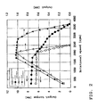
- FIG. 2 shows an experimental result obtained when the rotary electrical machine 7 having the structure described above operates as the electric motor. From the experimental result, it can be understood that, according to the rotary electrical machine 7, the output torque at every speed is larger than that of a conventional rotary electrical machine which field magnet is not changed. Additionally, the output power of the rotary electrical machine 7 is the maxim while the rotational speed exists between 1,800-2,800 rpm.
- transmission torque (input torque) is inputted to the rotational shaft 12 from the axle 4.
- the rotary electrical machine 7 makes a regenerative braking function as a generator to brake the electric vehicle 1.
- the force component generating mechanism 27 generates a force component (headed for the reverse direction relative to the right force component D, called “reverse force component” below), from the transmission torque T transmitted to the rotor 13 from the rotational shaft 12.
- This reverse force component is external force affecting the rotor 13 to the going direction A similar to the urging force C of the spring 26.
- the torque characteristic can be adjusted by adjusting the gap size E between the rotor 13 and the stator 14.
- desired characteristics can be obtained in connection with the relationships between the rotational speed and the output torque or between the rotational speed and the input torque.
- the rotor position changing mechanism 15 uses the portion of the transmission torque T as the driving force to move the rotor 13. That is, the rotary electrical machine 7 controls the field magnet based upon the transmission torque T directly relating to the output torque or the input torque on the rotational shaft 12. Accordingly, the rotary electrical machine 7 does not need any centrifugal governor, although the conventional art controls the field magnet using such a centrifugal governor which external size is large and which structure is complicated. The external size of the rotary electrical machine 7 thus can be compact, and the structure thereof can be simpler. Therefore, the electric vehicle 1 or the like can be downsized or can be simpler by applying the rotary electrical machine 7 to the electric vehicle 1 or the like.
- the rotary electrical machine 7 because the field magnet is controlled based upon the transmission torque T, the electrical loss can be diminished, in comparison with the conventional art in which the field magnet is controlled by supplying an electric current to an additional electromagnet.
- the amount of the current supplied to the stator and the amount of the current supplied to the electromagnet to move the rotor are in proportion to each other. Accordingly, an adjustable range of the characteristic of the rotary electrical machine is limited to be narrow. However, according to the rotary electrical machine 7, when it works as the electric motor, the characteristic is adjustable regardless of the amount of the current supplied to the stator 14. The degree of freedom for designing can be improved to this extent.
- the rotor position changing mechanism 15 changes the distance between the rotor 13 and the stator 14 in response to the magnitude of the transmission torque T.
- the field magnet established between the rotor 13 and the stator 14 is controlled to be strong or weak in response to the magnitude of the transmission torque T. Because of this control, the following effects can be obtained.
- the rotor 13 can stay at the position spaced apart from the stator 14 while the transmission torque T is small, and the rotor 13 can approach the stator 14 together with the increase of the transmission torque T.
- the rotary electrical machine 7 works as the electric motor
- the rotor 13 recedes from the stator 14 (the one dot chain lines of FIG. 1) while the output torque to the rotational shaft 12 from the rotor 13 is small, and the field magnet is weak.
- the rotational shaft 12 can rotate at a high speed.
- the running speed of the vehicle 1 under the condition that the output torque is small i.e., under the low torque condition, can be increased.
- the output torque of the rotational shaft 12 under a low speed rotational condition can be a high torque.
- the output torque in a starting operation or in an accelerating operation of the electric vehicle 1 can be the high torque. The starting or accelerating operations thus can be quickly made.
- the rotary electrical machine 7 works as the electric motor, the suitable characteristic can be obtained in which the high torque is given in the low speed operation, while the low torque is given in the high speed operation. Accordingly, the rotary electrical machine 7 can work in such a wide span ranging between the low speed high torque area to the high speed low torque area.
- the rotary electrical machine 7 when the rotary electrical machine 7 works as the generator, the rotary electrical machine 7 can makes the regenerating braking.
- the reverse force component can be generated from the transmission torque T which is the input torque to the rotational shaft 12, and the rotor 13 moves to the going direction A using the reverse force component as its driving force.
- the reverse force component becomes large, the rotor 13 recedes from the stator 14 and the field magnet becomes weak. Thus, an over-braking or an overcharging can be inhibited.
- the rotor position changing mechanism 15 includes the force component generating mechanism 27 generating the force component from the transmission torque T to move the rotor 13. Accordingly, the force component generating mechanism 27 directly provides the force component to the rotor in response to the magnitude of the transmission torque T.
- the external force for moving the rotor indirectly affects the rotor, for example, the conventional art in which the electromagnet attracting the rotational shaft is provided, a large loss is inhibited from being mechanically or electrically generated in moving the rotor 13.
- the rotor position changing mechanism 15 has the spring 26 urging the rotor 13 in the moving direction of the rotor 13.
- the degree of the approaching state or the receding state between the rotor 13 and the stator 14 can be freely set. Accordingly, no complicated device is necessary for adjusting the degree of the approaching state or the receding state of the rotor 13. Because the spring 26 is one of the members having a simple structure, the structure of the rotary electrical machine 7 can be simpler.
- another spring 26' urging the rotor 13 to the returning direction B can be provided in addition to the spring 26 in FIG. 1 that urges the rotor to the going direction A. That is, two springs 26, 26' which urging directions are opposed to each other can be provided. Each urging force of the spring 26 and the spring 26' can be properly set. For example, it is applicable that the urging force of the spring 26 is set larger than the urging force of the spring 26.' Therefore, the resultant force made up with the urging force of both the springs 26, 26' affects the rotor 13 to the going direction A, and the resultant force may be smaller than the attractive magnetic force F.
- the torque of the rotational shaft 12 is either the output torque or the input torque
- the respective desired field magnet controls can be realized by the springs 26, 26', and the applicable scope of the rotary electrical machine 7 can be expanded.
- the spring 26 is a spring having a non-linear characteristic.
- the approaching position or receding position of the rotor 13 relative to the stator 14 can be decided at will in response to the magnitude of the transmission torque T, and a desired torque characteristic can be obtained.
- the attractive magnetic force F generated between the rotor 13 and the stator 14 intrinsically has a non-linear characteristic relative to the distance between the rotor 13 and the stator 14.
- the non-linearity of the urging force C of the spring 26 can pseudoly make the characteristic of the resultant force made up with the urging force C and the attractive magnetic force F.
- the spring 26 has the multiple spring members 32 which free lengths differ from each other.
- the spring 26 can have any desired characteristics such as, for example, a non-linear characteristic in all, by, for example, using some springs having a linear characteristic as a part of the multiple spring members 32 and some other springs having a non-linear characteristic as the remainder part thereof.
- the structure of each spring member 32 having the linear characteristic is simple enough, the structure of the rotary electrical machine 7 can be simplified to this extent where it uses the simple spring members 32.
- the force component generating mechanism 27 has a helical structure that helically moves the rotational shaft 12 and the rotor 13 relative to each other about the axis 3.
- the force component can be generated from the transmission torque T between the rotational shaft 12 and the rotor 13, and the force component can be directly given to the rotor 13. Accordingly, the structure of the rotary electrical machine 7 can be simpler, and a large loss is inhibited from being mechanically or electrically generated in moving the rotor 13.
- the force component generating mechanism 27 is formed with the helical gear unit 34 positioned between the rotational shaft 12 and the rotor 13.
- the helical gear unit 34 is compact and has a simple structure. Accordingly, the rotary electrical machine 7 can be downsized and the structure thereof can be simplified.
- the rotary electrical machine 7 in this embodiment is the so-called flat type rotary electrical machine which rotor 13 generally has a disk shape, and the rotor 13 and the stator 14 face each other in the axial direction of the rotational shaft 12.
- the gap size E of the gap separating the rotor 13 and the stator 14 from each other varies.
- FIG. 4 Another rotary electrical machine is known.
- This machine is a type in which the rotor 13 and the stator 14 face in a radial direction of the rotational shaft 12.
- the gap size between the rotor 13 and the stator 14 does not vary; however, facing areas of the rotor 13 and the stator 14 vary.
- a change ratio of the torque characteristic of the rotary electrical machine 7 of this embodiment per unit moving distance of the rotor 13 is larger, because the gap size E varies as discussed above.
- a necessary moving distance of the rotor 13 can be shorter than that of the facing area variable type rotary electrical machine. Accordingly, the rotary electrical machine 7 can be compact. For example, by applying the rotary electrical machine 7 to the electric vehicle 1, the downsizing of this electric vehicle 1 can be more expedited.
- the characteristic of the spring 26 can be linear one.
- the respective spring members 32 of this spring 26 can have the same shape as one another, have the same size as one another, or have the same characteristic as one another.
- the force component generating mechanism 27 can have helical structures other than the helical gear unit 34 such as, for example, screws, ball screw mechanisms in which a plurality of balls are used, etc.
- the teeth 23 and the coils 24 can be placed on the rotor 13 side, while the permanent magnets 18 can be placed on the stator 14 side.
- the setting of the spring 26 of the first embodiment is changed so that the urging force C of the spring 26 is smaller that the attractive magnetic force F.
- the attractive magnetic force F moves the rotor 13 to the returning direction B until the rotor 13 abuts on the second stopper 29 regardless of the magnitude of the transmission torque T.
- the rotor 13 can be always placed at a position close to the stator 14 (see the actual lines in FIG. 1).
- the reverse force component is generated by the transmission torque T transmitted to the rotor 13 from the rotational shaft 12, and the reverse force component affects the rotor 13 to the going direction A.
- the reverse force component is small. If the resultant force made up with this reverse force component and the urging force C of the spring 26 is smaller than the attractive magnetic force F, the position of the rotor 13 is kept at the position close to the stator 14 (see the actual lines in FIG. 1). Thus, the gap size E is maintained to be small, and the field magnet is strong.
- the reverse force component is large, because the transmission torque T transmitted to the rotor 13 from the rotational shaft 12 is large. If the resultant force made up with this reverse force component and the urging force C of the spring 26 is sufficiently larger than the attractive magnetic force F, the resultant force moves the rotor 13 to the going direction A until the rotor 13 abuts on the first stopper 28, and the rotor 13 is always placed at a position spaced apart from the stator 14 (see the one dot chain lines of FIG. 1) . Thus, the gap size E is large, and the field magnet is weak.
- the reverse force component, the urging force C of the spring 26 and the attractive magnetic force F can be balanced with each other.
- the reverse force component, the urging force C and the attractive magnetic force F can balance with each other.
- the rotor 13 can be placed at a desired position between the first stopper 28 and the second stopper 29. The rotor 13 thus can rotate at the desired position. Accordingly, the characteristics of the rotary electrical machine 7 can be freely set. That is, for example, a setting in which the generating voltage of the rotary electrical machine 7 is generally fixed regardless of the rotational speed of the rotational shaft 12, or other similar free settings can be made.
- the rotary electrical machine 7 works as the generator, if, for example, the generated voltage is charged into a secondary battery, generating circuits such as, for example, a voltage rising circuit or a voltage lowering circuit can be simplified. Also, the characteristic of the rotary electrical machine 7 can be set to be a desired characteristic that is suitable for charging the voltage into the secondary battery.
- the third embodiment will be described.
- the spring 26 urging the rotor 13 to the going direction A is removed in the variation of the first embodiment, which has the springs 26, 26', to leave only the spring 26' that urges the rotor 13 to the returning direction B.
- the rotor 13 when the rotary electrical machine 7 operates as the electric motor, the rotor 13 receives the urging force C' of the spring 26' and the attractive magnetic force F. The rotor 13 moves to the returning direction B until it abuts on the second stopper 29 regardless of the magnitude of the transmission torque T. As a result, the rotor 13 is always placed at a position close to the stator 14 (see the actual lines in FIG. 3).
- the reverse force component is generated to affect the rotor 13 to the going direction A from the transmission torque (this transmission torque is equal to the input torque of the rotational shaft 12) T transmitted to the rotor 13 from the rotational shaft 12. If the input torque T of the rotational shaft 12 is small, the reverse force component is smaller than the resultant force made up with the urging force C' of the spring 26' and the attractive magnetic force F. On this occasion, the rotor 13 moves to the returning direction B to be placed at the position close to the stator 14 (see the actual lines of FIG. 7). As a result, the gap size E is small, and the field magnet between the rotor 13 and the stator 14 is strong.
- the reverse force component is larger than the resultant force made up with the urging force C' of the spring 26' and the attractive magnetic force F, and the rotor 13 moves to the going direction A until the rotor 13 abuts on the first stopper 28.
- the rotor 13 is placed at a position spaced apart from the stator 14 (see the one dot chain lines in FIG. 7).
- the gap size E is large, and the field magnet is weak.
- the helix angle of the helical gear unit 34 that generates the reverse force component, the spring constant of the spring 26' and other parameters are set to be desired values, the reverse force component, the urging force C of the spring 26' and the attractive magnetic force F can balance with each other.
- the rotor 13 can be placed at a desired position between the first stopper 28 and the second stopper 29. That is, the characteristic of the rotary electrical machine 7 can be freely set. For example, a setting in which the generating voltage of the rotary electrical machine 7 is generally fixed regardless of the rotational speed of the rotational shaft 12, or other similar free settings can be made.
- the rotary electrical machine 7 works as the generator, if, for example, the generated voltage is charged into a secondary battery, generating circuits such as, for example, a voltage rising circuit or a voltage lowering circuit can be simplified, and the characteristic of the rotary electrical machine 7 as the generator can be a desired characteristic that is suitable for charging the voltage into the secondary battery.
- the fourth embodiment is a rotary electrical machine 7 having a rotor 13 which shape is generally cylindrical.
- the permanent magnets 18 of the rotor 13 and the teeth 23 of the stator 14 face each other in a radial direction of the rotational shaft 12 (right to left direction in FIG. 4).
- the rotor 13 moves in the axial direction thereof, the rotor 13 approaches or recedes from the stator 14, and facing areas of the rotor 13 and the stator 14 facing each other vary. Because of this variation in the facing areas, the strength of the field magnet varies.
- the sentence "the rotor 13 approaches or recedes from the stator 14" in this specification means that the rotor 13 in all approaches or recedes from the stator 14, and should not be limited to the interpretation that the rotor moves so that the gap size between them varies as in the embodiment 1-3. Accordingly, the movement for changing the facing areas of the rotor and the stator can be included in the meaning of approaching or of receding.
- the transmission torque T is transmitted to the rotational shaft 12 from the rotor 13. If the load applied to the rotational shaft 12 is small, the transmission torque T transmitted to the rotational shaft 12 from the rotor 13 is small in accordance with the load. As a result, the force component D generated by the force component generating mechanism 27 is small. If the force component D is small, the urging force C of the spring 26 is large relative to the force component D, and the rotor 13 recedes from the stator 14 (see the one dot chain lines of FIG. 4) to make the facing areas small. Accordingly, the field magnet between the rotor 13 and the stator 14 is weak.
- the transmission torque T is also large together with the load.
- the force component D is large. If the force component is large, the rotor 13 approaches the stator 14 against the urging force C (see the actual lines in FIG. 4), and the facing areas become larger. Accordingly, the field magnet becomes stronger.
- the suitable torque characteristic i.e., the characteristic that brings the high torque while the speed is low and also the low torque while the speed is high, can be obtained by the compact and simple structure.
- the fifth embodiment is almost equal to the first embodiment except for that the force component generating mechanism 27 is modified.
- the rotor position changing mechanism 15 in the first embodiment generates the force component from the torque or power transmitted in the interior of the rotary electrical machine 7 using the force component generating mechanism 27, and moves the rotor 13 by the force component. Taking an attention to the function for moving the rotor 13, the rotor position changing mechanism 15 can be called "moving member.”
- the rotary electrical machine 7 has a moving member 41 that can transmit torque or power between the rotational shaft 12 and the rotor 13, can make the rotational shaft 12 and the rotor 13 rotate relative to each other about the axis 3, and can move the rotor 13 relative to the rotational shaft 12 in the axial direction by the relative rotation of the rotational shaft 12 and the rotor 13.
- the moving member 41 is formed with the helical gear unit 34.
- the moving member 41 is not limited to the helical structure such as, for example, the helical gear unit 34 or the like.
- the moving member 41 As thus constructed, by such a simple movement in which the rotational shaft 12 and the rotor 13 simply helically rotates relative to each other, the gap size E between the rotor 13 and the stator 14 can be changed, or the facing areas of the rotor 13 and the stator 14 can be changed (see the fourth embodiment).
- the characteristic of the rotary electrical machine 7 can be changed. That is, using the moving member 41, the characteristic of the rotary electrical machine 7 is changeable by the simple structure.
- the moving member 41 is formed with an engaging structure in which the rotational shaft 12 and the rotor 13 engage with each other, and engaging portions thereof helically extend about the axis 3 of the rotational shaft 12.
- the force component of the transmission torque T is generated between the rotational shaft 12 and the rotor 13, the force component is given to either one of the rotational shaft 12 and the rotor 13 from the other one through the engaging portions. Because the engaging portions helically extend, the rotor 13 receiving the force component moves along a longitudinal direction of the engaging portions. That is, the rotor 13 helically moves relative to the rotational shaft 12.
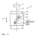
- FIG. 5 shows the first specific example of the moving member 41.
- the moving member 41 is formed with a cam unit 36 having a helical structure.
- This cam unit 36 is positioned between the rotational shaft 12 and the rotor 13, and helically moves the rotational shaft 12 and the rotor 13 relative to each other about the axis 3 using a portion of the transmission torque T as the driving force.
- the cam unit 36 includes a helically shaped cam hole 37 formed on either one of the rotational shaft 12 and the rotor 13, and a cam projection 38 formed on the other one.
- the cam projection 38 is fitted into the cam hole 37 to engage with the cam hole 37. In the example shown in FIG. 5, the cam projection 38 extends from the rotational shaft 12, while the cam hole 37 is made at the rotor 13.
- the cam unit 36 is a compact and simple mechanism.
- the moving member 41 can be realized with the compact and simple structure.
- the rotary electrical machine 7 can be a compact and simple structure.
- the so-called concave and convex engaging structure can be suitably used as the engaging structure of the moving member 41. That is, the moving member 41 can include a concave 42 formed on either one of the rotational shaft 12 and the rotor 13 and helically extending therefrom, and a convex 43 formed on the other one and engaging with the concave 42.
- the moving member 41 can include a concave 42 formed on either one of the rotational shaft 12 and the rotor 13 and helically extending therefrom, and a convex 43 formed on the other one and engaging with the concave 42.
- helical tooth bottom ends of the helical gear unit 34 or the helically shaped cam hole 37 of the cam unit 36 correspond to the concave 42
- helical tooth top ends of the helical gear unit 34 or the cam projection 38 of the cam unit 36 correspond to the convex 43.
- concave 42 and the convex 43 are not limited to those of the embodiments.
- a helically shaped slot penetrating the rotational shaft 12 can be the concave 42, while a pin having distal ends supported by the rotor 13 and being fitted into the slot can be the convex 43.
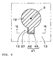
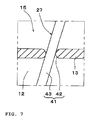
- FIGs. 6 and 7 show the second specific example of the moving member 41.
- the outer circumferential surface of the rotational shaft 12 has the convex 43 helically extending about the axis 3, while the inner circumferential surface of the rotor 13 has the concave 42 engaging with the convex 43.
- the moving member 41 is formed with those concave 42 and the convex 43.
- the concave 42 does not helically extend, and the concave 42 and the convex 43 engage with other in such a manner that two points of the inner surface of the concave 42 interpose a portion of the convex 43 in its longitudinal direction therebetween.
- the gap size E between the rotor 13 and the stator 14 can vary, or the facing areas thereof can be varied.
- the characteristic of the rotary electrical machine 7 can vary because of the engagement of the concave 42 and the convex 43 with each other.
- the engaging structure formed with the concave 42 and the convex 43 is relatively a simple structure. Thus, by this simple structure, the characteristic of the rotary electrical machine 7 can be changed.
- both of the concave 42 and the convex 43 of the moving member 41 are helically shaped as the helical gear unit 34, larger torque can be transmitted in comparison with the structure in which only one of them is helically shaped. Accordingly, the rotor 13 can more smoothly and certainly move in the axial direction.
- the present invention is useful with a rotary electrical machine and an electric vehicle having the rotary electrical machine.
Landscapes
- Engineering & Computer Science (AREA)
- Power Engineering (AREA)
- Permanent Magnet Type Synchronous Machine (AREA)
- Connection Of Motors, Electrical Generators, Mechanical Devices, And The Like (AREA)
- Electric Propulsion And Braking For Vehicles (AREA)
- Iron Core Of Rotating Electric Machines (AREA)
Abstract
Description
- The present invention relates to a rotary electrical machine and an electric vehicle having such rotary electrical machine.
- Conventionally, a rotary electrical machine is known, the machine having a rotor, a rotational shaft attached to the rotor, and a stator, and controlling the strength of the field magnet established between the rotor and the stator in response to a rotational speed of the rotor. In this kind of rotary electrical machine, by controlling the strength of the field magnet, the characteristic of the rotary electrical machine (such as, for example, a relationship between the rotational speed and the output torque of the rotational shaft) can be adjusted.
- As one of such rotary electrical machines, for example, the rotary electrical machine disclosed in JP-A-Hei11-122886 (called "Patent Document 1" below) is known. This rotary electrical machine includes a housing which is a stationary side member and forms an outer shell of the rotary electrical machine, a rotational shaft journaled on the housing for rotation about an axis thereof, but not for movement in the axial direction thereof, a rotor coupled with the rotational shaft to rotate about the axis together with the rotational shaft, a stator supported by the housing so as to face the rotor, and a centrifugal governor joined to a distal end of the rotational shaft. A yoke which forms the stator has multiple receiving apertures that extends parallel to the axial direction of the rotational shaft (can be simply described as "extending in the axial direction" below). Each auxiliary yoke which extends in the axial direction of the rotational shaft is inserted into a corresponding receiving aperture. Each auxiliary yoke is connected to the centrifugal governor. The centrifugal governor moves the associated auxiliary yoke in the axial direction. That is, an inserted length of each auxiliary yoke is variable in accordance with the rotational speed of the rotational shaft. Thus, the reluctance of the yoke varies in response to the rotational speed of the rotational shaft, and the strength of the field magnet established between the rotor and the stator can be adjusted.
- When the rotary electrical machine operates as an electric motor, an electric current is supplied to the stator so that the rotor rotates. With the rotation of the rotor, the rotational shaft generates output torque. In the rotary electrical machine described above, if the rotational shaft makes a high speed rotation, the field magnet is weaken because of an action of the centrifugal governor. As a result, the output torque per unit current (i.e., output torque of the rotational shaft generated per unit current flowing through the stator) becomes small. As thus discussed, by weakening the field magnet, the rotational shaft can rotate at a high speed under a low torque condition.
- Conversely, when the rotational shaft rotates at a low speed, the field magnet can be strengthened by the action of the centrifugal governor operating in association with the rotational shaft. As a result, the output torque per unit current becomes large. Thus, by strengthening the field magnet, the rotational shaft can rotate at a low speed under a high torque condition.
- That is, according to the rotary electrical machine described above, when it operates as an electric motor, a torque characteristic can be obtained in which the rotational speed becomes high while the output torque of the rotational shaft is small, and also the output torque becomes large while the rotational speed is low.
- JP-A-Hei03-215154 (called "
Patent Document 2" below) discloses a rotary electrical machine in which the strength of the field magnet between a rotor and a stator is adjusted by making the rotor approach or recede from the stator. This rotary electrical machine includes a stationary side member, a rotational shaft journaled on the stationary side member for rotation about an axis thereof, the rotor coupled with the rotational shaft to rotate about the axis, the stator supported by the stationary side member so as to face the rotor, a spring urging the rotational shaft in a direction in which the rotor recedes from the stator, and an electromagnet electrically connected to the stator in series. The rotational shaft is formed of a magnetic material. In this rotary electrical machine, when an electric current is supplied to the electromagnet, the electromagnet attracts the rotational shaft in the axial direction. If the attractive force of the electromagnet is larger than the urging force of the spring, the rotor approaches the stator. Conversely, the attractive force of the electromagnet is smaller than the urging force of the spring, the rotor recedes from the stator. As thus discussed, the electromagnet and the spring together form an actuator that moves the rotational shaft in the axial direction. - When the rotary electrical machine described above operates as an electric motor, an electric current is supplied to the stator and the electromagnet to rotate the rotor. If the load applied to the rotational shaft is small, the current supplied to the stator is small. Thus, the current supplied to the electromagnet is also small, and the electromagnetic force of the electromagnet is small. Accordingly, the force of the electromagnet that attracts the rotational shaft is smaller than the urging force of the spring, and the rotor is kept separate from the stator. Consequently, the gap size between the rotor and the stator is large to keep the field magnet weak.
- On the other hand, as the load applied to the rotational shaft becomes large, the current supplied to the stator becomes large. Thus, the current supplied to the electromagnet also becomes large, and the attractive force of the electromagnet becomes larger than the urging force of the spring. Because of the attractive force of the electromagnet, the rotational shaft moves to the direction in which the rotor approaches the stator. Consequently, the gap size between the rotor and the stator becomes smaller to strengthen the field magnet.
- Thus, also according to the rotary electrical machine disclosed in
Patent Document 2, the same torque characteristic as that of the rotary electrical machine disclosed in Patent Document 1 can be obtained. That is, also according to the rotary electrical machine disclosed inPatent Document 2, when it operates as an electric motor, the torque characteristic can be obtained in which the rotational speed is high while the output torque of the rotational shaft is small, and also the output torque is large while the rotational speed is low. - The rotary electrical machine disclosed in Patent Document 1 needs a centrifugal governor attached to the rotational shaft to obtain the torque characteristic discussed above. However, because the centrifugal governor generates the centrifugal force using a weight, the governor needs some structure that moves the weight in a radial direction of the rotor. In order to ensure a space for the movement of the weight, the rotary electrical machine needs to have a certain capacity in the radial direction. Accordingly arises a problem such that the external size of the rotary electrical machine having the centrifugal governor is inevitably large. Also, because the receiving apertures, the auxiliary yokes and the like described above are necessary in addition to the centrifugal governor, another problem arises such that the structure of the rotary electrical machine is complicated.
- The rotary electrical machine disclosed in
Patent Document 2 needs to have the above-described actuator provided outside of the rotational shaft in the axial direction. The length of the rotary electrical machine in the axial direction can be longer correspondingly to the length of the actuator. Thus, the size of the rotary electrical machine is inevitably large. A large space thus is necessary for placing the rotary electrical machine. - Patent Document 1: JP-A-Heill-122886
- Patent Document 2: JP-A-Hei03-215154
- The present invention is made under the circumstances described above, and an object thereof is to downsize external dimensions of a rotary electrical machine, and also to simplifies a structure of the machine, in which a rotor is moved in an axial direction thereof to make the rotor approach or recede from a stator, thereby the strength of the field magnet established between the rotor and the stator is controllable.
- Also, another object of the present invention is, in the rotary electrical machine, to make the rotor movable in the axial direction without inviting the upsizing of the external dimensions or making the structure complicated.
- A rotary electrical machine according to the present invention includes a base member; a stator fixed to the base member; a rotational shaft supported by the base member for rotation; a rotor coupled with the rotational shaft and facing the stator to mutually transmit torque with the rotational shaft therebetween; and a rotor position changing mechanism for making the rotor approach the stator or for making the rotor recede from the stator along an axial direction of the rotational shaft in response to the magnitude of the transmission torque between the rotational shaft and the rotor.
- When the rotary electrical machine described above operates as an electric motor, the torque is transmitted to the rotational shaft from the rotor to drive the rotational shaft. On the other hand, when the rotary electrical machine operates as a generator, the torque is transmitted to the rotor from the rotational shaft to drive the rotor. Thus, under the operational condition of the rotary electrical machine, the torque is transmitted between the rotational shaft and the rotor. Additionally, the rotary electrical machine is not limited to such a machine operating as either the electric motor or the generator. It can be a machine that operates only as the electric motor or as the generator.
- Because the rotary electrical machine has the rotor position changing mechanism, the rotor approaches or recedes from the stator in response to the magnitude of the transmission torque between the rotational shaft and the rotor. In this regard, the field magnet established between the rotor and the stator becomes strong while the rotor approaches the stator, and, conversely, it becomes weak while the rotor recedes from the stator. Accordingly, the strength of the rotary electrical machine is controlled in response to the magnitude of the transmission torque between the rotational shaft and the rotor. In accordance with the field magnet controlled in such a manner, the relationship between the rotational speed and the torque of the rotational shaft, i.e., the torque characteristic varies. As a result, by properly controlling the field magnet, the torque characteristic of the rotary electrical machine can be desirably changed. For example, the torque characteristic can be realized in which, when the rotary electrical machine operates as the electric motor, the output torque is large while the rotational speed is in a low speed range, and the output torque is small while the rotational speed is in a high speed range. Thus, for example, the rotary electrical machine can operate in a wide operational range.
- According to the rotary electrical machine, differently from the rotary electrical machine of Patent Document 1, no centrifugal governor, which external size is large and which structure is complicated, is not required. Accordingly, the external dimensions of the rotary electrical machine can be downsized. Also, the structure of the rotary electrical machine can be simplified. By applying this rotary electrical machine to an electric vehicle, the downsizing and the simplification of the structure can be achieved for the electric vehicle.
- Also, according to the rotary electrical machine, differently from the rotary electrical machine of
Patent Document 2, no electromagnet which attracts the rotational shaft in the axial direction needs to be additionally provided. Thus, the downsizing of the external dimensions and the simplification of the structure can be achieved for the rotary electrical machine. Also, because the stator and the electromagnet of the rotary electrical machine disclosed inPatent Document 2 are connected to each other in series, the amount of the current supplied to the stator and the amount of the current supplied to the electromagnet are in proportion to each other. Accordingly, an adjustable range of the torque characteristic of the rotary electrical machine is limited to be narrow. To the contrary, according to the rotary electrical machine described above, the torque characteristic is adjustable regardless of the amount of the current supplied to the stator. The degree of freedom for designing can be therefore improved. - Preferably, the rotor position changing mechanism includes a force component generating mechanism for generating a force component that moves the rotor in the axial direction of the rotational shaft, from the transmission torque transmitted between the rotational shaft and the rotor.
- Thereby, a force component is generated from the transmission torque, and the rotor moves in the axial direction of the rotational shaft by receiving the force component. Accordingly, the field magnet is controlled by the force component of the transmission torque. Thus, differently from the rotary electrical machine of
Patent Document 2 which uses the electromagnet for moving the rotor, an electrical loss can be diminished. Also, in the rotary electrical machine ofPatent Document 2, the external force for moving the rotor affects the rotational shaft. That is, the external force for moving indirectly affects the rotor through the rotational shat. To the contrary, according to the rotary electrical machine described above, the force component directly affects the rotor. Thus, in moving the rotor, a large loss is inhibited from being mechanically or electrically generated. - Another rotary electrical machine according to the present invention includes a base member; a stator fixed to the base member; a rotational shaft supported by the base member for rotation; a rotor coupled with the rotational shaft and facing the stator to mutually transmit torque with the rotational shaft therebetween; and a rotor position changing mechanism for making the rotor approach the stator or for making the rotor recede from the stator using a portion of the transmission torque transmitted between the rotational shaft and the rotor as driving force.
- In this rotary electrical machine also, the rotor is moved by the force component of the transmission torque to approach or recede from the stator. The action and the effect described above thus can be obtained.
- The rotor position changing mechanism can make the rotor approach the stator when the transmission torque transmitted to the rotational shaft from the rotor increases.
- Thereby, when the rotary electrical machine operates as the electric motor, if the torque transmitted to the rotational shaft from the rotor increases, the rotor approaches the stator, and the field magnet between the rotor and the stator becomes strong. Thus, under the condition that the load applied to the rotational shaft is large, the output torque of the rotational shaft can be large. Therefore, for example, if the rotary electrical machine is used as a driving force source of an electric vehicle for running, the output torque of the electric vehicle in a starting operation or in an accelerating operation can be large. Quick start or acceleration can be realized.
- The rotor position changing mechanism can make the rotor recede from the stator when the transmission torque transmitted to the rotational shaft from the rotor decreases.
- Therefore, when the rotary electrical machine operates as the electric motor, if the torque transmitted to the rotational shaft from the rotor decreases, then the rotor recedes from the stator, and the field magnet between the rotor and the stator becomes weak. Thus, under the condition that the load applied to the rotational shaft is small, the rotational shaft can rotate at a high speed. Thereby, for example, if such rotary electrical machine applies to the electric vehicle, the running speed of the vehicle under the condition that the output torque is small, i.e., under a low torque condition, can be high.
- The rotor position changing mechanism can make the rotor recede from the stator when the transmission torque transmitted to the rotor from the rotational shaft increases.
- Thereby, when the rotary electrical machine operates as the generator, if the torque transmitted to the rotor from the rotational shaft increases, the rotor recedes from the stator, and the field magnet between the rotor and the stator becomes weak. Thus, an overcharge by the rotary electrical machine can be inhibited. Also, when the rotary electrical machine makes a regenerative braking, an over-braking can be inhibited.
- Further, when the rotor has moved to a desired position, if the force by which the rotor position changing mechanism forces the rotor to recede from the stator and the attractive magnetic force generated between the rotor and the stator balance with each other, the rotor can be placed at a desired position regardless of the rotational speed of the rotational shaft. That is, the voltage generated by the rotary electrical machine can be nearly fixed. Thus, by adjusting the force that makes the rotor recede from the stator, the generating characteristic of the rotary electrical machine (or the braking characteristic thereof when the regenerating braking is made) can be freely set. If the generated voltage is charged into a secondary battery, generating circuits such as, for example, a voltage rising circuit or a voltage lowering circuit can be simplified. Also, the characteristic of the rotary electrical machine can be adjusted so as to be suitable for charging.
- Preferably, the rotor position changing mechanism has a spring urging the rotor to a direction in which the rotor approaches the stator or to a direction in which the rotor recedes from the stator.
- Thus, by adjusting the characteristic of the spring, the degree of the approaching state or the receding state between the rotor and the stator can be freely set. Accordingly, by adjusting the characteristic of the spring, the torque characteristic of the rotary electrical machine can be adjusted. Because it is easy to adjust the characteristic of the spring, the torque characteristic of the rotary electrical machine can be easily adjusted. Also, because the spring has a simple structure, the adjustment of the torque characteristic can be realized by such a simple structure.
- Preferably, the spring includes a first spring member urging the rotor to the direction in which the rotor approaches the stator, and a second spring member urging the rotor to the direction in which the rotor recedes from the stator.
- Thereby, even though the torque of the rotational shaft is either one of the output torque or the input torque (in other words, even though the rotary electrical machine operates as the electric motor or operates as the generator), respective desired field magnet controls can be expedited by both of the spring members, and the applicable limits of the rotary electrical machine can be expanded.
- Preferably, the spring has a non-linear characteristic.
- By using the spring having such a non-linear characteristic, the movement characteristic of the rotor can be properly adjusted. Thus, an approaching position or receding position of the rotor relative to the stator can be decided at will, and a desired torque characteristic can be obtained. For example, a non-linear attractive magnetic force which may be generated between the rotor and the stator can be adjusted so that linear force affects the rotor.
- Preferably, the spring includes multiple spring members each having a characteristic different from each other, and the respective spring members being coupled with each other.
- For example, by using some of the multiple springs as those having a simple structure of a linear characteristic and using the remainder of the multiple springs as those having another characteristic, a desired characteristic as a whole of those springs can be obtained, such as a non-linear characteristic, for example. Thus, using springs having the simple structure, the structure of the rotary electrical machine can be simpler.
- Preferably, the force component generating mechanism has a helical structure in which the rotational shaft and the rotor are capable of helically moving relative to each other about the axis of the rotational shaft.
- Thereby, using such a helical structure which is mechanically simple, the force component is generated from the transmission torque between the rotor and the rotational shaft. The rotor receives the force component and moves to the direction in which it approaches the stator or to the direction in which it recedes from the stator. Accordingly, the structure of the rotary electrical machine can be simpler, and no loss can be mechanically or electrically generated with the movement of the rotor.
- Preferably, the force component generating mechanism has an engaging structure by which the rotational shaft and the rotor engage with each other, and at least a portion of the engaging structure helically extends about the axis of the rotational shaft.
- Thereby, the force component is generated from the transmission torque in the engaging portions of the rotor and the rotational shaft. Because at least a portion of the engaging structure helically extends about the axis, the rotor helically moves relative to the rotational shaft when the rotor receives the force component. As a result, the rotor moves to the direction in which it approaches the stator or to the direction in which it recedes from the stator. Thus, by the simple structure, i.e., the engaging structure, the force component can be generated from the transmission torque, and the movement of the rotor can be guided.
- Preferably, the force component generating mechanism has a helical gear unit positioned between the rotational shaft and the rotor.
- In this regard, because the helical gear unit is a relatively compact and simple unit, the rotary electrical machine can be downsized and can be simpler to this extent.
- The force component generating mechanism can have a cam unit positioned between the rotational shaft and the rotor.
- In this regard, because the cam unit is a relatively compact and simple unit, the rotary electrical machine can be downsized and can be simpler to this extent.
- Preferably, a size of a gap separating the rotor and the stator from each other varies in accordance with approach or receding of the rotor relative to the stator.
- The strength of the field magnet between the rotor and the stator greatly depends on a size of a gap between the rotor and the stator. Thus, according to the rotary electrical machine described above, the strength of the field magnet can change on a large scale even though the movement amount of the rotor is small. Conversely, the movement amount of the rotor necessary for obtaining a desired torque characteristic can be small enough. This can advantageously reduce the space for the movement of the rotor. The rotary electrical machine can be downsized, accordingly. For example, the electric vehicle can be downsized if the rotary electrical machine applies to the electric vehicle.
- Preferably, the rotor and the stator face each other in a direction which is parallel to the axial direction of the rotational shaft.
- Additionally, the term "axial direction of the rotational shaft" noted above means not only the direction that is consistent with the axis of the rotational shaft but also the direction parallel to the axis of the rotational shaft.
- Thereby, when the rotor moves in the axial direction of the rotational shaft, the size of the gap between the rotor and the stator changes. Accordingly, the rotary electrical machine can be downsized, as discussed above.
- Another rotary electrical machine according to the present invention includes a base member; a stator fixed to the base member; a rotational shaft supported by the base member for rotation; a rotor coupled with the rotational shaft and facing the stator to mutually transmit torque with the rotational shaft therebetween; and a moving member for making the rotational shaft and the rotor rotate relative to each other about the axis of the rotational shaft, and for making the rotor move relative to the rotational shaft in the axial direction thereof by the relative rotation of the rotational shaft and the rotor to each other.
- In the rotary electrical machine, the moving member makes the rotor move in the axial direction of the rotational shaft relative thereto by the simple rotation of the rotational shaft and the rotor relative to each other. Thus, for example, by changing the gap size between the rotor and the stator, by changing the respective facing areas of the rotor and the stator, or by other similar measures, the characteristic of the rotary electrical machine can be freely changed. That is, the change of the characteristic of the rotary electrical machine can be achieved by the compact and simple structure.
- Another rotary electrical machine according to the present invention includes a base member; a stator fixed to the base member; a rotational shaft supported by the base member for rotation; a rotor coupled with the rotational shaft and facing the stator to mutually transmit torque with the rotational shaft therebetween; and a moving member for moving the rotor relative to the rotational shaft using a portion of the transmission torque transmitted between the rotational shaft and the rotor as driving force.
- In this rotary electrical machine, the moving member moves the rotor relative to the rotational shaft using the portion of the transmission torque transmitted between the rotational shaft and the rotor. Accordingly, because of the compact and simple structure, the characteristic of the rotary electrical machine can be changed. Also, differently from the conventional art in which the electromagnet is used for moving the rotor, the electrical loss that may be caused with the movement of the rotor can be inhibited. Further, in the conventional art, the external force for moving the rotor indirectly affects the rotor through the rotational shaft. To the contrary, according to the rotary electrical machine described above, the force generated for moving the rotor directly affects the rotor. Thus, in the movement of the rotor, a large loss is inhibited from being mechanically or electrically generated.
- Preferably, the moving member has an engaging structure for engaging the rotational shaft and the rotor with each other, and at least a portion of the engaging structure helically extends about the axis of the rotational shaft.
- Thereby, in the engaging portion of the rotor and the rotational shaft, the force component can be generated from the transmission torque. The rotor receives this force component to move in the axial direction of the rotational shaft. Accordingly, by the relatively simple structure, i.e., the engaging structure, the driving force for moving the rotor can be generated from the transmission torque.
- Preferably, the moving member has a convex formed at either one of the rotational shaft and the rotor, and a concave formed at the other one thereof.
- Thus, according to the moving member, by rotating the rotational shaft and the rotor relative to each other under the condition that the convex and the concave engage with each other, the gap size between the rotor and the stator can be changed, or by changing the respective areas of the rotational shaft and the rotor, the characteristic of the rotary electrical machine can be freely changed. Because both the convex and the concave are simple structures, the change of the characteristic of the rotary electrical machine can be achieved by the simple structure. Also, because the moving member is formed with the convex and the concave engaged with each other, large torque can be transmitted.
- Preferably, at least either one of the convex and the concave helically extends about the axis of the rotational shaft.
- Thus, when the rotational shaft and the rotor rotate relative to each other about the axis, the rotor helically moves relative to the rotational shaft of the rotor. As a result, the rotor smoothly moves relative to the rotational shaft of the rotor.
- An electric vehicle of the present invention includes the rotary electrical machine as a driving force source for running.
- This provides a suitable electric vehicle.
- As thus described, according to the present invention, the compact and simple structure can make the rotor approach or recede from the stator. Thus, the strength of the field magnet between the rotor and the stator can be controlled. In addition, the rotor can be moved in the axial direction of the rotational shaft without inviting the upsizing of the external dimensions or making the structure complicated.
-
- FIG. 1 is a cross sectional plan view of a rotary electrical machine according to a first embodiment.
- FIG. 2 is a graph, comparatively showing a torque characteristic of the first embodiment and a conventional torque characteristic.
- FIG. 3 is a cross sectional plan view of a rotary electrical machine according to a third embodiment.
- FIG. 4 is a cross sectional plan view of a rotary electrical machine according to a fourth embodiment.
- FIG. 5 is a cross sectional plan view, showing a first specific example of a moving member according to a fifth embodiment.
- FIG. 6 is a cross sectional plan view, showing a second specific example of the moving member according to the fifth embodiment.
- FIG. 7 is a cross sectional view, taken along the line VII-VII of FIG. 6.
-
- 1: electric vehicle
- 3: axis
- 7: rotary electrical machine
- 11: housing (base member)
- 12: rotational shaft
- 13: rotor
- 14: stator
- 15: rotor position changing mechanism
- 26: spring
- 27: force component generating mechanism
- 34: helical gear unit
- 36: cam unit
- 41: moving member
- 42: convex
- 43: concave
- Embodiments of the present invention will be described using figures below. The following respective embodiments are those in which a rotary electrical machine according to the present invention applies to an electric vehicle. However, the application of the rotary electrical machine is not limited the electric vehicle.
- With reference to FIGs. 1 and 2, a first embodiment will be described.
- In FIG. 1, the reference numeral 1 indicates the electric vehicle. The electric vehicle 1 of this embodiment is a motorcycle which is a kind of straddle type vehicle. However, the electric vehicle according to the present invention is not limited to the straddle type vehicle. The arrow Fr indicates the advance direction of the electric vehicle 1, i.e., the forward direction.
- The electric vehicle 1 includes a vehicle body, which is not shown, and a
rear arm 2 supported by the vehicle body for up and down swing movement relative to the vehicle body. Therear arm 2 has anaxle 4 at a swing end in a rear portion of therear arm 2, theaxle 4 extending in a width direction of the vehicle body (i.e., up to down direction of FIG. 1) and being supported for rotation about anaxis 3. Adrive wheel 5 for running which is a rear wheel is coupled with theaxle 4. The electric vehicle 1 additionally has a rotaryelectrical machine 7 as a driving force source for running and at least operating as an electric motor. The rotaryelectrical machine 7 is coupled with thedrive wheel 5 through theaxle 4 and a planetary gearedspeed reduction mechanism 6. The rotaryelectrical machine 7 is disposed on theaxis 3. The rotaryelectrical machine 7, however, can be spaced apart from theaxis 3 as long as it is coupled with thedrive wheel 5. - The rotary
electrical machine 7 has ahousing 11 as a base member, arotational shaft 12 disposed in the interior of thehousing 11, arotor 13, and astator 14. In this electric vehicle 1, a rear end portion of therear arm 2 forms thehousing 11. Additionally, because thehousing 11 can be considered to be standstill relative to the rotation of therotational shaft 12, thehousing 11 can be called "stationary side member." Therotational shaft 12 is journaled on thehousing 11 for rotation about theaxis 3 thereof and not for movement in the axial direction thereof. Therotor 13 is coaxially coupled with therotational shaft 12 to rotate about theaxis 3 together with the rotation of therotational shaft 12. Thestator 14 is fixed to thehousing 11 so as to face therotor 13. Therotor 13 and thestator 14 face each other in the axial direction of the rotational shaft 12 (i.e., the up to down direction in FIG. 1). - A rotor
position changing mechanism 15 is additionally disposed in the interior of thehousing 11. The rotorposition changing mechanism 15 moves therotor 13 in the direction of therotational shaft 13 using a portion of the torque (transmission torque) T transmitted between therotational shaft 12 and therotor 13 as driving force to change the position of therotor 13 relative to thestator 14. Additionally, in the following description, a direction in which therotor 13 recedes from thestator 14 is called "going direction A" and another direction in which therotor 13 approaches thestator 14 is called "returning direction B." Although details will be described later, this rotorposition changing mechanism 15 not only makes the rotor approach thestator 14 or recede from thestator 14 but also changes the position of therotor 13 relative to thestator 14 in response to the magnitude of the transmission torque T. - The entire configuration of the
rotor 13 is generally a disk-shape. Specifically, therotor 13 has ayoke 17 into which therotational shaft 12 is fitted andpermanent magnets 18 affixed to theyoke 17. Theyoke 17 includes acylindrical boss 19 having an aperture through which therotational shaft 12 extends and a generally disk-shapedyoke body 20 supported by theboss 19. Theyoke body 20 is made of a magnetic material. Eachpermanent magnet 18 is supported by an outer circumference of one surface of the yoke body 20 (i.e., the lower surface in FIG. 1). - The
stator 14 includesteeth 23 fixed to thehousing 11 with a fastener and coils 24 wound around therespective teeth 23. Theteeth 23 face thepermanent magnets 18 of therotor 13 in the axial direction of therotational shaft 12. - When an electric current flows through the
coils 24 of thestator 14, attractive magnetic force F is generated between thepermanent magnets 18 and thestator 14 so that both of them attract each other. As a result, therotor 13 is provided with external force which affects therotor 13 to a direction in which therotor 13 approaches thestator 14. That is, the external force goes to the returning direction B. Additionally, when therotor 13 moves in the going direction A or in the returning direction B, the own weight of therotor 13 actually affects the movement of therotor 13 to some extent. However, the influence of the own weight of therotor 13 is not considered in the following description. - The rotor
position changing mechanism 15 includes aspring 26 urging therotor 13 to a direction in which therotor 13 recedes from thestator 14, and a forcecomponent generating mechanism 27 generating a force component that moves therotor 13 in the axial direction of therotor 13 from the transmission torque between therotor 12 and therotational shaft 12. One end of thespring 26 is attached to thehousing 11, while the other end of thespring 26 is connected to a block 50. The block 50 is coupled with theboss 19 of therotor 13 throughbearings 51 and so forth. Accordingly, the block 50 journals therotor 13 for rotation about theaxis 3, and moves together with therotor 13 in the axial direction of therotational shaft 12. The urging force of thespring 26 affects therotor 13 through the block 50. A first stopper 28 and asecond stopper 29 are disposed on respective ends of theboss 19 of therotor 13 in the axial direction, the first stopper 28 preventing therotor 13 from receding from thestator 12 more than a preset distance, while thesecond stopper 29 preventing therotor 13 from approaching thestator 12 less than another preset distance. - The
spring 26 is set in such a manner that the urging force of thespring 26 is greater than the attractive magnetic force F between therotor 13 and thestator 14. Accordingly, when the transmission torque T is not more than a preset value (including T=0), the urging force of thespring 26 is greater than the attractive magnetic force F, and therotor 13 is placed at a position spaced apart from the stator 14 (see the one dot chain lines of FIG. 1, called "initial position" below). Thespring 26 has a characteristic with which a load and a displacement amount are not in proportion to each other within a movable range of therotor 13, i.e., non-linear characteristic. In this embodiment, thespring 26 includesmultiple spring members 32 which free lengths differ from each other. However, the type, shape, structure, material, characteristic, etc. of thespring 26 are not limited to specific ones. For example, thespring 26 can be formed with multiple spring members which characteristics differ from each other. - As described above, the force
component generating mechanism 27 is the mechanism that generates the force component moving therotor 13 in the axial direction, from the transmission torque T between therotor 13 and therotational shaft 12. Also, the forcecomponent generating mechanism 27 has the so-called helical structure to helically move therotational shaft 12 and therotor 13 about theaxis 3 relative to each other using the force component of the transmission torque T. That is, the forcecomponent generating mechanism 27 has a mechanically helical structure which can make therotational shaft 12 and therotor 13 helically move about theaxis 3 relative to each other. - In this embodiment, the force
component generating mechanism 27 is constructed with a helical gear unit 34 which center is theaxis 3. The helical gear unit 34 is positioned between theboss 19 of theyoke 17 and therotational shaft 12 fitted into theboss 19. Specifically, an outer section of the helical gear unit 34 is formed on an outer surface of therotational shaft 12, while an inner section of the helical gear unit 34 is formed on an inner surface of theboss 19, and the outer and inner sections engage with each other. By the engagement of therotational shaft 12 and theboss 19 with each other as discussed above, the force component is generated from the transmission torque T between therotational shaft 12 and theboss 19. The force component helically moves therotational shaft 12 and theboss 19 relative to each other. Additionally, the outer section and the first stopper 28 are unitarily formed with each other. - In this embodiment, when the electric vehicle 1 runs in the advance direction, the
rotational shaft 12 rotates clockwise (see the arrow of the transmission torque T in FIG. 1). Thus, in order to generate a force component in a predetermined direction from the transmission torque T, a helical gear unit having a right handed screw configuration is used as the helical gear unit 34. That is, in this embodiment, when the transmission torque T is transmitted toward therotational shaft 12 from therotor 13, the helical gear unit 34 generates the force component D headed for a direction in which therotor 13 approaches the stator 14 (called "right force component" below). - When the helical gear unit 34 rotates while the outer and inner sections thereof engage with each other, the
rotor 13 moves in the axial direction. The movement direction of the rotor 13 (i.e., going direction A or returning direction B) is decided in accordance with the urging force C of thespring 26 affecting in the going direction A, the attractive magnetic force F affecting between therotor 13 and thestator 14 in the returning direction B, and the right force component D affecting in the returning direction B. - When the
rotor 13 moves in the going direction A with the slide movement of the outer and inner sections, the respectivepermanent magnets 18 of therotor 13 recede from theteeth 23 of thestator 14 along the axial direction of therotational shaft 12. Also, a gap size E of a gap (space) separating eachpermanent magnet 18 of therotor 13 and therespective tooth 23 of thestator 14 from one another becomes larger. When therotor 13 further moves toward the going direction A, theboss 19 of theyoke 17 of therotor 13 abuts on the first stopper 28 so as to prevent the further movement of the rotor 13 (see the one dot chain lines in FIG. 1). - On the other hand, when the
rotor 13 moves in the returning direction B with the slide movement of the outer and inner sections, the respectivepermanent magnets 18 of therotor 13 approach theteeth 23 of thestator 14 along the axial direction of therotational shaft 12. Also, the gap size E described above becomes smaller. When therotor 13 further moves toward the returning direction B, theboss 19 of theyoke 17 of therotor 13 abuts on thesecond stopper 29 so as to prevent the further movement of the rotor 13 (see the actual lines in FIG. 1). In this state, the gap size E takes the minimum value in the predetermined range. - Next, an operation of the rotary
electrical machine 7 will be described. First, an operation in which the rotaryelectrical machine 7 works as an electric motor will be described. - When the rotary
electrical machine 7 works as the electric motor, therotor 13 rotates, and therotational shaft 12 also rotates because the torque is transmitted to therotational shaft 12 from therotor 13. Also, the torque (output torque) of therotational shaft 12 is transmitted to thedrive wheel 5 through thespeed reduction mechanism 6 and theaxle 4 to drive thedrive wheel 5. Consequently, the electric vehicle 1 runs. - In this state, if necessary torque between the
rotational shaft 12 and the drive wheel 5 (i.e., the load of the rotational shaft 12) is small, the transmission torque T transmitted to therotational shaft 12 from therotor 13 is small. The right force component D generated by the forcecomponent generating mechanism 27 is also small. Thus, the urging force C of thespring 26 is larger than the resultant force made up with the right force component D and the attractive magnetic force F, and therotor 13, as the entire body thereof, receives the external force headed for the going direction A. As a result, therotor 13 moves to the going direction A so as to recede from thestator 14. Accordingly, the gap size E becomes larger (see the one dot chain lines of FIG. 1). The field magnet established between therotor 13 and thestator 14 thus becomes weaker. Consequently, therotational shaft 12 can rotate at a high speed under a condition that the output torque (specifically, the output torque per unit current flowing through the stator 14) is low, i.e., under a low torque condition. - On the other hand, if the load given to the
rotational shaft 12 becomes larger, the transmission torque T transmitted to therotational shaft 12 from therotor 13 becomes larger. The right force component D generated by the forcecomponent generating mechanism 27 also becomes larger. Thus, the resultant force made up with the right force component D and the attractive magnetic force F becomes larger than the urging force C of thespring 26, and therotor 13, as the entire body thereof, receives the external force headed for the returning direction B. As a result, therotor 13 moves to the returning direction B so as to approach thestator 14. Accordingly, the gap size E becomes smaller (see the actual lines in FIG. 1). The field magnet thus becomes stronger and the output torque of therotational shaft 12 becomes larger. - Thus, according to the rotary
electrical machine 7, the output torque of therotational shaft 12 can be adjusted in response to the load of therotational shaft 12. That is, when the rotaryelectrical machine 7 operates as the electric motor, a torque characteristic can be obtained in which therotational shaft 12 can rotates at a high speed under the condition that the output torque of therotational shaft 12 is a low torque condition, and the output torque of therotational shaft 12 can be a high torque under the condition that therotational shaft 12 rotates at a low speed. - FIG. 2 shows an experimental result obtained when the rotary
electrical machine 7 having the structure described above operates as the electric motor. From the experimental result, it can be understood that, according to the rotaryelectrical machine 7, the output torque at every speed is larger than that of a conventional rotary electrical machine which field magnet is not changed. Additionally, the output power of the rotaryelectrical machine 7 is the maxim while the rotational speed exists between 1,800-2,800 rpm. - Next, an operation of the rotary
electrical machine 7 when it works as a generator will be described. - For example, when the electric vehicle 1 moves forward on a downhill road, transmission torque (input torque) is inputted to the
rotational shaft 12 from theaxle 4. The rotaryelectrical machine 7 makes a regenerative braking function as a generator to brake the electric vehicle 1. On this occasion, the forcecomponent generating mechanism 27 generates a force component (headed for the reverse direction relative to the right force component D, called "reverse force component" below), from the transmission torque T transmitted to therotor 13 from therotational shaft 12. This reverse force component is external force affecting therotor 13 to the going direction A similar to the urging force C of thespring 26. When the resultant force made up with the reverse force component and the urging force C becomes larger than the attractive magnetic force F, therotor 13, as the entire body thereof, receives the external force headed for the going direction A, and therotor 13 recedes from thestator 14. The field magnet thus is weakened, and the load of therotational shaft 12 becomes smaller. Accordingly, any rapid braking of the electric vehicle 1 due to the regenerating braking function of the rotaryelectrical machine 7 is avoided to keep smooth running. - As thus described, because the rotary
electrical machine 7 has the rotorposition changing mechanism 15 that makes therotor 13 approach thestator 14 or recede from thestator 14, the torque characteristic can be adjusted by adjusting the gap size E between therotor 13 and thestator 14. Thus, according to this rotaryelectrical machine 7, desired characteristics can be obtained in connection with the relationships between the rotational speed and the output torque or between the rotational speed and the input torque. - The rotor
position changing mechanism 15 uses the portion of the transmission torque T as the driving force to move therotor 13. That is, the rotaryelectrical machine 7 controls the field magnet based upon the transmission torque T directly relating to the output torque or the input torque on therotational shaft 12. Accordingly, the rotaryelectrical machine 7 does not need any centrifugal governor, although the conventional art controls the field magnet using such a centrifugal governor which external size is large and which structure is complicated. The external size of the rotaryelectrical machine 7 thus can be compact, and the structure thereof can be simpler. Therefore, the electric vehicle 1 or the like can be downsized or can be simpler by applying the rotaryelectrical machine 7 to the electric vehicle 1 or the like. - Also, according to the rotary
electrical machine 7, because the field magnet is controlled based upon the transmission torque T, the electrical loss can be diminished, in comparison with the conventional art in which the field magnet is controlled by supplying an electric current to an additional electromagnet. - Also, in the conventional art using the additional electromagnet, the amount of the current supplied to the stator and the amount of the current supplied to the electromagnet to move the rotor are in proportion to each other. Accordingly, an adjustable range of the characteristic of the rotary electrical machine is limited to be narrow. However, according to the rotary
electrical machine 7, when it works as the electric motor, the characteristic is adjustable regardless of the amount of the current supplied to thestator 14. The degree of freedom for designing can be improved to this extent. - Further, the rotor
position changing mechanism 15 changes the distance between therotor 13 and thestator 14 in response to the magnitude of the transmission torque T. Thus, the field magnet established between therotor 13 and thestator 14 is controlled to be strong or weak in response to the magnitude of the transmission torque T. Because of this control, the following effects can be obtained. - That is, in the rotary
electrical machine 7, as described above, therotor 13 can stay at the position spaced apart from thestator 14 while the transmission torque T is small, and therotor 13 can approach thestator 14 together with the increase of the transmission torque T. Thus, when the rotaryelectrical machine 7 works as the electric motor, therotor 13 recedes from the stator 14 (the one dot chain lines of FIG. 1) while the output torque to therotational shaft 12 from therotor 13 is small, and the field magnet is weak. Accordingly, under the low torque condition where the output torque is low, therotational shaft 12 can rotate at a high speed. For example, by applying the rotaryelectrical machine 7 to the electric vehicle 1, the running speed of the vehicle 1 under the condition that the output torque is small, i.e., under the low torque condition, can be increased. - On the other hand, when the transmission torque T to the
rotational shaft 12 from therotor 13 becomes large, therotor 13 approaches the stator 14 (the actual line of FIG. 1), and the field magnet becomes larger. Thus, the output torque of therotational shaft 12 under a low speed rotational condition can be a high torque. For example, by applying the rotaryelectrical machine 7 to the electric vehicle 1, the output torque in a starting operation or in an accelerating operation of the electric vehicle 1 can be the high torque. The starting or accelerating operations thus can be quickly made. - As thus discussed, when the rotary
electrical machine 7 works as the electric motor, the suitable characteristic can be obtained in which the high torque is given in the low speed operation, while the low torque is given in the high speed operation. Accordingly, the rotaryelectrical machine 7 can work in such a wide span ranging between the low speed high torque area to the high speed low torque area. - On the other hand, when the rotary
electrical machine 7 works as the generator, the rotaryelectrical machine 7 can makes the regenerating braking. In this regenerating braking state, the reverse force component can be generated from the transmission torque T which is the input torque to therotational shaft 12, and therotor 13 moves to the going direction A using the reverse force component as its driving force. On this occasion, if the reverse force component becomes large, therotor 13 recedes from thestator 14 and the field magnet becomes weak. Thus, an over-braking or an overcharging can be inhibited. - As described above, the rotor
position changing mechanism 15 includes the forcecomponent generating mechanism 27 generating the force component from the transmission torque T to move therotor 13. Accordingly, the forcecomponent generating mechanism 27 directly provides the force component to the rotor in response to the magnitude of the transmission torque T. Thus, differently from the art in which the external force for moving the rotor indirectly affects the rotor, for example, the conventional art in which the electromagnet attracting the rotational shaft is provided, a large loss is inhibited from being mechanically or electrically generated in moving therotor 13. - Also, the rotor
position changing mechanism 15 has thespring 26 urging therotor 13 in the moving direction of therotor 13. Thus, by adjusting the characteristic of thespring 26, the degree of the approaching state or the receding state between therotor 13 and thestator 14 can be freely set. Accordingly, no complicated device is necessary for adjusting the degree of the approaching state or the receding state of therotor 13. Because thespring 26 is one of the members having a simple structure, the structure of the rotaryelectrical machine 7 can be simpler. - Alternatively, as indicated by the two dot line in FIG. 1, another spring 26' urging the
rotor 13 to the returning direction B can be provided in addition to thespring 26 in FIG. 1 that urges the rotor to the going direction A. That is, twosprings 26, 26' which urging directions are opposed to each other can be provided. Each urging force of thespring 26 and the spring 26' can be properly set. For example, it is applicable that the urging force of thespring 26 is set larger than the urging force of thespring 26.' Therefore, the resultant force made up with the urging force of both thesprings 26, 26' affects therotor 13 to the going direction A, and the resultant force may be smaller than the attractive magnetic force F. - If both of the
springs 26, 26' are provided as described above, the phrase "urging force C of thespring 26" in the above description can read as "resultant force made up with the urging force C of thespring 26 and the urging force of the other spring 26'," and the phrase "spring constant of thespring 26" can read as "spring constants of therespective springs 26, 26'." - In this alternative construction, although the torque of the
rotational shaft 12 is either the output torque or the input torque, the respective desired field magnet controls can be realized by thesprings 26, 26', and the applicable scope of the rotaryelectrical machine 7 can be expanded. - Also, in the rotary
electrical machine 7, thespring 26 is a spring having a non-linear characteristic. Thus, by selecting thespring 26 that has a predetermined non-linear characteristic, the approaching position or receding position of therotor 13 relative to thestator 14 can be decided at will in response to the magnitude of the transmission torque T, and a desired torque characteristic can be obtained. For example, the attractive magnetic force F generated between therotor 13 and thestator 14 intrinsically has a non-linear characteristic relative to the distance between therotor 13 and thestator 14. However, the non-linearity of the urging force C of thespring 26 can pseudoly make the characteristic of the resultant force made up with the urging force C and the attractive magnetic force F. - Further, in the rotary
electrical machine 7, thespring 26 has themultiple spring members 32 which free lengths differ from each other. Thus, thespring 26 can have any desired characteristics such as, for example, a non-linear characteristic in all, by, for example, using some springs having a linear characteristic as a part of themultiple spring members 32 and some other springs having a non-linear characteristic as the remainder part thereof. Thereby, because the structure of eachspring member 32 having the linear characteristic is simple enough, the structure of the rotaryelectrical machine 7 can be simplified to this extent where it uses thesimple spring members 32. - The force
component generating mechanism 27 has a helical structure that helically moves therotational shaft 12 and therotor 13 relative to each other about theaxis 3. Thus, by such a mechanically simple structure, i.e., the helical structure, the force component can be generated from the transmission torque T between therotational shaft 12 and therotor 13, and the force component can be directly given to therotor 13. Accordingly, the structure of the rotaryelectrical machine 7 can be simpler, and a large loss is inhibited from being mechanically or electrically generated in moving therotor 13. - Particularly, in this embodiment, the force
component generating mechanism 27 is formed with the helical gear unit 34 positioned between therotational shaft 12 and therotor 13. The helical gear unit 34 is compact and has a simple structure. Accordingly, the rotaryelectrical machine 7 can be downsized and the structure thereof can be simplified. - The rotary
electrical machine 7 in this embodiment is the so-called flat type rotary electrical machine whichrotor 13 generally has a disk shape, and therotor 13 and thestator 14 face each other in the axial direction of therotational shaft 12. Thus, when therotor 13 moves in the axial direction of therotational shaft 12, the gap size E of the gap separating therotor 13 and thestator 14 from each other varies. - On the other hand, as shown in the fourth embodiment (see FIG. 4) described below, another rotary electrical machine is known. This machine is a type in which the
rotor 13 and thestator 14 face in a radial direction of therotational shaft 12. In this type of rotary electrical machine, when therotor 13 moves in the axial direction thereof, the gap size between therotor 13 and thestator 14 does not vary; however, facing areas of therotor 13 and thestator 14 vary. In comparison with this facing area variable type rotary electrical machine, a change ratio of the torque characteristic of the rotaryelectrical machine 7 of this embodiment per unit moving distance of therotor 13 is larger, because the gap size E varies as discussed above. Thus, a necessary moving distance of therotor 13 can be shorter than that of the facing area variable type rotary electrical machine. Accordingly, the rotaryelectrical machine 7 can be compact. For example, by applying the rotaryelectrical machine 7 to the electric vehicle 1, the downsizing of this electric vehicle 1 can be more expedited. - Additionally, various alternatives of the embodiment 1 can be provided (the same, as to the other embodiments described below). For example, the characteristic of the
spring 26 can be linear one. Therespective spring members 32 of thisspring 26 can have the same shape as one another, have the same size as one another, or have the same characteristic as one another. Also, the forcecomponent generating mechanism 27 can have helical structures other than the helical gear unit 34 such as, for example, screws, ball screw mechanisms in which a plurality of balls are used, etc. Further, theteeth 23 and thecoils 24 can be placed on therotor 13 side, while thepermanent magnets 18 can be placed on thestator 14 side. - Next, second, third, fourth and fifth embodiments will be described. The respective embodiments have a number of points being common with those of the first embodiment regarding the structure, actions and effects. Thus, the same reference numerals will be assigned to those which are common in the figures and will not be described repeatedly, and different points will be mainly described. Additionally, the structures of the respective portions in those embodiments can be combined in various ways in light of the objects and actions/effects of the present invention.
- In the second embodiment, the setting of the
spring 26 of the first embodiment is changed so that the urging force C of thespring 26 is smaller that the attractive magnetic force F.
In this embodiment, when the rotaryelectrical machine 7 works as the electric motor, the attractive magnetic force F moves therotor 13 to the returning direction B until therotor 13 abuts on thesecond stopper 29 regardless of the magnitude of the transmission torque T. As a result, therotor 13 can be always placed at a position close to the stator 14 (see the actual lines in FIG. 1). - When the rotary
electrical machine 7 operates as the generator, the reverse force component is generated by the transmission torque T transmitted to therotor 13 from therotational shaft 12, and the reverse force component affects therotor 13 to the going direction A. On this occasion, if the input torque to therotational shaft 12 is small, the reverse force component is small. If the resultant force made up with this reverse force component and the urging force C of thespring 26 is smaller than the attractive magnetic force F, the position of therotor 13 is kept at the position close to the stator 14 (see the actual lines in FIG. 1). Thus, the gap size E is maintained to be small, and the field magnet is strong. - On the other hand, if the input torque to the
rotational shaft 12 is large, the reverse force component is large, because the transmission torque T transmitted to therotor 13 from therotational shaft 12 is large. If the resultant force made up with this reverse force component and the urging force C of thespring 26 is sufficiently larger than the attractive magnetic force F, the resultant force moves therotor 13 to the going direction A until therotor 13 abuts on the first stopper 28, and therotor 13 is always placed at a position spaced apart from the stator 14 (see the one dot chain lines of FIG. 1) . Thus, the gap size E is large, and the field magnet is weak. - In this regard, if the structure of the force
component generating mechanism 27 that generates the reverse force component is properly constructed, the reverse force component, the urging force C of thespring 26 and the attractive magnetic force F can be balanced with each other. For example, by properly setting a helix angle of the helical gear unit 34 and a spring constant of thespring 26 to respective desired values, the reverse force component, the urging force C and the attractive magnetic force F can balance with each other. By balancing of the reverse force component, the urging force C and the attractive magnetic force F, therotor 13 can be placed at a desired position between the first stopper 28 and thesecond stopper 29. Therotor 13 thus can rotate at the desired position. Accordingly, the characteristics of the rotaryelectrical machine 7 can be freely set. That is, for example, a setting in which the generating voltage of the rotaryelectrical machine 7 is generally fixed regardless of the rotational speed of therotational shaft 12, or other similar free settings can be made. - Thus, when the rotary
electrical machine 7 works as the generator, if, for example, the generated voltage is charged into a secondary battery, generating circuits such as, for example, a voltage rising circuit or a voltage lowering circuit can be simplified. Also, the characteristic of the rotaryelectrical machine 7 can be set to be a desired characteristic that is suitable for charging the voltage into the secondary battery. - With reference to FIG. 3, the third embodiment will be described. In this embodiment, the
spring 26 urging therotor 13 to the going direction A is removed in the variation of the first embodiment, which has thesprings 26, 26', to leave only the spring 26' that urges therotor 13 to the returning direction B. - According to this embodiment, when the rotary
electrical machine 7 operates as the electric motor, therotor 13 receives the urging force C' of the spring 26' and the attractive magnetic force F. Therotor 13 moves to the returning direction B until it abuts on thesecond stopper 29 regardless of the magnitude of the transmission torque T. As a result, therotor 13 is always placed at a position close to the stator 14 (see the actual lines in FIG. 3). - On the other hand, when the rotary
electrical machine 7 operates as the generator, the reverse force component is generated to affect therotor 13 to the going direction A from the transmission torque (this transmission torque is equal to the input torque of the rotational shaft 12) T transmitted to therotor 13 from therotational shaft 12. If the input torque T of therotational shaft 12 is small, the reverse force component is smaller than the resultant force made up with the urging force C' of the spring 26' and the attractive magnetic force F. On this occasion, therotor 13 moves to the returning direction B to be placed at the position close to the stator 14 (see the actual lines of FIG. 7). As a result, the gap size E is small, and the field magnet between therotor 13 and thestator 14 is strong. - To the contrary, if the input torque T of the
rotational shaft 12 is large, the reverse force component is larger than the resultant force made up with the urging force C' of the spring 26' and the attractive magnetic force F, and therotor 13 moves to the going direction A until therotor 13 abuts on the first stopper 28. As a result, therotor 13 is placed at a position spaced apart from the stator 14 (see the one dot chain lines in FIG. 7). Thus, the gap size E is large, and the field magnet is weak. - In this connection, the helix angle of the helical gear unit 34 that generates the reverse force component, the spring constant of the spring 26' and other parameters are set to be desired values, the reverse force component, the urging force C of the spring 26' and the attractive magnetic force F can balance with each other. By balancing of the respective forces, the
rotor 13 can be placed at a desired position between the first stopper 28 and thesecond stopper 29. That is, the characteristic of the rotaryelectrical machine 7 can be freely set. For example, a setting in which the generating voltage of the rotaryelectrical machine 7 is generally fixed regardless of the rotational speed of therotational shaft 12, or other similar free settings can be made. Thus, when the rotaryelectrical machine 7 works as the generator, if, for example, the generated voltage is charged into a secondary battery, generating circuits such as, for example, a voltage rising circuit or a voltage lowering circuit can be simplified, and the characteristic of the rotaryelectrical machine 7 as the generator can be a desired characteristic that is suitable for charging the voltage into the secondary battery. - With reference to FIG. 4, the fourth embodiment will be described. The fourth embodiment is a rotary
electrical machine 7 having arotor 13 which shape is generally cylindrical. - In this embodiment, the
permanent magnets 18 of therotor 13 and theteeth 23 of thestator 14 face each other in a radial direction of the rotational shaft 12 (right to left direction in FIG. 4). In this embodiment, when therotor 13 moves in the axial direction thereof, therotor 13 approaches or recedes from thestator 14, and facing areas of therotor 13 and thestator 14 facing each other vary. Because of this variation in the facing areas, the strength of the field magnet varies. - Obviously from the above description, the sentence "the
rotor 13 approaches or recedes from thestator 14" in this specification means that therotor 13 in all approaches or recedes from thestator 14, and should not be limited to the interpretation that the rotor moves so that the gap size between them varies as in the embodiment 1-3. Accordingly, the movement for changing the facing areas of the rotor and the stator can be included in the meaning of approaching or of receding. - When the rotary
electrical machine 7 operates as the generator, the transmission torque T is transmitted to therotational shaft 12 from therotor 13. If the load applied to therotational shaft 12 is small, the transmission torque T transmitted to therotational shaft 12 from therotor 13 is small in accordance with the load. As a result, the force component D generated by the forcecomponent generating mechanism 27 is small. If the force component D is small, the urging force C of thespring 26 is large relative to the force component D, and therotor 13 recedes from the stator 14 (see the one dot chain lines of FIG. 4) to make the facing areas small. Accordingly, the field magnet between therotor 13 and thestator 14 is weak. - On the other hand, if the load applied to the
rotational shaft 12 is large, the transmission torque T is also large together with the load. As a result, the force component D is large. If the force component is large, therotor 13 approaches thestator 14 against the urging force C (see the actual lines in FIG. 4), and the facing areas become larger. Accordingly, the field magnet becomes stronger. - As thus constructed, also in this embodiment, the suitable torque characteristic, i.e., the characteristic that brings the high torque while the speed is low and also the low torque while the speed is high, can be obtained by the compact and simple structure.
- With reference to FIGs. 5-7, the fifth embodiment will be described. The fifth embodiment is almost equal to the first embodiment except for that the force
component generating mechanism 27 is modified.
The rotorposition changing mechanism 15 in the first embodiment generates the force component from the torque or power transmitted in the interior of the rotaryelectrical machine 7 using the forcecomponent generating mechanism 27, and moves therotor 13 by the force component. Taking an attention to the function for moving therotor 13, the rotorposition changing mechanism 15 can be called "moving member." - That is, the rotary
electrical machine 7 has a movingmember 41 that can transmit torque or power between therotational shaft 12 and therotor 13, can make therotational shaft 12 and therotor 13 rotate relative to each other about theaxis 3, and can move therotor 13 relative to therotational shaft 12 in the axial direction by the relative rotation of therotational shaft 12 and therotor 13. In the first embodiment, the movingmember 41 is formed with the helical gear unit 34. However, the movingmember 41 is not limited to the helical structure such as, for example, the helical gear unit 34 or the like. - According to the moving
member 41 as thus constructed, by such a simple movement in which therotational shaft 12 and therotor 13 simply helically rotates relative to each other, the gap size E between therotor 13 and thestator 14 can be changed, or the facing areas of therotor 13 and thestator 14 can be changed (see the fourth embodiment). The characteristic of the rotaryelectrical machine 7 can be changed. That is, using the movingmember 41, the characteristic of the rotaryelectrical machine 7 is changeable by the simple structure. - The moving
member 41 is formed with an engaging structure in which therotational shaft 12 and therotor 13 engage with each other, and engaging portions thereof helically extend about theaxis 3 of therotational shaft 12. When the force component of the transmission torque T is generated between therotational shaft 12 and therotor 13, the force component is given to either one of therotational shaft 12 and therotor 13 from the other one through the engaging portions. Because the engaging portions helically extend, therotor 13 receiving the force component moves along a longitudinal direction of the engaging portions. That is, therotor 13 helically moves relative to therotational shaft 12. - As other specific examples of the moving
member 41, a first specific example (see FIG. 4) and a second specific example (see FIGs. 5 and 6) will be described below. - FIG. 5 shows the first specific example of the moving
member 41. - In this specific example, the moving
member 41 is formed with acam unit 36 having a helical structure. Thiscam unit 36 is positioned between therotational shaft 12 and therotor 13, and helically moves therotational shaft 12 and therotor 13 relative to each other about theaxis 3 using a portion of the transmission torque T as the driving force. Thecam unit 36 includes a helically shapedcam hole 37 formed on either one of therotational shaft 12 and therotor 13, and acam projection 38 formed on the other one. Thecam projection 38 is fitted into thecam hole 37 to engage with thecam hole 37. In the example shown in FIG. 5, thecam projection 38 extends from therotational shaft 12, while thecam hole 37 is made at therotor 13. - The
cam unit 36 is a compact and simple mechanism. Thus, according to this structure, the movingmember 41 can be realized with the compact and simple structure. Accordingly, the rotaryelectrical machine 7 can be a compact and simple structure. - As thus discussed, the so-called concave and convex engaging structure can be suitably used as the engaging structure of the moving
member 41. That is, the movingmember 41 can include a concave 42 formed on either one of therotational shaft 12 and therotor 13 and helically extending therefrom, and a convex 43 formed on the other one and engaging with the concave 42. In the embodiments described above, helical tooth bottom ends of the helical gear unit 34 or the helically shapedcam hole 37 of thecam unit 36 correspond to the concave 42, while helical tooth top ends of the helical gear unit 34 or thecam projection 38 of thecam unit 36 correspond to the convex 43. However, specific constructions of the concave 42 and the convex 43 are not limited to those of the embodiments. For example, a helically shaped slot penetrating therotational shaft 12 can be the concave 42, while a pin having distal ends supported by therotor 13 and being fitted into the slot can be the convex 43. - FIGs. 6 and 7 show the second specific example of the moving
member 41. - In the second specific example, the outer circumferential surface of the
rotational shaft 12 has the convex 43 helically extending about theaxis 3, while the inner circumferential surface of therotor 13 has the concave 42 engaging with the convex 43. The movingmember 41 is formed with those concave 42 and the convex 43. Additionally, in the second specific example, the concave 42 does not helically extend, and the concave 42 and the convex 43 engage with other in such a manner that two points of the inner surface of the concave 42 interpose a portion of the convex 43 in its longitudinal direction therebetween. When therotational shaft 12 and therotor 13 rotates relative to each other about theaxis 3, an outer surface of the convex 43 engages with either one of the two points of the inner surface of the concave 42 so that therotor 13 moves in the longitudinal direction of the convex 43. Because the convex 43 helically extends, therotor 13 helically moves relative to therotational shaft 12. - According to the first and second specific examples described above, because of the engagement of the concave 42 and the convex 43 with each other following the relative movement of the
rotational shaft 12 and therotor 13, the gap size E between therotor 13 and thestator 14 can vary, or the facing areas thereof can be varied. Thus, the characteristic of the rotaryelectrical machine 7 can vary because of the engagement of the concave 42 and the convex 43 with each other. In this regard, the engaging structure formed with the concave 42 and the convex 43 is relatively a simple structure. Thus, by this simple structure, the characteristic of the rotaryelectrical machine 7 can be changed. - As described above; by configuring either one or both of the concave 42 and the convex 43 engaging with each other as such a helical shape, the transmission of the torque between the
rotational shaft 12 and therotor 13 and the relative helical rotation of therotational shaft 12 and therotor 13 can be simultaneously realized. Therotor 13 thus can smoothly move relative to therotational shaft 12 in the axial direction. - Additionally, if both of the concave 42 and the convex 43 of the moving
member 41 are helically shaped as the helical gear unit 34, larger torque can be transmitted in comparison with the structure in which only one of them is helically shaped. Accordingly, therotor 13 can more smoothly and certainly move in the axial direction. - As thus described above, the present invention is useful with a rotary electrical machine and an electric vehicle having the rotary electrical machine.
Claims (22)
- A rotary electrical machine comprising:a base member;a stator fixed to the base member;a rotational shaft supported by the base member for rotation;a rotor coupled with the rotational shaft and facing the stator to mutually transmit torque with the rotational shaft therebetween; anda rotor position changing mechanism for making the rotor approach the stator or for making the rotor recede from the stator along an axial direction of the rotational shaft in response to the magnitude of the transmission torque between the rotational shaft and the rotor.
- The rotary electrical machine according to Claim 1, wherein the rotary position changing mechanism includes a force component generating mechanism for generating a force component that shifts the rotor in the axial direction of the rotational shaft, from with the transmission torque transmitted between the rotational shaft and the rotor.
- A rotary electrical machine comprising:a base member;a stator fixed to the base member;a rotational shaft supported by the base member for rotation;a rotor coupled with the rotational shaft and facing the stator to mutually transmit torque with the rotational shaft therebetween; anda rotor position changing mechanism for making the rotor approach the stator or for making the rotor recede from the stator using a portion of the transmission torque transmitted between the rotational shaft and the rotor as driving force.
- The rotary electrical machine according to any one of Claims 1-3, wherein the rotor position changing mechanism makes the rotor approach the stator when the transmission torque transmitted to the rotational shaft from the rotor increases.
- The rotary electrical machine according to any one of Claims 1-3, wherein the rotor position changing mechanism makes the rotor recede from the stator when the transmission torque transmitted to the rotational shaft from the rotor decreases.
- The rotary electrical machine according to any one of Claims 1-3, wherein the rotor position changing mechanism makes the rotor recede from the stator when the transmission torque transmitted to the rotor from the rotational shaft increases.
- The rotary electrical machine according to any one of Claims 1-3, wherein the rotor position changing mechanism has a spring urging the rotor to a direction in which the rotor approaches the stator or to a direction in which the rotor recedes from the stator.
- The rotary electrical machine according to Claim 7, wherein the spring comprises a first spring member urging the rotor to the direction in which the rotor approaches the stator, and a second spring member urging the rotor to the direction in which the rotor recedes from the stator.
- The rotary electrical machine according to Claim 7, wherein the spring has a non-linear characteristic.
- The rotary electrical machine according to Claim 7, wherein the spring comprises a plurality of spring members each having a characteristic different from each other, and the respective spring members being coupled with each other.
- The rotary electrical machine according to any one of Claims 1-3, wherein the force component generating mechanism has a helical structure in which the rotational shaft and the rotor are capable of helically moving relative to each other about the axis of the rotational shaft.
- The rotary electrical machine according to any one of Claims 1-3, wherein the force component generating mechanism has an engaging structure by which the rotational shaft and the rotor engage with each other, and at least a portion of the engaging structure helically extends about the axis of the rotational shaft.
- The rotary electrical machine according to any one of Claims 1-3, wherein the force component generating mechanism has a helical gear unit positioned between the rotational shaft and the rotor.
- The rotary electrical machine according to any one of Claims 1-3, wherein the force component generating mechanism has a cam unit positioned between the rotational shaft and the rotor.
- The rotary electrical machine according to any one of Claims 1-3, wherein a size of a gap separating the rotor and the stator from each other varies in accordance with approach or receding of the rotor relative to the stator.
- The rotary electrical machine according to any one of Claims 1-3, wherein the rotor and the stator face each other in a direction parallel to the axial direction of the rotational shaft.
- A rotary electrical machine comprising:a base member;a stator fixed to the base member;a rotational shaft supported by the base member for rotation;a rotor coupled with the rotational shaft and facing the stator to mutually transmit torque with the rotational shaft therebetween; anda moving member for making the rotational shaft and the rotor rotate relative to each other about the axis of the rotational shaft, and for making the rotor move relative to the rotational shaft in the axial direction thereof by the relative rotation of the rotational shaft and the rotor to each other.
- A rotary electrical machine comprising:a base member;a stator fixed to the base member;a rotational shaft supported by the base member for rotation;a rotor coupled with the rotational shaft and facing the stator to mutually transmit torque with the rotational shaft therebetween; anda moving member for making the rotor move relative to the rotational shaft using a portion of the transmission torque transmitted between the rotational shaft and the rotor as driving force.
- The rotary electrical machine according to Claims 17 or 18, wherein the moving member has an engaging structure for engaging the rotational shaft and the rotor with each other; and wherein at least a portion of the engaging structure helically extends about the axis of the rotational shaft.
- The rotary electrical machine according to Claims 17 or 18, wherein the moving member has a convex formed at either one of the rotational shaft and the rotor, and a concave formed at the other one thereof.
- The rotary electrical machine according to Claim 20, wherein at least either one of the convex and the concave helically extends about the axis of the rotational shaft.
- An electric vehicle comprising the rotary electrical machine according to any one of Claims 1-3, 17 and 18 as a driving force source for running.
Applications Claiming Priority (2)
| Application Number | Priority Date | Filing Date | Title |
|---|---|---|---|
| JP2003199078 | 2003-07-18 | ||
| PCT/JP2004/007603 WO2005008865A1 (en) | 2003-07-18 | 2004-06-02 | Motor generator and electric vehicle having the same |
Publications (2)
| Publication Number | Publication Date |
|---|---|
| EP1653595A1 true EP1653595A1 (en) | 2006-05-03 |
| EP1653595A4 EP1653595A4 (en) | 2012-06-27 |
Family
ID=34074400
Family Applications (1)
| Application Number | Title | Priority Date | Filing Date |
|---|---|---|---|
| EP04745502A Withdrawn EP1653595A4 (en) | 2003-07-18 | 2004-06-02 | Motor generator and electric vehicle having the same |
Country Status (6)
| Country | Link |
|---|---|
| US (2) | US7342342B2 (en) |
| EP (1) | EP1653595A4 (en) |
| JP (1) | JPWO2005008865A1 (en) |
| CN (1) | CN100499322C (en) |
| TW (1) | TWI275241B (en) |
| WO (1) | WO2005008865A1 (en) |
Cited By (4)
| Publication number | Priority date | Publication date | Assignee | Title |
|---|---|---|---|---|
| WO2008014253A3 (en) * | 2006-07-24 | 2008-03-13 | Timken Co | Electric motor with axially deformable rotor assembly |
| EP2644494A4 (en) * | 2010-11-22 | 2015-01-07 | Yamaha Motor Co Ltd | Power unit for saddled electric vehicle, and saddled electric vehicle |
| WO2021244696A1 (en) * | 2020-06-04 | 2021-12-09 | Schaeffler Technologies AG & Co. KG | Electric machine, displacement device for an electric machine, and powertrain for a motor vehicle |
| US20230231455A1 (en) * | 2020-06-04 | 2023-07-20 | Schaeffler Technologies AG & Co. KG | Electric axial flow machine and displacement device for an electric axial flow machine |
Families Citing this family (28)
| Publication number | Priority date | Publication date | Assignee | Title |
|---|---|---|---|---|
| CN100499322C (en) * | 2003-07-18 | 2009-06-10 | 雅马哈发动机株式会社 | Rotating electrical machine and electric vehicle having the same |
| JP2005143169A (en) | 2003-11-05 | 2005-06-02 | Yamaha Motor Co Ltd | Electric vehicle |
| TWI283103B (en) * | 2004-02-06 | 2007-06-21 | Yamaha Motor Co Ltd | Rotating electric machine and electrically driven vehicle |
| US7870917B2 (en) * | 2004-10-25 | 2011-01-18 | Sanyo Electric Co., Ltd. | Drive device for electrically movable vehicles and electric wheelchair having same |
| JP2006191782A (en) * | 2004-12-09 | 2006-07-20 | Yamaha Motor Co Ltd | Rotating-electric machine |
| JP5039308B2 (en) * | 2005-08-05 | 2012-10-03 | ヤマハ発動機株式会社 | Rotating electric machine |
| JP4969873B2 (en) * | 2005-08-05 | 2012-07-04 | ヤマハ発動機株式会社 | Saddle-type vehicle equipped with a rotating electrical machine, and method of mounting the rotating electrical machine |
| US7686145B2 (en) * | 2005-09-21 | 2010-03-30 | Sanyo Electric Co., Ltd. | Drive device for electrically movable vehicles and electric wheelchair having same |
| JP2007244027A (en) * | 2006-03-06 | 2007-09-20 | Nissan Motor Co Ltd | Rotating electric machine |
| JP4674722B2 (en) * | 2006-03-17 | 2011-04-20 | 国立大学法人静岡大学 | Electric vehicle power supply device |
| JP5024811B2 (en) | 2006-03-17 | 2012-09-12 | 国立大学法人静岡大学 | Electric vehicle power supply device |
| US20080265702A1 (en) * | 2007-04-26 | 2008-10-30 | Don-Lon Yeh | Permanent magnetic brushless motor with length adjustable air gap based on load |
| JP5061806B2 (en) * | 2007-09-14 | 2012-10-31 | 日産自動車株式会社 | Axial gap type rotating electrical machine |
| JP5384144B2 (en) * | 2009-03-03 | 2014-01-08 | 本田技研工業株式会社 | Axial gap type motor |
| US9356497B2 (en) * | 2012-08-30 | 2016-05-31 | Halliburton Energy Services, Inc. | Variable-output generator for downhole power production |
| JP5933398B2 (en) * | 2012-08-31 | 2016-06-08 | 本田技研工業株式会社 | Variable field motor and electric vehicle |
| JP7158921B2 (en) * | 2018-06-29 | 2022-10-24 | ボッシュ株式会社 | Drive motor and electric vehicle |
| US10985639B2 (en) * | 2019-03-08 | 2021-04-20 | Regal Beloit America, Inc. | Axial flux electrical motor assembly and methods of assembling the same |
| CN110829715B (en) * | 2019-11-12 | 2025-10-17 | 深圳兴康动力总成有限公司 | Variable magnetic field rotating motor |
| US20210317816A1 (en) * | 2020-04-14 | 2021-10-14 | Advanced Renewable Concept Industries Inc. | Fluid Turbine Rotor Blade |
| DE102020114856B3 (en) * | 2020-06-04 | 2021-09-23 | Schaeffler Technologies AG & Co. KG | Electric radial flux machine and drive train |
| EP4096075A1 (en) * | 2021-05-26 | 2022-11-30 | dormakaba Deutschland GmbH | Axial flow motor with variable gap |
| JP7093474B1 (en) * | 2022-03-07 | 2022-06-29 | 明 杉山 | Rotary drive generator |
| DE102022114222B4 (en) | 2022-06-07 | 2024-01-25 | Schaeffler Technologies AG & Co. KG | Axial flow machine |
| DE102022114221A1 (en) | 2022-06-07 | 2023-12-07 | Schaeffler Technologies AG & Co. KG | Axial flow machine |
| DE102022114220B4 (en) | 2022-06-07 | 2024-02-08 | Schaeffler Technologies AG & Co. KG | Axial flow machine |
| KR102816543B1 (en) * | 2022-10-21 | 2025-06-05 | 엘지전자 주식회사 | Drive system of a washing machine |
| DE102023114442A1 (en) | 2023-06-01 | 2024-12-05 | Schaeffler Technologies AG & Co. KG | axial flow machine |
Family Cites Families (58)
| Publication number | Priority date | Publication date | Assignee | Title |
|---|---|---|---|---|
| DE411877C (en) | 1921-10-19 | 1925-04-15 | Wilhelm Herden | Self-regulating AC magneto-electric machine |
| FR910199A (en) * | 1945-04-11 | 1946-05-29 | Safi | Alternator |
| US2453523A (en) * | 1947-03-24 | 1948-11-09 | Chefford Master Mfg Co Inc | Bicycle generator regulated by rotor torque variations |
| JPS4310683Y1 (en) | 1964-10-17 | 1968-05-09 | ||
| FR1534007A (en) | 1967-06-14 | 1968-07-26 | Ragonot Ets | Rotating machine with automatic voltage regulation by magnetic shunt |
| US3525005A (en) | 1967-08-29 | 1970-08-18 | Edward Stanley Beyers | Axial air gap alternators with movable p-m disc rotor |
| US3566165A (en) | 1969-05-06 | 1971-02-23 | Gen Motors Corp | Electric vehicle drive motor |
| IT1061847B (en) | 1976-06-25 | 1983-04-30 | Piaggio & C Spa | DRIVE WHEEL WITH INTERNAL COMBUSTION ENGINE HOUSED IN ITS INTERNAL S * AZIO |
| JPS54103509U (en) * | 1977-12-29 | 1979-07-21 | ||
| US4536668A (en) | 1982-09-13 | 1985-08-20 | Boyer Robert E | Vehicle mountable electrical generating system |
| JPS6034767U (en) * | 1983-08-17 | 1985-03-09 | アスモ株式会社 | Bicycle power generation lamp load torque adjustment device |
| DE3681005D1 (en) * | 1985-12-24 | 1991-09-26 | Mannesmann Ag | SLIDING MOTOR. |
| JPS63107448A (en) | 1986-10-23 | 1988-05-12 | Calsonic Corp | Flat motor |
| JPH0755037B2 (en) * | 1988-05-13 | 1995-06-07 | 株式会社日立製作所 | Permanent magnet type synchronous motor |
| JP2769323B2 (en) | 1988-06-29 | 1998-06-25 | アイシン・エィ・ダブリュ株式会社 | Motor drive device with reduction gear and electric vehicle |
| JPH02218865A (en) | 1989-02-20 | 1990-08-31 | Mitsubishi Electric Corp | Coaxial starter |
| JPH0237027A (en) | 1989-05-29 | 1990-02-07 | Seiko Epson Corp | Electric car |
| JPH03215154A (en) | 1990-01-19 | 1991-09-20 | Matsushita Electric Ind Co Ltd | Motor |
| DE4012062A1 (en) | 1990-04-10 | 1991-10-17 | Schlueter Gerd | ELECTRIC DRIVE SYSTEM FOR A VEHICLE |
| EP0678968A3 (en) | 1990-10-09 | 1996-03-20 | Stridsberg Licensing Ab | A reconfigurable electric power train for vehicles. |
| US5144183A (en) | 1990-11-20 | 1992-09-01 | Kollmorgen Corporation | Flat motor of reduced length |
| JP3093782B2 (en) | 1990-11-20 | 2000-10-03 | アイシン・エイ・ダブリュ株式会社 | Wheel motor with reduction gear |
| JP2922633B2 (en) | 1990-11-29 | 1999-07-26 | 三菱電機株式会社 | Disk unit |
| US5087229A (en) | 1991-05-06 | 1992-02-11 | General Motors Corporation | Independently suspended steerable motor wheel apparatus |
| JPH05300712A (en) * | 1992-04-22 | 1993-11-12 | Toyota Motor Corp | Variable torque-constant type wheel motor |
| US5272938A (en) | 1992-12-04 | 1993-12-28 | Hsu Chi Hsueh | Flat rim type motor drive mechanism for bicycles |
| JP3377258B2 (en) | 1993-07-23 | 2003-02-17 | ヤマハ発動機株式会社 | Vehicle with electric motor |
| US5570752A (en) | 1993-07-26 | 1996-11-05 | Yamaha Hatsudoki Kabushiki Kaisha | Transmission arrangement for electric power assisted bicycle |
| US5691584A (en) | 1993-09-09 | 1997-11-25 | Honda Giken Kogyo Kabushiki Kaisha | Wheel motor for vehicles |
| US6121711A (en) | 1993-11-08 | 2000-09-19 | Mitsubishi Denki Kabushiki Kaisha | Rotary motor and production method thereof, and laminated core and production method thereof |
| US5755304A (en) | 1994-08-08 | 1998-05-26 | Yamaha Hatsudoki Kabushiki Kaisha | Electric motor operated wheel |
| US5581136A (en) | 1994-12-20 | 1996-12-03 | Li; I-Ho | Auxiliary magnetic motor (AMM) |
| JPH1016857A (en) | 1996-07-05 | 1998-01-20 | Yamaha Motor Co Ltd | Electric assist vehicle |
| JP3617729B2 (en) | 1996-07-04 | 2005-02-09 | ヤマハ発動機株式会社 | Electric auxiliary vehicle |
| US5818134A (en) | 1997-04-22 | 1998-10-06 | Yang; Ying-Yen | Motor for motorcycles |
| JP3943196B2 (en) | 1997-07-15 | 2007-07-11 | 本田技研工業株式会社 | Electric power unit |
| US5960901A (en) | 1997-09-04 | 1999-10-05 | Corbin Pacific, Inc. | Battery-powered vehicle |
| US5834874A (en) | 1997-09-30 | 1998-11-10 | Outboard Marine Corporation | Alternator with mechanically adjustable output |
| JPH11122886A (en) | 1997-10-16 | 1999-04-30 | Honda Motor Co Ltd | Rotating electric machine |
| US6199652B1 (en) | 1997-12-11 | 2001-03-13 | Vectrix Corporation | Vehicle drive wheel assembly |
| JP3939862B2 (en) | 1998-08-18 | 2007-07-04 | ヤマハ発動機株式会社 | Motor drive unit for electric bicycle |
| US6046518A (en) | 1999-01-21 | 2000-04-04 | Williams; Malcolm R. | Axial gap electrical machine |
| JP2000261988A (en) | 1999-03-12 | 2000-09-22 | Isuzu Ceramics Res Inst Co Ltd | Motors and generators that prevent cogging and reduce torque at high speeds |
| DE10003452A1 (en) | 2000-01-27 | 2001-08-09 | Sig Positec Bergerlahr Gmbh & | Electric motor with epicyclic gear |
| JP2001298901A (en) * | 2000-04-10 | 2001-10-26 | Mitsubishi Electric Corp | Gear motor |
| US6321863B1 (en) | 2000-06-26 | 2001-11-27 | Mac Brushless Motor Company | Hub motor for a wheeled vehicle |
| JP3661582B2 (en) * | 2000-09-28 | 2005-06-15 | 日産自動車株式会社 | Rotor for magnet motor |
| US6700242B2 (en) | 2000-12-28 | 2004-03-02 | Hideo Kawamura | Magnetic flux controls for permanent-magnet motor-generator |
| JP2002247822A (en) * | 2001-02-22 | 2002-08-30 | Mitsubishi Heavy Ind Ltd | Synchronous motor generator with gap adjustment function |
| US6590306B2 (en) | 2001-02-26 | 2003-07-08 | Yamaha Hatsudoki Kabushiki Kaisha | Electric motor driven wheel |
| JP4013487B2 (en) * | 2001-02-28 | 2007-11-28 | 株式会社日立製作所 | Rotating electric machine and vehicle equipped with the same |
| JP2002325412A (en) * | 2001-04-25 | 2002-11-08 | Mitsubishi Heavy Ind Ltd | Axial-gap type motor, generator and motor-generator |
| JP2003002277A (en) | 2001-06-27 | 2003-01-08 | Yamaha Motor Co Ltd | Electric power units, electric vehicles and electric motorcycles |
| JP3984139B2 (en) | 2001-10-19 | 2007-10-03 | ヤマハ発動機株式会社 | Power transmission device for electric motorcycles |
| US6765327B2 (en) | 2002-03-27 | 2004-07-20 | The Timken Company | Integral driveline support and electric motor |
| US20030221887A1 (en) | 2002-06-04 | 2003-12-04 | Chun-Pu Hsu | Electric wheel structure capable of being directly driven by power of motor |
| JP4082182B2 (en) | 2002-11-12 | 2008-04-30 | 日産自動車株式会社 | Rotating electric machine |
| CN100499322C (en) * | 2003-07-18 | 2009-06-10 | 雅马哈发动机株式会社 | Rotating electrical machine and electric vehicle having the same |
-
2004
- 2004-06-02 CN CNB2004800188689A patent/CN100499322C/en not_active Expired - Fee Related
- 2004-06-02 JP JP2005511786A patent/JPWO2005008865A1/en active Pending
- 2004-06-02 EP EP04745502A patent/EP1653595A4/en not_active Withdrawn
- 2004-06-02 WO PCT/JP2004/007603 patent/WO2005008865A1/en not_active Ceased
- 2004-07-13 TW TW093120895A patent/TWI275241B/en not_active IP Right Cessation
-
2006
- 2006-01-18 US US11/335,868 patent/US7342342B2/en not_active Expired - Fee Related
-
2008
- 2008-01-08 US US11/971,089 patent/US20080106162A1/en not_active Abandoned
Cited By (9)
| Publication number | Priority date | Publication date | Assignee | Title |
|---|---|---|---|---|
| WO2008014253A3 (en) * | 2006-07-24 | 2008-03-13 | Timken Co | Electric motor with axially deformable rotor assembly |
| US20110074238A1 (en) * | 2006-07-24 | 2011-03-31 | The Timken Company | Electric Motor With Axially Movable Rotor Assembly |
| US8536750B2 (en) | 2006-07-24 | 2013-09-17 | The Timken Company | Electric motor with axially movable rotor assembly |
| EP2644494A4 (en) * | 2010-11-22 | 2015-01-07 | Yamaha Motor Co Ltd | Power unit for saddled electric vehicle, and saddled electric vehicle |
| WO2021244696A1 (en) * | 2020-06-04 | 2021-12-09 | Schaeffler Technologies AG & Co. KG | Electric machine, displacement device for an electric machine, and powertrain for a motor vehicle |
| US20230231454A1 (en) * | 2020-06-04 | 2023-07-20 | Schaeffler Technologies AG & Co. KG | Electric machine, displacement device for an electric machine, and powertrain for a motor vehicle |
| US20230231455A1 (en) * | 2020-06-04 | 2023-07-20 | Schaeffler Technologies AG & Co. KG | Electric axial flow machine and displacement device for an electric axial flow machine |
| US12294260B2 (en) | 2020-06-04 | 2025-05-06 | Schaeffler Technologies AG & Co. KG | Electric machine, displacement device for an electric machine, and powertrain for a motor vehicle |
| US12374974B2 (en) * | 2020-06-04 | 2025-07-29 | Schaeffler Technologies AG & Co. KG | Electric axial flow machine and displacement device for an electric axial flow machine |
Also Published As
| Publication number | Publication date |
|---|---|
| US7342342B2 (en) | 2008-03-11 |
| US20080106162A1 (en) | 2008-05-08 |
| TW200522499A (en) | 2005-07-01 |
| TWI275241B (en) | 2007-03-01 |
| CN100499322C (en) | 2009-06-10 |
| WO2005008865A1 (en) | 2005-01-27 |
| EP1653595A4 (en) | 2012-06-27 |
| CN1816959A (en) | 2006-08-09 |
| JPWO2005008865A1 (en) | 2006-11-02 |
| US20060181172A1 (en) | 2006-08-17 |
Similar Documents
| Publication | Publication Date | Title |
|---|---|---|
| US7342342B2 (en) | Rotary electrical machine and electric vehicle having the same | |
| JP4361805B2 (en) | Brushless permanent magnet motor or alternator with variable axial rotor / stator alignment to increase speed tolerance | |
| RU2578667C2 (en) | Motor with permanent magnets with field reduction | |
| CN100509535C (en) | Straddle-type hybrid vehicle | |
| CN100583604C (en) | Rotating electric machine and electric vehicle | |
| US20090192013A1 (en) | Hybrid Vehicle | |
| JP3095992B2 (en) | Auxiliary drive | |
| EP3097632B1 (en) | Generator comprising a variable speed magnetic gear | |
| JP2007513593A (en) | Brushless permanent magnet wheel motor capable of changing the axial alignment position of the rotor / stator | |
| EP1860754A1 (en) | Electric motor | |
| EP2044676A2 (en) | Electric motor with axially deformable rotor assembly | |
| US7713157B2 (en) | Planetary gear controlled alternator | |
| JP4848649B2 (en) | Rotating electric machine | |
| JP2009095147A (en) | Variable field magnet motor | |
| CN110829715B (en) | Variable magnetic field rotating motor | |
| CN210693676U (en) | Variable magnetic field rotating electric machine | |
| JP2008022637A (en) | Rotary electric machine, and electric motor or dynamoelectric machine using the same | |
| JP2021175341A (en) | motor | |
| KR100922865B1 (en) | Continuously variable transmission | |
| JP2007320382A (en) | Drive device for hybrid vehicle | |
| JP2007099246A (en) | Wheel drive device and hybrid vehicle including the same | |
| JP2009095078A (en) | Variable field motor device and motorcycle with variable field motor device | |
| JP2023147374A (en) | vehicle control system | |
| JP5155576B2 (en) | Electric vehicle drive | |
| WO2004109139A1 (en) | Clutch actuation system with a synchronised electrical generator |
Legal Events
| Date | Code | Title | Description |
|---|---|---|---|
| PUAI | Public reference made under article 153(3) epc to a published international application that has entered the european phase |
Free format text: ORIGINAL CODE: 0009012 |
|
| 17P | Request for examination filed |
Effective date: 20060220 |
|
| AK | Designated contracting states |
Kind code of ref document: A1 Designated state(s): AT BE BG CH CY CZ DE DK EE ES FI FR GB GR HU IE IT LI LU MC NL PL PT RO SE SI SK TR |
|
| DAX | Request for extension of the european patent (deleted) | ||
| A4 | Supplementary search report drawn up and despatched |
Effective date: 20120530 |
|
| RIC1 | Information provided on ipc code assigned before grant |
Ipc: H02K 21/24 20060101AFI20120523BHEP |
|
| 17Q | First examination report despatched |
Effective date: 20120907 |
|
| STAA | Information on the status of an ep patent application or granted ep patent |
Free format text: STATUS: THE APPLICATION IS DEEMED TO BE WITHDRAWN |
|
| 18D | Application deemed to be withdrawn |
Effective date: 20151022 |