EP1653165A1 - Heater with burnout protection - Google Patents
Heater with burnout protection Download PDFInfo
- Publication number
- EP1653165A1 EP1653165A1 EP05023698A EP05023698A EP1653165A1 EP 1653165 A1 EP1653165 A1 EP 1653165A1 EP 05023698 A EP05023698 A EP 05023698A EP 05023698 A EP05023698 A EP 05023698A EP 1653165 A1 EP1653165 A1 EP 1653165A1
- Authority
- EP
- European Patent Office
- Prior art keywords
- heater
- temperature
- inlet
- thermocouple
- exit
- Prior art date
- Legal status (The legal status is an assumption and is not a legal conclusion. Google has not performed a legal analysis and makes no representation as to the accuracy of the status listed.)
- Granted
Links
Images




Classifications
-
- F—MECHANICAL ENGINEERING; LIGHTING; HEATING; WEAPONS; BLASTING
- F24—HEATING; RANGES; VENTILATING
- F24H—FLUID HEATERS, e.g. WATER OR AIR HEATERS, HAVING HEAT-GENERATING MEANS, e.g. HEAT PUMPS, IN GENERAL
- F24H9/00—Details
- F24H9/20—Arrangement or mounting of control or safety devices
- F24H9/2064—Arrangement or mounting of control or safety devices for air heaters
- F24H9/2071—Arrangement or mounting of control or safety devices for air heaters using electrical energy supply
-
- F—MECHANICAL ENGINEERING; LIGHTING; HEATING; WEAPONS; BLASTING
- F24—HEATING; RANGES; VENTILATING
- F24H—FLUID HEATERS, e.g. WATER OR AIR HEATERS, HAVING HEAT-GENERATING MEANS, e.g. HEAT PUMPS, IN GENERAL
- F24H15/00—Control of fluid heaters
- F24H15/10—Control of fluid heaters characterised by the purpose of the control
- F24H15/128—Preventing overheating
-
- F—MECHANICAL ENGINEERING; LIGHTING; HEATING; WEAPONS; BLASTING
- F24—HEATING; RANGES; VENTILATING
- F24H—FLUID HEATERS, e.g. WATER OR AIR HEATERS, HAVING HEAT-GENERATING MEANS, e.g. HEAT PUMPS, IN GENERAL
- F24H15/00—Control of fluid heaters
- F24H15/20—Control of fluid heaters characterised by control inputs
- F24H15/204—Temperature of the air before heating
-
- F—MECHANICAL ENGINEERING; LIGHTING; HEATING; WEAPONS; BLASTING
- F24—HEATING; RANGES; VENTILATING
- F24H—FLUID HEATERS, e.g. WATER OR AIR HEATERS, HAVING HEAT-GENERATING MEANS, e.g. HEAT PUMPS, IN GENERAL
- F24H15/00—Control of fluid heaters
- F24H15/20—Control of fluid heaters characterised by control inputs
- F24H15/208—Temperature of the air after heating
-
- F—MECHANICAL ENGINEERING; LIGHTING; HEATING; WEAPONS; BLASTING
- F24—HEATING; RANGES; VENTILATING
- F24H—FLUID HEATERS, e.g. WATER OR AIR HEATERS, HAVING HEAT-GENERATING MEANS, e.g. HEAT PUMPS, IN GENERAL
- F24H15/00—Control of fluid heaters
- F24H15/30—Control of fluid heaters characterised by control outputs; characterised by the components to be controlled
- F24H15/355—Control of heat-generating means in heaters
- F24H15/37—Control of heat-generating means in heaters of electric heaters
-
- G—PHYSICS
- G01—MEASURING; TESTING
- G01F—MEASURING VOLUME, VOLUME FLOW, MASS FLOW OR LIQUID LEVEL; METERING BY VOLUME
- G01F1/00—Measuring the volume flow or mass flow of fluid or fluent solid material wherein the fluid passes through a meter in a continuous flow
- G01F1/68—Measuring the volume flow or mass flow of fluid or fluent solid material wherein the fluid passes through a meter in a continuous flow by using thermal effects
- G01F1/684—Structural arrangements; Mounting of elements, e.g. in relation to fluid flow
- G01F1/688—Structural arrangements; Mounting of elements, e.g. in relation to fluid flow using a particular type of heating, cooling or sensing element
- G01F1/6888—Thermoelectric elements, e.g. thermocouples, thermopiles
-
- G—PHYSICS
- G01—MEASURING; TESTING
- G01P—MEASURING LINEAR OR ANGULAR SPEED, ACCELERATION, DECELERATION, OR SHOCK; INDICATING PRESENCE, ABSENCE, OR DIRECTION, OF MOVEMENT
- G01P13/00—Indicating or recording presence, absence, or direction, of movement
- G01P13/0006—Indicating or recording presence, absence, or direction, of movement of fluids or of granulous or powder-like substances
- G01P13/006—Indicating or recording presence, absence, or direction, of movement of fluids or of granulous or powder-like substances by using thermal variables
Definitions
- Standard hot-air heaters can overheat quickly leading to element failure, particularly under conditions of reduced or no air flow.
- Prior attempts at preventing element failure caused by over-temperature conditions involved attaching a thermocouple directly to the element winding, placing a thermistor in the preheater section of the element winding, or using an optical sensor to detect element temperature.
- the heater of this invention has a temperature sensing control system which can be used for both temperature control and over-temperature protection against element burnout.
- the temperature control system is comprised of an inlet temperature sensing assembly positioned at the inlet to the heater element and an exit thermocouple positioned in the exit end of the heater element.
- the exit thermocouple may be used for control the heater temperature and provide over-temperature protection.
- the inlet temperature sensing assembly is used to detect low or no air flow conditions which could lead to heater element failure.
- the heater configuration will have a single element winding in a ceramic tube for single phase use.
- the heater configuration has multiple heater elements comprised of multiple parallel element windings in multiple ceramic tubes for higher wattage single or three phase applications.
- the multi-heater element embodiment has six heater elements. However, other numbers of heater elements are possible which allows for heater to be adapted to the needs of the user.
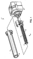
- Fig. 1 is an exploded view of a single-element heater according to a preferred embodiment of this invention.
- Fig. 2 is a cross-sectional view of the single-element heater of Fig. 1.
- Fig. 3 is an end view of the exit end of the single-element heater of Fig. 1.
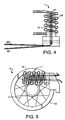
- FIG. 4 is an illustration of the inlet temperature sensing assembly of Fig. 1.
- FIG. 5 is an illustration of spatial relationship of the inlet temperature sensing assembly with respect to the heater element of Fig. 1 as viewed from the inlet end of the heater.
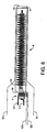
- FIG. 6 is an illustration of the temperature control system of the single-element heater shown in Fig. 1.
- FIG. 7 is a schematic illustration of a temperature control circuit for a heater according to this invention.
- FIG. 8 is an exploded view of a six-element heater according to an alternate embodiment of this invention.
- Fig. 9 is a cross sectional view of the assembled six-element heater shown in Fig. 8.
- Fig. 10 is a cut-away view of the ceramic tube and the exit thermocouple.
- FIG. 1 and 2 there is shown an exploded view of a single-element heater 1 according to a preferred embodiment of this invention.
- the heater 1 has a heater housing 3 and base 9 which provides electrical power and air inlet connections.
- a single heating element 8 is disposed within heater housing 3.
- the heater element 8 has element winding 5 which is contained within ceramic tube 12.
- the temperature control system for the heater comprises exit thermocouple 11 and inlet temperature sensing assembly 7.
- the thermocouple 11 is placed inside the ceramic tube 12 near the exit 14 of the heater element 8. This placement is better illustrated in Figs.
- thermocouple wire size should be selected to optimize the response time and the strength of the wire.
- the thermocouple wire preferably has a diameter of about 0.020". Heavier wire would have a slower response time and finer wire would not be as robust.
- the exit thermocouple is intended primarily to provide a temperature indication to be used to limit the maximum exit temperature and thereby prevent over-temperature operating conditions which will cause heater failure. This protection can be achieved by connecting this thermocouple to a simple relay output temperature controller to cut power before an over-temperature condition that could cause heater failure exists.
- the exit thermocouple can also be used to control the exit temperature of the heater. The operator can set a maximum temperature on their temperature controller. This thermocouple can also be used to trigger an alarm condition on the temperature controller which will provide burnout protection.
- An example of a temperature control circuit is shown in Fig. 7.
- Inlet temperature sensing assembly 7 containing inlet thermocouple 21 is located at the inlet end 16 of heater element 8.
- the inlet thermocouple 21 is shown mounted inside a coil 25 made of resistance wire and having a ceramic support 27. Electrical connections are provided by leads S2+ and S2-.
- the inlet temperature sensing assembly is oriented 90° to the central axis of heater element 8 and located at an offset position as shown in Figs. 3 and 5.
- the components of the temperature control system are shown in Fig. 6 in relation to heater element 8. Electrical leads S1 + and S1- run down the length of the ceramic tube 12 of heater element 8 to provide electrical connections to exit thermocouple 11. Electrical power to the heater element and the coil 25 of the inlet temperature sensing assembly 7 are provide by electrical leads L1 and L2.
- the function of the inlet thermocouple 21 is to provide burnout protection for the heater under conditions of low or no air flow. As air flow through the heater element 8 is reduced, the ability of the exit thermocouple 11 to accurately monitor the heater element temperature is greatly reduced. Under conditions of no air flow, the exit thermocouple will not be able to detect element temperature which will result in element burnout.
- By mounting the inlet thermocouple 21 inside a coil an area is created that will heat up when air flow is low or stops. During normal operation, the air will flow through the coil. Mounting the inlet thermocouple 21 inside coil 25 allows the coil/thermocouple to function independently of heater orientation. The coil is designed to have a low wattage so that the temperature inside the coil will increase only minimally under normal operating conditions.
- the inlet thermocouple When air flow is low or absent, the air inside the coil becomes heated and the inlet thermocouple inside the coil detects the temperature increase.
- the output from the inlet thermocouple is used to limit temperature inside the coil and thereby protect the heater element from burnout during low and no air flow conditions. Protection is achieved by connecting the inlet thermocouple to a over-temperature controller such as the one illustrated in Fig. 7.
- the temperature controllers send a DC pulse to activate the respective solid state relays (SSR) when the over temperature conditions are detected at either the inlet or the exit of the heater element. This disconnects the input electrical power to the heater to prevent failure of the heater element.
- SSR solid state relays
- the inlet temperature of the heater element will naturally be much lower than the exit temperature.
- the temperature inside the inlet temperature sensing assembly should be limited about 300°F and the temperature at the exit thermocouple should be limited to about 1400°F. These temperatures may be adjusted to accommodate various changes in heater configurations and heater elements as well as the desired degree of over-temperature protection.
- the exit thermocouple is Type K.
- the inlet thermocouple is preferably a Type J or a Type K because the inlet temperature is much lower. During normal operation there will be some overshoot, but in general the maximum temperature at the inlet thermocouple will be approximately 400°F. Using a Type K thermocouple to monitor both the inlet and exit temperatures makes it easier to set up the electronic controls.
- Figs. 8 and 9 illustrate an alternate embodiment of the heater according to this invention.
- heater 40 has six heater elements 8.
- the inlet temperature assembly 7 is again located at the inlet end of the heater elements and only one of the heater elements is fitted with an exit thermocouple 11.
Landscapes
- Engineering & Computer Science (AREA)
- Physics & Mathematics (AREA)
- Thermal Sciences (AREA)
- Chemical & Material Sciences (AREA)
- Combustion & Propulsion (AREA)
- Mechanical Engineering (AREA)
- General Engineering & Computer Science (AREA)
- General Physics & Mathematics (AREA)
- Fluid Mechanics (AREA)
- Direct Air Heating By Heater Or Combustion Gas (AREA)
- Control Of Resistance Heating (AREA)
- Resistance Heating (AREA)
Abstract
Description
- [Para 2] Standard hot-air heaters can overheat quickly leading to element failure, particularly under conditions of reduced or no air flow. Prior attempts at preventing element failure caused by over-temperature conditions involved attaching a thermocouple directly to the element winding, placing a thermistor in the preheater section of the element winding, or using an optical sensor to detect element temperature.
- [Para 3] The heater of this invention has a temperature sensing control system which can be used for both temperature control and over-temperature protection against element burnout. The temperature control system is comprised of an inlet temperature sensing assembly positioned at the inlet to the heater element and an exit thermocouple positioned in the exit end of the heater element. The exit thermocouple may be used for control the heater temperature and provide over-temperature protection. The inlet temperature sensing assembly is used to detect low or no air flow conditions which could lead to heater element failure.
- [Para 4] In one embodiment, the heater configuration will have a single element winding in a ceramic tube for single phase use. In another embodiment. the heater configuration has multiple heater elements comprised of multiple parallel element windings in multiple ceramic tubes for higher wattage single or three phase applications. Preferably, the multi-heater element embodiment has six heater elements. However, other numbers of heater elements are possible which allows for heater to be adapted to the needs of the user.
- [Para 5] Fig. 1 is an exploded view of a single-element heater according to a preferred embodiment of this invention.
- [Para 6] Fig. 2 is a cross-sectional view of the single-element heater of Fig. 1.
- [Para 7] Fig. 3 is an end view of the exit end of the single-element heater of Fig. 1.
- [Para 8] Fig. 4 is an illustration of the inlet temperature sensing assembly of Fig. 1.
- [Para 9] Fig. 5 is an illustration of spatial relationship of the inlet temperature sensing assembly with respect to the heater element of Fig. 1 as viewed from the inlet end of the heater.
- [Para 10] Fig. 6 is an illustration of the temperature control system of the single-element heater shown in Fig. 1.
- [Para 11] Fig. 7 is a schematic illustration of a temperature control circuit for a heater according to this invention.
- [Para 12] Fig. 8 is an exploded view of a six-element heater according to an alternate embodiment of this invention.
- [Para 13] Fig. 9 is a cross sectional view of the assembled six-element heater shown in Fig. 8.
- [Para 14] Fig. 10 is a cut-away view of the ceramic tube and the exit thermocouple.
- [Para 15] For a better understanding of the present invention, together with other and further objects, advantages and capabilities thereof, reference is made to the following disclosure and appended claims taken in conjunction with the above-described drawings.[Para 16] Referring to Figs. 1 and 2, there is shown an exploded view of a single-
element heater 1 according to a preferred embodiment of this invention. Theheater 1 has aheater housing 3 andbase 9 which provides electrical power and air inlet connections. Asingle heating element 8 is disposed withinheater housing 3. Theheater element 8 has element winding 5 which is contained withinceramic tube 12. The temperature control system for the heater comprisesexit thermocouple 11 and inlet temperature sensing assembly 7. Thethermocouple 11 is placed inside theceramic tube 12 near theexit 14 of theheater element 8. This placement is better illustrated in Figs. 2 and 10. Preferably, aslot 51 is cut in the ceramic tube so that the thermocouple can be in close proximity to the element winding. A thermocouple placed in this location provides faster response than a thermocouple attached to theexit 19 of the heater housing. Fast response is required for heaters having a fast response of the heater element winding. Without a fast thermocouple response, the heater element winding can overheat before the control thermocouple has reacted to a temperature increase. Fast response heaters are heaters where the time constant of the heater is as fast or faster than the time constant of the thermocouple. The time constant will vary depending on the air flow, heater wattage and set point temperature. Response times are generally in the range of 5 to 15 seconds for both the thermocouples and the heater elements. The thermocouple wire size should be selected to optimize the response time and the strength of the wire. Preferably, the thermocouple wire preferably has a diameter of about 0.020". Heavier wire would have a slower response time and finer wire would not be as robust. - [Para 17] The exit thermocouple is intended primarily to provide a temperature indication to be used to limit the maximum exit temperature and thereby prevent over-temperature operating conditions which will cause heater failure. This protection can be achieved by connecting this thermocouple to a simple relay output temperature controller to cut power before an over-temperature condition that could cause heater failure exists. The exit thermocouple can also be used to control the exit temperature of the heater. The operator can set a maximum temperature on their temperature controller. This thermocouple can also be used to trigger an alarm condition on the temperature controller which will provide burnout protection. An example of a temperature control circuit is shown in Fig. 7.
- [Para 18] Inlet temperature sensing assembly 7 containing
inlet thermocouple 21 is located at theinlet end 16 ofheater element 8. Referring to Fig. 4, theinlet thermocouple 21 is shown mounted inside acoil 25 made of resistance wire and having aceramic support 27. Electrical connections are provided by leads S2+ and S2-. Preferably, the inlet temperature sensing assembly is oriented 90° to the central axis ofheater element 8 and located at an offset position as shown in Figs. 3 and 5. The components of the temperature control system are shown in Fig. 6 in relation toheater element 8. Electrical leads S1 + and S1- run down the length of theceramic tube 12 ofheater element 8 to provide electrical connections to exitthermocouple 11. Electrical power to the heater element and thecoil 25 of the inlet temperature sensing assembly 7 are provide by electrical leads L1 and L2. - [Para 19] The function of the
inlet thermocouple 21 is to provide burnout protection for the heater under conditions of low or no air flow. As air flow through theheater element 8 is reduced, the ability of theexit thermocouple 11 to accurately monitor the heater element temperature is greatly reduced. Under conditions of no air flow, the exit thermocouple will not be able to detect element temperature which will result in element burnout. By mounting theinlet thermocouple 21 inside a coil, an area is created that will heat up when air flow is low or stops. During normal operation, the air will flow through the coil. Mounting theinlet thermocouple 21 insidecoil 25 allows the coil/thermocouple to function independently of heater orientation. The coil is designed to have a low wattage so that the temperature inside the coil will increase only minimally under normal operating conditions. When air flow is low or absent, the air inside the coil becomes heated and the inlet thermocouple inside the coil detects the temperature increase. The output from the inlet thermocouple is used to limit temperature inside the coil and thereby protect the heater element from burnout during low and no air flow conditions. Protection is achieved by connecting the inlet thermocouple to a over-temperature controller such as the one illustrated in Fig. 7. The temperature controllers send a DC pulse to activate the respective solid state relays (SSR) when the over temperature conditions are detected at either the inlet or the exit of the heater element. This disconnects the input electrical power to the heater to prevent failure of the heater element. - [Para 20] The inlet temperature of the heater element will naturally be much lower than the exit temperature. In a preferred embodiment, the temperature inside the inlet temperature sensing assembly should be limited about 300°F and the temperature at the exit thermocouple should be limited to about 1400°F. These temperatures may be adjusted to accommodate various changes in heater configurations and heater elements as well as the desired degree of over-temperature protection. Preferably, the exit thermocouple is Type K. The inlet thermocouple is preferably a Type J or a Type K because the inlet temperature is much lower. During normal operation there will be some overshoot, but in general the maximum temperature at the inlet thermocouple will be approximately 400°F. Using a Type K thermocouple to monitor both the inlet and exit temperatures makes it easier to set up the electronic controls.
- [Para 21] Figs. 8 and 9 illustrate an alternate embodiment of the heater according to this invention. In this case,
heater 40 has sixheater elements 8. The inlet temperature assembly 7 is again located at the inlet end of the heater elements and only one of the heater elements is fitted with anexit thermocouple 11. - [Para 22] While there has been shown and described what are at the present considered the preferred embodiments of the invention, it will be obvious to those skilled in the art that various changes and modifications may be made therein without departing from the scope of the invention as defined by the appended claims.
Claims (18)
- A heater comprising: a temperature control system and a heater element disposed in a heater housing, the temperature control system comprising an inlet temperature sensing assembly and an exit thermocouple, the exit thermocouple being positioned at an exit end of the heater element, the inlet temperature sensing assembly being positioned at an inlet end of the heater element, and the inlet temperature assembly comprising a resistive coil and an inlet thermocouple disposed within the coil.
- The heater of claim 1 wherein the inlet thermocouple and the exit thermocouple are each connected to a respective temperature controller that activates a relay when a maximum temperature condition is sensed, the relay when activated disconnecting electrical power to the heater element.
- The heater of claim 1 wherein the heater element and the resistive coil are connected in series.
- The heater of claim 1 wherein the resistive coil is wound around a ceramic support.
- The heater of claim 1 wherein the heater element has a central axis and the inlet temperature assembly is oriented 90° to the central axis of the heater element.
- The heater of claim 1 wherein the heater element has a central axis and the inlet temperature assembly is offset from the central axis of the heater element.
- The heater of claim 1 wherein the thermocouples and the heater element have a response time in the range of 5 to 15 seconds.
- The heater of claim 1 wherein the heater element comprises a ceramic tube containing an element winding, the ceramic tube having slots in an end to receive the exit thermocouple.
- A heater comprising: a temperature control system and a heater element disposed in a heater housing, the temperature control system comprising an inlet temperature sensing assembly and an exit thermocouple, the exit thermocouple being positioned at an exit end of the heater element, the inlet temperature sensing assembly being positioned at an inlet end of the heater element whereby the inlet temperature sensing assembly detects a low or no air flow condition and the exit thermocouple detects an exit temperature of the heater element.
- A heater comprising:a temperature control system and a heater element disposed in a heater housing;the heater element having a central axis and comprising a ceramic tube containing an element winding;the temperature control system comprising an inlet temperature sensing assembly and an exit thermocouple, the exit thermocouple being positioned at an exit end of the heater element adjacent to the element winding, the inlet temperature sensing assembly being positioned at an inlet end of the heater element at an offset from the central axis, and the inlet temperature assembly comprising a resistive coil wound around a ceramic support and an inlet thermocouple disposed within the coil.
- A temperature control system for a heater having a heater element, the temperature control system comprising an exit thermocouple positioned at an exit end of the heater element and an inlet temperature sensing assembly positioned at an inlet end of the heater element, the inlet temperature sensing assembly having a heated inlet thermocouple, the inlet thermocouple and the exit thermocouple each being connected to a respective temperature controller that activates a relay when a maximum temperature condition is sensed, the relay when activated disconnecting electrical power to the heater element.
- The temperature control system of claim 11 wherein the inlet thermocouple is disposed within a resistive coil.
- The temperature control system of claim 11 wherein the inlet thermocouple is used to detect a low or no air flow condition within the heater and the exit thermocouple is used to control an exit temperature of the heater element.
- A method of controlling a heater, comprising:(a) sensing an exit temperature of the heater with an exit thermocouple connected to a first temperature controller;(b) sensing air flow into an inlet end of the heater with a heated inlet thermocouple connected to a second temperature controller;(c) generating a first signal from the first temperature controller to a first relay when a maximum exit temperature is sensed, the first signal activating the first relay whereby electrical power to the heater is disconnected; and(d) generating a second signal from the second temperature controller to a second relay when a low or no air flow condition is sensed whereby electrical power to the heater is disconnected.
- The method of claim 14 wherein an alarm is activated when the maximum exit temperature is sensed.
- The method of claim 14 wherein a low or no air flow condition causes a temperature increase that is sensed by the inlet thermocouple.
- The method of claim 14 wherein the first signal is generated when the exit thermocouple senses a temperature of about 1400°F.
- The method of claim 14 wherein the second signal is generated when the inlet thermocouple senses a temperature of about 300°F.
Applications Claiming Priority (2)
| Application Number | Priority Date | Filing Date | Title |
|---|---|---|---|
| US52270504P | 2004-10-29 | 2004-10-29 | |
| US11/161,829 US7180039B2 (en) | 2004-10-29 | 2005-08-18 | Heater with burnout protection |
Publications (2)
| Publication Number | Publication Date |
|---|---|
| EP1653165A1 true EP1653165A1 (en) | 2006-05-03 |
| EP1653165B1 EP1653165B1 (en) | 2012-01-25 |
Family
ID=35483501
Family Applications (1)
| Application Number | Title | Priority Date | Filing Date |
|---|---|---|---|
| EP05023698A Expired - Lifetime EP1653165B1 (en) | 2004-10-29 | 2005-10-28 | Heater with burnout protection |
Country Status (3)
| Country | Link |
|---|---|
| US (1) | US7180039B2 (en) |
| EP (1) | EP1653165B1 (en) |
| JP (1) | JP4959172B2 (en) |
Cited By (11)
| Publication number | Priority date | Publication date | Assignee | Title |
|---|---|---|---|---|
| WO2008125875A2 (en) | 2007-04-13 | 2008-10-23 | Basic Device Limited | Radiators |
| WO2011066019A3 (en) * | 2009-11-30 | 2011-07-21 | Emerson Electric Co. | Flow-through heater |
| US8182233B2 (en) | 2007-07-13 | 2012-05-22 | Rolls-Royce Plc | Component with a damping filler |
| US8241004B2 (en) | 2008-05-15 | 2012-08-14 | Rolls-Royce, Plc | Component structure |
| US8365388B2 (en) | 2009-01-28 | 2013-02-05 | Rolls-Royce Plc | Method of joining plates of material to form a structure |
| US8529720B2 (en) | 2008-07-24 | 2013-09-10 | Rolls-Royce, Plc | Aerofoil sub-assembly, an aerofoil and a method of making an aerofoil |
| US8701286B2 (en) | 2010-06-02 | 2014-04-22 | Rolls-Royce Plc | Rotationally balancing a rotating part |
| US8920893B2 (en) | 2009-01-27 | 2014-12-30 | Rolls-Royce Plc | Article with an internal structure |
| US8986490B2 (en) | 2010-11-26 | 2015-03-24 | Rolls-Royce Plc | Method of manufacturing a component |
| CN112629033A (en) * | 2019-09-24 | 2021-04-09 | 广东芬尼克兹节能设备有限公司 | Low-flow protection control method, device, equipment and storage medium for water heater |
| DE102022117782A1 (en) | 2022-07-15 | 2024-01-18 | Otto Junker Gesellschaft mit beschränkter Haftung | System and use of a thermocouple to monitor the temperature of a heating element |
Families Citing this family (7)
| Publication number | Priority date | Publication date | Assignee | Title |
|---|---|---|---|---|
| US9137858B2 (en) * | 2007-12-10 | 2015-09-15 | Sandvik Intellectual Property Ab | Electric heating device |
| ATE492140T1 (en) * | 2008-06-09 | 2011-01-15 | Leister Process Tech | ELECTRICAL RESISTANCE HEATING ELEMENT FOR A HEATING DEVICE FOR HEATING A FLOWING GASEOUS MEDIUM |
| US20120168143A1 (en) * | 2010-12-30 | 2012-07-05 | Poole Ventura, Inc. | Thermal Diffusion Chamber With Heat Exchanger |
| CN103791787A (en) * | 2013-11-25 | 2014-05-14 | 邵建军 | Temperature reaming device for cast explosives |
| US10736180B2 (en) | 2017-04-28 | 2020-08-04 | Tutco Llc | Heater with an optical sensor for over-temperature protection |
| CN109405309A (en) * | 2018-10-30 | 2019-03-01 | 重庆三峡学院 | Temperature automatically controlled hot water apparatus |
| CN119289526A (en) * | 2023-07-10 | 2025-01-10 | 浙江普莱得电器股份有限公司 | A method for handling abnormal temperature of a hot air heating device |
Citations (4)
| Publication number | Priority date | Publication date | Assignee | Title |
|---|---|---|---|---|
| WO1984003552A1 (en) | 1983-03-07 | 1984-09-13 | Skilten Electronics | Heated gas blower device |
| US5111527A (en) | 1990-03-12 | 1992-05-05 | Gte Products Corporation | Electric heater with thermistor temperature control |
| US5805767A (en) * | 1996-01-16 | 1998-09-08 | Jouas; Gary | Electronically-controlled heater |
| US20030016953A1 (en) * | 2001-07-19 | 2003-01-23 | Wilson Bradley J. | Electric heater with dual overheat limits |
Family Cites Families (11)
| Publication number | Priority date | Publication date | Assignee | Title |
|---|---|---|---|---|
| US3393101A (en) * | 1965-06-29 | 1968-07-16 | Gen Motors Corp | Thermocouple probe with plural junctions |
| US3551643A (en) * | 1967-10-12 | 1970-12-29 | Sylvania Electric Prod | Electric heater for heating fluids flowing longitudinally therethrough |
| US3724261A (en) * | 1971-08-31 | 1973-04-03 | Gen Electric | Device for measuring heat release in continuous calorimeter |
| US4314143A (en) * | 1979-06-29 | 1982-02-02 | Baxter Travenol Laboratories, Inc. | Blood warming apparatus with digital display and monitoring circuit |
| NZ201460A (en) * | 1981-08-17 | 1986-11-12 | Allware Agencies Ltd | Multipurpose microprocessor controlled heating and cooling fan |
| US5666929A (en) * | 1995-06-07 | 1997-09-16 | Tyma, Inc. | Fuel vaporizer for an internal combustion engine |
| US6131570A (en) * | 1998-06-30 | 2000-10-17 | Aradigm Corporation | Temperature controlling device for aerosol drug delivery |
| JP4074741B2 (en) * | 2000-09-01 | 2008-04-09 | 富士フイルム株式会社 | Fluid heating supply device |
| EP1233650B1 (en) * | 2001-01-24 | 2006-08-09 | Leister Process Technologies | Hot air device |
| JP3988942B2 (en) * | 2003-03-31 | 2007-10-10 | 株式会社国際電気セミコンダクターサービス | Heater inspection apparatus and semiconductor manufacturing apparatus equipped with the same |
| US7012223B2 (en) * | 2003-11-25 | 2006-03-14 | National Environmental Products, Ltd. | Forced-air heater control system and method |
-
2005
- 2005-08-18 US US11/161,829 patent/US7180039B2/en not_active Expired - Lifetime
- 2005-10-28 EP EP05023698A patent/EP1653165B1/en not_active Expired - Lifetime
- 2005-10-28 JP JP2005314420A patent/JP4959172B2/en not_active Expired - Lifetime
Patent Citations (4)
| Publication number | Priority date | Publication date | Assignee | Title |
|---|---|---|---|---|
| WO1984003552A1 (en) | 1983-03-07 | 1984-09-13 | Skilten Electronics | Heated gas blower device |
| US5111527A (en) | 1990-03-12 | 1992-05-05 | Gte Products Corporation | Electric heater with thermistor temperature control |
| US5805767A (en) * | 1996-01-16 | 1998-09-08 | Jouas; Gary | Electronically-controlled heater |
| US20030016953A1 (en) * | 2001-07-19 | 2003-01-23 | Wilson Bradley J. | Electric heater with dual overheat limits |
Cited By (15)
| Publication number | Priority date | Publication date | Assignee | Title |
|---|---|---|---|---|
| WO2008125875A2 (en) | 2007-04-13 | 2008-10-23 | Basic Device Limited | Radiators |
| US9022299B2 (en) | 2007-04-13 | 2015-05-05 | Basic Device Limited | Radiators |
| US8182233B2 (en) | 2007-07-13 | 2012-05-22 | Rolls-Royce Plc | Component with a damping filler |
| US8857054B2 (en) | 2007-07-13 | 2014-10-14 | Rolls-Royce Plc | Method of forming an aerofoil with a damping filler |
| US8381398B2 (en) | 2007-07-13 | 2013-02-26 | Rolls-Royce Plc | Component with a damping filler and method |
| US8241004B2 (en) | 2008-05-15 | 2012-08-14 | Rolls-Royce, Plc | Component structure |
| US8529720B2 (en) | 2008-07-24 | 2013-09-10 | Rolls-Royce, Plc | Aerofoil sub-assembly, an aerofoil and a method of making an aerofoil |
| US8920893B2 (en) | 2009-01-27 | 2014-12-30 | Rolls-Royce Plc | Article with an internal structure |
| US8365388B2 (en) | 2009-01-28 | 2013-02-05 | Rolls-Royce Plc | Method of joining plates of material to form a structure |
| WO2011066019A3 (en) * | 2009-11-30 | 2011-07-21 | Emerson Electric Co. | Flow-through heater |
| US8701286B2 (en) | 2010-06-02 | 2014-04-22 | Rolls-Royce Plc | Rotationally balancing a rotating part |
| US8986490B2 (en) | 2010-11-26 | 2015-03-24 | Rolls-Royce Plc | Method of manufacturing a component |
| CN112629033A (en) * | 2019-09-24 | 2021-04-09 | 广东芬尼克兹节能设备有限公司 | Low-flow protection control method, device, equipment and storage medium for water heater |
| CN112629033B (en) * | 2019-09-24 | 2022-05-27 | 广东芬尼克兹节能设备有限公司 | Low-flow protection control method, device, equipment and storage medium for water heater |
| DE102022117782A1 (en) | 2022-07-15 | 2024-01-18 | Otto Junker Gesellschaft mit beschränkter Haftung | System and use of a thermocouple to monitor the temperature of a heating element |
Also Published As
| Publication number | Publication date |
|---|---|
| JP2006138625A (en) | 2006-06-01 |
| US20060091132A1 (en) | 2006-05-04 |
| JP4959172B2 (en) | 2012-06-20 |
| US7180039B2 (en) | 2007-02-20 |
| EP1653165B1 (en) | 2012-01-25 |
Similar Documents
| Publication | Publication Date | Title |
|---|---|---|
| US7180039B2 (en) | Heater with burnout protection | |
| KR102165329B1 (en) | Heater system including heater bundle for adaptive control and control method thereof | |
| US6222162B1 (en) | Electric blanket and control | |
| US4208570A (en) | Thermostatically controlled electric engine coolant heater | |
| US6150641A (en) | Temperature sensing and limiting device | |
| US5212763A (en) | Electric fluid heater with infrared hot spot sensor | |
| KR100886662B1 (en) | Temperature controller and the method using Double Timing Signal | |
| US6169850B1 (en) | Air heating device | |
| US5111527A (en) | Electric heater with thermistor temperature control | |
| CN103119681B (en) | By the electronic thermostat of resistance clean boot | |
| EP0726693A1 (en) | Heater for aquarium fish tank | |
| KR101057519B1 (en) | Ultra-compact Thermal Control Unit with Surface-Mount Temperature Sensor | |
| JPH09184771A (en) | Sensor for detecting overheat of water heater | |
| JPH0560415U (en) | Temperature sensor for cooker | |
| KR0166254B1 (en) | How to detect disconnection and poor contact of heater thermistor | |
| FI62612C (en) | ANORDINATION FOR TEMPERATURBEGRAENSING IN CHANNELS | |
| KR100376330B1 (en) | Thermistor controller of medical heating machine | |
| EP3690549B1 (en) | Fixing device | |
| KR100840601B1 (en) | Temperature sensor and heating system using it | |
| EP2226698A2 (en) | A thermostat for white goods | |
| JP2626260B2 (en) | Electric heater | |
| CA3235831A1 (en) | Gas heater | |
| JPH10318852A (en) | Overheat detection temperature sensor with fuse function | |
| JPH04110526A (en) | Temperature regulating device for floor heater | |
| WO2024184723A1 (en) | Heater for a hand held appliance |
Legal Events
| Date | Code | Title | Description |
|---|---|---|---|
| PUAI | Public reference made under article 153(3) epc to a published international application that has entered the european phase |
Free format text: ORIGINAL CODE: 0009012 |
|
| AK | Designated contracting states |
Kind code of ref document: A1 Designated state(s): AT BE BG CH CY CZ DE DK EE ES FI FR GB GR HU IE IS IT LI LT LU LV MC NL PL PT RO SE SI SK TR |
|
| AX | Request for extension of the european patent |
Extension state: AL BA HR MK YU |
|
| RIN1 | Information on inventor provided before grant (corrected) |
Inventor name: AROLD, JONATHAN B. Inventor name: FRAPPIER, MICHAEL J. Inventor name: STARK, JOSEPH P. Inventor name: GOSSELIN, WILLIAM H. |
|
| 17P | Request for examination filed |
Effective date: 20060609 |
|
| 17Q | First examination report despatched |
Effective date: 20060717 |
|
| AKX | Designation fees paid |
Designated state(s): DE IT SE |
|
| RAP1 | Party data changed (applicant data changed or rights of an application transferred) |
Owner name: OSRAM SYLVANIA INC. |
|
| GRAP | Despatch of communication of intention to grant a patent |
Free format text: ORIGINAL CODE: EPIDOSNIGR1 |
|
| GRAS | Grant fee paid |
Free format text: ORIGINAL CODE: EPIDOSNIGR3 |
|
| GRAA | (expected) grant |
Free format text: ORIGINAL CODE: 0009210 |
|
| AK | Designated contracting states |
Kind code of ref document: B1 Designated state(s): DE IT SE |
|
| REG | Reference to a national code |
Ref country code: DE Ref legal event code: R081 Ref document number: 602005032357 Country of ref document: DE Owner name: TUTCO, LLC, COOKEVILLE, US Free format text: FORMER OWNER: OSRAM SYLVANIA INC., DANVERS, MASS., US |
|
| REG | Reference to a national code |
Ref country code: DE Ref legal event code: R096 Ref document number: 602005032357 Country of ref document: DE Effective date: 20120322 |
|
| REG | Reference to a national code |
Ref country code: SE Ref legal event code: TRGR |
|
| PLBE | No opposition filed within time limit |
Free format text: ORIGINAL CODE: 0009261 |
|
| STAA | Information on the status of an ep patent application or granted ep patent |
Free format text: STATUS: NO OPPOSITION FILED WITHIN TIME LIMIT |
|
| 26N | No opposition filed |
Effective date: 20121026 |
|
| REG | Reference to a national code |
Ref country code: DE Ref legal event code: R097 Ref document number: 602005032357 Country of ref document: DE Effective date: 20121026 |
|
| REG | Reference to a national code |
Ref country code: DE Ref legal event code: R082 Ref document number: 602005032357 Country of ref document: DE Ref country code: DE Ref legal event code: R081 Ref document number: 602005032357 Country of ref document: DE Owner name: TUTCO, LLC, COOKEVILLE, US Free format text: FORMER OWNER: OSRAM SYLVANIA INC., DANVERS, MASS., US |
|
| PGFP | Annual fee paid to national office [announced via postgrant information from national office to epo] |
Ref country code: SE Payment date: 20240910 Year of fee payment: 20 Ref country code: IT Payment date: 20240910 Year of fee payment: 20 |
|
| PGFP | Annual fee paid to national office [announced via postgrant information from national office to epo] |
Ref country code: DE Payment date: 20240904 Year of fee payment: 20 |
|
| REG | Reference to a national code |
Ref country code: DE Ref legal event code: R071 Ref document number: 602005032357 Country of ref document: DE |
|
| REG | Reference to a national code |
Ref country code: SE Ref legal event code: EUG |