EP1653086A1 - Vacuum pump - Google Patents
Vacuum pump Download PDFInfo
- Publication number
- EP1653086A1 EP1653086A1 EP04748202A EP04748202A EP1653086A1 EP 1653086 A1 EP1653086 A1 EP 1653086A1 EP 04748202 A EP04748202 A EP 04748202A EP 04748202 A EP04748202 A EP 04748202A EP 1653086 A1 EP1653086 A1 EP 1653086A1
- Authority
- EP
- European Patent Office
- Prior art keywords
- vacuum pump
- pump
- stator
- rotor
- cooling water
- Prior art date
- Legal status (The legal status is an assumption and is not a legal conclusion. Google has not performed a legal analysis and makes no representation as to the accuracy of the status listed.)
- Granted
Links
Images




Classifications
-
- F—MECHANICAL ENGINEERING; LIGHTING; HEATING; WEAPONS; BLASTING
- F04—POSITIVE - DISPLACEMENT MACHINES FOR LIQUIDS; PUMPS FOR LIQUIDS OR ELASTIC FLUIDS
- F04D—NON-POSITIVE-DISPLACEMENT PUMPS
- F04D19/00—Axial-flow pumps
- F04D19/02—Multi-stage pumps
- F04D19/04—Multi-stage pumps specially adapted to the production of a high vacuum, e.g. molecular pumps
-
- F—MECHANICAL ENGINEERING; LIGHTING; HEATING; WEAPONS; BLASTING
- F04—POSITIVE - DISPLACEMENT MACHINES FOR LIQUIDS; PUMPS FOR LIQUIDS OR ELASTIC FLUIDS
- F04D—NON-POSITIVE-DISPLACEMENT PUMPS
- F04D19/00—Axial-flow pumps
- F04D19/02—Multi-stage pumps
- F04D19/04—Multi-stage pumps specially adapted to the production of a high vacuum, e.g. molecular pumps
- F04D19/042—Turbomolecular vacuum pumps
-
- F—MECHANICAL ENGINEERING; LIGHTING; HEATING; WEAPONS; BLASTING
- F04—POSITIVE - DISPLACEMENT MACHINES FOR LIQUIDS; PUMPS FOR LIQUIDS OR ELASTIC FLUIDS
- F04C—ROTARY-PISTON, OR OSCILLATING-PISTON, POSITIVE-DISPLACEMENT MACHINES FOR LIQUIDS; ROTARY-PISTON, OR OSCILLATING-PISTON, POSITIVE-DISPLACEMENT PUMPS
- F04C25/00—Adaptations of pumps for special use of pumps for elastic fluids
- F04C25/02—Adaptations of pumps for special use of pumps for elastic fluids for producing high vacuum
-
- F—MECHANICAL ENGINEERING; LIGHTING; HEATING; WEAPONS; BLASTING
- F04—POSITIVE - DISPLACEMENT MACHINES FOR LIQUIDS; PUMPS FOR LIQUIDS OR ELASTIC FLUIDS
- F04D—NON-POSITIVE-DISPLACEMENT PUMPS
- F04D25/00—Pumping installations or systems
- F04D25/02—Units comprising pumps and their driving means
- F04D25/06—Units comprising pumps and their driving means the pump being electrically driven
-
- F—MECHANICAL ENGINEERING; LIGHTING; HEATING; WEAPONS; BLASTING
- F04—POSITIVE - DISPLACEMENT MACHINES FOR LIQUIDS; PUMPS FOR LIQUIDS OR ELASTIC FLUIDS
- F04D—NON-POSITIVE-DISPLACEMENT PUMPS
- F04D29/00—Details, component parts, or accessories
- F04D29/58—Cooling; Heating; Diminishing heat transfer
- F04D29/5806—Cooling the drive system
-
- F—MECHANICAL ENGINEERING; LIGHTING; HEATING; WEAPONS; BLASTING
- F04—POSITIVE - DISPLACEMENT MACHINES FOR LIQUIDS; PUMPS FOR LIQUIDS OR ELASTIC FLUIDS
- F04D—NON-POSITIVE-DISPLACEMENT PUMPS
- F04D29/00—Details, component parts, or accessories
- F04D29/58—Cooling; Heating; Diminishing heat transfer
- F04D29/582—Cooling; Heating; Diminishing heat transfer specially adapted for elastic fluid pumps
- F04D29/584—Cooling; Heating; Diminishing heat transfer specially adapted for elastic fluid pumps cooling or heating the machine
Definitions
- the present invention relates to a vacuum pump used for semiconductor manufacturing apparatus and, more particularly, to a vacuum pump in which a cooling water pipe is buried in the wall of a stator column.
- a vacuum pump is used as a means for exhausting the gas in the process chamber to generate a high vacuum in the process chamber.
- vacuum pump various types of pumps such as a turbo-molecular pump and a thread groove pump are available.
- a turbo-molecular pump As the vacuum pump, various types of pumps such as a turbo-molecular pump and a thread groove pump are available.
- a conventional vacuum pump a composite vacuum pump in which a turbo-molecular pump and a thread groove pump are compounded is used.
- rotating blades and stationary blades provided in multiple stages on the upper inner peripheral surface of a pump case function as a turbo-molecular pump by means of the rotation of a rotor.
- a turbo-molecular pump By the function of the turbo-molecular pump, a downward momentum is given to the introduced gas, and the gas is transferred to the exhaust side.
- a thread groove and the rotor function as a thread groove pump by means of the rotation of the rotor.
- gas is compressed from an intermediate flow to a viscous flow and transferred to the gas discharge port side (for example, refer to Patent Document 1).
- a stator column 502a is erected on the upper surface of a base 502b.
- an electrical equipment section consisting of a drive motor 503a and magnetic bearings 503b is disposed, and also a rotor 501 projecting from the interior of the stator column 502a is provided.
- the rotor 501 is rotatably held by the magnetic bearings 503b, and is rotated by the drive motor 503a.
- rotating blades 506 are provided in multiple stages. These rotating blades 506 and stationary blades 507 provided in multiple stages on the upper inner peripheral surface of the vacuum pump 500 function as a turbo-molecular pump by means of the rotation of the rotor 501. By this turbo-molecular pump, a downward momentum is given to the introduced gas, and the gas is transferred to the exhaust side.
- a thread stator 508 is provided, and at a position where the thread stator 508 faces to the lower outer periphery of the rotor 501, a thread groove 508a is formed.
- the thread groove 508a and the rotor 501 function as a thread groove pump by means of the rotation of the rotor 501.
- gas is compressed from an intermediate flow to a viscous flow and transferred to the gas discharge port side.
- the vacuum pump 500 since the electrical equipment section consisting of the drive motor 503a and magnetic bearings 503b is allowed to function by electric power, heat is produced in the electrical equipment section. Due to the produced heat, the vacuum pump 500 has a fear that the drive motor 503a is burned and the magnetic bearings 503b are destroyed.
- the configuration has been such that a cooling water pipe 504 is installed on the outside of the vacuum pump 500, on the lower surface of the stator column 502a, and on the outside of the base 502b, and cooling water or a refrigerant, such as a liquid or a gas, having a strong heat exchanging action is allowed to flow to cool the electrical equipment section (for example, refer to Patent Document 2).
- a cooling water pipe 504 is installed on the outside of the vacuum pump 500, on the lower surface of the stator column 502a, and on the outside of the base 502b, and cooling water or a refrigerant, such as a liquid or a gas, having a strong heat exchanging action is allowed to flow to cool the electrical equipment section (for example, refer to Patent Document 2).
- the cooling water pipe 504 is installed on the outside of the vacuum pump 500 and on the outside of the stator column 502a, the electrical equipment section and the cooling water pipe 504 are greatly separated from each other.
- the drive motor 503a having the greatest heat generating effect among the electrical equipment section is arranged approximately in the center of the vacuum pump 500, so that it is greatly separated from the cooling water pipe 504. If the electrical equipment section and the cooling water pipe 504 are separated greatly from each other, a loss of cooling effect occurs during the time when the cooling effect of the cooling water pipe 504 reaches the electrical equipment section, so that the electrical equipment section cannot be cooled effectively.
- the cooling effect can be allowed to reach the electrical equipment section even if the loss of cooling effect occurs. In this case, however, the cooling effect also reaches a gas flow path, for example, in the thread stator 508 other than the electrical equipment section, so that there is a danger that the liquefaction or solidification of gas is promoted, and hence gas molecules are deposited in the vacuum pump 500.
- the deposition of gas molecules is considered, there is a limit to the increase in cooling force of the cooling water pipe 504. Consequently, in the case where the cooling water pipe 504 is installed on the outside of the vacuum pump 500, on the lower surface of the stator column 502a, and on the outside of the base 502b, it is difficult to cool the electrical equipment section with high efficiency.
- the rotor and the rotating blades are rotated at a high speed to exhaust the gas in the process chamber, and the rotating blades and the rotor produce frictional heat and compression heat with respect to the gas flow, so that the rotating blades and the rotor have an abnormally high temperature which may exceed the heat-resisting temperature. Therefore, in order to depress the rise in temperatures of the rotating blades and the rotor, the stator column is cooled, and hence the heat of the rotor and the rotating blades is absorbed by the cooled stator column.
- the above-described method namely, the method in which the cooling water pipe 504 is installed on the outer surface of the base 502b, and by installing this cooling water pipe 504, the cooling effect of the cooling water pipe 504 is allowed to reach the upper part of the stator column 502a via the base 502b, or the method in which the cooling water pipe is installed on the bottom surface of the stator column 502a, and the cooling effect of the cooling water pipe is allowed to reach from the bottom surface to the top surface.
- the cooling effect of the cooling water pipe 504 decreases in the upper part of the stator column 502a, especially near the lower stages of the rotating blades 506.
- the cooling effect can be allowed to reach the stator column 502a by increasing the cooling capacity of the cooling water pipe 504. However, if the cooling capacity of the cooling water pipe 504 is increased, the cooling effect also propagates, for example, to the thread stator 508, and hence gas molecules deposit in the thread groove 508a depending on the semiconductor manufacturing process.
- stator column 502a In order to absorb the heat on the rotor 501 side by means of the cooled stator column 502a, it is preferable that the stator column 502a be placed as close as possible to the inner peripheral surface of the rotor 501.
- the shape of the outer peripheral surface of the stator column 502a has been almost the same as the shape of the inner peripheral surface of the rotor 501.
- the shape of the rotor 501 is different, the shape of the stator column 502a is also different, and hence the shape of the rotor 502a is different from vacuum pump to vacuum pump.
- the bore of a pump case 509, the size of the base 502b supporting the pump case 509, the shape of the rotor 501, the shape of the stator column 502a, the length and width of the rotating blade 506, and the number of stages in which the rotating blades 506 are disposed are also different from vacuum pump to vacuum pump. The same is true for a vacuum pump of the same mechanism.
- Vacuum pumps 600 and 700 shown in Figures 8 (a) and 8 (b) are composite pumps in which a turbo-molecular pump and a thread groove pump are compounded.
- the lower side of a pump case 609, 709 is supported by a base 602b, 702b, by which an external casing is formed by the pump case 609, 709 and the base 602b, 702b.
- the sizes of the pump case 609, 709 and the base 602b, 702b are substantially regulated for each type of vacuum pump 600, 700.
- a rotor 601, 701 is disposed, and is rotatably supported by a stator column 602a, 702a erected on the upper surface of the base 602b, 702b.
- the rotor 601, 701 has a shape such as to cover the stator column 602a, 702a, and is placed as close as possible to the stator column 602a, 702a.
- the shape of the rotor 601, 701 is substantially regulated for each vacuum pump.
- the shape of the inner peripheral surface of the rotor 601, 701 is made almost the same as the shape of the outer peripheral surface of the stator column 602a, 702a, so that the shape of the stator column 602a, 702a is also substantially regulated for each vacuum pump.
- rotating blades 606, 706 are provided in multiple stages. As shown in Figures 8(a) and 8(b), the rotating blades 606, 706 provided in multiple stages have different length and width for each stage. Also, as shown in Figures 8 (a) and 8 (b), even in the vacuum pump of the same mechanism, the length and width of the rotating blade 606, 706 are different, and further the number of stages is also different.
- a thread pump stator 608, 708 On the lower inner peripheral surface of the pump case 609, 709, a thread pump stator 608, 708 abuts, and a thread groove 608a, 708a is formed in the inner peripheral surface of the thread pump stator 608, 708, namely, in the surface facing to the lower outer periphery of the rotor 601, 701.
- a cooling water pipe 604A, 704A is installed on the outer surface of the base 602b, 702b. Also, the cooling water pipe is sometimes installed on the bottom surface of the stator column 602a, 702a depending on the vacuum pump. In the cooling water pipe 604A, 704A, cooling water or a refrigerant, such as a liquid or a gas, having a strong heat exchanging action is allowed to flow.
- a refrigerant such as a liquid or a gas
- the reason why the rotating blades 606, 706 are arranged by changing the length and width for each stage is that the required exhaust velocity and compression ratio of the vacuum pump differ according to the scale of process chamber and the manufacturing process.
- the exhaust velocity and compression ratio of vacuum pump, and further the fluid state of gas in the compressed process can be customized. Therefore, as shown in Figures 8 (a) and 8(b), even in the vacuum pump 600, 700 of the same mechanism, due to the difference in the required exhaust velocity and compression ratio, the length and width of the rotating blades 606, 706 are different, and also the number of stages in which the rotating blades 606, 706 are disposed is different from vacuum pump to vacuum pump.
- the rotating blades 706 are longer as a whole than the rotating blades 606 of the vacuum pump 600 shown in Figure 8(a).
- the rotating blades 606 are arranged in nine stages, whereas in the vacuum pump 700 shown in Figure 8 (b), the rotating blades 706 are arranged in seven stages.
- the reason why the shape of the rotor 601, 701 is substantially regulated is avoidance of stress concentration. If the length and width of the rotating blades 606, 706 provided in multiple stages are different in each stage, the tensile force by the rotation of the rotor 601, 701 is different in each stage. Therefore, the thickness of the rotor 601, 701 required to resist the tensile force changes, so that the shape of the rotor 601, 701 is regulated.
- the thickness of the rotor 601, 701 in a location where the stage of the long rotating blade 606, 706 is disposed increases accordingly.
- the thickness of the rotor 601, 701 in a location where the stage of a short rotating blade 606, 706 is disposed is decreased as compared with the thickness of the rotor 601, 701 in the location where the stage of the long rotating blade 606, 706 is disposed considering the weight of the rotor 601, 701 rather than the stress concentration.
- the reason why the bore of the pump case 609, 709 is substantially regulated is that the rotating blades 606, 706 can be contained according to the length of the rotating blade 606, 706. Also, the reason why the size of the base 602b, 702b is substantially regulated is that the pump case 609, 709 regulated according to the lengths of the rotating blades 606, 706 is supported.
- the bore of the pump case 609, 709 is substantially regulated, and the size of the base 602b, 702b that supports the lower side of the pump case 609, 709 is also substantially regulated.
- the shape of the rotor 601, 701 is substantially regulated.
- the shape of the outer peripheral surface of the stator column 602a, 702a is almost the same as the shape of the inner peripheral surface of the rotor 601, 701, and thus the shape of the outer peripheral surface of the stator column 602a, 702a is substantially regulated.
- the length and width of the rotating blades 606, 706 provided in multiple stages are different in each stage.
- each component constituting the vacuum pump 600, 700 is manufactured individually into a different shape according to the vacuum pump 600, 700.
- the cooling water pipe is arranged on the outside of the vacuum pump, on the lower surface of the stator column, and on the outside of the base. Therefore, the conventional vacuum pump has a problem in that the cooling effect is difficult to reach the electrical equipment section that must be cooled, especially the drive motor.
- the electrical equipment section has a danger of burning and destruction. Also, if the cooling effect reaches the electrical equipment section from the outside of the vacuum pump, the lower surface of the stator column, or the outside of the base, the gas flow path is also cooled, so that gas molecules are deposited in the vacuum pump. Therefore, there is a danger that the deposits come into contact with the rotor, and hence the vacuum pump is damaged.
- one object of the present invention is to provide a vacuum pump in which the electrical equipment section for rotating the rotor is cooled efficiently, in proper temperature.
- another object of the present invention is to provide plural types of vacuum pumps capable of using common vacuum pump components even for a vacuum pump having a different size and shape though having the same structure, and to make the vacuum pump components common.
- the vacuum pump in accordance with a first invention for solving one of the problems with the above-described conventional art is a vacuum pump which generates vacuum by rotating a rotor to suck and discharge a gas, characterized by including an electrical equipment section for rotating the rotor; a stator column containing the electrical equipment section; a base formed integrally with the stator column; and a cooling water pipe buried in the wall of the stator column, and provided with a branched water inlet port and a branched water outlet port.
- the term "electrical equipment section” means a drive motor for rotating at least the rotor.
- the electrical equipment section generates power when the vacuum pump is mechanically operated.
- the bearing mechanism is a magnetic bearing
- the magnetic bearing is also included in the electrical equipment section because an electromagnet is arranged, and a magnetic field is produced by electric power to hold the rotor.
- the wall of the stator column means a thick portion of the wall having a predetermined thickness, which forms the stator column.
- branched means that the inlet port and outlet port of the cooling water pipe are respectively divided into a plurality of cooling water pipes, and all of the plurality of cooling water pipes have a function of allowing a refrigerant water to flow.
- the cooling water pipe is provided just near the electrical equipment arranged near the center of the vacuum pump. Therefore, only the electrical equipment is cooled locally and hence the cooling effect becomes excellent. Also, since cooling is not transmitted via other members, a danger of depositing gas molecules in the vacuum pump becomes reduced.
- the water supply port and the water drain port of the cooling water pipe are allowed to communicate with outside in different directions. If the cooling water pipe is buried in the stator column, the locations of the water supply port and the water drain port of the cooling water pipe are regulated by the regulation of the arrangement position and the arrangement direction of the stator column. In the present invention, however, the user can select and use one branch convenient for using, from plural branches of cooling water pipe extended in different directions. For the vacuum pump configured as described above, the user need not rack his/her brains over the layout of the outer pipes for the vacuum pump, and the vacuum pump is easy to use. In addition, the vacuum pump in which the cooling water pipe is buried in the stator column is available for practical use in any equipment state.
- the vacuum pump in accordance with the present invention may be configured so that each of the water inlet port and the water outlet port are branched into two branches and disposed in the base, one branch of the water inlet port and one branch of the water outlet port being communicated with the outside of the vacuum pump at the side surface of the base, and the others with the outside of the vacuum pump at the bottom surface of the base.
- one branch means one of two branched inlet port or outlet port of cooling water pipes.
- the water supply port and the water drain port of the cooling water pipe each can be allowed to communicate with the side and the bottom of the vacuum pump. Therefore, depending on the installation state of semiconductor manufacturing apparatus, even if the water supply port and the water drain port in the side surface cannot be used, the outer pipe can be connected to the bottom surface. Therefore, the user need not rack his/her brains over the layout of the outer pipes, and the vacuum pump is easy to use.
- the vacuum pump in which the cooling water pipe is buried in the stator column is available for practical use in any equipment state.
- the vacuum pump in accordance with the present invention is a vacuum pump which generates vacuum by rotating the rotor to suck and discharge a gas, characterized by including an electrical equipment section for rotating the rotor; a stator column containing the electrical equipment section; a base formed integrally with the stator column; a cooling water pipe buried in the wall of the stator column; and a plurality of joints which are fixed to each ends of the cooling water pipe and buried in the vacuum pump flush with the external surface of the pump.
- the cooling water pipe can be provided just near the electrical equipment section arranged near the center of the vacuum pump. Therefore, only the electrical equipment section is cooled locally and hence the cooling effect is excellent. Also, since cooling is not transmitted via other members, a danger of depositing gas molecules in the vacuum pump can be reduced.
- the cooling water pipe does not project to the outside of the vacuum pump, at the time of laying the piping, there is no fear that the cooling water pipe is distorted, the position of the stator column is shifted, or the stator column is damaged. Therefore, the cooling capacity of the cooling water pipe can be maintained, and also the life of the vacuum pump is increased.
- the joint and the cooling water pipe may be formed of the same metal.
- the vacuum pump in accordance with a second invention for solving another one of the problems with the above-described conventional art is a vacuum pump which generates vacuum by sucking and discharging a gas, characterized by including a pump case for the vacuum pump; a thread pump stator for supporting the pump case; a base for supporting the thread pump stator; a stator column formed integrally with the base; a rotor arranged so as to cover the stator column; rotating blades provided in multiple stages at the outer periphery of the rotor; and a cooling water pipe buried in the wall of the stator column.
- thread pump stator means a stator interacting with the rotor.
- the thread pump stator functions as a thread groove pump by means of the interaction with the rotor.
- a thread groove is formed.
- the thread groove may be formed on the thread pump stator side or on the rotor side.
- the phrase "the wall of the stator column” means a thick portion of the wall having a predetermined thickness, which forms the stator column.
- the phrase "arranged so as to cover” means that the stator column lies on the inner peripheral surface side of the rotor.
- the distance between the inner peripheral surface of the rotor and the outer peripheral surface of the stator column is not a concern. Therefore, the stator column has only to face to the inner peripheral surface side of the rotor regardless of the size of the stator column.
- the pump case may have a fastening portion which is fastened to the thread pump stator to support the pump case
- the thread pump stator may have a flange which extends from the thread pump stator and fastens the pump case to support the pump case.
- the external casing of the vacuum pump may be formed by the pump case, the thread pump stator, and the base.
- the inner peripheral surface shape of the rotor and the outer peripheral surface shape of the stator column may be different from each other.
- the base and the stator column that have been made common can be made a vacuum pump component regardless of the shape of rotor and the bore of pump case, so that the cost required for manufacture and inventory management can be saved.
- a problem of inherent trouble is reduced, and even if a trouble occurs, the time required for identifying the trouble can be saved.
- the vacuum pump in accordance with the present invention may further include a cooling water pipe arranged on the outer surface of the thread pump stator.
- the stator column can further be made common regardless of the difference in rotor shape. Therefore, the cost required for manufacture and inventory management can be saved, and also a problem of inherent trouble is reduced and even if a trouble occurs, the time required for identifying the trouble can be saved. In addition, the rise in temperatures of the rotor and the rotating blades can be inhibited surely.
- the vacuum pump in accordance with the present invention may further include a heater arranged on the outer surface of the thread pump stator.
- the gas flow path having the function of a thread groove pump can be warmed, so that the production of gas deposits is prevented, and hence the reliability of the vacuum pump can be improved.
- the vacuum pump of the first invention is provided with a electrical equipment section for rotating the rotor , a cooling water pipe buried in the wall of a stator column formed integrally with a base, and a water supply port and a water drain port of the cooling water pipe respectively branched into plural branches. Therefore, the cooling water pipe is disposed just near the electrical equipment section near the center of the vacuum pump, so that only the electrical equipment section is cooled locally and hence the cooling effect is excellent. Also, a danger of depositing gas molecules in the vacuum pump is reduced, and further the water supply port and the water drain port of the cooling water pipe are allowed to communicate with outside in their required different directions.
- the user can select and use one branch convenient for using, from plural branches of cooling water pipe extended in different directions, and the user need not rack his/her brains over the layout of the outer pipes for the vacuum pump, and the vacuum pump is easy to use.
- the vacuum pump in which the cooling water pipe is buried in the stator column is available for practical use in any the equipment state.
- the water supply port and the water drain port of the cooling water pipe each are branched into two branches and extendedly provided in the base; and one of the branched water supply port communicates with the outside of the vacuum pump from the side surface of the base, and the other thereof communicates with the outside of the vacuum pump from the bottom surface of the base, and the water drain port is configured similarly. Therefore, even if the water supply port and the water drain port on the side surface cannot be used depending on the installation state of semiconductor manufacturing apparatus, outer pipes can be connected to the bottom surface, so that the user need not rack his/her brains over the layout of the outer pipes, and the vacuum pump is easy to use.
- the vacuum pump in which the cooling water pipe is buried in the stator column is available for practical use in any equipment state.
- the joints are respectively fixed at ends of cooling water pipe, and buriedly provided so that the outer end of the joint is flush with the external surface of the vacuum pump. Therefore, at the time of laying the piping, there is no fear that the cooling water pipe is distorted, the position of the stator column is shifted, or the stator column is damaged, so that the cooling capacity of the cooling water pipe can be maintained, and also the life of the vacuum pump is increased.
- the joint and the cooling water pipe are formed of the same metal. Therefore, there is no potential difference between the joint and the cooling water pipe, so that even if a refrigerant is allowed to flow, no current flows, and hence corrosion does not occur. Thereby, the cooling capacity of the cooling water pipe can be maintained, and also the life of the vacuum pump is increased.
- the pump case is supported by the flange of the thread pump stator, and the cooling water pipe is buried in the wall of the stator column. Therefore, even in the vacuum pumps of plural types each having a different size and shape due to the difference in required performance though having the same structure, the base and the stator column that have been made common can be made a vacuum pump component regardless of the shape of rotor and the bore of pump case, so that the cost required for manufacture and inventory management can be saved. In addition, a problem of inherent trouble is reduced, and even if a trouble occurs, the time required for identifying the trouble can be saved.
- the cooling water pipe is installed on the outer surface of the thread pump stator supporting the pump case. Therefore, the stator column can further be made common regardless of the difference in rotor shape, so that the cost required for manufacture and inventory management can be saved, and also a problem of inherent trouble is reduced and even if a trouble occurs, the time required for identifying the trouble can be saved. In addition, the rise in temperatures of the rotor and the rotating blades is surely inhibited.
- the heater is installed on the outer surface of the thread pump stator supporting the pump case. Therefore, the thread pump stator having the thread groove, which is a gas flow path in which gas deposits are liable to accumulate, can be warmed directly. Therefore, the production of gas deposits is prevented, and hence the reliability of the vacuum pump can be improved.
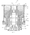
- Figure 1 is a sectional view of a vacuum pump in accordance with the present invention
- Figure 2 is a horizontal sectional view of a vacuum pump in accordance with the present invention, being at a position where a cooling water pipe is buried in a stator column
- Figure 3 is an enlarged sectional view of an end of a cooling water pipe of the vacuum pump in accordance with the present invention.
- a vacuum pump 100 in accordance with the present invention is a composite pump of a turbo-molecular pump and a thread groove pump.
- a stator column 102a containing an electrical equipment section consisting of a drive motor 103a and magnetic bearings 103b.
- a base 102b is formed integrally with the stator column 102a and extends in the horizontal direction.
- a rotor shaft 101a is arranged, the rotor shaft 101a projecting from an upper part of the stator column 102a.
- a rotor 101 is fastened.
- the rotor shaft 101a is held rotatably by the magnetic bearings 103b, and is rotated by the drive motor 103a. Therefore, since the rotor shaft 101a is held rotatably and rotated, the rotor 101 is rotated by the electrical equipment section consisting of the drive motor 103a and the magnetic bearings 103b.
- the rotor 101 has a cross-sectional shape such as to cover the outer periphery of the stator column 102a, and at the upper outer periphery of the rotor 101, rotating blades 106 are arranged in multiple stages. Also, stationary blades 107 are arranged in multiple stages so as to abut on the inner peripheral surface of the pump case 109. The rotating blades 106 and the stationary blades 107 are arranged alternately. Further, under the stationary blade 107 in the lowest stage, a thread stator 108 is arranged so as to abut on the inner peripheral surface of the pump case 109, and in the inner peripheral surface of the thread stator 108, a thread groove 108a is formed.
- Gas transfer means is formed by the inner peripheral surface of the above-described rotor 101, the rotating blades 106, the stationary blades 107, and the thread groove 108a, and also gas molecules flow in a clearance between the inner peripheral surface of the above-described rotor 101, the rotating blades 106, the stationary blades 107, and the thread groove 108a, forming a gas flow path.
- the stator column 102a is cast by a casting, and in the wall of the stator column 102a, namely, in a thick portion of wall forming the stator column 102a, a cooling water pipe 104 is buried by casting.
- the cooling water pipe 104 is formed, for example, of a stainless steel, and is cast. As shown in Figure 2, the cooling water pipe 104 is buried so as to make a round near the drive motor 103a, and both end sides thereof are extended from the stator column 102a to the base 102b side, and communicate with the outside of the vacuum pump 100 as a water supply port 104a and a water drain port 104b.
- the base 102b extends integrally from the lower surface of the stator column 102a, there is no need for burying the cooling water pipe 104 separately in the stator column 102a portion and in the base 102b portion and for aligning the openings of the cooling water pipes 104.
- the cooling water pipe 104 may make a plurality of rounds in the wall of the stator column 102a so as to be brought close to an electrical equipment section other than the drive motor 103a.
- the cooling water pipe 104 is buried in the wall of the stator column 102a, so that the cooling water pipe 104 can be provided just near the electrical equipment section arranged in the vicinity of the center of the vacuum pump 100. Therefore, only the electrical equipment section is cooled locally, and there is no need for propagating the cooling effect via other parts.
- the cooling water pipe 104 extended to the base 102b communicates with the outside of the vacuum pump 100 with one end being the water supply port 104a and the other end being the water drain port 104b.
- each of the water supply port 104a and the water drain port 104b is branched into a plurality of branches.
- each of the water supply port 104a and the water drain port 104b is branched into two branches, so that the cooling water pipe 104 communicates with the outside of the vacuum pump 100, by way of the branch of the water supply port 104a.
- one of the branches of the water supply port 104a is facing to the side surface of the base 102b and the other to the bottom surface of the base 102b, enabling communication with the outside of the vacuum pump 100 from either the side surface of the base 102b or the bottom surface of the base 102b.
- the water drain port 104b of the cooling water pipe 104 branched into two branches, one of the branches of the water drain port 104b facing to the side surface of the base 102b and the other to the bottom surface of the base 102b.
- both ends of the cooling water pipe 104 communicate with the outside of the vacuum pump 100 on the side opposite to an electrical outlet 110.
- both ends of the cooling water pipe 104 may communicate with the outside of the vacuum pump 100 at both sides of the electrical outlet 110.
- the branches of the water supply port 104a or the water drain port 104b may respectively communicate with the outside of the vacuum pump 100 in different directions to each other. Therefore, the user can use a branch convenient for using, and thereby the vacuum pump 100, in which the cooling water pipe 104 is buried in the stator column 102a, is available for practical use in any semiconductor manufacturing plant.
- Outer piping can be easily connected with the vacuum pump 100 by way of the port branches of the cooling water pipe 104 on the bottom surface, even if the water supply port 104a branch and the water drain port 104b branch on the side surface cannot be used depending on the installation state of semiconductor manufacturing plant, so that the vacuum pump 100 is available for practical use in any equipment state.
- the cooling water pipe 104 has water supply port 104a and the water drain port 104b, each of the ports being branched into two branches and communicating with outside by way of branches, one of the branches in the supply port 104a directed and facing to the side surface of the base 102b and the other to the bottom surface of the base 102b, similarly, one of the branches in the drain port 104b directed and facing to the side surface of the base 102b and the other to the bottom surface of the base 102b.
- a joint 105 is respectively fixed by welding.
- This joint 105 is buried in the base 102b so that the outside end of the joint 105 and the outer surface of the base 102b are flush with each other.
- the cooling water pipe 104 and the joint 105 are formed of the same metal. If the cooling water pipe 104 is formed of a stainless steel, the joint 105 is also formed of the stainless steel.
- the joint 105 is fixed at the ends of the cooling water pipe 104, and the joints 105 are buried so that the outside end of the joint 105 and the external surface of the vacuum pump 100 such as the base 102b are flush with each other. Therefore, the cooling water pipe 104 does not project to the outside of the vacuum pump 100, and at cooling water pipe setting, there is no fear of any warping or setting error of the cooling water pipe 104, or any damage on the stator column 102a.
- the joint 105 and the cooling water pipe 104 are formed of the same metal, there is no potential difference between the joint 105 and the cooling water pipe 104. Therefore, even if a refrigerant is allowed to flow, no current flows, and hence corrosion does not occur.
- the vacuum pump 100 in accordance with this embodiment is configured as described above, and cooling water or a refrigerant, such as a liquid or a gas, having a strong heat exchanging action is allowed to flow in the cooling water pipe 104 to cool the nearby electrical equipment section with other parts scarcely lying between the cooling water pipe 104 and the electrical equipment section.
- each of the water supply port 104a and the water drain port 104b branches into two sections and communicates with the outside of the vacuum pump 100 from the side surface and bottom surface of the base 102b, so that one port of the two sections is connected to an outer pipe via the joint 105 by the user's selection.
- the vacuum pump 100 is fixed in a hollow state in the process chamber of semiconductor manufacturing apparatus, not shown, by a flange provided in an upper part of the pump case 109.
- the outer pipe for supplying refrigerant is connected to the port of the branched cooling water pipe 104, which communicates with the outside of the vacuum pump 100 from the side surface of the base 102b.
- the arrangement position and arrangement direction of the stator column 102a is regulated automatically.
- the arrangement position and arrangement direction of the stator column 102a is regulated.
- the arrangement positions and arrangement directions of the water supply port 104a and the water drain port 104b of the cooling water pipe 104 are also regulated.
- the port of the branched cooling water pipe 104 which communicates with the outside of the vacuum pump 100 from the side surface of the base 102b is hidden behind the equipment, or lies on the side opposite to the arrangement position of the outer pipe, so that, in some cases, the outer pipe cannot be connected to the port. If an attempt is made to forcibly connect the outer pipe, the cooling water pipe 104 is damaged by the tensile force etc. of the outer pipe, or the position of the stator column 102a is shifted, and in the worst case, a failure of the vacuum pump 100 is caused.
- the outer pipe is connected to the port of the branched cooling water pipe 104, which communicates with the outside of the vacuum pump 100 from the bottom surface of the base 102b.
- the outer pipe is inserted and fixed in the joint 105, by which the connection is completed.
- the joint 105 is buried so as to be flush with the outer surface of the base 102b, the tensile force of the outer pipe, a force applied by the user, and the like are not applied to the end of the cooling water pipe 104, so that there is no fear that the cooling water pipe 104 gets twisted.
- the other port that has not been connected is covered with a lid, by which the installation of the vacuum pump 100 is completed.
- the outer pipe can be connected to the vacuum pump 100 by appropriately selecting the side surface or the bottom surface according to the installation state of semiconductor manufacturing apparatus.
- the rotating blade 106 in the uppermost stage which is rotating at a high speed, gives a downward momentum to the introduced gas molecules.
- the gas molecules having this downward momentum are sent to the rotating blade 106 side in the next stage by the stationary blade 107.
- the above operation in which the momentum is given to the gas molecules and the gas molecules are sent is repeated in multiple stages, by which the gas molecules are transferred in succession to the thread groove 108a side and are discharged. Further, the gas molecules reaching the thread groove 108a side by means of the molecule exhaust operation are compressed and transferred to the exhaust side by the interaction between the rotation of the rotor 101 and the thread groove 108a, and are discharged.
- the electrical equipment section such as the drive motor 103a and the magnetic bearings 103b, rotates the rotor 101 at several ten thousand r.p.m until a vacuum is generated in the process chamber, and soon begins to generate heat.
- a refrigerant is allowed to flow in the cooling water pipe 104 through the outer pipe.
- the cooling water pipe 104 buried in the stator column 102a begins to achieve the cooling effect.
- the refrigerant flowing in the cooling water pipe 104 acts so as to mainly cool the nearby electrical equipment section and absorb heat.
- the cooling water pipe 104 since the cooling water pipe 104 is buried in the wall of the stator column 102a, the cooling effect of the cooling water pipe 104 propagates in the stator column 102a and acts so as to cool the nearby electrical equipment section. Therefore, the cooling water pipe 104 has only to have cooling capacity enough to cool the nearby electrical equipment section, and the cooling effect is transmitted not propagate to the base 102b and the thread stator 108 through the stator column 102a. As a result, the electrical equipment section maintains a stable temperature without temperature rise caused by heat generation of the electrical equipment section itself, the cooling effect is less prone to propagate to other members, and gas molecules are less prone to be deposited by the cooling effect of the cooling water pipe 104.
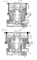
- Figures 4 (a) and 4 (b) are sectional views of vacuum pumps 200 and 300 in accordance with a second invention, showing that even in the vacuum pumps having different performance, their components are made common.
- Figure 5 is a horizontal sectional view of a vacuum pump 200 or 300 in accordance with the present invention, being at a position where a cooling water pipe 204 is buried in a stator column 202a.
- Figure 6 is a sectional view showing a state in which a (second) cooling water pipe 204A and a heater 411 are installed to a thread pump stator of the vacuum pump in accordance with the second invention of the present invention.
- the vacuum pumps 200 and 300 in accordance with this embodiment, shown in Figures 4 (a) and 4 (b), are composite pumps in which a turbo-molecular pump and a thread groove (208a or 308a) pump are compounded.
- an external casing is formed by a pump case 209 or 309, a thread pump stator 208 or 308 supporting the pump case 209, 309, and a base 202b supporting the thread pump stator 208, 308.
- the thread pump stator 208, 308 is erected at a fixed position in an upper surface edge portion of the base 202b, and is supported by the base 202b.
- the pump case 209, 309 is provided with a fastening portion 209a, 309a at the lower edge thereof, and on the other hand, the thread pump stator 208, 308 is extendedly provided so that a flange 208b, 308b projects from the upper edge thereof, and the flange 208b, 308b is extended to the fastening portion 209a, 309a.
- the fastening portion of the pump case is not present above the thread pump stator because the thread pump stator is erected at the fixed position of the base.
- this vacuum pump 200, 300 since the flange 208b, 308b is extended to the fastening portion 209a, 309a, even if the thread pump stator 208, 308 is erected at the fixed position of the base 202b, the flange 208b, 308b and the fastening portion 209a, 309a can be fastened to each other, so that the pump case 209, 309 is supported by the thread pump stator 208, 308.
- a substantially cylindrical stator column 202a is formed integrally, and in the stator column 202a, a bearing mechanism and a drive motor are contained. Also, in the stator column 202a, a rotor shaft 201a, 301a is arranged. The rotor shaft 201a, 301a projects from an upper part of the stator column 202a.
- a rotor 201, 301 is fastened to an end portion of the rotor shaft 201a, 301a.
- This rotor 201, 301 has a shape such as to cover the stator column 202a.
- rotating blades 206, 306 are arranged in multiple stages.
- stationary blades 207, 307 are arranged in multiple stages so as to abut on the inner peripheral surface of the pump case 209, 309. The rotating blades 206, 306 and the stationary blades 207, 307 are arranged alternately.
- a thread groove 208a, 308a is formed.
- the thread groove may be formed at a position where the thread pump stator 208, 308, not the inner peripheral surface of the thread pump stator 208, 308, faces to the rotor 201, 301.
- the stator column 202a is a casting cast integrally with the base 202b, and in the wall surface of the stator column 202a, namely, in a thick portion of wall forming the stator column 202a, a cooling water pipe 204 is buried by casting.
- the cooling water pipe 204 is buried so as to make a round around the stator column 202a, and both ends thereof are extended to the base 202b, and communicate with the outside of the vacuum pump 200, 300 from the outer surface of the base 202b with one end being a water supply port 204a and the other end being a water drain port 204b.
- gas transfer means is formed by the outer peripheral surface of the rotor 201, 301, the rotating blades 206, 306, the stationary blades 207, 307, and the thread groove 208a, 308a, and also gas molecules flow in a clearance between the outer peripheral surface of the rotor 201, 301, the rotating blades 206, 306, the stationary blades 207, 307, and the thread groove 208a, 308a, forming a gas flow path.
- the gas molecules having this downward momentum are sent to the rotating blade 206, 306 side in the next stage by the stationary blade 207, 307.
- the above operation in which the momentum is given to the gas molecules and the gas molecules are sent is repeated in multiple stages, by which the gas molecules are transferred in succession to the thread groove 208a, 308a side and are discharged. Further, the gas molecules reaching the thread groove 208a, 308a side by means of the molecule exhaust operation are compressed and transferred to the exhaust side by the interaction between the rotation of the rotor 201, 301 and the thread groove 208a, 308a, and are discharged.
- the vacuum pumps 200 and 300 of this embodiment as shown in Figures 4(a) and 4(b) have the same configuration and the same operation and function, but have a different shape as shown in Figures 4(a) and 4(b).
- the lengths of the rotating blades of the vacuum pump 300 shown in Figure 4 (b) are longer than those of the vacuum pump 200 shown in Figure 4 (a) .
- the number of stages of the rotating blades is nine in the vacuum pump 200 shown in Figure 4(a), whereas the number of stages of the rotating blades is small, being seven, in the vacuum pump 300 shown in Figure 4 (b) .
- the bore of the pump case of the vacuum pump 300 shown in Figure 4(b) is larger than that of the vacuum pump 200 shown in Figure 4 (a) .
- This difference in bore between the pump cases 209 and 309 is caused by a difference in length between the rotating blades 206 and 306.
- the shape of the rotor 201, 301 differs between the vacuum pump 200 shown in Figure 4(a) and the vacuum pump 300 shown in Figure 4(b). This difference in shape between the rotors 201 and 301 is caused by a difference in length and number of stages between the rotating blades 206 and 306.
- the base 202b and the stator column 202a formed integrally with the base 202b have the same shape and the same size.
- the base 202b and the stator column 202a formed integrally with the base 202b are common in the vacuum pump 200 and 300 shown in Figures 4(a) and 4(b).
- the base 202b and the stator column 202a formed integrally with the base 202b may be common in the vacuum pumps 200 and 300 shown in Figures 4(a) and 4(b) although the pump cases 209, 309, the lengths and the number of stages of the rotating blades 206, 306, and the shape of the rotors 201, 301 differ in the vacuum pumps 200 and 300 shown in Figures 4(a) and 4(b).
- the cooling water pipe 204 is buried in the wall of the stator column 202a. Cooling water or a refrigerant, such as a liquid or a gas, having a strong heat exchanging action is allowed to flow in the cooling water pipe 204 through the water supply port 204a, and is drained through the water drain port 204b.
- a refrigerant such as a liquid or a gas
- the sufficiently cooled stator column 202a can sufficiently absorb heat of vacuum pump components separated to some extent. Specifically, the sufficiently cooled stator column 202a can sufficiently absorb heat of the rotor 201, 301 and the rotating blades 206, 306 even if the rotor 201, 301 is separated to some extent from the stator column 202a, so that rise in temperatures of the rotor 201, 301 and the rotating blades 206, 306 is depressed.
- stator column 202a In case that the rotor 201, 301 is separated to some extent from the stator column 202a, the outer peripheral surface shape of the stator column 202a is not regulated so as to match the inner peripheral surface shape of the rotor 201, 301. Therefore, even in the vacuum pumps 200, 300 in which the shape of the rotors 201, 301 are different to each other, shown in Figures 4 (a) and 4 (b), the stator column 202a can be designed freely, and the stator column 202a can be made common in size and shape.
- stator column 202a The cooling water pipe 204 being buried in the stator column 202a in this manner, for effective cooling, the outer peripheral surface shape of the stator column 202a does not need any regulation by the inner peripheral surface shapes of the rotors 201, 301. Therefore, a common stator column 202a may be used even in the vacuum pumps 200 and 300 which have the same configuration and the same operation and function but have a different shape.
- the vacuum pump 200, 300 of this embodiment is provided with the thread pump stator 208, 308 which supports the pump case 209, 309 and is supported by the base 202b.
- the thread pump stator 208, 308 which supports the pump case 209, 309 and is supported by the base 202b.
- the external casing consists. That is to say, the pump case 209, 309 and the base 202a are fastened to each other via the thread pump stator 208, 308.
- the base 202b is configured so that the thread pump stator 208, 308 is erected at the fixed position on the upper surface of the base 202b and is supported.
- the thread pump stator 208, 308 erected at the fixed position of the base 202b supports the pump case 209, 309 by fastening the fastening portion 209a, 309a of the pump case 209, 309 to the flange 208b, 308b of the thread pump stator 208, 308.
- the bores of the pump cases are different from each other .
- the thread pump stator 208, 308 is formed so that the flange 208b, 308b is extended a predetermined distance to the fastening portion 209a, 309a of the pump case 209, 309.
- the fastening portion 209a, 309a of the pump case 209, 309 may be extended a predetermined distance to the flange 208b, 308b of the thread pump stator 208, 308.
- the thread pump stator 208, 308 By forming the thread pump stator 208, 308 so that the flange 208b, 308b is extended to the fastening portion 209a, 309a of the pump case 209, 309, the pump case 209, 309 can be supported by the thread pump stator 208, 308 even in the case where the thread pump stator 208, 308 is erected at the fixed position on the upper surface of the base 202b.
- the base 202b supports the thread pump stator 208, 308 erected at the fixed position without supporting the pump case 209, 309, and further the flange 208b, 308b of the thread pump stator 208, 308 is adjustably formed by being extended a predetermined distance according to the pump case 209, 309, by which there is no need for regulating the size of the base 202b by being regulated by the bore of the pump case 209, 309.
- the base 202b can be designed freely, and the base 202b can be made common in size and shape.
- the size of the base 202b is not regulated by the bore of the pump case 209, 309. Therefore, a common base 202b can be used even in the vacuum pumps which have the same configuration and the same operation and function but have a different shape.
- the base 202b and the stator column 202a formed integrally with the base 202b are made common.
- the base 202b and the stator column 202a formed integrally with the base 202b that have been made common can be manufactured and controlled easily as one part, and the cost required for manufacture and inventory management can be saved. In addition, a problem of inherent trouble is reduced, and even if a trouble occurs, the time required for identifying the trouble can be saved.
- the base 202b and the stator column 202a are formed integrally. However, even if the base 202b and the stator column 202a are formed separately, these elements can be made common.
- the integration of the stator column 202a with the base 202b contributes to the reduction in cost. In addition, the integration eliminates the need for burying the cooling water pipe 204 separately in the stator column 202a portion and in the base 202b portion and for aligning the openings of the cooling water pipes 204.
- the vacuum pump 300 shown in Figure 4 (b) can use the base 202b and the stator column 202a formed integrally with the base 202b that are shown in Figure 4 (a) as a component although the vacuum pump 300 has long rotating blades 306, a small number of stages of the rotating blades 306, a large bore of the pump case 309, and the rotor 301 having a different shape as compared with the vacuum pump 200 shown in Figure 4 (a) .
- the base 202b and the stator column 202a formed integrally with the base 202b can be made common.
- the vacuum pump 400 is further provided with a second cooling water pipe 204A and the heater 411, which are installed on the outer surface of a thread pump stator 408.
- the outer surface is exposed to the outside of the vacuum pump 400.
- the thread pump stator 408 functions as a part of the external casing.
- the second cooling water pipe 204A is another from the cooling water pipe 204 buried in the stator column 202a.
- the thread pump stator 408 faces to a rotor 401 like the stator column 202a because a thread groove 408a formed in the thread pump stator 408 and a gas flow path below the rotor 401 are provided. Specifically, the lower part of the rotor 401 is interposed between the stator column 202a and the thread pump stator 408.
- the cooling water pipe 204A installed on the outer surface of the thread pump stator 408 achieves the cooling effect to cool the thread pump stator 408.
- the cooled thread pump stator 408 absorbs heat of the facing rotor 401, and the cooled stator column 202a absorbs heat, by which the rise in temperatures of the rotor 401 and rotating blades 406 is inhibited.
- the stator column 202a and the rotor 401 need not be further brought close to each other, so that the distance between the stator column 202a and the rotor 401 can further be increased. If the distance between the stator column 202a and the rotor 401 can further be increased, the stator column 202a can be designed freely regardless of the inner peripheral shape of the rotor 401, and hence the stator column 202a can further be made common.
- some semiconductor manufacturing process is a process in which gas molecules that have a high saturated vapor pressure and are less prone to change into a liquid or a gas flow in the vacuum pump 400.
- the lowering of the temperature in the vacuum pump 400 rather inhibits the rise in temperatures of the rotor 401 and the rotating blades 406.
- the cooling water pipe 204A is installed on the outer surface of the thread pump stator 408, since the thread pump stator 408 is directly adjacent to the interior of the vacuum pump 400, the cooling effect in the vacuum pump 400 is enhanced, and hence the rise in temperatures of the rotor 401 and the rotating blades 406 can be inhibited surely.
- the heat produced by the heater 411 installed on the outer surface of the thread pump stator 408 warms the thread pump stator 408. Since the thread pump stator 408 is contiguous to the gas flow path, the warmed thread pump stator 408 radiates heat to warm the gas flow path.
Landscapes
- Engineering & Computer Science (AREA)
- Mechanical Engineering (AREA)
- General Engineering & Computer Science (AREA)
- Physics & Mathematics (AREA)
- Thermal Sciences (AREA)
- Non-Positive Displacement Air Blowers (AREA)
- Applications Or Details Of Rotary Compressors (AREA)
Abstract
Description
- The present invention relates to a vacuum pump used for semiconductor manufacturing apparatus and, more particularly, to a vacuum pump in which a cooling water pipe is buried in the wall of a stator column.
- In a process for performing work in a process chamber of a high vacuum such as a process of dry etching etc. in a semiconductor manufacturing process, a vacuum pump is used as a means for exhausting the gas in the process chamber to generate a high vacuum in the process chamber.
- As the vacuum pump, various types of pumps such as a turbo-molecular pump and a thread groove pump are available. For example, as a conventional vacuum pump, a composite vacuum pump in which a turbo-molecular pump and a thread groove pump are compounded is used.
- In the vacuum pump, rotating blades and stationary blades provided in multiple stages on the upper inner peripheral surface of a pump case function as a turbo-molecular pump by means of the rotation of a rotor. By the function of the turbo-molecular pump, a downward momentum is given to the introduced gas, and the gas is transferred to the exhaust side. Also, in the vacuum pump, a thread groove and the rotor function as a thread groove pump by means of the rotation of the rotor. By the function of the thread groove pump, gas is compressed from an intermediate flow to a viscous flow and transferred to the gas discharge port side (for example, refer to Patent Document 1).
- For example, as shown in Figure 7, in a
conventional vacuum pump 500, astator column 502a is erected on the upper surface of abase 502b. In thestator column 502a, an electrical equipment section consisting of adrive motor 503a andmagnetic bearings 503b is disposed, and also arotor 501 projecting from the interior of thestator column 502a is provided. Therotor 501 is rotatably held by themagnetic bearings 503b, and is rotated by thedrive motor 503a. - At the upper outer periphery of the
rotor 501, rotatingblades 506 are provided in multiple stages. These rotatingblades 506 andstationary blades 507 provided in multiple stages on the upper inner peripheral surface of thevacuum pump 500 function as a turbo-molecular pump by means of the rotation of therotor 501. By this turbo-molecular pump, a downward momentum is given to the introduced gas, and the gas is transferred to the exhaust side. - Further, on the lower inner peripheral surface of the
vacuum pump 500, athread stator 508 is provided, and at a position where thethread stator 508 faces to the lower outer periphery of therotor 501, athread groove 508a is formed. Thethread groove 508a and therotor 501 function as a thread groove pump by means of the rotation of therotor 501. By this thread groove pump, gas is compressed from an intermediate flow to a viscous flow and transferred to the gas discharge port side. - In the above-described
vacuum pump 500, since the electrical equipment section consisting of thedrive motor 503a andmagnetic bearings 503b is allowed to function by electric power, heat is produced in the electrical equipment section. Due to the produced heat, thevacuum pump 500 has a fear that thedrive motor 503a is burned and themagnetic bearings 503b are destroyed. - To solve this problem, conventionally, the configuration has been such that a
cooling water pipe 504 is installed on the outside of thevacuum pump 500, on the lower surface of thestator column 502a, and on the outside of thebase 502b, and cooling water or a refrigerant, such as a liquid or a gas, having a strong heat exchanging action is allowed to flow to cool the electrical equipment section (for example, refer to Patent Document 2). - However, in the
conventional vacuum pump 500, since thecooling water pipe 504 is installed on the outside of thevacuum pump 500 and on the outside of thestator column 502a, the electrical equipment section and thecooling water pipe 504 are greatly separated from each other. In particular, thedrive motor 503a having the greatest heat generating effect among the electrical equipment section is arranged approximately in the center of thevacuum pump 500, so that it is greatly separated from thecooling water pipe 504. If the electrical equipment section and thecooling water pipe 504 are separated greatly from each other, a loss of cooling effect occurs during the time when the cooling effect of thecooling water pipe 504 reaches the electrical equipment section, so that the electrical equipment section cannot be cooled effectively. - If the cooling force of the
cooling water pipe 504 is increased, the cooling effect can be allowed to reach the electrical equipment section even if the loss of cooling effect occurs. In this case, however, the cooling effect also reaches a gas flow path, for example, in thethread stator 508 other than the electrical equipment section, so that there is a danger that the liquefaction or solidification of gas is promoted, and hence gas molecules are deposited in thevacuum pump 500. When the deposition of gas molecules is considered, there is a limit to the increase in cooling force of thecooling water pipe 504. Consequently, in the case where thecooling water pipe 504 is installed on the outside of thevacuum pump 500, on the lower surface of thestator column 502a, and on the outside of thebase 502b, it is difficult to cool the electrical equipment section with high efficiency. - Also, as a function of this cooling water pipe, the rise in temperatures of the rotating blades and the rotor is depressed.
- In the vacuum pump, the rotor and the rotating blades are rotated at a high speed to exhaust the gas in the process chamber, and the rotating blades and the rotor produce frictional heat and compression heat with respect to the gas flow, so that the rotating blades and the rotor have an abnormally high temperature which may exceed the heat-resisting temperature. Therefore, in order to depress the rise in temperatures of the rotating blades and the rotor, the stator column is cooled, and hence the heat of the rotor and the rotating blades is absorbed by the cooled stator column.
- Conventionally, to cool the stator column, too, there has been adopted the above-described method, namely, the method in which the
cooling water pipe 504 is installed on the outer surface of thebase 502b, and by installing thiscooling water pipe 504, the cooling effect of thecooling water pipe 504 is allowed to reach the upper part of thestator column 502a via thebase 502b, or the method in which the cooling water pipe is installed on the bottom surface of thestator column 502a, and the cooling effect of the cooling water pipe is allowed to reach from the bottom surface to the top surface. - However, with this method, the cooling effect of the
cooling water pipe 504 decreases in the upper part of thestator column 502a, especially near the lower stages of the rotatingblades 506. - On the other hand, the cooling effect can be allowed to reach the
stator column 502a by increasing the cooling capacity of thecooling water pipe 504. However, if the cooling capacity of thecooling water pipe 504 is increased, the cooling effect also propagates, for example, to thethread stator 508, and hence gas molecules deposit in thethread groove 508a depending on the semiconductor manufacturing process. - Consequently, there is a limit to the increase in the cooling capacity of the
cooling water pipe 504. In order to absorb the heat on therotor 501 side by means of the cooledstator column 502a, it is preferable that thestator column 502a be placed as close as possible to the inner peripheral surface of therotor 501. - For this reason, conventionally, the shape of the outer peripheral surface of the
stator column 502a has been almost the same as the shape of the inner peripheral surface of therotor 501. - Therefore, if the shape of the
rotor 501 is different, the shape of thestator column 502a is also different, and hence the shape of therotor 502a is different from vacuum pump to vacuum pump. Similarly, the bore of a pump case 509, the size of thebase 502b supporting the pump case 509, the shape of therotor 501, the shape of thestator column 502a, the length and width of the rotatingblade 506, and the number of stages in which therotating blades 506 are disposed are also different from vacuum pump to vacuum pump. The same is true for a vacuum pump of the same mechanism. - The individual reasons for the above will be explained below with reference to Figures 8(a) and 8(b) showing vacuum pumps of the same mechanism.
-
Vacuum pumps vacuum pump pump case base pump case base pump case base vacuum pump - In the
vacuum pump rotor stator column base rotor stator column stator column rotor stator column rotor rotor stator column stator column - At the upper outer periphery of the
rotor blades rotating blades rotating blade - On the lower inner peripheral surface of the
pump case thread pump stator thread groove thread pump stator rotor - On the outer surface of the
base cooling water pipe stator column cooling water pipe - First, the reason why the
rotating blades blades vacuum pump rotating blades rotating blades - For example, in the
vacuum pump 700 shown in Figure 8 (b), therotating blades 706 are longer as a whole than the rotatingblades 606 of thevacuum pump 600 shown in Figure 8(a). In thevacuum pump 600 shown in Figure 8 (a), the rotatingblades 606 are arranged in nine stages, whereas in thevacuum pump 700 shown in Figure 8 (b), therotating blades 706 are arranged in seven stages. - The reason why the shape of the
rotor rotating blades rotor rotor rotor - Therefore, as shown in Figures 8(a) and 8(b), even in the
vacuum pump rotating blades rotating blades rotor - For example, if the
rotating blade rotor rotating blade rotor rotating blade rotor rotating blade rotor - The reason why the bore of the
pump case rotating blades rotating blade base pump case rotating blades - Therefore, as shown in Figures 8(a) and 8(b), even in the
vacuum pump rotating blades rotating blades base - In the above-described
vacuum pump pump case base pump case vacuum pump rotor rotor stator column stator column rotor stator column vacuum pump rotating blades - Thus, each component constituting the
vacuum pump vacuum pump -
- Patent Document 1: Japanese Patent Laid-Open No. 2003-184785 (Figure 5)
- Patent Document 2: Japanese Patent No. 3084622 (page 2, Figure 6)
- As described above, in the conventional vacuum pump, the cooling water pipe is arranged on the outside of the vacuum pump, on the lower surface of the stator column, and on the outside of the base. Therefore, the conventional vacuum pump has a problem in that the cooling effect is difficult to reach the electrical equipment section that must be cooled, especially the drive motor.
- If the cooling effect does not reach the electrical equipment section efficiently, the electrical equipment section has a danger of burning and destruction. Also, if the cooling effect reaches the electrical equipment section from the outside of the vacuum pump, the lower surface of the stator column, or the outside of the base, the gas flow path is also cooled, so that gas molecules are deposited in the vacuum pump. Therefore, there is a danger that the deposits come into contact with the rotor, and hence the vacuum pump is damaged.
- Accordingly, one object of the present invention is to provide a vacuum pump in which the electrical equipment section for rotating the rotor is cooled efficiently, in proper temperature.
- Also, in the conventional vacuum pump, since the length and width of the rotating blades and further the number of stages are different from vacuum pump to vacuum pump, and also the rotor whose shape is substantially regulated because the length and width of the rotating blades and further the number of stages are different is cooled, each component has been manufactured individually into a different shape according to the vacuum pump.
- If each component is manufactured individually into a different shape according to the vacuum pump, a very high cost is required for manufacture and inventory management. In addition, there is a fear that the vacuum pump after being assembled gets into trouble inherent in that vacuum pump, so that it takes much time to identify the trouble.
- Accordingly, another object of the present invention is to provide plural types of vacuum pumps capable of using common vacuum pump components even for a vacuum pump having a different size and shape though having the same structure, and to make the vacuum pump components common.
- The vacuum pump in accordance with a first invention for solving one of the problems with the above-described conventional art is a vacuum pump which generates vacuum by rotating a rotor to suck and discharge a gas, characterized by including an electrical equipment section for rotating the rotor; a stator column containing the electrical equipment section; a base formed integrally with the stator column; and a cooling water pipe buried in the wall of the stator column, and provided with a branched water inlet port and a branched water outlet port.
- In this invention, the term "electrical equipment section" means a drive motor for rotating at least the rotor. The electrical equipment section generates power when the vacuum pump is mechanically operated. Also, in the case where the bearing mechanism is a magnetic bearing, the magnetic bearing is also included in the electrical equipment section because an electromagnet is arranged, and a magnetic field is produced by electric power to hold the rotor.
- The phrase "the wall of the stator column" means a thick portion of the wall having a predetermined thickness, which forms the stator column.
- The phrase "branched" means that the inlet port and outlet port of the cooling water pipe are respectively divided into a plurality of cooling water pipes, and all of the plurality of cooling water pipes have a function of allowing a refrigerant water to flow.
- By the above-described configuration, the cooling water pipe is provided just near the electrical equipment arranged near the center of the vacuum pump. Therefore, only the electrical equipment is cooled locally and hence the cooling effect becomes excellent. Also, since cooling is not transmitted via other members, a danger of depositing gas molecules in the vacuum pump becomes reduced.
- Further, in the present invention, the water supply port and the water drain port of the cooling water pipe are allowed to communicate with outside in different directions. If the cooling water pipe is buried in the stator column, the locations of the water supply port and the water drain port of the cooling water pipe are regulated by the regulation of the arrangement position and the arrangement direction of the stator column. In the present invention, however, the user can select and use one branch convenient for using, from plural branches of cooling water pipe extended in different directions. For the vacuum pump configured as described above, the user need not rack his/her brains over the layout of the outer pipes for the vacuum pump, and the vacuum pump is easy to use. In addition, the vacuum pump in which the cooling water pipe is buried in the stator column is available for practical use in any equipment state.
- Also, the vacuum pump in accordance with the present invention may be configured so that each of the water inlet port and the water outlet port are branched into two branches and disposed in the base, one branch of the water inlet port and one branch of the water outlet port being communicated with the outside of the vacuum pump at the side surface of the base, and the others with the outside of the vacuum pump at the bottom surface of the base.
- Herein, the phrase "one branch" means one of two branched inlet port or outlet port of cooling water pipes.
- By the above-described configuration, the water supply port and the water drain port of the cooling water pipe each can be allowed to communicate with the side and the bottom of the vacuum pump. Therefore, depending on the installation state of semiconductor manufacturing apparatus, even if the water supply port and the water drain port in the side surface cannot be used, the outer pipe can be connected to the bottom surface. Therefore, the user need not rack his/her brains over the layout of the outer pipes, and the vacuum pump is easy to use. In addition, the vacuum pump in which the cooling water pipe is buried in the stator column is available for practical use in any equipment state.
- Also, the vacuum pump in accordance with the present invention is a vacuum pump which generates vacuum by rotating the rotor to suck and discharge a gas, characterized by including an electrical equipment section for rotating the rotor; a stator column containing the electrical equipment section; a base formed integrally with the stator column; a cooling water pipe buried in the wall of the stator column; and a plurality of joints which are fixed to each ends of the cooling water pipe and buried in the vacuum pump flush with the external surface of the pump.
- By the above-described configuration, the cooling water pipe can be provided just near the electrical equipment section arranged near the center of the vacuum pump. Therefore, only the electrical equipment section is cooled locally and hence the cooling effect is excellent. Also, since cooling is not transmitted via other members, a danger of depositing gas molecules in the vacuum pump can be reduced.
- Further, since the cooling water pipe does not project to the outside of the vacuum pump, at the time of laying the piping, there is no fear that the cooling water pipe is distorted, the position of the stator column is shifted, or the stator column is damaged. Therefore, the cooling capacity of the cooling water pipe can be maintained, and also the life of the vacuum pump is increased.
- Also, in the vacuum pump in accordance with the present invention, the joint and the cooling water pipe may be formed of the same metal.
- In the above-described configuration, there is no potential difference between the joint and the cooling water pipe. Therefore, even if a refrigerant is allowed to flow, no current flows, and hence corrosion does not occur, so that the cooling capacity of the cooling water pipe can be maintained, and also the life of the vacuum pump is increased.
- The vacuum pump in accordance with a second invention for solving another one of the problems with the above-described conventional art is a vacuum pump which generates vacuum by sucking and discharging a gas,
characterized by including a pump case for the vacuum pump; a thread pump stator for supporting the pump case; a base for supporting the thread pump stator; a stator column formed integrally with the base; a rotor arranged so as to cover the stator column; rotating blades provided in multiple stages at the outer periphery of the rotor; and a cooling water pipe buried in the wall of the stator column. - Herein, the term "thread pump stator" means a stator interacting with the rotor. The thread pump stator functions as a thread groove pump by means of the interaction with the rotor. In this case, it is a matter of course that a thread groove is formed. The thread groove may be formed on the thread pump stator side or on the rotor side.
- Herein, the phrase "the wall of the stator column" means a thick portion of the wall having a predetermined thickness, which forms the stator column.
- Herein, the phrase "arranged so as to cover" means that the stator column lies on the inner peripheral surface side of the rotor. The distance between the inner peripheral surface of the rotor and the outer peripheral surface of the stator column is not a concern. Therefore, the stator column has only to face to the inner peripheral surface side of the rotor regardless of the size of the stator column.
- Also, the pump case may have a fastening portion which is fastened to the thread pump stator to support the pump case, and the thread pump stator may have a flange which extends from the thread pump stator and fastens the pump case to support the pump case.
- Also, the external casing of the vacuum pump may be formed by the pump case, the thread pump stator, and the base.
- Also, in the vacuum pump in accordance with the present invention, the inner peripheral surface shape of the rotor and the outer peripheral surface shape of the stator column may be different from each other.
- By the above-described configuration, even in the vacuum pumps of plural types each having a different size and shape due to the difference in required performance though having the same structure, the base and the stator column that have been made common can be made a vacuum pump component regardless of the shape of rotor and the bore of pump case, so that the cost required for manufacture and inventory management can be saved. In addition, a problem of inherent trouble is reduced, and even if a trouble occurs, the time required for identifying the trouble can be saved.
- Also, the vacuum pump in accordance with the present invention may further include a cooling water pipe arranged on the outer surface of the thread pump stator.
- By the above-described configuration, the stator column can further be made common regardless of the difference in rotor shape. Therefore, the cost required for manufacture and inventory management can be saved, and also a problem of inherent trouble is reduced and even if a trouble occurs, the time required for identifying the trouble can be saved. In addition, the rise in temperatures of the rotor and the rotating blades can be inhibited surely.
- Also, the vacuum pump in accordance with the present invention may further include a heater arranged on the outer surface of the thread pump stator.
- By the above-described configuration, the gas flow path having the function of a thread groove pump can be warmed, so that the production of gas deposits is prevented, and hence the reliability of the vacuum pump can be improved.
- As described above, the vacuum pump of the first invention is provided with a electrical equipment section for rotating the rotor , a cooling water pipe buried in the wall of a stator column formed integrally with a base, and a water supply port and a water drain port of the cooling water pipe respectively branched into plural branches. Therefore, the cooling water pipe is disposed just near the electrical equipment section near the center of the vacuum pump, so that only the electrical equipment section is cooled locally and hence the cooling effect is excellent. Also, a danger of depositing gas molecules in the vacuum pump is reduced, and further the water supply port and the water drain port of the cooling water pipe are allowed to communicate with outside in their required different directions. Therefore, the user can select and use one branch convenient for using, from plural branches of cooling water pipe extended in different directions, and the user need not rack his/her brains over the layout of the outer pipes for the vacuum pump, and the vacuum pump is easy to use. In addition, the vacuum pump in which the cooling water pipe is buried in the stator column is available for practical use in any the equipment state.
- Also, in the vacuum pump in accordance with the present invention, the water supply port and the water drain port of the cooling water pipe each are branched into two branches and extendedly provided in the base; and one of the branched water supply port communicates with the outside of the vacuum pump from the side surface of the base, and the other thereof communicates with the outside of the vacuum pump from the bottom surface of the base, and the water drain port is configured similarly. Therefore, even if the water supply port and the water drain port on the side surface cannot be used depending on the installation state of semiconductor manufacturing apparatus, outer pipes can be connected to the bottom surface, so that the user need not rack his/her brains over the layout of the outer pipes, and the vacuum pump is easy to use. In addition, the vacuum pump in which the cooling water pipe is buried in the stator column is available for practical use in any equipment state.
- In the vacuum pump in accordance with the present invention, the joints are respectively fixed at ends of cooling water pipe, and buriedly provided so that the outer end of the joint is flush with the external surface of the vacuum pump. Therefore, at the time of laying the piping, there is no fear that the cooling water pipe is distorted, the position of the stator column is shifted, or the stator column is damaged, so that the cooling capacity of the cooling water pipe can be maintained, and also the life of the vacuum pump is increased.
- Also, in the vacuum pump in accordance with the present invention, the joint and the cooling water pipe are formed of the same metal. Therefore, there is no potential difference between the joint and the cooling water pipe, so that even if a refrigerant is allowed to flow, no current flows, and hence corrosion does not occur. Thereby, the cooling capacity of the cooling water pipe can be maintained, and also the life of the vacuum pump is increased.
- In the vacuum pump of the second invention, the pump case is supported by the flange of the thread pump stator, and the cooling water pipe is buried in the wall of the stator column. Therefore, even in the vacuum pumps of plural types each having a different size and shape due to the difference in required performance though having the same structure, the base and the stator column that have been made common can be made a vacuum pump component regardless of the shape of rotor and the bore of pump case, so that the cost required for manufacture and inventory management can be saved. In addition, a problem of inherent trouble is reduced, and even if a trouble occurs, the time required for identifying the trouble can be saved.
- Also, in the vacuum pump in accordance with the present invention, the cooling water pipe is installed on the outer surface of the thread pump stator supporting the pump case. Therefore, the stator column can further be made common regardless of the difference in rotor shape, so that the cost required for manufacture and inventory management can be saved, and also a problem of inherent trouble is reduced and even if a trouble occurs, the time required for identifying the trouble can be saved. In addition, the rise in temperatures of the rotor and the rotating blades is surely inhibited.
- Also, in the vacuum pump in accordance with the present invention, the heater is installed on the outer surface of the thread pump stator supporting the pump case. Therefore, the thread pump stator having the thread groove, which is a gas flow path in which gas deposits are liable to accumulate, can be warmed directly. Therefore, the production of gas deposits is prevented, and hence the reliability of the vacuum pump can be improved.
- A preferred embodiment of a vacuum pump in accordance with a first invention will now be described in detail with reference to Figures 1 to 3.
- Figure 1 is a sectional view of a vacuum pump in accordance with the present invention, Figure 2 is a horizontal sectional view of a vacuum pump in accordance with the present invention, being at a position where a cooling water pipe is buried in a stator column, and Figure 3 is an enlarged sectional view of an end of a cooling water pipe of the vacuum pump in accordance with the present invention.
- A
vacuum pump 100 in accordance with the present invention, shown in Figure 1, is a composite pump of a turbo-molecular pump and a thread groove pump. - In a
pump case 109 of thevacuum pump 100, there is arranged astator column 102a containing an electrical equipment section consisting of adrive motor 103a andmagnetic bearings 103b. On the bottom surface of thestator column 102a, abase 102b is formed integrally with thestator column 102a and extends in the horizontal direction. In thestator column 102a, arotor shaft 101a is arranged, therotor shaft 101a projecting from an upper part of thestator column 102a. To an end portion of therotor shaft 101a, arotor 101 is fastened. - The
rotor shaft 101a is held rotatably by themagnetic bearings 103b, and is rotated by thedrive motor 103a. Therefore, since therotor shaft 101a is held rotatably and rotated, therotor 101 is rotated by the electrical equipment section consisting of thedrive motor 103a and themagnetic bearings 103b. - The
rotor 101 has a cross-sectional shape such as to cover the outer periphery of thestator column 102a, and at the upper outer periphery of therotor 101, rotatingblades 106 are arranged in multiple stages. Also,stationary blades 107 are arranged in multiple stages so as to abut on the inner peripheral surface of thepump case 109. Therotating blades 106 and thestationary blades 107 are arranged alternately. Further, under thestationary blade 107 in the lowest stage, athread stator 108 is arranged so as to abut on the inner peripheral surface of thepump case 109, and in the inner peripheral surface of thethread stator 108, athread groove 108a is formed. - Gas transfer means is formed by the inner peripheral surface of the above-described
rotor 101, therotating blades 106, thestationary blades 107, and thethread groove 108a, and also gas molecules flow in a clearance between the inner peripheral surface of the above-describedrotor 101, therotating blades 106, thestationary blades 107, and thethread groove 108a, forming a gas flow path. - Also, the
stator column 102a is cast by a casting, and in the wall of thestator column 102a, namely, in a thick portion of wall forming thestator column 102a, a coolingwater pipe 104 is buried by casting. The coolingwater pipe 104 is formed, for example, of a stainless steel, and is cast. As shown in Figure 2, the coolingwater pipe 104 is buried so as to make a round near thedrive motor 103a, and both end sides thereof are extended from thestator column 102a to thebase 102b side, and communicate with the outside of thevacuum pump 100 as awater supply port 104a and awater drain port 104b. At this time, since thebase 102b extends integrally from the lower surface of thestator column 102a, there is no need for burying the coolingwater pipe 104 separately in thestator column 102a portion and in thebase 102b portion and for aligning the openings of the coolingwater pipes 104. Also, needless to say, in this embodiment, the coolingwater pipe 104 may make a plurality of rounds in the wall of thestator column 102a so as to be brought close to an electrical equipment section other than thedrive motor 103a. - The cooling
water pipe 104 is buried in the wall of thestator column 102a, so that the coolingwater pipe 104 can be provided just near the electrical equipment section arranged in the vicinity of the center of thevacuum pump 100. Therefore, only the electrical equipment section is cooled locally, and there is no need for propagating the cooling effect via other parts. - The cooling
water pipe 104 extended to thebase 102b communicates with the outside of thevacuum pump 100 with one end being thewater supply port 104a and the other end being thewater drain port 104b. As shown in Figure 3, before the coolingwater pipe 104 communicates with the outside of thevacuum pump 100, each of thewater supply port 104a and thewater drain port 104b is branched into a plurality of branches. In this embodiment, each of thewater supply port 104a and thewater drain port 104b is branched into two branches, so that the coolingwater pipe 104 communicates with the outside of thevacuum pump 100, by way of the branch of thewater supply port 104a. In the case of this embodiment, one of the branches of thewater supply port 104a is facing to the side surface of thebase 102b and the other to the bottom surface of thebase 102b, enabling communication with the outside of thevacuum pump 100 from either the side surface of thebase 102b or the bottom surface of thebase 102b. Similarly, thewater drain port 104b of the coolingwater pipe 104 branched into two branches, one of the branches of thewater drain port 104b facing to the side surface of thebase 102b and the other to the bottom surface of thebase 102b. - In this embodiment, both ends of the cooling
water pipe 104 communicate with the outside of thevacuum pump 100 on the side opposite to anelectrical outlet 110. However, both ends of the coolingwater pipe 104 may communicate with the outside of thevacuum pump 100 at both sides of theelectrical outlet 110. - In case that each of both the ends of the cooling
water pipe 104 is respectively branched into a plurality of branches, the branches of thewater supply port 104a or thewater drain port 104b may respectively communicate with the outside of thevacuum pump 100 in different directions to each other. Therefore, the user can use a branch convenient for using, and thereby thevacuum pump 100, in which the coolingwater pipe 104 is buried in thestator column 102a, is available for practical use in any semiconductor manufacturing plant. - Outer piping can be easily connected with the
vacuum pump 100 by way of the port branches of the coolingwater pipe 104 on the bottom surface, even if thewater supply port 104a branch and thewater drain port 104b branch on the side surface cannot be used depending on the installation state of semiconductor manufacturing plant, so that thevacuum pump 100 is available for practical use in any equipment state. Because, the coolingwater pipe 104 haswater supply port 104a and thewater drain port 104b, each of the ports being branched into two branches and communicating with outside by way of branches, one of the branches in thesupply port 104a directed and facing to the side surface of thebase 102b and the other to the bottom surface of thebase 102b, similarly, one of the branches in thedrain port 104b directed and facing to the side surface of thebase 102b and the other to the bottom surface of thebase 102b. - Further, as shown in Figure 3, at each of the two branches of the both ends of the cooling
water pipe 104, a joint 105 is respectively fixed by welding. This joint 105 is buried in thebase 102b so that the outside end of the joint 105 and the outer surface of thebase 102b are flush with each other. The coolingwater pipe 104 and the joint 105 are formed of the same metal. If the coolingwater pipe 104 is formed of a stainless steel, the joint 105 is also formed of the stainless steel. - As described above, the joint 105 is fixed at the ends of the cooling
water pipe 104, and thejoints 105 are buried so that the outside end of the joint 105 and the external surface of thevacuum pump 100 such as thebase 102b are flush with each other. Therefore, the coolingwater pipe 104 does not project to the outside of thevacuum pump 100, and at cooling water pipe setting, there is no fear of any warping or setting error of the coolingwater pipe 104, or any damage on thestator column 102a. - Also, if the joint 105 and the cooling
water pipe 104 are formed of the same metal, there is no potential difference between the joint 105 and the coolingwater pipe 104. Therefore, even if a refrigerant is allowed to flow, no current flows, and hence corrosion does not occur. - The
vacuum pump 100 in accordance with this embodiment is configured as described above, and cooling water or a refrigerant, such as a liquid or a gas, having a strong heat exchanging action is allowed to flow in the coolingwater pipe 104 to cool the nearby electrical equipment section with other parts scarcely lying between the coolingwater pipe 104 and the electrical equipment section. Also, each of thewater supply port 104a and thewater drain port 104b branches into two sections and communicates with the outside of thevacuum pump 100 from the side surface and bottom surface of thebase 102b, so that one port of the two sections is connected to an outer pipe via the joint 105 by the user's selection. - The installation of the
vacuum pump 100 having the above-described configuration of this embodiment will be explained. First, thevacuum pump 100 is fixed in a hollow state in the process chamber of semiconductor manufacturing apparatus, not shown, by a flange provided in an upper part of thepump case 109. After thevacuum pump 100 has been fixed, the outer pipe for supplying refrigerant is connected to the port of the branched coolingwater pipe 104, which communicates with the outside of thevacuum pump 100 from the side surface of thebase 102b. - However, when the
vacuum pump 100 is fixed in the process chamber, the arrangement position and arrangement direction of thestator column 102a is regulated automatically. At the same time, if the coolingwater pipe 104 is buried in thestator column 102a, the arrangement position and arrangement direction of thestator column 102a is regulated. Thereby, the arrangement positions and arrangement directions of thewater supply port 104a and thewater drain port 104b of the coolingwater pipe 104 are also regulated. Depending on the installation state of semiconductor manufacturing apparatus, the port of the branched coolingwater pipe 104, which communicates with the outside of thevacuum pump 100 from the side surface of thebase 102b is hidden behind the equipment, or lies on the side opposite to the arrangement position of the outer pipe, so that, in some cases, the outer pipe cannot be connected to the port. If an attempt is made to forcibly connect the outer pipe, the coolingwater pipe 104 is damaged by the tensile force etc. of the outer pipe, or the position of thestator column 102a is shifted, and in the worst case, a failure of thevacuum pump 100 is caused. - In such a case, the outer pipe is connected to the port of the branched cooling
water pipe 104, which communicates with the outside of thevacuum pump 100 from the bottom surface of thebase 102b. At the time of connection, the outer pipe is inserted and fixed in the joint 105, by which the connection is completed. At this time, since the joint 105 is buried so as to be flush with the outer surface of thebase 102b, the tensile force of the outer pipe, a force applied by the user, and the like are not applied to the end of the coolingwater pipe 104, so that there is no fear that the coolingwater pipe 104 gets twisted. After the connection has been completed, the other port that has not been connected is covered with a lid, by which the installation of thevacuum pump 100 is completed. - Thus, the outer pipe can be connected to the
vacuum pump 100 by appropriately selecting the side surface or the bottom surface according to the installation state of semiconductor manufacturing apparatus. - Next, the operation of the
vacuum pump 100 having the above-described configuration of this embodiment will be explained. First, when thedrive motor 103a is driven, therotor shaft 101a, therotor 101 fastened to therotor shaft 101a, and therotating blades 106 are rotated at a high speed. - The
rotating blade 106 in the uppermost stage, which is rotating at a high speed, gives a downward momentum to the introduced gas molecules. The gas molecules having this downward momentum are sent to therotating blade 106 side in the next stage by thestationary blade 107. The above operation in which the momentum is given to the gas molecules and the gas molecules are sent is repeated in multiple stages, by which the gas molecules are transferred in succession to thethread groove 108a side and are discharged. Further, the gas molecules reaching thethread groove 108a side by means of the molecule exhaust operation are compressed and transferred to the exhaust side by the interaction between the rotation of therotor 101 and thethread groove 108a, and are discharged. - In the above-described operation of the
vacuum pump 100, in particular, the working of the coolingwater pipe 104 buried in thestator column 102a is explained. - First, when the gas in the process chamber begins to be drawn, electric power is supplied to the electrical equipment section, such as the
drive motor 103a and themagnetic bearings 103b, of thevacuum pump 100 in accordance with the present invention. When the electric power is supplied to the electrical equipment section, therotor 101 is rotatably held by themagnetic bearings 103b via therotor shaft 101a, and, at the same time, is rotated by thedrive motor 103a via therotor shaft 101a. - The electrical equipment section, such as the
drive motor 103a and themagnetic bearings 103b, rotates therotor 101 at several ten thousand r.p.m until a vacuum is generated in the process chamber, and soon begins to generate heat. At the same time, a refrigerant is allowed to flow in the coolingwater pipe 104 through the outer pipe. The coolingwater pipe 104 buried in thestator column 102a begins to achieve the cooling effect. The refrigerant flowing in the coolingwater pipe 104 acts so as to mainly cool the nearby electrical equipment section and absorb heat. Specifically, since the coolingwater pipe 104 is buried in the wall of thestator column 102a, the cooling effect of the coolingwater pipe 104 propagates in thestator column 102a and acts so as to cool the nearby electrical equipment section. Therefore, the coolingwater pipe 104 has only to have cooling capacity enough to cool the nearby electrical equipment section, and the cooling effect is transmitted not propagate to thebase 102b and thethread stator 108 through thestator column 102a. As a result, the electrical equipment section maintains a stable temperature without temperature rise caused by heat generation of the electrical equipment section itself, the cooling effect is less prone to propagate to other members, and gas molecules are less prone to be deposited by the cooling effect of the coolingwater pipe 104. - Next, preferred embodiments of
vacuum pumps - Figures 4 (a) and 4 (b) are sectional views of
vacuum pumps vacuum pump water pipe 204 is buried in astator column 202a. Figure 6 is a sectional view showing a state in which a (second) coolingwater pipe 204A and aheater 411 are installed to a thread pump stator of the vacuum pump in accordance with the second invention of the present invention. - The vacuum pumps 200 and 300 in accordance with this embodiment, shown in Figures 4 (a) and 4 (b), are composite pumps in which a turbo-molecular pump and a thread groove (208a or 308a) pump are compounded.
- For this
vacuum pump pump case thread pump stator pump case base 202b supporting thethread pump stator thread pump stator base 202b, and is supported by thebase 202b. Thepump case fastening portion thread pump stator flange flange fastening portion - In some vacuum pump, the fastening portion of the pump case is not present above the thread pump stator because the thread pump stator is erected at the fixed position of the base. In this
vacuum pump flange fastening portion thread pump stator base 202b, theflange fastening portion pump case thread pump stator - On the upper surface of the
base 202b, a substantiallycylindrical stator column 202a is formed integrally, and in thestator column 202a, a bearing mechanism and a drive motor are contained. Also, in thestator column 202a, arotor shaft rotor shaft stator column 202a. - To an end portion of the
rotor shaft rotor rotor stator column 202a. At the upper outer periphery of therotor blades stationary blades pump case rotating blades stationary blades - At a position where the inner peripheral surface of the
thread pump stator rotor thread groove thread pump stator thread pump stator rotor - The
stator column 202a is a casting cast integrally with thebase 202b, and in the wall surface of thestator column 202a, namely, in a thick portion of wall forming thestator column 202a, a coolingwater pipe 204 is buried by casting. - As shown in Figure 5, the cooling
water pipe 204 is buried so as to make a round around thestator column 202a, and both ends thereof are extended to thebase 202b, and communicate with the outside of thevacuum pump base 202b with one end being awater supply port 204a and the other end being awater drain port 204b. - In the above-described
vacuum pump rotor rotating blades stationary blades thread groove rotor rotating blades stationary blades thread groove - Next, the operation of the
vacuum pump rotor shaft rotor rotor shaft rotating blades - The
rotating blade rotating blade stationary blade thread groove thread groove rotor thread groove - As described above, the
vacuum pumps - Specifically, the lengths of the rotating blades of the
vacuum pump 300 shown in Figure 4 (b) are longer than those of thevacuum pump 200 shown in Figure 4 (a) . The number of stages of the rotating blades is nine in thevacuum pump 200 shown in Figure 4(a), whereas the number of stages of the rotating blades is small, being seven, in thevacuum pump 300 shown in Figure 4 (b) . - The reason for a difference in the
rotating blades vacuum pumps vacuum pumps - Also, the bore of the pump case of the
vacuum pump 300 shown in Figure 4(b) is larger than that of thevacuum pump 200 shown in Figure 4 (a) . This difference in bore between thepump cases rotating blades - Also, the shape of the
rotor vacuum pump 200 shown in Figure 4(a) and thevacuum pump 300 shown in Figure 4(b). This difference in shape between therotors rotating blades - Thus, in the
vacuum pumps pump cases rotating blades rotors - However, in the
vacuum pumps pump cases rotating blades rotors base 202b and thestator column 202a formed integrally with thebase 202b have the same shape and the same size. In other words, thebase 202b and thestator column 202a formed integrally with thebase 202b are common in thevacuum pump - Hereunder is explained the reason why the
base 202b and thestator column 202a formed integrally with thebase 202b may be common in thevacuum pumps pump cases rotating blades rotors vacuum pumps - In the
vacuum pumps water pipe 204 is buried in the wall of thestator column 202a. Cooling water or a refrigerant, such as a liquid or a gas, having a strong heat exchanging action is allowed to flow in the coolingwater pipe 204 through thewater supply port 204a, and is drained through thewater drain port 204b. - When the cooling
water pipe 204 begins to achieve the cooling effect, since the coolingwater pipe 204 is buried in thestator column 202a, all of the cooling effect is first propagated in thestator column 202a. Therefore, thestator column 202a is cooled sufficiently. - The sufficiently cooled
stator column 202a can sufficiently absorb heat of vacuum pump components separated to some extent. Specifically, the sufficiently cooledstator column 202a can sufficiently absorb heat of therotor rotating blades rotor stator column 202a, so that rise in temperatures of therotor rotating blades - In case that the
rotor stator column 202a, the outer peripheral surface shape of thestator column 202a is not regulated so as to match the inner peripheral surface shape of therotor vacuum pumps rotors stator column 202a can be designed freely, and thestator column 202a can be made common in size and shape. - The cooling
water pipe 204 being buried in thestator column 202a in this manner, for effective cooling, the outer peripheral surface shape of thestator column 202a does not need any regulation by the inner peripheral surface shapes of therotors common stator column 202a may be used even in thevacuum pumps - Also, as described above, the
vacuum pump thread pump stator pump case base 202b. Of thepump case thread pump stator base 202b, the external casing consists. That is to say, thepump case base 202a are fastened to each other via thethread pump stator - The
base 202b is configured so that thethread pump stator base 202b and is supported. - The
thread pump stator base 202b supports thepump case fastening portion pump case flange thread pump stator
Therefore, to fasten thefastening portion pump case flange thread pump stator thread pump stator flange fastening portion pump case fastening portion pump case flange thread pump stator - By forming the
thread pump stator flange fastening portion pump case pump case thread pump stator thread pump stator base 202b. - The
base 202b supports thethread pump stator pump case flange thread pump stator pump case base 202b by being regulated by the bore of thepump case - Thereby, even in the vacuum pump in which the bore of the
pump case vacuum pumps base 202b can be designed freely, and thebase 202b can be made common in size and shape. - In case that the
pump case thread pump stator base 202b is not regulated by the bore of thepump case common base 202b can be used even in the vacuum pumps which have the same configuration and the same operation and function but have a different shape. - As described above, despite the fact that the
pump case rotating blades rotor base 202b and thestator column 202a formed integrally with thebase 202b are made common. - The
base 202b and thestator column 202a formed integrally with thebase 202b that have been made common can be manufactured and controlled easily as one part, and the cost required for manufacture and inventory management can be saved. In addition, a problem of inherent trouble is reduced, and even if a trouble occurs, the time required for identifying the trouble can be saved. - In this embodiment, the
base 202b and thestator column 202a are formed integrally. However, even if thebase 202b and thestator column 202a are formed separately, these elements can be made common. The integration of thestator column 202a with thebase 202b contributes to the reduction in cost. In addition, the integration eliminates the need for burying the coolingwater pipe 204 separately in thestator column 202a portion and in thebase 202b portion and for aligning the openings of the coolingwater pipes 204. - By the above-described configuration, the
vacuum pump 300 shown in Figure 4 (b) can use thebase 202b and thestator column 202a formed integrally with thebase 202b that are shown in Figure 4 (a) as a component although thevacuum pump 300 has long rotatingblades 306, a small number of stages of therotating blades 306, a large bore of thepump case 309, and therotor 301 having a different shape as compared with thevacuum pump 200 shown in Figure 4 (a) . In other words, thebase 202b and thestator column 202a formed integrally with thebase 202b can be made common. - The
vacuum pump 400 in accordance with another embodiment of the second invention will be described with reference to Figure 6. - In Figure 6, the
vacuum pump 400 is further provided with a secondcooling water pipe 204A and theheater 411, which are installed on the outer surface of athread pump stator 408. The outer surface is exposed to the outside of thevacuum pump 400. Thethread pump stator 408 functions as a part of the external casing. The secondcooling water pipe 204A is another from the coolingwater pipe 204 buried in thestator column 202a. - First, the case where the cooling
water pipe 204A is installed on the outer surface of thethread pump stator 408 is explained. - The
thread pump stator 408 faces to arotor 401 like thestator column 202a because athread groove 408a formed in thethread pump stator 408 and a gas flow path below therotor 401 are provided. Specifically, the lower part of therotor 401 is interposed between thestator column 202a and thethread pump stator 408. - The cooling
water pipe 204A installed on the outer surface of thethread pump stator 408 achieves the cooling effect to cool thethread pump stator 408. - The cooled
thread pump stator 408 absorbs heat of the facingrotor 401, and the cooledstator column 202a absorbs heat, by which the rise in temperatures of therotor 401 androtating blades 406 is inhibited. - Therefore, in the case where the cooling
water pipe 204A is installed on the outer surface of thethread pump stator 408, thestator column 202a and therotor 401 need not be further brought close to each other, so that the distance between thestator column 202a and therotor 401 can further be increased. If the distance between thestator column 202a and therotor 401 can further be increased, thestator column 202a can be designed freely regardless of the inner peripheral shape of therotor 401, and hence thestator column 202a can further be made common. - Also, some semiconductor manufacturing process is a process in which gas molecules that have a high saturated vapor pressure and are less prone to change into a liquid or a gas flow in the
vacuum pump 400. In this case, the lowering of the temperature in thevacuum pump 400 rather inhibits the rise in temperatures of therotor 401 and therotating blades 406. If the coolingwater pipe 204A is installed on the outer surface of thethread pump stator 408, since thethread pump stator 408 is directly adjacent to the interior of thevacuum pump 400, the cooling effect in thevacuum pump 400 is enhanced, and hence the rise in temperatures of therotor 401 and therotating blades 406 can be inhibited surely. - Next, the case where the
heater 411 is installed on the outer surface of thethread pump stator 408 is explained. - The heat produced by the
heater 411 installed on the outer surface of thethread pump stator 408 warms thethread pump stator 408. Since thethread pump stator 408 is contiguous to the gas flow path, the warmedthread pump stator 408 radiates heat to warm the gas flow path. - In the gas flow path contiguous to the
thread pump stator 408, a gas changing from an intermediate flow to a viscous flow is present, so that the saturated vapor pressure of gas is exceeded, and gas deposits are liable to accumulate. However, if the gas is warmed by the heat radiation from thethread pump stator 408, the saturated vapor pressure of gas rises, and hence the gas deposits do not accumulate. Therefore, there is no fear that the gas deposits come into contact with therotor 401 and thevacuum pump 400 is destroyed, so that the reliability of thevacuum pump 400 can be improved. -
- Figure 1 is a sectional view of a vacuum pump in accordance with a first invention;
- Figure 2 is a horizontal sectional view at a position where a cooling water pipe is buried in a stator column of the vacuum pump in accordance with the first invention;
- Figure 3 is an enlarged sectional view of an end of a cooling water pipe of the vacuum pump in accordance with the first invention;
- Figure 4(a) is a sectional view of a vacuum pump in accordance with a second invention, and Figure 4(b) is a sectional view of a vacuum pump having another shape in accordance with the second invention;
- Figure 5 is a horizontal sectional view at a position where a cooling water pipe is buried in a stator column of the vacuum pumps shown in Figures 4(a) or 4(b);
- Figure 6 is a sectional view of a vacuum pump of another embodiment in accordance with the second invention;
- Figure 7 is a sectional view of a conventional vacuum pump relating to the first invention; and
- Figure 8 (a) is a sectional view of a conventional vacuum pump relating to the second invention, and Figure 8(b) is a sectional view of a conventional vacuum pump having another shape relating to the second invention.
-
- 100
- vacuum pump
- 101
- rotor
- 101a
- rotor shaft
- 102a
- stator column
- 102b
- base
- 103a
- drive motor
- 103b
- magnetic bearing
- 104
- cooling water pipe
- 104a
- water supply port
- 104b
- water drain port
- 105
- joint
- 106
- rotating blade
- 107
- stationary blade
- 108
- thread stator
- 108a
- thread groove
- 109
- pump case
- 110
- electrical cord takeoff port
- 204A
- (second) cooling water pipe
- 408
- thread pump stator
- 408b
- flange
- 409a
- fastening portion
- 411
- heater
Claims (10)
- A vacuum pump which generates vacuum by sucking and discharging a gas with rotation of a rotor, characterized by comprising:an electrical equipment section for rotating the rotor;a stator column containing the electrical equipment section;a base formed integrally with the stator column; anda cooling water pipe buried in the wall of the stator column, and provided with a branched water inlet port and a branched water outlet port.
- The vacuum pump according to claim 1, characterized in that each of the water inlet port and the water outlet port are branched into two branches and disposed in the base, one branch of the water inlet port and one branch of the water outlet port being communicated with the outside of the vacuum pump at the side surface of the base, and the others with the outside of the vacuum pump at the bottom surface of the base.
- A vacuum pump which generates vacuum by sucking and discharging a gas with rotation of a rotor, characterized by comprising:an electrical equipment section for rotating the rotor;a stator column containing the electrical equipment section;a base formed integrally with the stator column;a cooling water pipe buried in the wall of the stator column; anda plurality of joints which are fixed to each ends of the cooling water pipe and buried in the vacuum pump flush with the external surface of the pump.
- The vacuum pump according to claim 3, characterized in that
the joint and the cooling water pipe are formed of the same metal. - A vacuum pump which generates vacuum by sucking and discharging a gas, characterized by comprising:a pump case for the vacuum pump;a thread pump stator for supporting the pump case;a base for supporting the thread pump stator;s stator column formed integrally with the base;a rotor arranged so as to cover the stator column;rotating blades provided in multiple stages at the outer periphery of the rotor; anda cooling water pipe buried in the wall of the stator column.
- The vacuum pump according to claim 5, characterized in that
the pump case has a fastening portion which is fastened to the thread pump stator to support the pump case, and
the thread pump stator has a flange which extends from the thread pump stator and fastens the pump case to support the pump case. - The vacuum pump according to claim 5, characterized in that
An external casing of the vacuum pump is formed by the pump case, the thread pump stator, and the base. - The vacuum pump according to claim 5, characterized in that
in the vacuum pump, the inner peripheral surface shape of the rotor and the outer peripheral surface shape of the stator column are different from each other. - The vacuum pump according to claim 5, characterized in that
the vacuum pump further comprises a second cooling water pipe arranged on the outer surface of the thread pump stator. - The vacuum pump according to claim 5, characterized in that
the vacuum pump further comprises a heater arranged on the outer surface of the thread pump stator.
Priority Applications (1)
| Application Number | Priority Date | Filing Date | Title |
|---|---|---|---|
| EP10168476.9A EP2228539A3 (en) | 2003-08-08 | 2004-08-03 | Vacuum pump |
Applications Claiming Priority (3)
| Application Number | Priority Date | Filing Date | Title |
|---|---|---|---|
| JP2003290371 | 2003-08-08 | ||
| JP2003300215 | 2003-08-25 | ||
| PCT/JP2004/011069 WO2005015026A1 (en) | 2003-08-08 | 2004-08-03 | Vacuum pump |
Related Child Applications (2)
| Application Number | Title | Priority Date | Filing Date |
|---|---|---|---|
| EP10168476.9A Division EP2228539A3 (en) | 2003-08-08 | 2004-08-03 | Vacuum pump |
| EP10168476.9 Division-Into | 2010-07-05 |
Publications (3)
| Publication Number | Publication Date |
|---|---|
| EP1653086A1 true EP1653086A1 (en) | 2006-05-03 |
| EP1653086A4 EP1653086A4 (en) | 2008-05-21 |
| EP1653086B1 EP1653086B1 (en) | 2010-10-06 |
Family
ID=34137938
Family Applications (2)
| Application Number | Title | Priority Date | Filing Date |
|---|---|---|---|
| EP10168476.9A Withdrawn EP2228539A3 (en) | 2003-08-08 | 2004-08-03 | Vacuum pump |
| EP04748202A Expired - Lifetime EP1653086B1 (en) | 2003-08-08 | 2004-08-03 | Vacuum pump |
Family Applications Before (1)
| Application Number | Title | Priority Date | Filing Date |
|---|---|---|---|
| EP10168476.9A Withdrawn EP2228539A3 (en) | 2003-08-08 | 2004-08-03 | Vacuum pump |
Country Status (6)
| Country | Link |
|---|---|
| US (1) | US7753661B2 (en) |
| EP (2) | EP2228539A3 (en) |
| JP (1) | JP4906345B2 (en) |
| KR (1) | KR20060061336A (en) |
| DE (1) | DE602004029470D1 (en) |
| WO (1) | WO2005015026A1 (en) |
Cited By (3)
| Publication number | Priority date | Publication date | Assignee | Title |
|---|---|---|---|---|
| WO2009133394A1 (en) * | 2008-05-02 | 2009-11-05 | Edwards Limited | Vacuum pump |
| CN104895808A (en) * | 2014-03-04 | 2015-09-09 | 上海复谣真空科技有限公司 | Compound molecular pump |
| CN105987011A (en) * | 2015-03-18 | 2016-10-05 | 株式会社岛津制作所 | Vacuum pump |
Families Citing this family (11)
| Publication number | Priority date | Publication date | Assignee | Title |
|---|---|---|---|---|
| EP2472120B1 (en) * | 2009-08-28 | 2022-11-30 | Edwards Japan Limited | Vacuum pump and member used for vacuum pump |
| JP6735058B2 (en) * | 2013-07-31 | 2020-08-05 | エドワーズ株式会社 | Vacuum pump |
| JP5772994B2 (en) * | 2014-01-10 | 2015-09-02 | 株式会社島津製作所 | Turbo molecular pump |
| CN108194425B (en) * | 2017-11-21 | 2020-07-17 | 上海裕达实业有限公司 | Cooling structure of a grease-lubricated molecular pump |
| GB2569314A (en) * | 2017-12-12 | 2019-06-19 | Edwards Ltd | A turbomolecular pump and method and apparatus for controlling the pressure in a process chamber |
| JP7096006B2 (en) * | 2018-02-16 | 2022-07-05 | エドワーズ株式会社 | Vacuum pump and vacuum pump controller |
| JP7088688B2 (en) * | 2018-02-16 | 2022-06-21 | エドワーズ株式会社 | Vacuum pump and vacuum pump controller |
| WO2019229863A1 (en) * | 2018-05-30 | 2019-12-05 | エドワーズ株式会社 | Vacuum pump and cooling component therefor |
| JP7668613B2 (en) * | 2019-02-04 | 2025-04-25 | エドワーズ株式会社 | Vacuum pump |
| JP7306845B2 (en) * | 2019-03-26 | 2023-07-11 | エドワーズ株式会社 | Vacuum pumps and vacuum pump components |
| JP7152073B2 (en) * | 2019-06-19 | 2022-10-12 | 樫山工業株式会社 | Vacuum pump |
Family Cites Families (17)
| Publication number | Priority date | Publication date | Assignee | Title |
|---|---|---|---|---|
| US3877546A (en) * | 1973-04-12 | 1975-04-15 | Airco Inc | Lubrication system for vertical spindle motor |
| US4140441A (en) * | 1977-04-11 | 1979-02-20 | Patterson Williams G | Turbomolecular pump lubrication system |
| FR2634829B1 (en) | 1988-07-27 | 1990-09-14 | Cit Alcatel | VACUUM PUMP |
| JPH0385232U (en) * | 1989-12-22 | 1991-08-29 | ||
| DE3943113A1 (en) | 1989-12-27 | 1991-07-04 | Leybold Ag | FAN OR PUMP WITH VERTICALLY ARRANGED SHAFT |
| JPH04295199A (en) | 1991-03-26 | 1992-10-20 | Nippon Seiko Kk | Turbo molecular pump |
| JPH0886298A (en) * | 1994-09-19 | 1996-04-02 | Hitachi Ltd | Dry turbo vacuum pump |
| DE69731209D1 (en) * | 1996-08-09 | 2004-11-18 | Turbo Genset Co Ltd | ROTATING ELECTRICAL MACHINES |
| JPH10306788A (en) | 1997-05-07 | 1998-11-17 | Daikin Ind Ltd | Cooling structure of vacuum pump |
| JP3084622B2 (en) | 1997-08-13 | 2000-09-04 | セイコー精機株式会社 | Turbo molecular pump |
| JP3734613B2 (en) * | 1997-12-26 | 2006-01-11 | 株式会社荏原製作所 | Turbo molecular pump |
| JP2000161286A (en) | 1998-11-25 | 2000-06-13 | Shimadzu Corp | Turbo molecular pump |
| JP4493061B2 (en) * | 1999-04-22 | 2010-06-30 | 油研工業株式会社 | Hydraulic pump with built-in electric motor |
| JP3461766B2 (en) * | 1999-10-18 | 2003-10-27 | Smc株式会社 | Rodless cylinder |
| JP2002155891A (en) * | 2000-11-22 | 2002-05-31 | Seiko Instruments Inc | Vacuum pump |
| JP2002242877A (en) * | 2001-02-15 | 2002-08-28 | Stmp Kk | Vacuum pump |
| JP4156830B2 (en) | 2001-12-13 | 2008-09-24 | エドワーズ株式会社 | Vacuum pump |
-
2004
- 2004-08-03 US US10/566,774 patent/US7753661B2/en active Active
- 2004-08-03 EP EP10168476.9A patent/EP2228539A3/en not_active Withdrawn
- 2004-08-03 KR KR1020067001575A patent/KR20060061336A/en not_active Withdrawn
- 2004-08-03 WO PCT/JP2004/011069 patent/WO2005015026A1/en not_active Ceased
- 2004-08-03 EP EP04748202A patent/EP1653086B1/en not_active Expired - Lifetime
- 2004-08-03 DE DE602004029470T patent/DE602004029470D1/en not_active Expired - Lifetime
- 2004-08-03 JP JP2005512928A patent/JP4906345B2/en not_active Expired - Lifetime
Cited By (5)
| Publication number | Priority date | Publication date | Assignee | Title |
|---|---|---|---|---|
| WO2009133394A1 (en) * | 2008-05-02 | 2009-11-05 | Edwards Limited | Vacuum pump |
| CN104895808A (en) * | 2014-03-04 | 2015-09-09 | 上海复谣真空科技有限公司 | Compound molecular pump |
| CN104895808B (en) * | 2014-03-04 | 2017-06-06 | 上海复谣真空科技有限公司 | compound molecular pump |
| CN105987011A (en) * | 2015-03-18 | 2016-10-05 | 株式会社岛津制作所 | Vacuum pump |
| CN105987011B (en) * | 2015-03-18 | 2018-11-09 | 株式会社岛津制作所 | Vacuum pump |
Also Published As
| Publication number | Publication date |
|---|---|
| US7753661B2 (en) | 2010-07-13 |
| US20060140776A1 (en) | 2006-06-29 |
| EP1653086B1 (en) | 2010-10-06 |
| JP4906345B2 (en) | 2012-03-28 |
| WO2005015026A1 (en) | 2005-02-17 |
| DE602004029470D1 (en) | 2010-11-18 |
| EP1653086A4 (en) | 2008-05-21 |
| KR20060061336A (en) | 2006-06-07 |
| EP2228539A3 (en) | 2017-05-03 |
| JPWO2005015026A1 (en) | 2007-09-27 |
| EP2228539A2 (en) | 2010-09-15 |
Similar Documents
| Publication | Publication Date | Title |
|---|---|---|
| EP1653086B1 (en) | Vacuum pump | |
| US7645126B2 (en) | Vacuum pump and semiconductor manufacturing apparatus | |
| EP1898069B1 (en) | Turbofan bypass duct air cooled fluid cooler installation | |
| JP5336618B2 (en) | Gas turbine engine assembly | |
| KR101324805B1 (en) | Motor with improved cooling | |
| US6431832B1 (en) | Gas turbine engine airfoils with improved cooling | |
| US20100278642A1 (en) | Bypass lip seal | |
| CN112867867B (en) | Vacuum pumps and vacuum pump components | |
| KR0161110B1 (en) | Dry Turbo Vacuum Pump | |
| US5536148A (en) | Turbo vacuum pump | |
| US7137784B2 (en) | Thermally loaded component | |
| US7300263B2 (en) | Pump | |
| RU2214514C2 (en) | Cylindrical support for gas-turbine engine stator unit and stator unit of gas-turbine engine | |
| CN115539218A (en) | Additive heat exchanger and method of forming | |
| US20100316491A1 (en) | Thermal insulation structure for structural member, and scroll structure | |
| CN108026772A (en) | Devices for gas turbines | |
| JP4928265B2 (en) | Multistage centrifugal pump | |
| EP3324063B1 (en) | System comprising a support structure for a rotor | |
| KR20050060000A (en) | Bearing device for rotor of gas turbine | |
| WO2024139278A1 (en) | Liquid cooling unit and containerized energy storage system | |
| JPH11336691A (en) | Turbo molecular pump | |
| RU2673650C1 (en) | Centrifugal compressor diaphragm | |
| RU2825686C2 (en) | Pump installation | |
| JP2003307102A (en) | Small gas turbine | |
| KR100758725B1 (en) | Steam / Gas Turbine Pressure Stages with Universal Shroud |
Legal Events
| Date | Code | Title | Description |
|---|---|---|---|
| PUAI | Public reference made under article 153(3) epc to a published international application that has entered the european phase |
Free format text: ORIGINAL CODE: 0009012 |
|
| 17P | Request for examination filed |
Effective date: 20060120 |
|
| AK | Designated contracting states |
Kind code of ref document: A1 Designated state(s): DE FR GB |
|
| DAX | Request for extension of the european patent (deleted) | ||
| RBV | Designated contracting states (corrected) |
Designated state(s): DE FR GB |
|
| RAP1 | Party data changed (applicant data changed or rights of an application transferred) |
Owner name: EDWARDS JAPAN LIMITED |
|
| A4 | Supplementary search report drawn up and despatched |
Effective date: 20080421 |
|
| 17Q | First examination report despatched |
Effective date: 20080820 |
|
| RAP1 | Party data changed (applicant data changed or rights of an application transferred) |
Owner name: EDWARDS JAPAN LIMITED |
|
| GRAP | Despatch of communication of intention to grant a patent |
Free format text: ORIGINAL CODE: EPIDOSNIGR1 |
|
| GRAS | Grant fee paid |
Free format text: ORIGINAL CODE: EPIDOSNIGR3 |
|
| GRAA | (expected) grant |
Free format text: ORIGINAL CODE: 0009210 |
|
| AK | Designated contracting states |
Kind code of ref document: B1 Designated state(s): DE FR GB |
|
| REG | Reference to a national code |
Ref country code: GB Ref legal event code: FG4D |
|
| REF | Corresponds to: |
Ref document number: 602004029470 Country of ref document: DE Date of ref document: 20101118 Kind code of ref document: P |
|
| PLBE | No opposition filed within time limit |
Free format text: ORIGINAL CODE: 0009261 |
|
| STAA | Information on the status of an ep patent application or granted ep patent |
Free format text: STATUS: NO OPPOSITION FILED WITHIN TIME LIMIT |
|
| 26N | No opposition filed |
Effective date: 20110707 |
|
| REG | Reference to a national code |
Ref country code: DE Ref legal event code: R097 Ref document number: 602004029470 Country of ref document: DE Effective date: 20110707 |
|
| REG | Reference to a national code |
Ref country code: FR Ref legal event code: PLFP Year of fee payment: 13 |
|
| REG | Reference to a national code |
Ref country code: FR Ref legal event code: PLFP Year of fee payment: 14 |
|
| REG | Reference to a national code |
Ref country code: FR Ref legal event code: PLFP Year of fee payment: 15 |
|
| REG | Reference to a national code |
Ref country code: DE Ref legal event code: R082 Ref document number: 602004029470 Country of ref document: DE |
|
| P01 | Opt-out of the competence of the unified patent court (upc) registered |
Effective date: 20230502 |
|
| PGFP | Annual fee paid to national office [announced via postgrant information from national office to epo] |
Ref country code: GB Payment date: 20230629 Year of fee payment: 20 |
|
| PGFP | Annual fee paid to national office [announced via postgrant information from national office to epo] |
Ref country code: FR Payment date: 20230703 Year of fee payment: 20 Ref country code: DE Payment date: 20230627 Year of fee payment: 20 |
|
| REG | Reference to a national code |
Ref country code: DE Ref legal event code: R071 Ref document number: 602004029470 Country of ref document: DE |
|
| REG | Reference to a national code |
Ref country code: GB Ref legal event code: PE20 Expiry date: 20240802 |
|
| PG25 | Lapsed in a contracting state [announced via postgrant information from national office to epo] |
Ref country code: GB Free format text: LAPSE BECAUSE OF EXPIRATION OF PROTECTION Effective date: 20240802 |
|
| PG25 | Lapsed in a contracting state [announced via postgrant information from national office to epo] |
Ref country code: GB Free format text: LAPSE BECAUSE OF EXPIRATION OF PROTECTION Effective date: 20240802 |