EP1653081A1 - Oil pump - Google Patents
Oil pump Download PDFInfo
- Publication number
- EP1653081A1 EP1653081A1 EP05022612A EP05022612A EP1653081A1 EP 1653081 A1 EP1653081 A1 EP 1653081A1 EP 05022612 A EP05022612 A EP 05022612A EP 05022612 A EP05022612 A EP 05022612A EP 1653081 A1 EP1653081 A1 EP 1653081A1
- Authority
- EP
- European Patent Office
- Prior art keywords
- pump
- cylindrical space
- oil
- drive rotor
- rotor
- Prior art date
- Legal status (The legal status is an assumption and is not a legal conclusion. Google has not performed a legal analysis and makes no representation as to the accuracy of the status listed.)
- Withdrawn
Links
Images


Classifications
-
- F—MECHANICAL ENGINEERING; LIGHTING; HEATING; WEAPONS; BLASTING
- F04—POSITIVE - DISPLACEMENT MACHINES FOR LIQUIDS; PUMPS FOR LIQUIDS OR ELASTIC FLUIDS
- F04C—ROTARY-PISTON, OR OSCILLATING-PISTON, POSITIVE-DISPLACEMENT MACHINES FOR LIQUIDS; ROTARY-PISTON, OR OSCILLATING-PISTON, POSITIVE-DISPLACEMENT PUMPS
- F04C11/00—Combinations of two or more machines or pumps, each being of rotary-piston or oscillating-piston type; Pumping installations
- F04C11/001—Combinations of two or more machines or pumps, each being of rotary-piston or oscillating-piston type; Pumping installations of similar working principle
-
- F—MECHANICAL ENGINEERING; LIGHTING; HEATING; WEAPONS; BLASTING
- F04—POSITIVE - DISPLACEMENT MACHINES FOR LIQUIDS; PUMPS FOR LIQUIDS OR ELASTIC FLUIDS
- F04C—ROTARY-PISTON, OR OSCILLATING-PISTON, POSITIVE-DISPLACEMENT MACHINES FOR LIQUIDS; ROTARY-PISTON, OR OSCILLATING-PISTON, POSITIVE-DISPLACEMENT PUMPS
- F04C2/00—Rotary-piston machines or pumps
- F04C2/08—Rotary-piston machines or pumps of intermeshing-engagement type, i.e. with engagement of co-operating members similar to that of toothed gearing
- F04C2/10—Rotary-piston machines or pumps of intermeshing-engagement type, i.e. with engagement of co-operating members similar to that of toothed gearing of internal-axis type with the outer member having more teeth or tooth-equivalents, e.g. rollers, than the inner member
-
- F—MECHANICAL ENGINEERING; LIGHTING; HEATING; WEAPONS; BLASTING
- F04—POSITIVE - DISPLACEMENT MACHINES FOR LIQUIDS; PUMPS FOR LIQUIDS OR ELASTIC FLUIDS
- F04C—ROTARY-PISTON, OR OSCILLATING-PISTON, POSITIVE-DISPLACEMENT MACHINES FOR LIQUIDS; ROTARY-PISTON, OR OSCILLATING-PISTON, POSITIVE-DISPLACEMENT PUMPS
- F04C2250/00—Geometry
- F04C2250/10—Geometry of the inlet or outlet
- F04C2250/101—Geometry of the inlet or outlet of the inlet
Definitions
- the present invention relates to an oil pump. More particularly, the present invention pertains to an oil pump which enables to suck oil from each intake portion independently without being influenced by resistance.
- a known oil pump includes a first pump (i.e., a scavenge pump) for supplying oil in an oil pan to a reserve tank and a second pump (i.e., a feed pump) for supplying oil in the reserve tank to lubrication portion.
- the first pump of the oil pump is provided with plural rotors arranged on a common axis line and each having inlet which is in communication with the oil pan, and a spacer positioned between the rotors and having a discharge passage which is commonly used by rotors arranged adjacent each other.
- oil is supplied to each rotor of the first pump through the plural inlets in the oil pan.
- the first pump functions even when other inlets are not placed in the oil and suck air (e.g., described in JPH06 (1994)-94805B).
- the present invention provides an oil pump, which includes a first cylindrical space, a first drive rotor rotatably positioned in the first cylindrical space, a first driven rotor positioned at an external periphery of the first drive rotor in the first cylindrical space, and engaged with the first drive rotor to rotate, a plurality of volumetric chambers formed between the first drive rotor and the first driven rotor, the volumetric chambers are configured to increase and decrease capacity during the rotation of the first drive rotor and first driven rotor, a discharge port being in communication with at least one of the volumetric chambers where capacity is decreasing, a plurality of intake port being in communication with at least one of the volumetric chambers where capacity is increasing, characterized by including a partition provided between adjacent intake ports of the plural intake ports for dividing the intake ports adjacent each other, and an intake passage provided at each intake port, the intake port being independently in communication with an oil reservoir.
- the partition for dividing adjacent intake ports is formed between the adjacent intake ports of the plural intake ports, and the independent intake passage which is in communication with the oil reservoir is provided at each intake port.
- oil can be independently sucked from plural portions with a single rotor, and the construction of the oil pump can be simplified. Further, even when the air is sucked from one of the intake ports, oil can be sucked from the rest of the intake ports, and thus, sliding portions between a housing and the rotor can be lubricated, and the abrasion can be prevented. Because a dimension of the rotor where the rotor and the housing slides can be reduced, reliability is increased, and friction can be reduced.
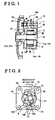
- Fig. 1 is a cross-sectional of a pump 100 according to a first embodiment of the present invention.
- Fig. 2 is a cross-sectional view taken on line II-II of Fig. 1.
- Fig. 3 is a cross-sectional view taken on line III-III of Fig. 1.
- Fig. 4 is an explanatory view showing an oil passage at which the pump 100 is provided according to a first embodiment of the present invention.
- Fig. 5 is a cross-sectional view of a pump 200 according to a second embodiment of the present invention.
- Fig. 6 is an explanatory view showing an oil passage at which a pump 300 is provided according to the second embodiment of the present invention.
- Fig. 7 is a cross-sectional view of a pump 300 according to a third embodiment of the present invention.
- Fig. 8 is a cross-sectional view of a pump 400 according to a fourth embodiment of the present invention.
- Fig. 9 is a cross-sectional view of a pump 500 according to a fifth embodiment of the present invention.
- Fig. 10 is a cross-sectional view of a pump 600 according to a sixth embodiment of the present invention.
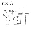
- Fig. 11 is an explanatory view showing an oil passage for directly pressure-feeding oil discharged from the first pump to a portion where the oil is supplied.
- an oil pump 100 includes a first pump 1 including a housing 30 which forms a first cylindrical space 31, a first drive rotor 50 rotatably arranged in the first cylindrical space 31, and a first driven rotor 40 positioned at an external periphery of the first drive rotor 50 and engaged with the first drive rotor 50 to rotate.
- the first drive rotor 50 is fixed to a shaft 70 positioned in the center of the first drive rotor 50.
- a drive gear 80 is fixed at a first end of the shaft 70.
- Driving force is transmitted from a driving power source through the drive gear 80 and the shaft 70 to rotate the first drive rotor 50, and thus to rotate the first driven rotor 40.
- the first driven rotor 40 and the first drive rotor 50 form plural volumetric chambers R whose capacity is increased and decreased therebetween.
- the housing 30 includes a body 10 and a cover 20.
- a discharge port 12 which is in communication with a decreasing capacity chamber of the volumetric chambers R and plural intake ports 11a, 11b which are in communication with an increasing capacity chamber of the volumetric chambers R are formed on the body 10.
- a partition 13 is formed between the intake port 11a and the intake port 11b and extends in a radial direction of the first drive rotor 50 for dividing the intake port 11a and the intake port 11b.
- the intake ports 11a, 11b are provided with intake passage s 14a, 14b which are in communication with an oil reservoir 60 respectively. Oil is sucked into the volumetric chamber R through the intake passage 14a on the intake port 11a to increase the capacity.
- volumetric chamber R By increasing the capacity of the volumetric chamber R, oil is sucked into the volumetric chamber R through the intake passage 14b on the intake port 11b. By decreasing the capacity of the volumetric chamber R, oil is pressure-fed from the volumetric chamber R to a portion to be supplied with oil through a discharge passage 15 on the discharge port 12.
- a discharge port 22 which is in communication with the decreasing capacity chamber of the volumetric chambers R and plural intake ports 21a, 21b which are in communication with the increasing capacity chamber of the volumetric chamber R are formed on the cover 20.
- the intake port 21a is in communication with the intake port 11a of the body 10 and the intake port 21b is in communication with the intake port 11b of the body 10.
- the discharge port 22 is in communication with the discharge port 12 of the body 10.
- a partition 23 is provided between the intake port 21a and the intake port 21b which are adjacent each other, and the partition 23 extends in a radial direction of the first drive rotor 50 for dividing the intake port 21a and the intake port 21b.
- the partition 23 is formed to have a configuration identical to the partition 13, faces the partition 13 and at the same position with the partition 13 in a radial direction.
- the first pump portion and the second pump portion can suck oil independently through the intake passage s 14a, 14b respectively. Accordingly, even when one of the intake passage 14a which is in communication with the oil reservoir 60 only sucks the air when the oil reservoir 60. is inclined because of driving conditions (shown in Fig. 4), oil can be sucked through the intake passage 14b without an influence by the first pump portion.
- the oil reservoirs 60, 60 are provided independently for each intake passage 14a, 14b, a common oil reservoir may be shared by the intake passages 14a, 14b.
- the first pump portion and the second pump portion can have the identical level of performance to suck oil by changing position of the partition 13, 23 to change the proportion of the capacity of the intake ports 11a, 21a to the capacity of the intake ports 11b, 21b even if the length of inner diameter of each intake passage 14a, 14b is not significantly changed.
- first oil pump 1 driving force is transmitted from a driving power source via the drive gear 80 and the shaft 70 to rotate the first drive rotor 50, and thus to rotate the first driven rotor 40.
- the capacity of the plural volumetric chambers R formed between the first driven rotor 40 and the first drive rotor 50 is changed to increase or to decrease.
- the first pump portion and the second pump portion are formed by the partitions 13, 23 formed between the intake ports 11a, 11b and the intake ports 21a, 21b respectively, and each pump portion sucks oil independently. Even when one of the intake passage 14a in communication with the oil reservoir 60 only sucks the air, oil can be sucked through the intake passage 14b.
- an oil pump 200 includes a second pump 2 in addition to the first pump 1, and the first pump 1 and the second pump 2 are driven by a shaft 270.
- a second cylindrical space 231 is formed between the first body 10 of the first pump 1 and a second cover 220, and a second body 210 (i.e., a cylindrical body having a bottom) is arranged to form the second pump 2 having a cylindrical configuration with a bottom.
- the first body 10, the second body 210 and the second cover 220 are fixed by means of a tightening member.
- Intake ports 221a, 221b corresponding to the intake ports 21a, 21b are formed at an outer bottom surface of the second body 210.
- a discharge port 222 corresponding to the discharge port 22 of the first embodiment is also formed at an external bottom surface of the second body 200.
- An intake port 211 and a discharge port 212 are formed at an inner bottom surface of the second body 210.
- an intake passage 214 which is in communication with a second oil reservoir 260 is provided at the intake port 211.
- An intake port 221A and a discharge port 222A for forming the second pump 2 are formed at the second cover 220.
- the shaft 270 extended to the opposite side of the drive gear 80 is inserted into the second cylindrical space 231.
- the shaft 270 is fixed to a second drive rotor 250.
- a second driven rotor 240 rotatably positioned in the second cylindrical space 231 is arranged at an external periphery of the second drive rotor 250.
- the second drive rotor 250 and the second driven rotor 240 are engaged to rotate and plural volumetric chambers R2 whose capacity is increased and decreased is formed between the second drive rotor 250 and the second driven rotor 240.
- the intake ports 211, 221A are in communication with an increasing capacity chambers of the volumetric chambers R2.
- the discharge port 212, 222A are in communication with a decreasing capacity chambers of the volumetric chambers R2.
- the intake port 221A is in communication with the intake port 211 and the discharge port 222A is in communication with the discharge port 212.
- the oil pump 200 can be reduced in size because the first pump 1 and the second pump 2 can be driven by the single shaft 270. Further, because bearing portions can be lubricated by means of the second pump 2, reliability can be increased.
- Other construction of the second embodiment of the present invention is identical to the construction of the first embodiment, and thus explanation is not repeated and reference numerals common to Fig, 1 are not provided in Figs. 5-6. '
- bearing portions C, D for supporting the shaft 270 is positioned on the second cover 220 and the second body 210 of the second pump 2.
- the second pump 2 is configured to constantly reserve a predetermined volume of oil in the second oil reservoir 260, and an end of the intake passage 214 is positioned in the reserved oil to securely suck the oil. Accordingly, oil is securely supplied to the bearing portions C, D by the second pump 2, thus to prevent a lack of lubrication, or the like.
- the third embodiment of the present invention includes a third cylindrical space 332.
- the third cylindrical space 332 is added to the body 210 of the second embodiment to form a third body 310.
- a third cover 320 corresponding to the third body 310 is also provided in place of the second cover 220.
- the third cover 320 is configured to have larger diameter than the second cover 220.
- the third body 310 includes a stepped recess portion having a second cylindrical space 331 and the third cylindrical space 332.
- the first driven rotor 40 and the first drive rotor 50 are inserted into the second cylindrical space 331.
- the second body 210 of the second pump 2 is positioned in the third cylindrical space 332.
- the diameter of the third cylindrical space 332 is longer than the diameter of the first cylindrical space 31.
- Position of the second body 210 and the cover 320 in a peripheral direction is defined by a pin 315.
- Other construction is identical to the construction of the second embodiment, thus, the explanation is not repeated and the same reference numeral is not repeated.
- An oil pump 400 includes a single recessed cylindrical space 430 which is configured to have a recess portion at the cylindrical space of the body 210 of the second embodiment, and a first cylindrical space 431 and a second cylindrical space 432 are provided at the recessed cylindrical space 430.
- a circular body 434 is provided between the first cylindrical space 431 and the second cylindrical space 432.
- Intake ports 411a, 411b and a discharge port 412 are formed on a first side of the circular body 434. Intake ports 411A and a discharge. port 412A are positioned at a second side of the circular body 434. Position of the circular body 434 in a peripheral direction is fixed by a fixing means.
- a separate member can be applied as the circular body 434.
- the circular body 434 using material suitable for bearings, reliability of the oil pump 400 can be increased.
- Other construction of the fourth embodiment is identical to the second embodiment, and thus the explanation is not repeated and reference numeral in Fig. 8 is not repeated.
- An oil pump 500 includes a discharge port 512 and a discharge port 522 which are configured by connecting the discharge port 212 and the discharge port 222 of the second embodiment to be penetrated through each other. With the foregoing construction, oil discharged from the discharge port 522 is discharged through a discharge passage 515 which is arranged in communication with the discharge port 512.
- a portion of oil discharged from the second pump 2 is supplied to the first pump 1 through the discharge port 522 of the first pump 1. Accordingly, sufficient oil is supplied to the first pump 1 even when non-lubrication state has continued because the first pump 1 sucks the air, each member of the first pump 1 can be lubricated and reliability of lubricated portion of sliding portion can be increased.
- Other construction of the fifth embodiment is identical to the second embodiment, and thus the explanation is not repeated, and reference numeral is no repeated.
- An oil pump 600 includes the discharge passage 515 of the fifth embodiment which is positioned on the first pump 1 at opposite side of the second pump 2.
- Oil discharged from the first pump 1 may be directly pressure-fed to a portion to be supplied with oil as shown in Fig. 11.
- Other construction of the sixth embodiment is identical to the fifth embodiment, and thus the explanation is not repeated, and the same reference numeral is not repeated.
- the partition extended toward the outside of the first drive rotor and for dividing adjacent intake ports is formed between the adjacent intake ports of the plural intake ports, and the independent intake passage which is in communication with the oil reservoir is provided at each intake port.
- oil can be independently sucked from plural portions with a single rotor, and the construction of the oil pump can be simplified. Further, even when the air is sucked from one of the intake ports, oil can be sucked from the rest, of the intake ports, and thus, sliding portions between the housing and the rotor can be lubricated, and the abrasion can be prevented. Because a dimension of the rotor where the rotor and the housing slides can be reduced, reliability is increased, and friction can be reduced.
- the second pump which includes the second drive rotor rotatably positioned in the second cylindrical space, and the second driven rotor positioned around the external periphery of the second drive rotor and engaged with the second drive rotor to rotate are arranged on the rotational axis where the first drive rotor of the first pump inducing the first drive rotor and the first driven rotor is rotated, the first pump and the second pump can be rotated by a single shaft, and thus the oil pump can be reduced in size.
- the second pump By lubricating bearing portions by the second pump, the reliability of the bearing portions can be increased.
- the cylindrical body having a bottom to which one of the first cylindrical space or the second cylindrical space is formed is arranged between the first pump and the second pump, the first pump and the second pump can be assembled from a single direction, which is axial direction.
- the oil pump including the first pump and the second pump can be reduced in size.
- the circular body may be made as a separate member and may be made of material suitable for bearings, the reliability of the oil pump can be increased, and the first pump and the second pump can be assembled from a single direction, which is axial direction.
- the discharge port of the first pump and the discharge port of the second pump are combined to penetrate through each other to communicate each other and share the common discharge passage, oil discharged from the second pump can be supplied to between each element of the first pump, each element of the first pump can be lubricated, and the reliability of the sliding portions can be increased.
- the discharge port of the first pump and the discharge port of the second pump are combined to penetrate through each other to communicate each other and share the common discharge passage, and the common discharge passage is provided on the discharge port of the first pump at the opposite side of the second pump, oil discharged from the second pump can be securely supplied to each element of the first pump at the entire region of at the opposite side of the second pump, each element of the first pump can be lubricated, and the reliability of the sliding portion can be increased.
Landscapes
- Engineering & Computer Science (AREA)
- Mechanical Engineering (AREA)
- General Engineering & Computer Science (AREA)
- Details And Applications Of Rotary Liquid Pumps (AREA)
- Rotary Pumps (AREA)
Abstract
Description
- The present invention relates to an oil pump. More particularly, the present invention pertains to an oil pump which enables to suck oil from each intake portion independently without being influenced by resistance.
- A known oil pump includes a first pump (i.e., a scavenge pump) for supplying oil in an oil pan to a reserve tank and a second pump (i.e., a feed pump) for supplying oil in the reserve tank to lubrication portion. The first pump of the oil pump is provided with plural rotors arranged on a common axis line and each having inlet which is in communication with the oil pan, and a spacer positioned between the rotors and having a discharge passage which is commonly used by rotors arranged adjacent each other. With the foregoing construction, oil is supplied to each rotor of the first pump through the plural inlets in the oil pan. Thus, in case at least one of the inlets is in the oil of the oil pan, the first pump functions even when other inlets are not placed in the oil and suck air (e.g., described in JPH06 (1994)-94805B).
- Notwithstanding, with the foregoing construction, in order to provide plural numbers of the inlets, plural rotors are required to be provided for respective inlets. This makes the oil pump have longer length in an axial direction. Further, when the inlet sucks only the air, oil is not sucked into a particular rotor, the rotor is left without lubrication, and abrasion is likely generated between a drive rotor and a casing into which a driven rotor is inserted, which decreases reliability of the oil pump.
- A need thus exists for an oil pump which ensures reliability by preventing non-lubrication of the oil pump, which has possibility to suck the air from an inlet, and reduces the oil pump in size.
- In light of the foregoing, the present invention provides an oil pump, which includes a first cylindrical space, a first drive rotor rotatably positioned in the first cylindrical space, a first driven rotor positioned at an external periphery of the first drive rotor in the first cylindrical space, and engaged with the first drive rotor to rotate, a plurality of volumetric chambers formed between the first drive rotor and the first driven rotor, the volumetric chambers are configured to increase and decrease capacity during the rotation of the first drive rotor and first driven rotor, a discharge port being in communication with at least one of the volumetric chambers where capacity is decreasing, a plurality of intake port being in communication with at least one of the volumetric chambers where capacity is increasing, characterized by including a partition provided between adjacent intake ports of the plural intake ports for dividing the intake ports adjacent each other, and an intake passage provided at each intake port, the intake port being independently in communication with an oil reservoir.
- According to the present invention, the partition for dividing adjacent intake ports is formed between the adjacent intake ports of the plural intake ports, and the independent intake passage which is in communication with the oil reservoir is provided at each intake port. Thus, oil can be independently sucked from plural portions with a single rotor, and the construction of the oil pump can be simplified. Further, even when the air is sucked from one of the intake ports, oil can be sucked from the rest of the intake ports, and thus, sliding portions between a housing and the rotor can be lubricated, and the abrasion can be prevented. Because a dimension of the rotor where the rotor and the housing slides can be reduced, reliability is increased, and friction can be reduced.
- The foregoing and additional features and characteristics of the present invention will become more apparent from the following detailed description considered with reference to the accompanying drawings, wherein:
- Fig. 1 is a cross-sectional of a
pump 100 according to a first embodiment of the present invention. - Fig. 2 is a cross-sectional view taken on line II-II of Fig. 1.
- Fig. 3 is a cross-sectional view taken on line III-III of Fig. 1.
- Fig. 4 is an explanatory view showing an oil passage at which the
pump 100 is provided according to a first embodiment of the present invention. - Fig. 5 is a cross-sectional view of a
pump 200 according to a second embodiment of the present invention. - Fig. 6 is an explanatory view showing an oil passage at which a
pump 300 is provided according to the second embodiment of the present invention. - Fig. 7 is a cross-sectional view of a
pump 300 according to a third embodiment of the present invention. - Fig. 8 is a cross-sectional view of a
pump 400 according to a fourth embodiment of the present invention. - Fig. 9 is a cross-sectional view of a
pump 500 according to a fifth embodiment of the present invention. - Fig. 10 is a cross-sectional view of a
pump 600 according to a sixth embodiment of the present invention. - Fig. 11 is an explanatory view showing an oil passage for directly pressure-feeding oil discharged from the first pump to a portion where the oil is supplied.
- Embodiments of the present invention will be explained with reference to illustrations of drawing figures as follows.
- A first embodiment of the present invention will be explained referring to Figs. 1-3. As shown in Fig. 1, an
oil pump 100 includes afirst pump 1 including ahousing 30 which forms a firstcylindrical space 31, afirst drive rotor 50 rotatably arranged in the firstcylindrical space 31, and a first drivenrotor 40 positioned at an external periphery of thefirst drive rotor 50 and engaged with thefirst drive rotor 50 to rotate. Thefirst drive rotor 50 is fixed to ashaft 70 positioned in the center of thefirst drive rotor 50. Adrive gear 80 is fixed at a first end of theshaft 70. Driving force is transmitted from a driving power source through thedrive gear 80 and theshaft 70 to rotate thefirst drive rotor 50, and thus to rotate the first drivenrotor 40. As shown in Fig. 2, the first drivenrotor 40 and thefirst drive rotor 50 form plural volumetric chambers R whose capacity is increased and decreased therebetween. - The
housing 30 includes abody 10 and acover 20. - As shown in Fig. 2, a
discharge port 12 which is in communication with a decreasing capacity chamber of the volumetric chambers R andplural intake ports body 10. Apartition 13 is formed between theintake port 11a and theintake port 11b and extends in a radial direction of thefirst drive rotor 50 for dividing theintake port 11a and theintake port 11b. As shown in Figs. 2 and 4, theintake ports oil reservoir 60 respectively. Oil is sucked into the volumetric chamber R through theintake passage 14a on theintake port 11a to increase the capacity. By increasing the capacity of the volumetric chamber R, oil is sucked into the volumetric chamber R through theintake passage 14b on theintake port 11b. By decreasing the capacity of the volumetric chamber R, oil is pressure-fed from the volumetric chamber R to a portion to be supplied with oil through adischarge passage 15 on thedischarge port 12. - As shown in Fig. 3, a
discharge port 22 which is in communication with the decreasing capacity chamber of the volumetric chambers R andplural intake ports cover 20. Theintake port 21a is in communication with theintake port 11a of thebody 10 and theintake port 21b is in communication with theintake port 11b of thebody 10. Thedischarge port 22 is in communication with thedischarge port 12 of thebody 10. Apartition 23 is provided between theintake port 21a and theintake port 21b which are adjacent each other, and thepartition 23 extends in a radial direction of thefirst drive rotor 50 for dividing theintake port 21a and theintake port 21b. Thepartition 23 is formed to have a configuration identical to thepartition 13, faces thepartition 13 and at the same position with thepartition 13 in a radial direction. By increasing the capacity of the volumetric chamber R, oil is sucked into the volumetric chamber R through theintake passage 14a on theintake port 21a. By increasing the capacity of the volumetric chamber R, oil is sucked into the volumetric chamber R through theintake passage 14b on theintake port 21b. By decreasing the capacity of the volumetric chamber R, oil is pressure-fed to a portion to be supplied with oil through thedischarge passage 15 on thedischarge port 22. - As explained above, because a first pump portion including the
intake ports intake ports partitions intake passage 14a which is in communication with theoil reservoir 60 only sucks the air when theoil reservoir 60. is inclined because of driving conditions (shown in Fig. 4), oil can be sucked through theintake passage 14b without an influence by the first pump portion. Although theoil reservoirs intake passage intake passages - When arrangement of the
oil reservoir 60 gives restrictions, and a distance from theoil reservoir 60 to eachintake passage intake passages partition intake ports intake ports intake passage - An operation of the embodiment of the present invention will be explained as follows.
- With the
first oil pump 1, driving force is transmitted from a driving power source via thedrive gear 80 and theshaft 70 to rotate thefirst drive rotor 50, and thus to rotate the first drivenrotor 40. In accordance with the rotation of thefirst drive rotor 50 and the first drivenrotor 40, the capacity of the plural volumetric chambers R formed between the first drivenrotor 40 and thefirst drive rotor 50 is changed to increase or to decrease. In this circumstance, the first pump portion and the second pump portion are formed by thepartitions intake ports intake ports intake passage 14a in communication with theoil reservoir 60 only sucks the air, oil can be sucked through theintake passage 14b. - A second embodiment of the present invention will be explained with reference to Fig. 5. As shown in Fig. 5, an
oil pump 200 according to the second embodiment of the present invention includes asecond pump 2 in addition to thefirst pump 1, and thefirst pump 1 and thesecond pump 2 are driven by ashaft 270. Further, with the construction of the second embodiment of the present invention, a secondcylindrical space 231 is formed between thefirst body 10 of thefirst pump 1 and asecond cover 220, and a second body 210 (i.e., a cylindrical body having a bottom) is arranged to form thesecond pump 2 having a cylindrical configuration with a bottom. Thefirst body 10, thesecond body 210 and thesecond cover 220 are fixed by means of a tightening member. -
Intake ports intake ports second body 210. Adischarge port 222 corresponding to thedischarge port 22 of the first embodiment is also formed at an external bottom surface of thesecond body 200. Anintake port 211 and adischarge port 212 are formed at an inner bottom surface of thesecond body 210. As shown in Figs. 5-6, anintake passage 214 which is in communication with asecond oil reservoir 260 is provided at theintake port 211. - An
intake port 221A and adischarge port 222A for forming thesecond pump 2 are formed at thesecond cover 220. - The
shaft 270 extended to the opposite side of thedrive gear 80 is inserted into the secondcylindrical space 231. Theshaft 270 is fixed to asecond drive rotor 250. A second drivenrotor 240 rotatably positioned in the secondcylindrical space 231 is arranged at an external periphery of thesecond drive rotor 250. Thesecond drive rotor 250 and the second drivenrotor 240 are engaged to rotate and plural volumetric chambers R2 whose capacity is increased and decreased is formed between thesecond drive rotor 250 and the second drivenrotor 240. - The
intake ports discharge port intake port 221A is in communication with theintake port 211 and thedischarge port 222A is in communication with thedischarge port 212. - With the-construction according to the second embodiment of the present invention, the
oil pump 200 can be reduced in size because thefirst pump 1 and thesecond pump 2 can be driven by thesingle shaft 270. Further, because bearing portions can be lubricated by means of thesecond pump 2, reliability can be increased. Other construction of the second embodiment of the present invention is identical to the construction of the first embodiment, and thus explanation is not repeated and reference numerals common to Fig, 1 are not provided in Figs. 5-6. ' - According to the second embodiment of the present invention, bearing portions C, D for supporting the
shaft 270 is positioned on thesecond cover 220 and thesecond body 210 of thesecond pump 2. Thesecond pump 2 is configured to constantly reserve a predetermined volume of oil in thesecond oil reservoir 260, and an end of theintake passage 214 is positioned in the reserved oil to securely suck the oil. Accordingly, oil is securely supplied to the bearing portions C, D by thesecond pump 2, thus to prevent a lack of lubrication, or the like. - A third embodiment of the present invention will be explained with reference to Fig. 7. The third embodiment of the present invention includes a third
cylindrical space 332. The thirdcylindrical space 332 is added to thebody 210 of the second embodiment to form athird body 310. Athird cover 320 corresponding to thethird body 310 is also provided in place of thesecond cover 220. Thethird cover 320 is configured to have larger diameter than thesecond cover 220. - The
third body 310 includes a stepped recess portion having a secondcylindrical space 331 and the thirdcylindrical space 332. The first drivenrotor 40 and thefirst drive rotor 50 are inserted into the secondcylindrical space 331. Thesecond body 210 of thesecond pump 2 is positioned in the thirdcylindrical space 332. The diameter of the thirdcylindrical space 332 is longer than the diameter of the firstcylindrical space 31. Position of thesecond body 210 and thecover 320 in a peripheral direction is defined by apin 315. Other construction is identical to the construction of the second embodiment, thus, the explanation is not repeated and the same reference numeral is not repeated.. - A fourth embodiment of the present invention will be explained with reference to Fig. 8. An
oil pump 400 includes a single recessedcylindrical space 430 which is configured to have a recess portion at the cylindrical space of thebody 210 of the second embodiment, and a firstcylindrical space 431 and a secondcylindrical space 432 are provided at the recessedcylindrical space 430. Acircular body 434 is provided between the firstcylindrical space 431 and the secondcylindrical space 432. -
Intake ports discharge port 412 are formed on a first side of thecircular body 434.Intake ports 411A and a discharge.port 412A are positioned at a second side of thecircular body 434. Position of thecircular body 434 in a peripheral direction is fixed by a fixing means. - With the construction according to the fourth embodiment of the present invention, a separate member can be applied as the
circular body 434. For example, by forming thecircular body 434 using material suitable for bearings, reliability of theoil pump 400 can be increased. Other construction of the fourth embodiment is identical to the second embodiment, and thus the explanation is not repeated and reference numeral in Fig. 8 is not repeated. - A fifth embodiment of the present invention will be explained with reference to Fig. 9. An
oil pump 500 includes adischarge port 512 and adischarge port 522 which are configured by connecting thedischarge port 212 and thedischarge port 222 of the second embodiment to be penetrated through each other. With the foregoing construction, oil discharged from thedischarge port 522 is discharged through adischarge passage 515 which is arranged in communication with thedischarge port 512. - With the construction according to the fifth embodiment, a portion of oil discharged from the
second pump 2 is supplied to thefirst pump 1 through thedischarge port 522 of thefirst pump 1. Accordingly, sufficient oil is supplied to thefirst pump 1 even when non-lubrication state has continued because thefirst pump 1 sucks the air, each member of thefirst pump 1 can be lubricated and reliability of lubricated portion of sliding portion can be increased. Other construction of the fifth embodiment is identical to the second embodiment, and thus the explanation is not repeated, and reference numeral is no repeated. - A sixth embodiment of the present invention will be explained as follows. An
oil pump 600 includes thedischarge passage 515 of the fifth embodiment which is positioned on thefirst pump 1 at opposite side of thesecond pump 2. - Accordingly, a part of oil discharged from the
second pump 2 is supplied to the entirefirst pump 1 in the axial direction through thedischarge port 522 of thefirst pump 1. Thus, sufficient oil is supplied to thefirst pump 1 even when thefirst pump 1 sucks the air, and thus drawbacks because of a lack of lubrication between each member of thefirst pump 1 can be securely prevented. - Oil discharged from the
first pump 1 may be directly pressure-fed to a portion to be supplied with oil as shown in Fig. 11. Other construction of the sixth embodiment is identical to the fifth embodiment, and thus the explanation is not repeated, and the same reference numeral is not repeated. - According to the embodiment of the present invention, the partition extended toward the outside of the first drive rotor and for dividing adjacent intake ports is formed between the adjacent intake ports of the plural intake ports, and the independent intake passage which is in communication with the oil reservoir is provided at each intake port. Thus, oil can be independently sucked from plural portions with a single rotor, and the construction of the oil pump can be simplified. Further, even when the air is sucked from one of the intake ports, oil can be sucked from the rest, of the intake ports, and thus, sliding portions between the housing and the rotor can be lubricated, and the abrasion can be prevented. Because a dimension of the rotor where the rotor and the housing slides can be reduced, reliability is increased, and friction can be reduced.
- According to the embodiment of the present invention, because the second pump which includes the second drive rotor rotatably positioned in the second cylindrical space, and the second driven rotor positioned around the external periphery of the second drive rotor and engaged with the second drive rotor to rotate are arranged on the rotational axis where the first drive rotor of the first pump inducing the first drive rotor and the first driven rotor is rotated, the first pump and the second pump can be rotated by a single shaft, and thus the oil pump can be reduced in size. By lubricating bearing portions by the second pump, the reliability of the bearing portions can be increased.
- According to the embodiment of the present invention, because the cylindrical body having a bottom to which one of the first cylindrical space or the second cylindrical space is formed is arranged between the first pump and the second pump, the first pump and the second pump can be assembled from a single direction, which is axial direction.
- According to the embodiment of the present invention, by positioning the circular body for dividing the first pump and the second pump between the first pump and the second pump, the oil pump including the first pump and the second pump can be reduced in size. The circular body may be made as a separate member and may be made of material suitable for bearings, the reliability of the oil pump can be increased, and the first pump and the second pump can be assembled from a single direction, which is axial direction.
- According to the embodiment of the present invention, because the discharge port of the first pump and the discharge port of the second pump are combined to penetrate through each other to communicate each other and share the common discharge passage, oil discharged from the second pump can be supplied to between each element of the first pump, each element of the first pump can be lubricated, and the reliability of the sliding portions can be increased.
- According to the embodiment of the present invention, because the discharge port of the first pump and the discharge port of the second pump are combined to penetrate through each other to communicate each other and share the common discharge passage, and the common discharge passage is provided on the discharge port of the first pump at the opposite side of the second pump, oil discharged from the second pump can be securely supplied to each element of the first pump at the entire region of at the opposite side of the second pump, each element of the first pump can be lubricated, and the reliability of the sliding portion can be increased.
It is explicitly stated that all features disclosed in the description and/or the claims are intended to be disclosed separately and independently from each other for the purpose of original disclosure as well as for the purpose of restricting the claimed invention independent of the composition of the features in the embodiments and/or the claims. It is explicitly stated that all value ranges or indications of groups of entities disclose every possible intermediate value or intermediate entity for the purpose of original disclosure as well as for the purpose of restricting the claimed invention, in particular as limits of value ranges.
Claims (9)
- An oil pump (100, 200, 300, 400; 500, 600) comprising:a first cylindrical space (31, 431);a first drive rotor (50) rotatably positioned in the first cylindrical space;a first driven rotor (40) positioned at an external periphery of the first drive rotor in the first cylindrical space, and engaged with the first drive rotor to rotate;a plurality of volumetric chambers (R) formed between the first drive rotor and the firstdriven rotor, the volumetric chambers are coafigured to increase and decrease capacity during the rotation of the first drive rotor and the first driven rotor;a discharge port (12) being in communication with at least one of the volumetric chambers where capacity is decreasing;a plurality of intake port (11a, 11b) being in communication with at least one of the volumetric chambers where capacity is increasing; characterized by comprisinga partition (13, 23) provided between adjacent intake ports of the plural intake ports for dividing the intake ports adjacent each other; andan intake passage (14a, 14b) provided at each intake port, the intake port being independently in communication with an oil reservoir.
- The oil pump according to Claim 1, wherein the partition extends toward the outside of the first drive rotor.
- The oil pump according to Claims 1-2, further comprising:a first pump (1) including the first drive rotor and the first driven rotor; anda second pump (2) including a second cylinder space (231), a second drive rotor (250) rotatably positioned in the second cylindrical space, and a second driven rotor (240) positioned at an external periphery of the second drive rotor in the second cylindrical space, and engaged with the second drive rotor to rotate; whereinthe second drive rotor is positioned on a rotational axis for rotating the first drive rotor.
- The oil pump according to Claim 3, further comprising:a cylindrical body (210) having a bottom at which at least either one of the first cylindrical space or the second cylindrical space are provided, the cylindrical body being positioned between the first pump and the second pump.
- The oil pump according to Claim 4, further comprising:a first body (10) for forming the first cylindrical space;a second body (210) for forming the second cylindrical space; whereinthe first body includes a third cylindrical space (332) which is in communication with the first cylindrical space; andthe second body (331) having the cylindrical body with the bottom is positioned in the third cylindrical space.
- The oil pump according to Claim 3, further comprising:a circular body (434) provided between the first pump and the second pump for dividing the first pump and the second pump.
- The oil pump according to Claim 6, further comprising:a cylindrical space (430) where the first pump and the second pump are positioned; wherein the circular body divides the cylindrical space into the first cylindrical space (431) and the second cylindrical space (432).
- The oil pump according to Claims 3-7, wherein the discharge port of the first pump and the discharge port of the second pump are connected to penetrate through each other to establish communication each other, and includes a common discharge passage (515).
- The oil pump according to Claim 8 wherein the common discharge passage is positioned on the discharge port of the first pump at opposite side of the second pump.
Applications Claiming Priority (1)
| Application Number | Priority Date | Filing Date | Title |
|---|---|---|---|
| JP2004312324A JP2006125239A (en) | 2004-10-27 | 2004-10-27 | Oil pump |
Publications (1)
| Publication Number | Publication Date |
|---|---|
| EP1653081A1 true EP1653081A1 (en) | 2006-05-03 |
Family
ID=35733829
Family Applications (1)
| Application Number | Title | Priority Date | Filing Date |
|---|---|---|---|
| EP05022612A Withdrawn EP1653081A1 (en) | 2004-10-27 | 2005-10-17 | Oil pump |
Country Status (2)
| Country | Link |
|---|---|
| EP (1) | EP1653081A1 (en) |
| JP (1) | JP2006125239A (en) |
Families Citing this family (4)
| Publication number | Priority date | Publication date | Assignee | Title |
|---|---|---|---|---|
| JP2009215932A (en) * | 2008-03-10 | 2009-09-24 | Hitachi Ltd | Tandem pump and tandem pump for brake devices |
| JP5198300B2 (en) * | 2009-01-22 | 2013-05-15 | 株式会社山田製作所 | Oil pump |
| JP5878786B2 (en) * | 2012-02-21 | 2016-03-08 | 株式会社ミクニ | Oil pump |
| CN109869240B (en) * | 2017-12-01 | 2021-03-05 | 空客直升机 | Internal combustion engine with at least one dry sump type crankcase |
Citations (4)
| Publication number | Priority date | Publication date | Assignee | Title |
|---|---|---|---|---|
| GB596064A (en) * | 1945-07-17 | 1947-12-24 | Stothert & Pitt Ltd | Improvements in or relating to rotary pumps |
| JPH03237207A (en) * | 1989-10-31 | 1991-10-23 | Isuzu Motors Ltd | Lubricating device for engine |
| US20040161355A1 (en) * | 2003-02-18 | 2004-08-19 | Harley-Davidson Motor Company Group, Inc. | Reduced friction gerotor |
| US20040191074A1 (en) * | 2003-03-31 | 2004-09-30 | Denso Corporation | Fuel injection pump |
-
2004
- 2004-10-27 JP JP2004312324A patent/JP2006125239A/en active Pending
-
2005
- 2005-10-17 EP EP05022612A patent/EP1653081A1/en not_active Withdrawn
Patent Citations (4)
| Publication number | Priority date | Publication date | Assignee | Title |
|---|---|---|---|---|
| GB596064A (en) * | 1945-07-17 | 1947-12-24 | Stothert & Pitt Ltd | Improvements in or relating to rotary pumps |
| JPH03237207A (en) * | 1989-10-31 | 1991-10-23 | Isuzu Motors Ltd | Lubricating device for engine |
| US20040161355A1 (en) * | 2003-02-18 | 2004-08-19 | Harley-Davidson Motor Company Group, Inc. | Reduced friction gerotor |
| US20040191074A1 (en) * | 2003-03-31 | 2004-09-30 | Denso Corporation | Fuel injection pump |
Non-Patent Citations (1)
| Title |
|---|
| PATENT ABSTRACTS OF JAPAN vol. 016, no. 021 (M - 1201) 20 January 1992 (1992-01-20) * |
Also Published As
| Publication number | Publication date |
|---|---|
| JP2006125239A (en) | 2006-05-18 |
Similar Documents
| Publication | Publication Date | Title |
|---|---|---|
| CN103883495B (en) | Electrodynamic pump | |
| KR100840915B1 (en) | Swash plate compressor | |
| KR101280978B1 (en) | Vane pump | |
| CN107795480B (en) | Internal gear oil pump assembly | |
| US9638190B2 (en) | Oil pump | |
| EP2918839B1 (en) | Electric pump | |
| JPH0694805B2 (en) | Engine lubricator | |
| JP2019011745A (en) | Electric oil pump | |
| WO2021142525A1 (en) | System for transporting lubricating oil in a compressor | |
| JP6444166B2 (en) | Variable displacement pump | |
| US20120034125A1 (en) | Vane pump with improved rotor and vane extension ring | |
| JP2009174448A (en) | Fluid pump | |
| JP7476059B2 (en) | Valve plates, cylinder blocks, hydraulic pumps and motors | |
| JP2009287463A (en) | Pump | |
| JP2006200409A (en) | Balancer device for internal combustion engine | |
| CN106968946A (en) | Vehicle hydraulic device | |
| US12546312B2 (en) | Oil pump for a motor vehicle | |
| JP3011796B2 (en) | Internal gear pump for hydraulic fluid | |
| US6715986B2 (en) | Fuel pump | |
| JP2006125239A (en) | Oil pump | |
| US12264673B2 (en) | Electronic positive displacement fluid pump with motor cooling and air purging | |
| CN116464892A (en) | Oil supply system for power unit of machine and power unit including the oil supply system | |
| JP2006118424A (en) | Vacuum pump | |
| WO2022176544A1 (en) | Tandem-type oil pump | |
| US7267524B2 (en) | Fuel pump having single sided impeller |
Legal Events
| Date | Code | Title | Description |
|---|---|---|---|
| PUAI | Public reference made under article 153(3) epc to a published international application that has entered the european phase |
Free format text: ORIGINAL CODE: 0009012 |
|
| AK | Designated contracting states |
Kind code of ref document: A1 Designated state(s): AT BE BG CH CY CZ DE DK EE ES FI FR GB GR HU IE IS IT LI LT LU LV MC NL PL PT RO SE SI SK TR |
|
| AX | Request for extension of the european patent |
Extension state: AL BA HR MK YU |
|
| 17P | Request for examination filed |
Effective date: 20061006 |
|
| 17Q | First examination report despatched |
Effective date: 20061103 |
|
| AKX | Designation fees paid |
Designated state(s): AT BE BG CH CY CZ DE DK EE ES FI FR GB GR HU IE IS IT LI LT LU LV MC NL PL PT RO SE SI SK TR |
|
| STAA | Information on the status of an ep patent application or granted ep patent |
Free format text: STATUS: THE APPLICATION IS DEEMED TO BE WITHDRAWN |
|
| 18D | Application deemed to be withdrawn |
Effective date: 20070314 |