EP1652986A1 - Sewing machine - Google Patents
Sewing machine Download PDFInfo
- Publication number
- EP1652986A1 EP1652986A1 EP05023417A EP05023417A EP1652986A1 EP 1652986 A1 EP1652986 A1 EP 1652986A1 EP 05023417 A EP05023417 A EP 05023417A EP 05023417 A EP05023417 A EP 05023417A EP 1652986 A1 EP1652986 A1 EP 1652986A1
- Authority
- EP
- European Patent Office
- Prior art keywords
- frame
- pillar
- inner space
- arm
- base
- Prior art date
- Legal status (The legal status is an assumption and is not a legal conclusion. Google has not performed a legal analysis and makes no representation as to the accuracy of the status listed.)
- Granted
Links
Images




Classifications
-
- D—TEXTILES; PAPER
- D05—SEWING; EMBROIDERING; TUFTING
- D05B—SEWING
- D05B73/00—Casings
Definitions
- This invention generally relates to a sewing machine. More particularly, this invention pertains to an internal structure of a casing of a sewing machine.
- a known sewing machine includes a sewing mechanism within a casing.
- JP2003-169989 discloses a sewing mechanism supported within a reinforced resin casing.
- the sewing mechanism is supported within the reinforced resin casing and thus the casing is stable even if vibration is generated by the sewing mechanism at a time that the sewing machine is operated. For example, problems such as fluctuation in a position of a needle as it penetrates into a fabric may be prevented.
- a sewing machine including a resin casing constituted by integral molding of a base portion, a pillar portion extending upward from one end of the base portion, and an arm portion extending from the pillar portion so as to be located over the base portion, and a sewing mechanism having a sewing function and accommodated in an inner space formed by a first inner space of the base portion, a second inner space of the pillar portion, and a third inner space of the arm portion connected to one another characterized in that the sewing mechanism is accommodated within the frame so as to be supported by a frame member, made up of a base frame that has been pressed and faces the base portion, a pillar frame that has been pressed and is assembled on one end of the base frame so as to face the pillar portion, and an arm frame that has been pressed and is assembled on the pillar frame so as to face the arm portion.
- the sewing mechanism is supported by the frame member including three divided frames that have been pressed.
- the resin casing is freed from the need for a vibration resistance structure in relation to the sewing mechanism, and the structure of the sewing machine may thereby be simplified.
- Fig. 1 is a schematic view of an inside of a casing of a sewing machine according to an embodiment of the present invention
- Fig. 2 is a perspective view of the casing of the sewing machine shown in Fig. 1;
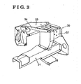
- Fig. 3 is a perspective view of a frame member accommodated in the casing shown in Fig. 2;
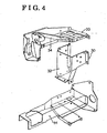
- Fig. 4 is an exploded perspective view of the frame member shown in Fig. 3;
- Fig. 5 is a side view for illustrating a state in which an upper shaft unit is assembled onto an arm frame of the frame member shown in Figs. 3 and 4;
- Fig. 6 is a plane view of a state shown in Fig. 5.
- Fig. 7 is a side view of a state shown in Fig. 5 as viewed from the left side;
- Fig. 8 is a plane view for illustrating a state in which a lower shaft unit is assembled onto a base frame of the frame member shown in Figs. 3 and 4;
- Fig. 9 is a front view of the state shown in Fig. 8.
- Fig. 10 is a side view of the state shown in Fig. 8 as viewed from the right side;
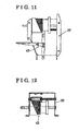
- Fig. 11 is a side view for illustrating a state in which a pattern generation unit is assembled onto a pillar frame of the frame member shown in Figs. 3 and 4;
- Fig. 12 is a plane view of the state shown in Fig. 11;
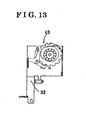
- Fig. 13 is a perspective view of the state shown in Fig. 5.
- a sewing machine 10 includes a resin casing 20.
- the resin casing 20 is constituted by integral molding of a base portion 21 placed on a workbench (not shown), a pillar portion 22 extending upward from one end of the base portion 21, and an arm portion 23 extending from the pillar portion 22 so as to be located over the base portion 21, or opposed to the base portion 21.
- An inner space 25 of the resin casing 20 is formed by a first inner space 26 of the base portion 21, a second inner space 27 of the pillar portion 22, and a third inner space 28 of the arm portion 23, connected to one another so as to define a single space.
- the inner space 25 of the resin casing 20 is in an open state but in practice the open side of the inner space 25 is covered by a cover member (not shown).
- a sewing mechanism 40 having a sewing function and supported by a frame member 30 as shown in Figs. 1, 3 and 4, is accommodated in the inner space 25 of the resin casing 20.
- the frame member 30 is made up of three frames, i.e. a base frame 31, a pillar frame 32 and an arm frame 33, formed by pressing of a steel plate.
- the frame member 30 is protected by the rigidity of its structure from the effects of vibration of the sewing mechanism 40.
- the base frame 31, the pillar frame 32, and the arm frame 33 of the frame member 30 are accommodated respectively in the first inner space 26 of the base portion 21, the second inner space 27 of the pillar portion 22, and the third inner space 28 of the arm portion 23.
- the arm frame 33 is assembled onto the pillar frame 32 in a cantilever manner as shown in Fig. 4.
- the arm frame 33 is horizontally asymmetrical and vertically uneven.
- a tip end portion formed on an upper side of the arm frame 33 and a base portion formed on a lower side of the arm frame 33 are connected to each other by means of a beam member 34.
- the three frames i.e. the base frame 31, the pillar frame 32, and the arm frame 33, are assembled in the following manner. First, holes are formed on respective overlapping fitting portions of adjacent frames. Then, each screw (not shown) is screwed into two holes facing each other.
- Such an assembly method i.e. connecting structure, is known and thus a detailed explanation is omitted.
- a deflection portion may not exist between the base frame 31 and the pillar frame 32, or between the pillar frame 32 and the arm frame 33.
- frame member 30 may have high deflection rigidity.
- the connecting structure may also be achieved by a means such as welding, riveting, or fitting, instead of screwing.
- the sewing mechanism 40 includes an upper shaft mechanism, a lower shaft mechanism, and a pattern generation mechanism, as is a known structure.
- the upper shaft mechanism, the lower shaft mechanism, and the pattern generation mechanism are unitized respectively as an upper shaft unit 41, a lower shaft unit 42, and a pattern generation unit 43.
- the upper shaft unit 41 is arranged and supported within the arm frame 33.
- the lower shaft unit 42 is arranged and supported within the base frame 31.
- the pattern generation unit 43 is arranged and supported within the pillar frame 32, as shown in Figs. 11 to 13.
- the arm frame 33, the base frame 31, or the pillar frame 32 may be replaced by another arm frame, another base frame, or another pillar frame respectively equipped with an upper shaft unit, a lower shaft unit, and a pattern generation unit, such that such the specification change may be achieved in a simple manner.
- a sewing machine (10) including a resin casing (20) constituted by integral molding of a base portion (21), a pillar portion (22), and an arm portion (23), and a sewing mechanism (40) having a sewing function and accommodated in an inner space (25) formed by a first inner space (26) of the base portion, a second inner space (27) of the pillar portion, and a third inner space (28) of the arm portion connected to one another characterized in that the sewing mechanism is accommodated within the frame so as to be supported by a frame member (30), made up of a base frame (31) that has been pressed and faces the base portion, a pillar frame (32) that has been pressed and is assembled on one end of the base frame so as to face the pillar portion, and an arm frame (33) that has been pressed and is assembled on the pillar frame so as to face the arm portion.
- a frame member (30) made up of a base frame (31) that has been pressed and faces the base portion, a pillar frame (32) that has been pressed and is assembled on one
Landscapes
- Engineering & Computer Science (AREA)
- Textile Engineering (AREA)
- Sewing Machines And Sewing (AREA)
Abstract
Description
- This invention generally relates to a sewing machine. More particularly, this invention pertains to an internal structure of a casing of a sewing machine.
- A known sewing machine includes a sewing mechanism within a casing. JP2003-169989 discloses a sewing mechanism supported within a reinforced resin casing.
- According to the sewing machine disclosed, the sewing mechanism is supported within the reinforced resin casing and thus the casing is stable even if vibration is generated by the sewing mechanism at a time that the sewing machine is operated. For example, problems such as fluctuation in a position of a needle as it penetrates into a fabric may be prevented.
- In order to reinforce a resin casing against vibration, i.e. strength reinforcement, however, a great number of ribs have to be formed within the resin casing, and this may cause troublesome complications in the molding of the resin casing. In addition, since the sewing mechanism is arranged within the resin casing, the ribs have to be formed so as not to interfere with the sewing mechanism. As a result, it may on occasions be difficult to obtain a resin casing of a specified degree of strength.
- Thus, a need exists for a sewing machine that can acquire a specified degree of strength of a resin casing with a simple structure.
- According to an aspect of the present invention, a sewing machine including a resin casing constituted by integral molding of a base portion, a pillar portion extending upward from one end of the base portion, and an arm portion extending from the pillar portion so as to be located over the base portion, and a sewing mechanism having a sewing function and accommodated in an inner space formed by a first inner space of the base portion, a second inner space of the pillar portion, and a third inner space of the arm portion connected to one another characterized in that the sewing mechanism is accommodated within the frame so as to be supported by a frame member, made up of a base frame that has been pressed and faces the base portion, a pillar frame that has been pressed and is assembled on one end of the base frame so as to face the pillar portion, and an arm frame that has been pressed and is assembled on the pillar frame so as to face the arm portion.
- According to the aforementioned invention, the sewing mechanism is supported by the frame member including three divided frames that have been pressed. Thus, the resin casing is freed from the need for a vibration resistance structure in relation to the sewing mechanism, and the structure of the sewing machine may thereby be simplified.
- The foregoing and additional features and characteristics of the present invention will become more apparent from the following detailed description considered with reference to the accompanying drawings, wherein:
- Fig. 1 is a schematic view of an inside of a casing of a sewing machine according to an embodiment of the present invention;
- Fig. 2 is a perspective view of the casing of the sewing machine shown in Fig. 1;
- Fig. 3 is a perspective view of a frame member accommodated in the casing shown in Fig. 2;
- Fig. 4 is an exploded perspective view of the frame member shown in Fig. 3;
- Fig. 5 is a side view for illustrating a state in which an upper shaft unit is assembled onto an arm frame of the frame member shown in Figs. 3 and 4;
- Fig. 6 is a plane view of a state shown in Fig. 5.
- Fig. 7 is a side view of a state shown in Fig. 5 as viewed from the left side;
- Fig. 8 is a plane view for illustrating a state in which a lower shaft unit is assembled onto a base frame of the frame member shown in Figs. 3 and 4;
- Fig. 9 is a front view of the state shown in Fig. 8;
- Fig. 10 is a side view of the state shown in Fig. 8 as viewed from the right side;
- Fig. 11 is a side view for illustrating a state in which a pattern generation unit is assembled onto a pillar frame of the frame member shown in Figs. 3 and 4;
- Fig. 12 is a plane view of the state shown in Fig. 11; and
- Fig. 13 is a perspective view of the state shown in Fig. 5.
- An embodiment of the present invention is explained with reference to the attached drawings.
- As shown in Figs. 1 and 2, a
sewing machine 10 includes aresin casing 20. Theresin casing 20 is constituted by integral molding of abase portion 21 placed on a workbench (not shown), apillar portion 22 extending upward from one end of thebase portion 21, and anarm portion 23 extending from thepillar portion 22 so as to be located over thebase portion 21, or opposed to thebase portion 21. - An
inner space 25 of theresin casing 20 is formed by a firstinner space 26 of thebase portion 21, a secondinner space 27 of thepillar portion 22, and a thirdinner space 28 of thearm portion 23, connected to one another so as to define a single space. As shown in Figs. 1 and 2, theinner space 25 of theresin casing 20 is in an open state but in practice the open side of theinner space 25 is covered by a cover member (not shown). - A sewing mechanism 40, having a sewing function and supported by a
frame member 30 as shown in Figs. 1, 3 and 4, is accommodated in theinner space 25 of theresin casing 20. Theframe member 30 is made up of three frames, i.e. abase frame 31, apillar frame 32 and anarm frame 33, formed by pressing of a steel plate. Theframe member 30 is protected by the rigidity of its structure from the effects of vibration of the sewing mechanism 40. Thebase frame 31, thepillar frame 32, and thearm frame 33 of theframe member 30 are accommodated respectively in the firstinner space 26 of thebase portion 21, the secondinner space 27 of thepillar portion 22, and the thirdinner space 28 of thearm portion 23. Thearm frame 33 is assembled onto thepillar frame 32 in a cantilever manner as shown in Fig. 4. In addition, thearm frame 33 is horizontally asymmetrical and vertically uneven. Thus, in order to prevent deflection and distortion, for purpose of reinforcement of thearm frame 33, a tip end portion formed on an upper side of thearm frame 33 and a base portion formed on a lower side of the arm frame 33 (i.e. a portion close to the pillar frame 32) are connected to each other by means of abeam member 34. - The three frames, i.e. the
base frame 31, thepillar frame 32, and thearm frame 33, are assembled in the following manner. First, holes are formed on respective overlapping fitting portions of adjacent frames. Then, each screw (not shown) is screwed into two holes facing each other. Such an assembly method, i.e. connecting structure, is known and thus a detailed explanation is omitted. According to the aforementioned connecting structure, a deflection portion may not exist between thebase frame 31 and thepillar frame 32, or between thepillar frame 32 and thearm frame 33. Thus,frame member 30 may have high deflection rigidity. The connecting structure may also be achieved by a means such as welding, riveting, or fitting, instead of screwing. - The sewing mechanism 40 includes an upper shaft mechanism, a lower shaft mechanism, and a pattern generation mechanism, as is a known structure. The upper shaft mechanism, the lower shaft mechanism, and the pattern generation mechanism are unitized respectively as an
upper shaft unit 41, alower shaft unit 42, and apattern generation unit 43. As shown in Figs. 5 to 7, theupper shaft unit 41 is arranged and supported within thearm frame 33. In addition, as shown in Figs. 8 to 10, thelower shaft unit 42 is arranged and supported within thebase frame 31. Further, thepattern generation unit 43 is arranged and supported within thepillar frame 32, as shown in Figs. 11 to 13. - In cases where a change of specification is made, such as for example changing the upper shaft mechanism, the lower shaft mechanism, or the pattern generation mechanism, the
arm frame 33, thebase frame 31, or thepillar frame 32 may be replaced by another arm frame, another base frame, or another pillar frame respectively equipped with an upper shaft unit, a lower shaft unit, and a pattern generation unit, such that such the specification change may be achieved in a simple manner.
A sewing machine (10) including a resin casing (20) constituted by integral molding of a base portion (21), a pillar portion (22), and an arm portion (23), and a sewing mechanism (40) having a sewing function and accommodated in an inner space (25) formed by a first inner space (26) of the base portion, a second inner space (27) of the pillar portion, and a third inner space (28) of the arm portion connected to one another characterized in that the sewing mechanism is accommodated within the frame so as to be supported by a frame member (30), made up of a base frame (31) that has been pressed and faces the base portion, a pillar frame (32) that has been pressed and is assembled on one end of the base frame so as to face the pillar portion, and an arm frame (33) that has been pressed and is assembled on the pillar frame so as to face the arm portion.
Claims (2)
- A sewing machine (10) comprising a resin casing (20) constituted by integral molding of a base portion (21), a pillar portion (22) extending upward from one end of the base portion, and an arm portion (23) extending from the pillar portion so as to be located over the base portion, and a sewing mechanism (40) having a sewing function and accommodated in an inner space (25) formed by a first inner space (26) of the base portion, a second inner space (27) of the pillar portion, and a third inner space (28) of the arm portion connected to one another characterized in that the sewing mechanism is accommodated within the frame so as to be supported by a frame member (30), made up of a base frame (31) that has been pressed and faces the base portion, a pillar frame (32) that has been pressed and is assembled on one end of the base frame so as to face the pillar portion, and an arm frame (33) that has been pressed and is assembled on the pillar frame so as to face the arm portion.
- A sewing machine (10) according to claim 1, wherein respective ends of the arm frame (33) are connected to each other by means of a beam member (34).
Applications Claiming Priority (1)
| Application Number | Priority Date | Filing Date | Title |
|---|---|---|---|
| JP2004319690A JP2006129944A (en) | 2004-11-02 | 2004-11-02 | sewing machine |
Publications (2)
| Publication Number | Publication Date |
|---|---|
| EP1652986A1 true EP1652986A1 (en) | 2006-05-03 |
| EP1652986B1 EP1652986B1 (en) | 2007-11-28 |
Family
ID=35432313
Family Applications (1)
| Application Number | Title | Priority Date | Filing Date |
|---|---|---|---|
| EP20050023417 Expired - Lifetime EP1652986B1 (en) | 2004-11-02 | 2005-10-26 | Sewing machine |
Country Status (4)
| Country | Link |
|---|---|
| EP (1) | EP1652986B1 (en) |
| JP (1) | JP2006129944A (en) |
| CN (1) | CN1769565B (en) |
| DE (1) | DE602005003534D1 (en) |
Cited By (1)
| Publication number | Priority date | Publication date | Assignee | Title |
|---|---|---|---|---|
| CN115341345A (en) * | 2022-09-15 | 2022-11-15 | 台州市钮王缝纫机有限公司 | Integrated rack of button sewing machine or sewing machine and processing technology thereof |
Families Citing this family (1)
| Publication number | Priority date | Publication date | Assignee | Title |
|---|---|---|---|---|
| JP5444726B2 (en) * | 2009-01-23 | 2014-03-19 | アイシン精機株式会社 | Sewing needle bar unit structure |
Citations (3)
| Publication number | Priority date | Publication date | Assignee | Title |
|---|---|---|---|---|
| US4651662A (en) * | 1985-12-23 | 1987-03-24 | Ssmc Inc. | Sewing machine frame cover and fastening therefor |
| JPH11137880A (en) * | 1997-11-07 | 1999-05-25 | Kobe Steel Ltd | Sewing machine frame with excellent assemble performance and rigidity |
| US20030066466A1 (en) * | 2001-09-27 | 2003-04-10 | Brother Kogyo Kabushiki Kaisha | Sewing machine frame having reinforced structure and sewing machine provided with the frame |
Family Cites Families (9)
| Publication number | Priority date | Publication date | Assignee | Title |
|---|---|---|---|---|
| JPS50102443A (en) * | 1974-01-21 | 1975-08-13 | ||
| JPS5622871Y2 (en) * | 1979-11-21 | 1981-05-28 | ||
| JPS5764089A (en) * | 1980-10-01 | 1982-04-17 | Aisin Seiki | Frame for sewing machine |
| JPS57132674U (en) * | 1981-02-12 | 1982-08-18 | ||
| CH675600A5 (en) * | 1988-04-14 | 1990-10-15 | Mefina Sa | |
| CN2178727Y (en) * | 1993-08-02 | 1994-10-05 | 高丁炎 | One-piece press-molded sewing machine body |
| JP3847355B2 (en) * | 1994-11-30 | 2006-11-22 | アイシン精機株式会社 | Machine frame |
| JPH09290087A (en) * | 1996-04-26 | 1997-11-11 | Aisin Seiki Co Ltd | Sewing machine arm |
| JP3906771B2 (en) * | 2001-09-27 | 2007-04-18 | ブラザー工業株式会社 | Sewing machine frame and sewing machine with sewing machine frame |
-
2004
- 2004-11-02 JP JP2004319690A patent/JP2006129944A/en active Pending
-
2005
- 2005-10-26 EP EP20050023417 patent/EP1652986B1/en not_active Expired - Lifetime
- 2005-10-26 DE DE200560003534 patent/DE602005003534D1/en not_active Expired - Lifetime
- 2005-11-02 CN CN 200510120088 patent/CN1769565B/en not_active Expired - Fee Related
Patent Citations (3)
| Publication number | Priority date | Publication date | Assignee | Title |
|---|---|---|---|---|
| US4651662A (en) * | 1985-12-23 | 1987-03-24 | Ssmc Inc. | Sewing machine frame cover and fastening therefor |
| JPH11137880A (en) * | 1997-11-07 | 1999-05-25 | Kobe Steel Ltd | Sewing machine frame with excellent assemble performance and rigidity |
| US20030066466A1 (en) * | 2001-09-27 | 2003-04-10 | Brother Kogyo Kabushiki Kaisha | Sewing machine frame having reinforced structure and sewing machine provided with the frame |
Non-Patent Citations (1)
| Title |
|---|
| PATENT ABSTRACTS OF JAPAN vol. 1999, no. 10 31 August 1999 (1999-08-31) * |
Cited By (1)
| Publication number | Priority date | Publication date | Assignee | Title |
|---|---|---|---|---|
| CN115341345A (en) * | 2022-09-15 | 2022-11-15 | 台州市钮王缝纫机有限公司 | Integrated rack of button sewing machine or sewing machine and processing technology thereof |
Also Published As
| Publication number | Publication date |
|---|---|
| DE602005003534D1 (en) | 2008-01-10 |
| CN1769565A (en) | 2006-05-10 |
| JP2006129944A (en) | 2006-05-25 |
| CN1769565B (en) | 2011-07-20 |
| EP1652986B1 (en) | 2007-11-28 |
Similar Documents
| Publication | Publication Date | Title |
|---|---|---|
| US20030129418A1 (en) | Glove box for vehicle | |
| US6087575A (en) | Keyboard device for keyboard-based musical instrument | |
| EP1652986B1 (en) | Sewing machine | |
| KR20220056109A (en) | Loom | |
| KR20090046067A (en) | How to assemble a washing machine and a washing machine | |
| JP7416189B2 (en) | keyboard instrument | |
| JP2002200938A (en) | Mirror | |
| JPH0558158A (en) | Side door structure | |
| JP3549708B2 (en) | Switch unit mounting structure | |
| KR20210031181A (en) | Pcb assembly | |
| KR101297997B1 (en) | Washing machine and assembling method thereof | |
| KR102565815B1 (en) | Grommet device | |
| JP4595970B2 (en) | Television equipment | |
| KR100388172B1 (en) | Nothing control install structure of Door striker | |
| US4452159A (en) | Reinforcing for molded sewing machine frame | |
| JP4466317B2 (en) | Mounting structure of equipment to vehicle instrument panel | |
| JP4261469B2 (en) | Installation table for outdoor unit for air conditioner | |
| KR100558727B1 (en) | Assembly device | |
| JP2026028603A (en) | Clothes treatment equipment | |
| JP6528530B2 (en) | Electronics | |
| JP4283976B2 (en) | Cabinet door structure | |
| JP3216113B2 (en) | Looking back at the instrument | |
| JP2001239859A (en) | Mounting structure of meter device | |
| JP4855683B2 (en) | Meter | |
| JP2004203215A (en) | Mounting structure of wire type window regulator |
Legal Events
| Date | Code | Title | Description |
|---|---|---|---|
| PUAI | Public reference made under article 153(3) epc to a published international application that has entered the european phase |
Free format text: ORIGINAL CODE: 0009012 |
|
| 17P | Request for examination filed |
Effective date: 20060220 |
|
| AK | Designated contracting states |
Kind code of ref document: A1 Designated state(s): AT BE BG CH CY CZ DE DK EE ES FI FR GB GR HU IE IS IT LI LT LU LV MC NL PL PT RO SE SI SK TR |
|
| AX | Request for extension of the european patent |
Extension state: AL BA HR MK YU |
|
| AKX | Designation fees paid |
Designated state(s): DE FR GB IT SE |
|
| GRAP | Despatch of communication of intention to grant a patent |
Free format text: ORIGINAL CODE: EPIDOSNIGR1 |
|
| GRAS | Grant fee paid |
Free format text: ORIGINAL CODE: EPIDOSNIGR3 |
|
| GRAA | (expected) grant |
Free format text: ORIGINAL CODE: 0009210 |
|
| AK | Designated contracting states |
Kind code of ref document: B1 Designated state(s): DE FR GB IT SE |
|
| REG | Reference to a national code |
Ref country code: GB Ref legal event code: FG4D |
|
| REF | Corresponds to: |
Ref document number: 602005003534 Country of ref document: DE Date of ref document: 20080110 Kind code of ref document: P |
|
| PG25 | Lapsed in a contracting state [announced via postgrant information from national office to epo] |
Ref country code: SE Free format text: LAPSE BECAUSE OF FAILURE TO SUBMIT A TRANSLATION OF THE DESCRIPTION OR TO PAY THE FEE WITHIN THE PRESCRIBED TIME-LIMIT Effective date: 20080228 |
|
| ET | Fr: translation filed | ||
| PLBE | No opposition filed within time limit |
Free format text: ORIGINAL CODE: 0009261 |
|
| STAA | Information on the status of an ep patent application or granted ep patent |
Free format text: STATUS: NO OPPOSITION FILED WITHIN TIME LIMIT |
|
| PG25 | Lapsed in a contracting state [announced via postgrant information from national office to epo] |
Ref country code: DE Free format text: LAPSE BECAUSE OF FAILURE TO SUBMIT A TRANSLATION OF THE DESCRIPTION OR TO PAY THE FEE WITHIN THE PRESCRIBED TIME-LIMIT Effective date: 20080229 |
|
| 26N | No opposition filed |
Effective date: 20080829 |
|
| REG | Reference to a national code |
Ref country code: FR Ref legal event code: PLFP Year of fee payment: 12 |
|
| REG | Reference to a national code |
Ref country code: FR Ref legal event code: PLFP Year of fee payment: 13 |
|
| REG | Reference to a national code |
Ref country code: FR Ref legal event code: PLFP Year of fee payment: 14 |
|
| PGFP | Annual fee paid to national office [announced via postgrant information from national office to epo] |
Ref country code: FR Payment date: 20190913 Year of fee payment: 15 |
|
| PGFP | Annual fee paid to national office [announced via postgrant information from national office to epo] |
Ref country code: IT Payment date: 20191009 Year of fee payment: 15 |
|
| PGFP | Annual fee paid to national office [announced via postgrant information from national office to epo] |
Ref country code: GB Payment date: 20191024 Year of fee payment: 15 |
|
| GBPC | Gb: european patent ceased through non-payment of renewal fee |
Effective date: 20201026 |
|
| PG25 | Lapsed in a contracting state [announced via postgrant information from national office to epo] |
Ref country code: FR Free format text: LAPSE BECAUSE OF NON-PAYMENT OF DUE FEES Effective date: 20201031 |
|
| PG25 | Lapsed in a contracting state [announced via postgrant information from national office to epo] |
Ref country code: GB Free format text: LAPSE BECAUSE OF NON-PAYMENT OF DUE FEES Effective date: 20201026 |
|
| PG25 | Lapsed in a contracting state [announced via postgrant information from national office to epo] |
Ref country code: IT Free format text: LAPSE BECAUSE OF NON-PAYMENT OF DUE FEES Effective date: 20201026 |