EP1652954A1 - Method and apparatus for microplasma spray coating a portion of a compressor blade in a gas turbine engine - Google Patents
Method and apparatus for microplasma spray coating a portion of a compressor blade in a gas turbine engine Download PDFInfo
- Publication number
- EP1652954A1 EP1652954A1 EP05256731A EP05256731A EP1652954A1 EP 1652954 A1 EP1652954 A1 EP 1652954A1 EP 05256731 A EP05256731 A EP 05256731A EP 05256731 A EP05256731 A EP 05256731A EP 1652954 A1 EP1652954 A1 EP 1652954A1
- Authority
- EP
- European Patent Office
- Prior art keywords
- microplasma
- gas
- compressor blade
- coating
- spray apparatus
- Prior art date
- Legal status (The legal status is an assumption and is not a legal conclusion. Google has not performed a legal analysis and makes no representation as to the accuracy of the status listed.)
- Granted
Links
- 238000005507 spraying Methods 0.000 title claims abstract description 19
- 238000000034 method Methods 0.000 title claims description 25
- 239000007789 gas Substances 0.000 claims abstract description 94
- 239000012254 powdered material Substances 0.000 claims abstract description 36
- 238000010891 electric arc Methods 0.000 claims abstract description 27
- 239000000843 powder Substances 0.000 claims abstract description 15
- 230000000873 masking effect Effects 0.000 claims abstract description 11
- 239000007921 spray Substances 0.000 claims description 47
- 238000000576 coating method Methods 0.000 claims description 44
- 239000011248 coating agent Substances 0.000 claims description 37
- 239000000463 material Substances 0.000 claims description 17
- XKRFYHLGVUSROY-UHFFFAOYSA-N Argon Chemical compound [Ar] XKRFYHLGVUSROY-UHFFFAOYSA-N 0.000 claims description 8
- 238000001816 cooling Methods 0.000 claims description 5
- 229910052786 argon Inorganic materials 0.000 claims description 4
- 239000012212 insulator Substances 0.000 claims description 3
- WPPDFTBPZNZZRP-UHFFFAOYSA-N aluminum copper Chemical compound [Al].[Cu] WPPDFTBPZNZZRP-UHFFFAOYSA-N 0.000 claims description 2
- XLYOFNOQVPJJNP-UHFFFAOYSA-N water Substances O XLYOFNOQVPJJNP-UHFFFAOYSA-N 0.000 claims description 2
- 229910000881 Cu alloy Inorganic materials 0.000 claims 2
- RYGMFSIKBFXOCR-UHFFFAOYSA-N Copper Chemical compound [Cu] RYGMFSIKBFXOCR-UHFFFAOYSA-N 0.000 claims 1
- 229910000990 Ni alloy Inorganic materials 0.000 claims 1
- 230000004888 barrier function Effects 0.000 claims 1
- 239000010949 copper Substances 0.000 claims 1
- 239000000758 substrate Substances 0.000 abstract description 6
- 239000011261 inert gas Substances 0.000 abstract description 3
- 239000012809 cooling fluid Substances 0.000 description 5
- 238000005516 engineering process Methods 0.000 description 3
- 229910000570 Cupronickel Inorganic materials 0.000 description 2
- 229910045601 alloy Inorganic materials 0.000 description 2
- 239000000956 alloy Substances 0.000 description 2
- 238000010276 construction Methods 0.000 description 2
- YOCUPQPZWBBYIX-UHFFFAOYSA-N copper nickel Chemical compound [Ni].[Cu] YOCUPQPZWBBYIX-UHFFFAOYSA-N 0.000 description 2
- 230000005484 gravity Effects 0.000 description 2
- 238000004519 manufacturing process Methods 0.000 description 2
- 238000012986 modification Methods 0.000 description 2
- 230000004048 modification Effects 0.000 description 2
- 230000008439 repair process Effects 0.000 description 2
- 229910000838 Al alloy Inorganic materials 0.000 description 1
- JRBRVDCKNXZZGH-UHFFFAOYSA-N alumane;copper Chemical compound [AlH3].[Cu] JRBRVDCKNXZZGH-UHFFFAOYSA-N 0.000 description 1
- 239000002131 composite material Substances 0.000 description 1
- 238000010586 diagram Methods 0.000 description 1
- 230000007613 environmental effect Effects 0.000 description 1
- 238000000752 ionisation method Methods 0.000 description 1
- 238000007789 sealing Methods 0.000 description 1
- 230000032258 transport Effects 0.000 description 1
Images


Classifications
-
- B—PERFORMING OPERATIONS; TRANSPORTING
- B23—MACHINE TOOLS; METAL-WORKING NOT OTHERWISE PROVIDED FOR
- B23P—METAL-WORKING NOT OTHERWISE PROVIDED FOR; COMBINED OPERATIONS; UNIVERSAL MACHINE TOOLS
- B23P6/00—Restoring or reconditioning objects
- B23P6/002—Repairing turbine components, e.g. moving or stationary blades, rotors
- B23P6/007—Repairing turbine components, e.g. moving or stationary blades, rotors using only additive methods, e.g. build-up welding
-
- F—MECHANICAL ENGINEERING; LIGHTING; HEATING; WEAPONS; BLASTING
- F01—MACHINES OR ENGINES IN GENERAL; ENGINE PLANTS IN GENERAL; STEAM ENGINES
- F01D—NON-POSITIVE DISPLACEMENT MACHINES OR ENGINES, e.g. STEAM TURBINES
- F01D5/00—Blades; Blade-carrying members; Heating, heat-insulating, cooling or antivibration means on the blades or the members
- F01D5/005—Repairing methods or devices
-
- H—ELECTRICITY
- H05—ELECTRIC TECHNIQUES NOT OTHERWISE PROVIDED FOR
- H05H—PLASMA TECHNIQUE; PRODUCTION OF ACCELERATED ELECTRICALLY-CHARGED PARTICLES OR OF NEUTRONS; PRODUCTION OR ACCELERATION OF NEUTRAL MOLECULAR OR ATOMIC BEAMS
- H05H1/00—Generating plasma; Handling plasma
- H05H1/24—Generating plasma
- H05H1/26—Plasma torches
- H05H1/32—Plasma torches using an arc
- H05H1/42—Plasma torches using an arc with provisions for introducing materials into the plasma, e.g. powder or liquid
Definitions
- the present disclosure generally relates to spray coating methods and apparatus and, more particularly, relates to a method and apparatus for microplasma spray coating a blade root of a compressor blade in a gas turbine engine.
- Plasma coating methods and apparatus are known.
- one patent relates to a method and apparatus for plasma flame spray coating material onto a substrate.
- the patent discloses a method and apparatus for plasma flame spray coating material onto a substrate by means of passing a plasma forming gas through a nozzle electrode, and passing an arc forming current between the nozzle electrode and a rear electrode to form a plasma effluent.
- the method includes introducing coating material into the plasma effluent, passing the plasma effluent axially through a wall shroud extending from the exit of said nozzle electrode, and forming a flame shroud for the plasma effluent. The coating is thereby applied to the substrate.
- the blade roots of compressor blades can be coated with material to meet dimensional tolerance requirements for sealing the compressor blade with the compressor wheel and the like.
- Metallic coatings consisting of copper-nickel, aluminum-copper, and other similar composition materials have been applied in this regard using various conventional plasma spray coating processes.
- the coating process requires the compressor blade to be masked in areas where the material transfer is not required and/or not desired.
- the compressor blade is typically coated in a dedicated facility such as an aircraft engine manufacturing plant or repair shop.
- Prior art methods and apparatus required masking the compressor blade and applying the coating in dedicated facilities because the coating equipment was large and not portable and the spray pattern was too wide to accurately control the coating process. It would be desirable to improve the accuracy of spray coating devices so that masking and the like would not be required, as well as permitting hand spray coating repairs in the field of operation.
- a microplasma spray apparatus for coating at least a portion of a gas turbine compressor blade.
- a microplasma gun includes an anode, cathode, and an arc generator for generating an electric arc between the anode and cathode.
- the apparatus includes an arc gas emitter for injecting gas into the electric arc.
- the electric arc is operable for ionizing the gas to create a plasma gas stream.
- a powder injector injects powdered material into the plasma gas stream.
- the compressor blade can be coated in a localized area with the powdered material without masking the compressor blade.
- a method for microplasma spray coating a gas turbine compressor blade includes providing a microplasma spray gun having an anode and cathode and means for generating an electric arc between the anode and the cathode. Inert arc gas is injected through the electric arc to ionize the gas and form a plasma gas stream. Powdered material is injected into the plasma gas stream. The method provides for coating a localized area of a compressor blade with the powdered material without masking the compressor blade.
- a method for repairing a gas turbine compressor blade using microplasma spray coating is provided.
- the compressor blade can be repaired with the microplasma spray coating in an operating field without utilizing a dedicated spray coating facility in a manufacturing environment.
- a hand controlled and operated microplasma gun is utilized for applying the coating.
- Inert arc gas is injected through an electric arc generated by the microplasma spray gun.
- the inert gas is ionized with the electric arc to form a plasma gas stream.
- Powdered material is injected into the plasma gas stream which coats a localized area of the compressor blade without masking portions of the compressor blade.
- the microplasma spray apparatus includes a microplasma gun 12 having an arc gas emitter 14, an anode 16, and a cathode 18.
- An electric arc 20 is generated between the anode 16 and cathode 18.
- a plasma stream 21 is formed when arc gas is injected from the arc gas emitter 14 through the arc 20.
- a powdered material injector 22 dispenses powdered material into the plasma stream which transports the powdered material to the workpiece 24.
- the powdered material forms a coating with a thickness of approximately 0.0015 to 0.006 inches (0.076 to 0.152 mm) in a desired location on the workpiece 24.
- microplasma spray apparatus 10 is operable for coating many things, including, but not limited to at least a portion of a compressor blade 72 in a gas turbine engine (not shown).
- teachings of disclosure can be used to coat myriad other surfaces, including those on aircraft, land-based vehicles, weapons, sea-faring vessels and the like.
- the microplasma spray apparatus 10 includes the aforementioned microplasma gun 12 having an anode 16 and a cathode 18.
- the cathode 18 is further depicted to include an insulated body 26 with an electrode 28 extending therefrom.
- the cathode 18 can also include threads 30 for threadingly engaging the microplasma gun 12.
- the cathode 18 can also include an O-ring seal 32 to seal the leak path that is created at the interface between the cathode 18 and the microplasma gun 12.
- an electric arc 20 (Fig. 1) is generated between the anode 16 and cathode 18 of the microplasma gun 12.
- Arc gas such as, but not limited to argon, is emitted into the electric arc formed between the anode 16 and the cathode 18. It should be understood that in practice the arc gas can be emitted prior to generating the electric arc.
- the electric arc ionizes the gas to create the plasma gas stream 21.
- the ionization process removes electrons from the arc gas, causing the arc gas to become temporarily unstable.
- the arc gas heats up to approximately 20,000°F to 30,000°F (11097°C to 16426°C) as it re-stabilizes.
- the plasma stream cools rapidly after passing through the electric arc.
- a powdered material injector 22 injects powdered material 34 into the plasma gas stream 21.
- the powdered material 34 is heated and super plasticized in the plasma stream and is deposited on the compressor blade (not shown) where it cools and resolidifies to form the coating.
- the powdered material injector 22 includes a powder hopper 36 for holding the powdered material 34.
- the hopper 36 is attached to the microplasma gun 12 via a connector 3 8 formed on the microplasma gun 12.
- the powder hopper 36 holds powdered material to be sprayed onto the compressor blade 72.
- the powdered material 34 is channeled through a discharge chute 40 and controlled by a valve 42 positioned in the discharge chute 40.
- the valve 42 can be mechanical or electromechanical as is known to those skilled in the art. Powder may also be injected into the plasma stream via a powder gas line from a standard powder feeder (not shown).
- a nozzle shroud 46 positioned on a forward wall 48 of the microplasma gun 12 holds a nozzle insert 50 and permits the electrode 28 to extend through a center aperture 52 formed in the nozzle shroud 46.
- the nozzle insert 50 can be threadingly attached to an end of the nozzle shroud 46.
- a shield gas cap 54 is positioned adjacent the nozzle shroud 46.
- An insulator 56 is positioned between the shield gas cap 54 and the nozzle shroud 46 to electrically isolate the shield gas cap 54 from the nozzle shroud 46.
- the shield gas cap 54 can be pressed to fit onto the nozzle shroud 46 and over the insulator 56.
- the shield gas cap 54 includes a plurality of through apertures 58 for permitting shield gas to flow therethrough and shield the arc gas from ambient atmosphere.
- a center aperture 60 formed in the shield gas cap 54 permits high velocity arc gas to pass through and into the electric arc.
- Cooling fluid such as water or the like, is utilized to cool the microplasma gun 12.
- the cooling fluid is delivered to the microplasma gun 12 via a cooling fluid hose 62.
- the cooling fluid traverses through internal passages (not shown) in the microplasma gun 12 and flows through an inlet passage 64, into an anode holder 66 and back through an outlet passage 68.
- the cooling fluid reduces the temperature of the anode 16 during operation of the microplasma gun 12.
- the cooling flow rate may be approximately 0.1 to 1.0 gallons per minute.
- a second conduit 70 is connected to the microplasma gun 12.
- the second conduit may be operable for providing electrical power, arc gas, and shield gas to the microplasma gun 12.
- a localized area of the compressor blade 72 such as a blade root 74 can be spray coated with powdered material 34.
- the plasma gas stream 21 is directed toward the portion of the compressor blade 72 to be coated.
- the microplasma gun 12 is operated at a relatively low power range of between approximately 0.5 Kilowatts and 4 Kilowatts.
- the low power output of the microplasma gun 12 significantly reduces the heat flow into the compressor blade 72 over that of conventional coating methods.
- the maximum surface temperature of the compressor blade 72 caused by the coating process is approximately 200°F (93°C) depending on the size of the blade.
- the microplasma gun 12 is operable for applying powdered material 34 to a thin wall area of the compressor blade 72 without distorting the compressor blade 72 because the low power output limits the localized stress caused by high thermal gradients.
- the microplasma gun 12 can apply coating material in narrow strips of about 0.5 mm to about 5 mm in width. This permits accurate surface coating even with a hand held device.
- the narrow strips of coating substantially eliminate the need for masking or otherwise covering the compressor blade 72 in areas where the coating is unwanted.
- the narrow spray pattern is controlled by the nozzle opening size.
- the hand held version of the microplasma gun 12 is so accurate that coating can be sprayed on components while they remain installed in an engine or the like.
- the arc gas flow rate of the microplasma apparatus 10 may be between approximately 0.5 and 3 liters per minute.
- the arc gas and shield gas are typically argon, but any suitable inert gas can be utilized as is known to those skilled in the art.
- the shield gas flow rate ranges between approximately 2 and 8 liters per minute for a typical application.
- the coating material for the compressor blade 72 can be a copper-nickel alloy, a copper-aluminum alloy, or other alloys suitable for compressor blades having operating temperatures that are typically below 1000°F (534°C), as is known to those skilled in the art.
- the powder hopper 36 holds the powdered material 34 prior to being injected into the plasma gas stream 21 by the powder injector 22.
- the powdered material 34 can be injected into the plasma gas stream 21 either through gravity feed or through a pressurized system (not shown).
- the shut-off control valve 42 controls the powdered material 34 feed rate into the plasma gas stream 21.
- Powdered material 34 is transferred to the compressor blade 72 from between approximately 1 to 30 grams per minute.
- the microplasma gun 12 can typically apply the coating from distances ranging from approximately 1.5 inches to 8 inches (38 to 203 mm), to the compressor blade 72, but can vary depending on the coating application requirements.
- the microplasma spray gun 12 can be oriented between a positive 45° angle and a negative 45° angle relative to a normal axis of the compressor blade and still provide adequate material coating with a gravity feed system.
- a pressure feed system provides unlimited angles or orientation for the microplasma gun 12.
- the microplasma spray gun 12 generates a relatively low noise level that ranges from between 40 and 70 decibels due to the low power output, thereby making the apparatus 10 suitable for hand held application. Current U.S. government regulations require hearing protection when environmental noise reaches 85 decibels.
- the microplasma spray apparatus 10 can be hand held or alternatively held in an automated fixture (not shown) that is computer controlled.
- a block diagram generally describing the operation of the microplasma spray apparatus 10 and the plasma spray coating process is illustrated.
- arc gas is emitted from the nozzle insert 50.
- An electric potential is generated between the anode 16 and the cathode 18 of the plasma spray gun 12 and is directed through the arc gas, as described in block 82.
- Arc gas is directed through the electric potential to create the plasma stream 21.
- powdered material 34 is injected into the plasma stream 21.
- the plasma stream heats the powdered material 34 to a "super plasticized" condition such that the powdered material 34 is malleable when it is applied to a workpiece.
- the powdered material 34 is applied to an unmasked substrate. The powdered material 34 then cools and solidifies as a hard coating on the substrate.
Landscapes
- Engineering & Computer Science (AREA)
- Mechanical Engineering (AREA)
- Physics & Mathematics (AREA)
- Plasma & Fusion (AREA)
- General Engineering & Computer Science (AREA)
- Spectroscopy & Molecular Physics (AREA)
- Structures Of Non-Positive Displacement Pumps (AREA)
- Turbine Rotor Nozzle Sealing (AREA)
- Coating By Spraying Or Casting (AREA)
- Nozzles (AREA)
Abstract
Description
- The present disclosure generally relates to spray coating methods and apparatus and, more particularly, relates to a method and apparatus for microplasma spray coating a blade root of a compressor blade in a gas turbine engine.
- Plasma coating methods and apparatus are known. For example, one patent relates to a method and apparatus for plasma flame spray coating material onto a substrate. The patent discloses a method and apparatus for plasma flame spray coating material onto a substrate by means of passing a plasma forming gas through a nozzle electrode, and passing an arc forming current between the nozzle electrode and a rear electrode to form a plasma effluent. The method includes introducing coating material into the plasma effluent, passing the plasma effluent axially through a wall shroud extending from the exit of said nozzle electrode, and forming a flame shroud for the plasma effluent. The coating is thereby applied to the substrate.
- One area where such technology is particularly advantageous is in connection with coating various aircraft components, particularly gas turbine engines and their components. For example, the blade roots of compressor blades can be coated with material to meet dimensional tolerance requirements for sealing the compressor blade with the compressor wheel and the like. Metallic coatings consisting of copper-nickel, aluminum-copper, and other similar composition materials have been applied in this regard using various conventional plasma spray coating processes. Typically, the coating process requires the compressor blade to be masked in areas where the material transfer is not required and/or not desired. Furthermore, the compressor blade is typically coated in a dedicated facility such as an aircraft engine manufacturing plant or repair shop. Prior art methods and apparatus required masking the compressor blade and applying the coating in dedicated facilities because the coating equipment was large and not portable and the spray pattern was too wide to accurately control the coating process. It would be desirable to improve the accuracy of spray coating devices so that masking and the like would not be required, as well as permitting hand spray coating repairs in the field of operation.
- In accordance with one aspect of the disclosure, a microplasma spray apparatus for coating at least a portion of a gas turbine compressor blade is provided. A microplasma gun includes an anode, cathode, and an arc generator for generating an electric arc between the anode and cathode. The apparatus includes an arc gas emitter for injecting gas into the electric arc. The electric arc is operable for ionizing the gas to create a plasma gas stream. A powder injector injects powdered material into the plasma gas stream. The compressor blade can be coated in a localized area with the powdered material without masking the compressor blade.
- In accordance with another aspect of the present disclosure, a method for microplasma spray coating a gas turbine compressor blade is provided. The method includes providing a microplasma spray gun having an anode and cathode and means for generating an electric arc between the anode and the cathode. Inert arc gas is injected through the electric arc to ionize the gas and form a plasma gas stream. Powdered material is injected into the plasma gas stream. The method provides for coating a localized area of a compressor blade with the powdered material without masking the compressor blade.
- In accordance with another aspect of the present disclosure, a method for repairing a gas turbine compressor blade using microplasma spray coating is provided. The compressor blade can be repaired with the microplasma spray coating in an operating field without utilizing a dedicated spray coating facility in a manufacturing environment. A hand controlled and operated microplasma gun is utilized for applying the coating. Inert arc gas is injected through an electric arc generated by the microplasma spray gun. The inert gas is ionized with the electric arc to form a plasma gas stream. Powdered material is injected into the plasma gas stream which coats a localized area of the compressor blade without masking portions of the compressor blade.
- Other applications of the present invention will become apparent to those skilled in the art when the following description of a preferred embodiment of the invention is read in conjunction with the accompanying drawings.
-
- Fig. 1 is a schematic representing a microplasma spray gun and a workpiece;
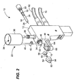
- Fig. 2 is an exploded, perspective view of a microplasma spray apparatus constructed in accordance with the teachings of the disclosure;
- Fig. 3 is a perspective view of the microplasma spray apparatus of Fig. 1, applying a coating to a workpiece; and
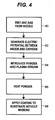
- Fig. 4 is a flowchart describing the process for coating the microplasma spray coating a workpiece without masking.
- While the following disclosure is susceptible to various modifications and alternative constructions, certain illustrative embodiments thereof have been shown in the drawings and will be described below in detail. It should be understood, however, that there is no intention to limit the disclosure to the specific forms disclosed, but on the contrary, the intention is to cover all modifications, alternative constructions, and equivalents falling within the scope of the disclosure as defined by the appended claims.
- Referring now to Fig. 1, a
microplasma spray apparatus 10 schematically represented by the dashed box outline is depicted. In generalized terms, the microplasma spray apparatus includes amicroplasma gun 12 having anarc gas emitter 14, ananode 16, and acathode 18. Anelectric arc 20 is generated between theanode 16 andcathode 18. Aplasma stream 21 is formed when arc gas is injected from thearc gas emitter 14 through thearc 20. A powderedmaterial injector 22 dispenses powdered material into the plasma stream which transports the powdered material to theworkpiece 24. As a result, the powdered material forms a coating with a thickness of approximately 0.0015 to 0.006 inches (0.076 to 0.152 mm) in a desired location on theworkpiece 24. - While a number of different embodiments and structural variations can be constructed to practice such an invention, the following describes one currently known embodiment. Referring now to Fig. 2, an exploded view of such a microplasma spray apparatus is again referred to by
reference numeral 10. As will be described in detail below, themicroplasma spray apparatus 10 is operable for coating many things, including, but not limited to at least a portion of acompressor blade 72 in a gas turbine engine (not shown). However, it is to be understood that the teachings of disclosure can be used to coat myriad other surfaces, including those on aircraft, land-based vehicles, weapons, sea-faring vessels and the like. - In the depicted embodiment, the
microplasma spray apparatus 10 includes theaforementioned microplasma gun 12 having ananode 16 and acathode 18. Thecathode 18 is further depicted to include aninsulated body 26 with anelectrode 28 extending therefrom. Thecathode 18 can also includethreads 30 for threadingly engaging themicroplasma gun 12. Thecathode 18 can also include an O-ring seal 32 to seal the leak path that is created at the interface between thecathode 18 and themicroplasma gun 12. - In operation, an electric arc 20 (Fig. 1) is generated between the
anode 16 andcathode 18 of themicroplasma gun 12. Arc gas such as, but not limited to argon, is emitted into the electric arc formed between theanode 16 and thecathode 18. It should be understood that in practice the arc gas can be emitted prior to generating the electric arc. The electric arc ionizes the gas to create theplasma gas stream 21. The ionization process removes electrons from the arc gas, causing the arc gas to become temporarily unstable. The arc gas heats up to approximately 20,000°F to 30,000°F (11097°C to 16426°C) as it re-stabilizes. The plasma stream cools rapidly after passing through the electric arc. - A powdered
material injector 22 injects powderedmaterial 34 into theplasma gas stream 21. The powderedmaterial 34 is heated and super plasticized in the plasma stream and is deposited on the compressor blade (not shown) where it cools and resolidifies to form the coating. Thepowdered material injector 22 includes apowder hopper 36 for holding thepowdered material 34. Thehopper 36 is attached to themicroplasma gun 12 via a connector 3 8 formed on themicroplasma gun 12. Thepowder hopper 36 holds powdered material to be sprayed onto thecompressor blade 72. Thepowdered material 34 is channeled through adischarge chute 40 and controlled by avalve 42 positioned in thedischarge chute 40. Thevalve 42 can be mechanical or electromechanical as is known to those skilled in the art. Powder may also be injected into the plasma stream via a powder gas line from a standard powder feeder (not shown). - A
nozzle shroud 46 positioned on aforward wall 48 of themicroplasma gun 12 holds anozzle insert 50 and permits theelectrode 28 to extend through acenter aperture 52 formed in thenozzle shroud 46. Thenozzle insert 50 can be threadingly attached to an end of thenozzle shroud 46. Ashield gas cap 54 is positioned adjacent thenozzle shroud 46. Aninsulator 56 is positioned between theshield gas cap 54 and thenozzle shroud 46 to electrically isolate theshield gas cap 54 from thenozzle shroud 46. Theshield gas cap 54 can be pressed to fit onto thenozzle shroud 46 and over theinsulator 56. Theshield gas cap 54 includes a plurality of throughapertures 58 for permitting shield gas to flow therethrough and shield the arc gas from ambient atmosphere. Acenter aperture 60 formed in theshield gas cap 54 permits high velocity arc gas to pass through and into the electric arc. - Cooling fluid, such as water or the like, is utilized to cool the
microplasma gun 12. The cooling fluid is delivered to themicroplasma gun 12 via a coolingfluid hose 62. The cooling fluid traverses through internal passages (not shown) in themicroplasma gun 12 and flows through aninlet passage 64, into ananode holder 66 and back through anoutlet passage 68. The cooling fluid reduces the temperature of theanode 16 during operation of themicroplasma gun 12. The cooling flow rate may be approximately 0.1 to 1.0 gallons per minute. Asecond conduit 70 is connected to themicroplasma gun 12. The second conduit may be operable for providing electrical power, arc gas, and shield gas to themicroplasma gun 12. - Referring now to Fig. 3, it is shown that a localized area of the
compressor blade 72 such as ablade root 74 can be spray coated withpowdered material 34. Theplasma gas stream 21 is directed toward the portion of thecompressor blade 72 to be coated. Themicroplasma gun 12 is operated at a relatively low power range of between approximately 0.5 Kilowatts and 4 Kilowatts. The low power output of themicroplasma gun 12 significantly reduces the heat flow into thecompressor blade 72 over that of conventional coating methods. The maximum surface temperature of thecompressor blade 72 caused by the coating process is approximately 200°F (93°C) depending on the size of the blade. Themicroplasma gun 12 is operable for applyingpowdered material 34 to a thin wall area of thecompressor blade 72 without distorting thecompressor blade 72 because the low power output limits the localized stress caused by high thermal gradients. - The
microplasma gun 12 can apply coating material in narrow strips of about 0.5 mm to about 5 mm in width. This permits accurate surface coating even with a hand held device. The narrow strips of coating substantially eliminate the need for masking or otherwise covering thecompressor blade 72 in areas where the coating is unwanted. The narrow spray pattern is controlled by the nozzle opening size. The hand held version of themicroplasma gun 12 is so accurate that coating can be sprayed on components while they remain installed in an engine or the like. - The arc gas flow rate of the
microplasma apparatus 10 may be between approximately 0.5 and 3 liters per minute. As stated above, the arc gas and shield gas are typically argon, but any suitable inert gas can be utilized as is known to those skilled in the art. The shield gas flow rate ranges between approximately 2 and 8 liters per minute for a typical application. The coating material for thecompressor blade 72 can be a copper-nickel alloy, a copper-aluminum alloy, or other alloys suitable for compressor blades having operating temperatures that are typically below 1000°F (534°C), as is known to those skilled in the art. - The
powder hopper 36 holds thepowdered material 34 prior to being injected into theplasma gas stream 21 by thepowder injector 22. Thepowdered material 34 can be injected into theplasma gas stream 21 either through gravity feed or through a pressurized system (not shown). The shut-offcontrol valve 42 controls thepowdered material 34 feed rate into theplasma gas stream 21.Powdered material 34 is transferred to thecompressor blade 72 from between approximately 1 to 30 grams per minute. Themicroplasma gun 12 can typically apply the coating from distances ranging from approximately 1.5 inches to 8 inches (38 to 203 mm), to thecompressor blade 72, but can vary depending on the coating application requirements. Themicroplasma spray gun 12 can be oriented between a positive 45° angle and a negative 45° angle relative to a normal axis of the compressor blade and still provide adequate material coating with a gravity feed system. A pressure feed system provides unlimited angles or orientation for themicroplasma gun 12. Themicroplasma spray gun 12 generates a relatively low noise level that ranges from between 40 and 70 decibels due to the low power output, thereby making theapparatus 10 suitable for hand held application. Current U.S. government regulations require hearing protection when environmental noise reaches 85 decibels. Themicroplasma spray apparatus 10 can be hand held or alternatively held in an automated fixture (not shown) that is computer controlled. - Referring now to Fig. 4, a block diagram generally describing the operation of the
microplasma spray apparatus 10 and the plasma spray coating process is illustrated. Initially, atblock 80, arc gas is emitted from thenozzle insert 50. An electric potential is generated between theanode 16 and thecathode 18 of theplasma spray gun 12 and is directed through the arc gas, as described inblock 82. Arc gas is directed through the electric potential to create theplasma stream 21. Atblock 84,powdered material 34 is injected into theplasma stream 21. Atblock 86, the plasma stream heats thepowdered material 34 to a "super plasticized" condition such that thepowdered material 34 is malleable when it is applied to a workpiece. Atblock 88, thepowdered material 34 is applied to an unmasked substrate. Thepowdered material 34 then cools and solidifies as a hard coating on the substrate. - While the preceding text sets forth a detailed description of certain embodiments of the invention, it should be understood that the legal scope of the invention is defined by the claims set forth at the end of this patent. The detailed description is to be construed as exemplary only and does not describe every possible embodiment of the invention since describing every possible embodiment would be impractical, if not impossible. Numerous alternative embodiments could be implemented, using either current technology or technology developed after the filing date of this patent, which would still fall within the scope of the claims defining the invention.
Claims (37)
- A microplasma spray apparatus for coating at least a portion of a compressor blade (72) in a gas turbine engine, comprising:a microplasma gun (12) including an anode (16), a cathode (18), and an arc generator for generating an electric arc (20) between the anode (16) and cathode (18);a nozzle for emitting arc gas into the electric arc (20), the electric arc (20) operable for ionizing the gas to create a plasma gas stream (21); anda powder injector (22) for injecting powdered material (34) into the plasma gas stream (21) and coating a localized area of the compressor blade (72), the material coating being applied without masking the compressor blade.
- The microplasma spray apparatus of claim 1, wherein the microplasma gun operates at a relatively low power range between approximately 0.5 Kilowatts and 4 Kilowatts.
- The microplasma spray apparatus of claim 1 or 2, wherein the microplasma gun (12) is operable for applying the material to thin walled portions of the compressor blade (72) without distorting the blade.
- The microplasma spray apparatus of claim 1, wherein a maximum surface temperature of the compressor blade (72) caused by the coating process is approximately 200°F (93°C).
- The microplasma spray apparatus of any preceding claim, wherein the nozzle applies the coating material in narrow widths of about 0.5 to about 5 mm to the compressor blade (72).
- The microplasma spray apparatus of any preceding claim, wherein the arc gas flow rate is between approximately 0.5 and 3 liters per minute.
- The microplasma spray apparatus of any preceding claim, wherein the arc gas is inert.
- The microplasma spray apparatus of claim 7, wherein the arc gas is argon.
- The microplasma spray apparatus of any preceding claim, further including a shield gas cap (54) having shielding gas injected therethrough.
- The microplasma spray apparatus of claim 9, wherein the shielding gas flow rate is between approximately 2 and 8 liters per minute.
- The microplasma spray apparatus of claim 9 or 10, wherein the shielding gas is inert.
- The microplasma spray apparatus of claim 11, wherein the shielding gas is argon.
- The microplasma spray apparatus of any preceding claim, wherein the coating material (34) is a copper and nickel alloy.
- The microplasma spray apparatus of any of claims 1 to 12, wherein the coating material (34) includes an aluminum-copper alloy.
- The microplasma spray apparatus of any preceding claim, further including a powder hopper (36) for holding the powdered material (34) prior to the powdered material (34) being injected into the plasma gas stream.
- The microplasma spray apparatus of any preceding claim, wherein the powder feed rate is approximately between 1 and 30 grams per minute.
- The microplasma spray apparatus of any preceding claim, further including a cooling system for cooling hot portions of the apparatus.
- The microplasma spray apparatus of any preceding claim, wherein the microplasma gun (12) applies the coating from a distance to the compressor blade (72) of between approximately 1.5 inches to 8 inches (38 to 203 mm).
- The microplasma spray apparatus of any preceding claim, wherein the microplasma spray angle relative to a normal axis of the compressor blade (72) is approximately between a positive 45 degree angle and a negative 45 degree angle.
- The microplasma spray apparatus of any preceding claim, wherein the microplasma gun (12) generates a noise level of between approximately 40 and 70 decibels.
- The microplasma spray apparatus of any preceding claim, further including a cathode shroud (46) surrounding a portion of the cathode (18).
- The microplasma spray apparatus of claim 21, further including the arc gas nozzle (50) positioned on the cathode shroud (46) for ejecting arc gas therethrough.
- The microplasma spray apparatus of claim 22, further including a shield gas cap (54) substantially encompassing the cathode shroud (46), the shield gas cap (54) operable for providing shielding gas as a barrier between the arc gas and an ambient atmosphere.
- The microplasma spray apparatus of claim 24, further including a shield cap insulator (56) positioned between the shield gas cap (54) and the cathode shroud (46).
- A method for microplasma spray coating a turbine compressor blade (72), comprising:providing a microplasma gun (12) including an anode (16) and a cathode (18);injecting inert arc gas from a nozzle;generating an electric arc between the anode (16) and the cathode (18) through the arc gas;ionizing the arc gas with the electric arc to form a plasma gas stream (21);injecting powdered material (34) into the plasma gas stream (21); andcoating a localized area (74) of the compressor blade (72) with the powder material without masking the compressor blade.
- A method for repairing a gas turbine compressor blade using a microplasma spray coating apparatus, comprising:using a hand controlled and operated microplasma spray gun (12);injecting inert arc gas through an electric arc generated by the spray gun;ionizing the arc gas with the electric arc to form a plasma gas stream (21);injecting powdered material (34) into the plasma gas stream; andspray coating a localized area (74) of the compressor blade (72) with the powdered material without masking the compressor blade (72) and without utilizing a dedicated spray coating facility.
- The method of claim 25 or 26, further including operating the microplasma gun (12) at a relatively low power range between approximately 0.5 Kilowatts and 4 Kilowatts.
- The method of claim 25, 26 or 27, further including applying the coating material (34) to the compressor blade (72) without causing distortion of the compressor blade.
- The method of any of claims 25 to 28, further including applying the coating material (34) to the compressor blade (72) in narrow widths of about 0.5 mm to about 5 mm.
- The method of any of claims 25 to 29, further including flowing the arc gas at a rate between approximately 0.5 and 3 liters per minute.
- The method of any of claims 25 to 30, further including flowing a shielding gas at a rate between approximately 2 and 8 liters per minute.
- The method of any of claims 25 to 31, further including feeding the powder material (34) at a rate approximately between 1 and 30 grams per minute.
- The method of any of claims 25 to 32, further including cooling the microplasma gun with a water cooling system.
- The method of any of claims 25 to 33, further including applying the coating to the compressor blade from a distance of between approximately 1.5 to 8 inches (38 to 203 mm).
- The method of any of claims 25 to 34, further including applying the coating to the compressor blade (72) with the microplasma gun (12) angle positioned approximately between a positive 45 degree angle and a negative 45 degree angle relative to a normal axis of the part.
- The method of any of claims 25 to 35, further including generating a noise level of between approximately 40 and 70 decibels during operation.
- A microplasma spray apparatus for coating at least a portion of a component, comprising:a microplasma gun (12) including an anode (16), a cathode (18), and an arc generator for generating an electric arc (20) between the anode (16) and cathode (18);a nozzle for emitting arc gas into the electric arc (20), the electric arc (20) operable for ionizing the gas to create a plasma gas stream (21); anda powder injector (22) for injecting powdered material (34) into the plasma gas stream (21) and coating a localized area of the compressor blade (72).
Applications Claiming Priority (3)
| Application Number | Priority Date | Filing Date | Title |
|---|---|---|---|
| US10/976,561 US7763823B2 (en) | 2004-10-29 | 2004-10-29 | Method and apparatus for microplasma spray coating a portion of a compressor blade in a gas turbine engine |
| US11/190,136 US20070023402A1 (en) | 2005-07-26 | 2005-07-26 | Methods for repairing workpieces using microplasma spray coating |
| US11/253,868 US20070087129A1 (en) | 2005-10-19 | 2005-10-19 | Methods for repairing a workpiece |
Publications (3)
| Publication Number | Publication Date |
|---|---|
| EP1652954A1 true EP1652954A1 (en) | 2006-05-03 |
| EP1652954B1 EP1652954B1 (en) | 2009-04-22 |
| EP1652954B9 EP1652954B9 (en) | 2013-08-14 |
Family
ID=35677286
Family Applications (1)
| Application Number | Title | Priority Date | Filing Date |
|---|---|---|---|
| EP05256731.0A Expired - Lifetime EP1652954B9 (en) | 2004-10-29 | 2005-10-31 | Method and apparatus for microplasma spray coating a portion of a compressor blade in a gas turbine engine |
Country Status (3)
| Country | Link |
|---|---|
| EP (1) | EP1652954B9 (en) |
| AT (1) | ATE429523T1 (en) |
| DE (1) | DE602005014066D1 (en) |
Cited By (6)
| Publication number | Priority date | Publication date | Assignee | Title |
|---|---|---|---|---|
| EP1927677A1 (en) * | 2006-11-14 | 2008-06-04 | United Technologies Corporation | Thermal barrier coating for combustor panels |
| CN102395242A (en) * | 2010-06-09 | 2012-03-28 | 通用电气公司 | Power delivery unit, plasma spray system, and method of using plasma spray system |
| CN107570915A (en) * | 2017-09-12 | 2018-01-12 | 重庆科技学院 | Microalloying spot-welding technology fixes solder joint alloy powder coating unit |
| US10144096B2 (en) | 2016-03-22 | 2018-12-04 | General Electric Company | Gas turbine in situ inflatable bladders for on-wing repair |
| CN109128462A (en) * | 2018-07-24 | 2019-01-04 | 叶露穗 | A kind of efficiency plasmatron equipment for stablizing electric arc with magnetic |
| US10190442B2 (en) | 2016-03-22 | 2019-01-29 | General Electric Company | Gas turbine in situ inflatable bladders for on-wing repair |
Citations (6)
| Publication number | Priority date | Publication date | Assignee | Title |
|---|---|---|---|---|
| US4256779A (en) * | 1978-11-03 | 1981-03-17 | United Technologies Corporation | Plasma spray method and apparatus |
| EP0808913A1 (en) * | 1996-05-24 | 1997-11-26 | General Electric Company | Method for repairing a thermal barrier coating |
| US6042880A (en) * | 1998-12-22 | 2000-03-28 | General Electric Company | Renewing a thermal barrier coating system |
| EP1277854A1 (en) * | 2001-07-12 | 2003-01-22 | Snecma Moteurs | Process for the local repairing of pieces coated with a thermal barrier |
| US20030033702A1 (en) * | 2001-08-14 | 2003-02-20 | Berry Thomas Frederic | Restoration of thickness to load-bearing gas turbine engine components |
| US20040084423A1 (en) * | 2002-10-30 | 2004-05-06 | Grossklaus Warren Davis | Method of repairing a stationary shroud of a gas turbine engine using plasma transferred arc welding |
-
2005
- 2005-10-31 EP EP05256731.0A patent/EP1652954B9/en not_active Expired - Lifetime
- 2005-10-31 DE DE602005014066T patent/DE602005014066D1/en not_active Expired - Lifetime
- 2005-10-31 AT AT05256731T patent/ATE429523T1/en not_active IP Right Cessation
Patent Citations (6)
| Publication number | Priority date | Publication date | Assignee | Title |
|---|---|---|---|---|
| US4256779A (en) * | 1978-11-03 | 1981-03-17 | United Technologies Corporation | Plasma spray method and apparatus |
| EP0808913A1 (en) * | 1996-05-24 | 1997-11-26 | General Electric Company | Method for repairing a thermal barrier coating |
| US6042880A (en) * | 1998-12-22 | 2000-03-28 | General Electric Company | Renewing a thermal barrier coating system |
| EP1277854A1 (en) * | 2001-07-12 | 2003-01-22 | Snecma Moteurs | Process for the local repairing of pieces coated with a thermal barrier |
| US20030033702A1 (en) * | 2001-08-14 | 2003-02-20 | Berry Thomas Frederic | Restoration of thickness to load-bearing gas turbine engine components |
| US20040084423A1 (en) * | 2002-10-30 | 2004-05-06 | Grossklaus Warren Davis | Method of repairing a stationary shroud of a gas turbine engine using plasma transferred arc welding |
Cited By (9)
| Publication number | Priority date | Publication date | Assignee | Title |
|---|---|---|---|---|
| EP1927677A1 (en) * | 2006-11-14 | 2008-06-04 | United Technologies Corporation | Thermal barrier coating for combustor panels |
| CN102395242A (en) * | 2010-06-09 | 2012-03-28 | 通用电气公司 | Power delivery unit, plasma spray system, and method of using plasma spray system |
| EP2395819A3 (en) * | 2010-06-09 | 2014-04-23 | General Electric Company | Power delivery unit, plasma spray system, and method of using plasma spray system |
| CN102395242B (en) * | 2010-06-09 | 2015-07-22 | 通用电气公司 | Power delivery unit, plasma spray system, and method of using plasma spray system |
| US10144096B2 (en) | 2016-03-22 | 2018-12-04 | General Electric Company | Gas turbine in situ inflatable bladders for on-wing repair |
| US10190442B2 (en) | 2016-03-22 | 2019-01-29 | General Electric Company | Gas turbine in situ inflatable bladders for on-wing repair |
| CN107570915A (en) * | 2017-09-12 | 2018-01-12 | 重庆科技学院 | Microalloying spot-welding technology fixes solder joint alloy powder coating unit |
| CN107570915B (en) * | 2017-09-12 | 2019-01-22 | 重庆科技学院 | Micro-alloy spot welding process fixed spot alloy powder coating device |
| CN109128462A (en) * | 2018-07-24 | 2019-01-04 | 叶露穗 | A kind of efficiency plasmatron equipment for stablizing electric arc with magnetic |
Also Published As
| Publication number | Publication date |
|---|---|
| DE602005014066D1 (en) | 2009-06-04 |
| ATE429523T1 (en) | 2009-05-15 |
| EP1652954B9 (en) | 2013-08-14 |
| EP1652954B1 (en) | 2009-04-22 |
Similar Documents
| Publication | Publication Date | Title |
|---|---|---|
| US8334473B2 (en) | Method and apparatus for microplasma spray coating a portion of a compressor blade in a gas turbine engine | |
| US8563890B2 (en) | Method and apparatus for microplasma spray coating a portion of a turbine vane in a gas turbine engine | |
| US8507826B2 (en) | Microplasma spray apparatus and method for coating articles using same | |
| US8367967B2 (en) | Method and apparatus for repairing thermal barrier coatings | |
| US20090208662A1 (en) | Methods for Repairing a Workpiece | |
| US7115832B1 (en) | Microplasma spray coating apparatus | |
| EP1743951B1 (en) | Microplasma deposition methods | |
| EP1652953B1 (en) | Methods for repairing a workpiece | |
| EP1652954B1 (en) | Method and apparatus for microplasma spray coating a portion of a compressor blade in a gas turbine engine | |
| EP1652952B1 (en) | Methods for repairing workpieces using microplasma spray coating | |
| EP1652951B1 (en) | Method for microplasma spray coating a portion of a turbine vane in a gas turbine engine | |
| EP1652955B1 (en) | Method for repairing thermal barrier coatings | |
| US20070023402A1 (en) | Methods for repairing workpieces using microplasma spray coating | |
| EP1657322B1 (en) | Plasma spray apparatus | |
| JP2006185905A (en) | Method and device for applying thermal spray of micro-plasma on compressor blade part of gas turbine engine | |
| JP2006187762A (en) | Method and apparatus for repairing thermal barrier coating | |
| JP2006183658A (en) | Method and device for microplasma spray coating a portion of turbine vane in gas turbine engine | |
| EP1749583A1 (en) | Microplasma spray coating apparatus | |
| JP2006131998A (en) | Microplasma spray coating apparatus |
Legal Events
| Date | Code | Title | Description |
|---|---|---|---|
| PUAI | Public reference made under article 153(3) epc to a published international application that has entered the european phase |
Free format text: ORIGINAL CODE: 0009012 |
|
| AK | Designated contracting states |
Kind code of ref document: A1 Designated state(s): AT BE BG CH CY CZ DE DK EE ES FI FR GB GR HU IE IS IT LI LT LU LV MC NL PL PT RO SE SI SK TR |
|
| AX | Request for extension of the european patent |
Extension state: AL BA HR MK YU |
|
| 17P | Request for examination filed |
Effective date: 20060626 |
|
| 17Q | First examination report despatched |
Effective date: 20060801 |
|
| AKX | Designation fees paid |
Designated state(s): AT BE BG CH CY CZ DE DK EE ES FI FR GB GR HU IE IS IT LI LT LU LV MC NL PL PT RO SE SI SK TR |
|
| GRAP | Despatch of communication of intention to grant a patent |
Free format text: ORIGINAL CODE: EPIDOSNIGR1 |
|
| GRAP | Despatch of communication of intention to grant a patent |
Free format text: ORIGINAL CODE: EPIDOSNIGR1 |
|
| GRAS | Grant fee paid |
Free format text: ORIGINAL CODE: EPIDOSNIGR3 |
|
| GRAA | (expected) grant |
Free format text: ORIGINAL CODE: 0009210 |
|
| AK | Designated contracting states |
Kind code of ref document: B1 Designated state(s): AT BE BG CH CY CZ DE DK EE ES FI FR GB GR HU IE IS IT LI LT LU LV MC NL PL PT RO SE SI SK TR |
|
| REG | Reference to a national code |
Ref country code: GB Ref legal event code: FG4D |
|
| REG | Reference to a national code |
Ref country code: CH Ref legal event code: EP |
|
| REG | Reference to a national code |
Ref country code: IE Ref legal event code: FG4D |
|
| REF | Corresponds to: |
Ref document number: 602005014066 Country of ref document: DE Date of ref document: 20090604 Kind code of ref document: P |
|
| NLV1 | Nl: lapsed or annulled due to failure to fulfill the requirements of art. 29p and 29m of the patents act | ||
| PG25 | Lapsed in a contracting state [announced via postgrant information from national office to epo] |
Ref country code: PT Free format text: LAPSE BECAUSE OF FAILURE TO SUBMIT A TRANSLATION OF THE DESCRIPTION OR TO PAY THE FEE WITHIN THE PRESCRIBED TIME-LIMIT Effective date: 20090822 Ref country code: FI Free format text: LAPSE BECAUSE OF FAILURE TO SUBMIT A TRANSLATION OF THE DESCRIPTION OR TO PAY THE FEE WITHIN THE PRESCRIBED TIME-LIMIT Effective date: 20090422 Ref country code: ES Free format text: LAPSE BECAUSE OF FAILURE TO SUBMIT A TRANSLATION OF THE DESCRIPTION OR TO PAY THE FEE WITHIN THE PRESCRIBED TIME-LIMIT Effective date: 20090802 Ref country code: AT Free format text: LAPSE BECAUSE OF FAILURE TO SUBMIT A TRANSLATION OF THE DESCRIPTION OR TO PAY THE FEE WITHIN THE PRESCRIBED TIME-LIMIT Effective date: 20090422 Ref country code: LT Free format text: LAPSE BECAUSE OF FAILURE TO SUBMIT A TRANSLATION OF THE DESCRIPTION OR TO PAY THE FEE WITHIN THE PRESCRIBED TIME-LIMIT Effective date: 20090422 |
|
| PLBI | Opposition filed |
Free format text: ORIGINAL CODE: 0009260 |
|
| PG25 | Lapsed in a contracting state [announced via postgrant information from national office to epo] |
Ref country code: PL Free format text: LAPSE BECAUSE OF FAILURE TO SUBMIT A TRANSLATION OF THE DESCRIPTION OR TO PAY THE FEE WITHIN THE PRESCRIBED TIME-LIMIT Effective date: 20090422 Ref country code: LV Free format text: LAPSE BECAUSE OF FAILURE TO SUBMIT A TRANSLATION OF THE DESCRIPTION OR TO PAY THE FEE WITHIN THE PRESCRIBED TIME-LIMIT Effective date: 20090422 Ref country code: NL Free format text: LAPSE BECAUSE OF FAILURE TO SUBMIT A TRANSLATION OF THE DESCRIPTION OR TO PAY THE FEE WITHIN THE PRESCRIBED TIME-LIMIT Effective date: 20090422 Ref country code: IS Free format text: LAPSE BECAUSE OF FAILURE TO SUBMIT A TRANSLATION OF THE DESCRIPTION OR TO PAY THE FEE WITHIN THE PRESCRIBED TIME-LIMIT Effective date: 20090822 Ref country code: SI Free format text: LAPSE BECAUSE OF FAILURE TO SUBMIT A TRANSLATION OF THE DESCRIPTION OR TO PAY THE FEE WITHIN THE PRESCRIBED TIME-LIMIT Effective date: 20090422 Ref country code: SE Free format text: LAPSE BECAUSE OF FAILURE TO SUBMIT A TRANSLATION OF THE DESCRIPTION OR TO PAY THE FEE WITHIN THE PRESCRIBED TIME-LIMIT Effective date: 20090722 |
|
| 26 | Opposition filed |
Opponent name: SIEMENS AKTIENGESELLSCHAFT Effective date: 20091111 |
|
| PG25 | Lapsed in a contracting state [announced via postgrant information from national office to epo] |
Ref country code: DK Free format text: LAPSE BECAUSE OF FAILURE TO SUBMIT A TRANSLATION OF THE DESCRIPTION OR TO PAY THE FEE WITHIN THE PRESCRIBED TIME-LIMIT Effective date: 20090422 Ref country code: CZ Free format text: LAPSE BECAUSE OF FAILURE TO SUBMIT A TRANSLATION OF THE DESCRIPTION OR TO PAY THE FEE WITHIN THE PRESCRIBED TIME-LIMIT Effective date: 20090422 Ref country code: RO Free format text: LAPSE BECAUSE OF FAILURE TO SUBMIT A TRANSLATION OF THE DESCRIPTION OR TO PAY THE FEE WITHIN THE PRESCRIBED TIME-LIMIT Effective date: 20090422 Ref country code: EE Free format text: LAPSE BECAUSE OF FAILURE TO SUBMIT A TRANSLATION OF THE DESCRIPTION OR TO PAY THE FEE WITHIN THE PRESCRIBED TIME-LIMIT Effective date: 20090422 |
|
| PLAX | Notice of opposition and request to file observation + time limit sent |
Free format text: ORIGINAL CODE: EPIDOSNOBS2 |
|
| PG25 | Lapsed in a contracting state [announced via postgrant information from national office to epo] |
Ref country code: BE Free format text: LAPSE BECAUSE OF FAILURE TO SUBMIT A TRANSLATION OF THE DESCRIPTION OR TO PAY THE FEE WITHIN THE PRESCRIBED TIME-LIMIT Effective date: 20090422 Ref country code: SK Free format text: LAPSE BECAUSE OF FAILURE TO SUBMIT A TRANSLATION OF THE DESCRIPTION OR TO PAY THE FEE WITHIN THE PRESCRIBED TIME-LIMIT Effective date: 20090422 |
|
| PG25 | Lapsed in a contracting state [announced via postgrant information from national office to epo] |
Ref country code: BG Free format text: LAPSE BECAUSE OF FAILURE TO SUBMIT A TRANSLATION OF THE DESCRIPTION OR TO PAY THE FEE WITHIN THE PRESCRIBED TIME-LIMIT Effective date: 20090722 |
|
| PG25 | Lapsed in a contracting state [announced via postgrant information from national office to epo] |
Ref country code: MC Free format text: LAPSE BECAUSE OF NON-PAYMENT OF DUE FEES Effective date: 20091031 |
|
| REG | Reference to a national code |
Ref country code: CH Ref legal event code: PL |
|
| PLAF | Information modified related to communication of a notice of opposition and request to file observations + time limit |
Free format text: ORIGINAL CODE: EPIDOSCOBS2 |
|
| REG | Reference to a national code |
Ref country code: IE Ref legal event code: MM4A |
|
| REG | Reference to a national code |
Ref country code: FR Ref legal event code: ST Effective date: 20100630 |
|
| PG25 | Lapsed in a contracting state [announced via postgrant information from national office to epo] |
Ref country code: FR Free format text: LAPSE BECAUSE OF NON-PAYMENT OF DUE FEES Effective date: 20091102 |
|
| PLBB | Reply of patent proprietor to notice(s) of opposition received |
Free format text: ORIGINAL CODE: EPIDOSNOBS3 |
|
| PG25 | Lapsed in a contracting state [announced via postgrant information from national office to epo] |
Ref country code: IE Free format text: LAPSE BECAUSE OF NON-PAYMENT OF DUE FEES Effective date: 20091031 Ref country code: LI Free format text: LAPSE BECAUSE OF NON-PAYMENT OF DUE FEES Effective date: 20091031 Ref country code: CH Free format text: LAPSE BECAUSE OF NON-PAYMENT OF DUE FEES Effective date: 20091031 Ref country code: GR Free format text: LAPSE BECAUSE OF FAILURE TO SUBMIT A TRANSLATION OF THE DESCRIPTION OR TO PAY THE FEE WITHIN THE PRESCRIBED TIME-LIMIT Effective date: 20090723 |
|
| PG25 | Lapsed in a contracting state [announced via postgrant information from national office to epo] |
Ref country code: IT Free format text: LAPSE BECAUSE OF FAILURE TO SUBMIT A TRANSLATION OF THE DESCRIPTION OR TO PAY THE FEE WITHIN THE PRESCRIBED TIME-LIMIT Effective date: 20090422 |
|
| PG25 | Lapsed in a contracting state [announced via postgrant information from national office to epo] |
Ref country code: LU Free format text: LAPSE BECAUSE OF NON-PAYMENT OF DUE FEES Effective date: 20091031 |
|
| PG25 | Lapsed in a contracting state [announced via postgrant information from national office to epo] |
Ref country code: HU Free format text: LAPSE BECAUSE OF FAILURE TO SUBMIT A TRANSLATION OF THE DESCRIPTION OR TO PAY THE FEE WITHIN THE PRESCRIBED TIME-LIMIT Effective date: 20091023 |
|
| PG25 | Lapsed in a contracting state [announced via postgrant information from national office to epo] |
Ref country code: TR Free format text: LAPSE BECAUSE OF FAILURE TO SUBMIT A TRANSLATION OF THE DESCRIPTION OR TO PAY THE FEE WITHIN THE PRESCRIBED TIME-LIMIT Effective date: 20090422 |
|
| PG25 | Lapsed in a contracting state [announced via postgrant information from national office to epo] |
Ref country code: CY Free format text: LAPSE BECAUSE OF FAILURE TO SUBMIT A TRANSLATION OF THE DESCRIPTION OR TO PAY THE FEE WITHIN THE PRESCRIBED TIME-LIMIT Effective date: 20090422 |
|
| PLCK | Communication despatched that opposition was rejected |
Free format text: ORIGINAL CODE: EPIDOSNREJ1 |
|
| PLBN | Opposition rejected |
Free format text: ORIGINAL CODE: 0009273 |
|
| STAA | Information on the status of an ep patent application or granted ep patent |
Free format text: STATUS: OPPOSITION REJECTED |
|
| 27O | Opposition rejected |
Effective date: 20130630 |
|
| REG | Reference to a national code |
Ref country code: DE Ref legal event code: R100 Ref document number: 602005014066 Country of ref document: DE Effective date: 20130630 |
|
| REG | Reference to a national code |
Ref country code: DE Ref legal event code: R082 Ref document number: 602005014066 Country of ref document: DE Representative=s name: SCHMITT-NILSON SCHRAUD WAIBEL WOHLFROM PATENTA, DE |
|
| REG | Reference to a national code |
Ref country code: DE Ref legal event code: R082 Ref document number: 602005014066 Country of ref document: DE Representative=s name: SCHMITT-NILSON SCHRAUD WAIBEL WOHLFROM PATENTA, DE Ref country code: DE Ref legal event code: R081 Ref document number: 602005014066 Country of ref document: DE Owner name: UNITED TECHNOLOGIES CORP. (N.D.GES.D. STAATES , US Free format text: FORMER OWNER: UNITED TECHNOLOGIES CORPORATION, HARTFORD, CONN., US |
|
| PGFP | Annual fee paid to national office [announced via postgrant information from national office to epo] |
Ref country code: GB Payment date: 20190923 Year of fee payment: 15 |
|
| PGFP | Annual fee paid to national office [announced via postgrant information from national office to epo] |
Ref country code: DE Payment date: 20190918 Year of fee payment: 15 |
|
| REG | Reference to a national code |
Ref country code: DE Ref legal event code: R119 Ref document number: 602005014066 Country of ref document: DE |
|
| GBPC | Gb: european patent ceased through non-payment of renewal fee |
Effective date: 20201031 |
|
| PG25 | Lapsed in a contracting state [announced via postgrant information from national office to epo] |
Ref country code: DE Free format text: LAPSE BECAUSE OF NON-PAYMENT OF DUE FEES Effective date: 20210501 |
|
| PG25 | Lapsed in a contracting state [announced via postgrant information from national office to epo] |
Ref country code: GB Free format text: LAPSE BECAUSE OF NON-PAYMENT OF DUE FEES Effective date: 20201031 |