EP1652783A1 - Pallet holding device - Google Patents
Pallet holding device Download PDFInfo
- Publication number
- EP1652783A1 EP1652783A1 EP04380035A EP04380035A EP1652783A1 EP 1652783 A1 EP1652783 A1 EP 1652783A1 EP 04380035 A EP04380035 A EP 04380035A EP 04380035 A EP04380035 A EP 04380035A EP 1652783 A1 EP1652783 A1 EP 1652783A1
- Authority
- EP
- European Patent Office
- Prior art keywords
- support
- pallet
- base
- plate
- bolt
- Prior art date
- Legal status (The legal status is an assumption and is not a legal conclusion. Google has not performed a legal analysis and makes no representation as to the accuracy of the status listed.)
- Withdrawn
Links
- 238000000926 separation method Methods 0.000 claims abstract description 5
- 230000008878 coupling Effects 0.000 claims abstract description 4
- 238000010168 coupling process Methods 0.000 claims abstract description 4
- 238000005859 coupling reaction Methods 0.000 claims abstract description 4
- 238000005192 partition Methods 0.000 claims description 3
- 239000011796 hollow space material Substances 0.000 claims 1
- 230000014759 maintenance of location Effects 0.000 claims 1
- 239000000463 material Substances 0.000 description 6
- 238000004519 manufacturing process Methods 0.000 description 5
- 239000004033 plastic Substances 0.000 description 5
- 238000013461 design Methods 0.000 description 3
- 230000015572 biosynthetic process Effects 0.000 description 2
- 238000011161 development Methods 0.000 description 2
- 238000012986 modification Methods 0.000 description 2
- 230000004048 modification Effects 0.000 description 2
- 238000000465 moulding Methods 0.000 description 2
- 230000002787 reinforcement Effects 0.000 description 2
- 239000002023 wood Substances 0.000 description 2
- 230000006978 adaptation Effects 0.000 description 1
- 230000004075 alteration Effects 0.000 description 1
- 238000013459 approach Methods 0.000 description 1
- 238000012423 maintenance Methods 0.000 description 1
- 238000005259 measurement Methods 0.000 description 1
- 239000002991 molded plastic Substances 0.000 description 1
- 230000000284 resting effect Effects 0.000 description 1
Images
Classifications
-
- B—PERFORMING OPERATIONS; TRANSPORTING
- B65—CONVEYING; PACKING; STORING; HANDLING THIN OR FILAMENTARY MATERIAL
- B65D—CONTAINERS FOR STORAGE OR TRANSPORT OF ARTICLES OR MATERIALS, e.g. BAGS, BARRELS, BOTTLES, BOXES, CANS, CARTONS, CRATES, DRUMS, JARS, TANKS, HOPPERS, FORWARDING CONTAINERS; ACCESSORIES, CLOSURES, OR FITTINGS THEREFOR; PACKAGING ELEMENTS; PACKAGES
- B65D19/00—Pallets or like platforms, with or without side walls, for supporting loads to be lifted or lowered
- B65D19/38—Details or accessories
- B65D19/40—Elements for spacing platforms from supporting surface
-
- F—MECHANICAL ENGINEERING; LIGHTING; HEATING; WEAPONS; BLASTING
- F24—HEATING; RANGES; VENTILATING
- F24C—DOMESTIC STOVES OR RANGES ; DETAILS OF DOMESTIC STOVES OR RANGES, OF GENERAL APPLICATION
- F24C15/00—Details
- F24C15/02—Doors specially adapted for stoves or ranges
- F24C15/024—Handles
-
- B—PERFORMING OPERATIONS; TRANSPORTING
- B65—CONVEYING; PACKING; STORING; HANDLING THIN OR FILAMENTARY MATERIAL
- B65D—CONTAINERS FOR STORAGE OR TRANSPORT OF ARTICLES OR MATERIALS, e.g. BAGS, BARRELS, BOTTLES, BOXES, CANS, CARTONS, CRATES, DRUMS, JARS, TANKS, HOPPERS, FORWARDING CONTAINERS; ACCESSORIES, CLOSURES, OR FITTINGS THEREFOR; PACKAGING ELEMENTS; PACKAGES
- B65D19/00—Pallets or like platforms, with or without side walls, for supporting loads to be lifted or lowered
- B65D19/0004—Rigid pallets without side walls
- B65D19/0006—Rigid pallets without side walls the load supporting surface being made of a single element
- B65D19/0008—Rigid pallets without side walls the load supporting surface being made of a single element forming a continuous plane contact surface
- B65D19/001—Rigid pallets without side walls the load supporting surface being made of a single element forming a continuous plane contact surface the base surface being made of a single element
- B65D19/0014—Rigid pallets without side walls the load supporting surface being made of a single element forming a continuous plane contact surface the base surface being made of a single element forming discontinuous or non-planar contact surfaces
- B65D19/0018—Rigid pallets without side walls the load supporting surface being made of a single element forming a continuous plane contact surface the base surface being made of a single element forming discontinuous or non-planar contact surfaces and each contact surface having a discrete foot-like shape
-
- F—MECHANICAL ENGINEERING; LIGHTING; HEATING; WEAPONS; BLASTING
- F24—HEATING; RANGES; VENTILATING
- F24C—DOMESTIC STOVES OR RANGES ; DETAILS OF DOMESTIC STOVES OR RANGES, OF GENERAL APPLICATION
- F24C15/00—Details
- F24C15/02—Doors specially adapted for stoves or ranges
- F24C15/04—Doors specially adapted for stoves or ranges with transparent panels
-
- B—PERFORMING OPERATIONS; TRANSPORTING
- B65—CONVEYING; PACKING; STORING; HANDLING THIN OR FILAMENTARY MATERIAL
- B65D—CONTAINERS FOR STORAGE OR TRANSPORT OF ARTICLES OR MATERIALS, e.g. BAGS, BARRELS, BOTTLES, BOXES, CANS, CARTONS, CRATES, DRUMS, JARS, TANKS, HOPPERS, FORWARDING CONTAINERS; ACCESSORIES, CLOSURES, OR FITTINGS THEREFOR; PACKAGING ELEMENTS; PACKAGES
- B65D2519/00—Pallets or like platforms, with or without side walls, for supporting loads to be lifted or lowered
- B65D2519/00004—Details relating to pallets
- B65D2519/00258—Overall construction
- B65D2519/00263—Overall construction of the pallet
- B65D2519/00273—Overall construction of the pallet made of more than one piece
-
- B—PERFORMING OPERATIONS; TRANSPORTING
- B65—CONVEYING; PACKING; STORING; HANDLING THIN OR FILAMENTARY MATERIAL
- B65D—CONTAINERS FOR STORAGE OR TRANSPORT OF ARTICLES OR MATERIALS, e.g. BAGS, BARRELS, BOTTLES, BOXES, CANS, CARTONS, CRATES, DRUMS, JARS, TANKS, HOPPERS, FORWARDING CONTAINERS; ACCESSORIES, CLOSURES, OR FITTINGS THEREFOR; PACKAGING ELEMENTS; PACKAGES
- B65D2519/00—Pallets or like platforms, with or without side walls, for supporting loads to be lifted or lowered
- B65D2519/00004—Details relating to pallets
- B65D2519/00258—Overall construction
- B65D2519/00283—Overall construction of the load supporting surface
- B65D2519/00288—Overall construction of the load supporting surface made of one piece
-
- B—PERFORMING OPERATIONS; TRANSPORTING
- B65—CONVEYING; PACKING; STORING; HANDLING THIN OR FILAMENTARY MATERIAL
- B65D—CONTAINERS FOR STORAGE OR TRANSPORT OF ARTICLES OR MATERIALS, e.g. BAGS, BARRELS, BOTTLES, BOXES, CANS, CARTONS, CRATES, DRUMS, JARS, TANKS, HOPPERS, FORWARDING CONTAINERS; ACCESSORIES, CLOSURES, OR FITTINGS THEREFOR; PACKAGING ELEMENTS; PACKAGES
- B65D2519/00—Pallets or like platforms, with or without side walls, for supporting loads to be lifted or lowered
- B65D2519/00004—Details relating to pallets
- B65D2519/00258—Overall construction
- B65D2519/00313—Overall construction of the base surface
- B65D2519/00323—Overall construction of the base surface made of more than one piece
-
- B—PERFORMING OPERATIONS; TRANSPORTING
- B65—CONVEYING; PACKING; STORING; HANDLING THIN OR FILAMENTARY MATERIAL
- B65D—CONTAINERS FOR STORAGE OR TRANSPORT OF ARTICLES OR MATERIALS, e.g. BAGS, BARRELS, BOTTLES, BOXES, CANS, CARTONS, CRATES, DRUMS, JARS, TANKS, HOPPERS, FORWARDING CONTAINERS; ACCESSORIES, CLOSURES, OR FITTINGS THEREFOR; PACKAGING ELEMENTS; PACKAGES
- B65D2519/00—Pallets or like platforms, with or without side walls, for supporting loads to be lifted or lowered
- B65D2519/00004—Details relating to pallets
- B65D2519/00258—Overall construction
- B65D2519/00313—Overall construction of the base surface
- B65D2519/00328—Overall construction of the base surface shape of the contact surface of the base
- B65D2519/00338—Overall construction of the base surface shape of the contact surface of the base contact surface having a discrete foot-like shape
-
- B—PERFORMING OPERATIONS; TRANSPORTING
- B65—CONVEYING; PACKING; STORING; HANDLING THIN OR FILAMENTARY MATERIAL
- B65D—CONTAINERS FOR STORAGE OR TRANSPORT OF ARTICLES OR MATERIALS, e.g. BAGS, BARRELS, BOTTLES, BOXES, CANS, CARTONS, CRATES, DRUMS, JARS, TANKS, HOPPERS, FORWARDING CONTAINERS; ACCESSORIES, CLOSURES, OR FITTINGS THEREFOR; PACKAGING ELEMENTS; PACKAGES
- B65D2519/00—Pallets or like platforms, with or without side walls, for supporting loads to be lifted or lowered
- B65D2519/00004—Details relating to pallets
- B65D2519/00547—Connections
- B65D2519/00552—Structures connecting the constitutive elements of the pallet to each other, i.e. load supporting surface, base surface and/or separate spacer
- B65D2519/00572—Structures connecting the constitutive elements of the pallet to each other, i.e. load supporting surface, base surface and/or separate spacer with separate auxiliary element, e.g. screws, nails, bayonets
Definitions
- the present invention refers to a pallet holding device, which provides essential novelty features and significant advantages with respect to the means known and used for the same purposes in the current state of the art.
- the invention proposes the development of a device which, being of an extremely simple conception, allows its adaptation to a flat support plate, whether wooden, of corrugated cardboard or of any other material, by means of a simple, practical and quick threading or clipping operation.
- the device comprises two separate elements, preferably manufactured with a plastic susceptible to jet molding, designed to allow their mutual coupling, one element of which has been configured in the form of a stopper provided with a bolt or threaded screw (or, where applicable, in the form of a clip), and the other element has been configured in the form of a body serving as a base, and has been configured in a cylindrical shape, with an axial internal hole extended to a predetermined length (or, where applicable, with a clipping configuration, as convenient), and with the formation of internal ribs on the rest of the height of the hollow interior of this element, also having at least one lateral incision for guiding the strap which potentially may be used for holding goods on the support base.
- the field of application of the invention is comprised within the sector for the manufacture of jet moulded plastic parts, and especially, of parts for use in pallet manufacturing.
- pallets With a view to holding goods of a very different class has been generally known by all for many years. Regardless of any consideration relative to measurements and design, the usual pallets are normally manufactured with wood, although more recently other materials, such as plastic or even corrugated cardboard, are also used.
- the present invention has set out to provide, as a main objective, a solution which proves truly efficient for an .advantageous simplification of the manufacture and handling of this type of supports.
- the invention has carried out the development of a pallet holding device, conceived for being applied to a flat support plate constituting the pallet surface itself, and which can consist of a plastic, wooden or corrugated cardboard plate, or of any other material, such that the recommended device can be applied to said support plate in different predetermined locations, thereby constituting means of support and separation of the support plate with respect to the ground or other support surface.
- the device of the invention consists of two independent, separate elements or parts, preferably manufactured by means of jet moulding with a plastic material prepared for giving said parts the desired features of structural resistance, durability and handling.
- these parts one of them has been configured in the form of a stopper, and has a preferably circular head of considerable diameter, from which a bolt orthogonally projects which can be threaded or configured in the form of a clip, as convenient;
- the other part consists of a base and support element which has been generally developed advantageously in a cylindrical shape (without the chosen configuration implying any limitation, since the outer shape of the base element has no influence whatsoever on the behaviour and the use of the assembly), the height of which determines the separation between the flat support plate and the ground or other support surface, the body of the base part having an axial hole extending to a portion of the height of the cylinder, and the part being internally hollow throughout the rest of the height, with the formation of reinforcement partitions at diametrically opposite positions (for example, four partitions
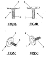
- This stopper element has a head (2) which is generally of a circular design, of sufficient thickness, from one of the flat sides of which a bolt or threaded rod 3, in the manner of a screw and of a predetermined length, orthogonally projects.
- the diameter of the circular head 2 will be of sufficient dimensions so as to allow a convenient handling (manual or of another type) during the pallet assembly operation.
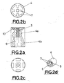
- FIGS. 2a to 2d show the second part comprised by the assembly of the invention.
- Said second part is preferably, as stated, of a generally cylindrical shape, and constitutes the element for support or resting the pallet on the support surface (the ground or any other).
- This support part has been generally indicated in the drawings with reference number 4, and is divided, in height, into two portions 4a and 4b, of which a first portion 4a, which in operative position of the part (assembled pallet) will occupy an upper position, has an axial hole 5 internally threaded in correspondence with the thread of the bolt 3 of the first part or stopper 1, whereas the second portion 4b of this part, which in operative position will occupy a lower position, has an internal hollow part for lightening the part, towards which walls or longitudinal ribs 7 project, which are angularly equidistant for the internal reinforcement of the latter, and which in the chosen embodiment four walls 7 successively separated between each other by 90° angles, have been chosen, however this detail should not be interpreted as limiting
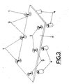
- FIG. 3 a graphic representation of a pallet susceptible to be assembled with the device of the invention along with a flat plate of an appropriate material such as wood, plastic, corrugated cardboard, or similar, has been depicted in Figure 3.
- the flat plate is identified in the drawing with reference number 8, being of a generally rectangular design and of dimensions adapted to the standard dimensions for this type of support elements.
- the carrying out of through holes 9 of appropriate diameters has been foreseen, preferably countersunk holes so as to adapt to the shape of each one of the stopper elements 1 and to level with the circular head 2 of the latter when each one of said stopper elements is made to pass through a corresponding hole 9 from one of the sides of the plate 8, for its fixing to a respective cylindrical part 4 located on the other side of said plate 8.
- the mentioned plate 8 of the pallet thus constructed provides, when it is in operative position, the support base for holding goods on its upper side, whereas it remains separate from the support plane (the ground or any other) at a distance equivalent to the height of the support parts 4.
- the height of said support parts 4 will be chosen such that it is enough for a convenient and efficient handling of the assembly, whether with fork lift trucks or with any other traditional means.
- each stopper element 1 has a threaded rod 3 in the manner of a screw
- the support part 4 shows a portion provided with an axial hole 5, likewise threaded so as to receive and mesh with the mentioned rod 3.
- This embodiment despite being the, preferred one for the device of the invention, can be modified and replaced by a constructive form in which the threaded rod 3 and the hole 5 constitute quick attachment clipping elements. With this, as an additional advantage, a smaller pallet assembly time will be obtained when it is to be used for any transport or storage function. In any case, both configurations allow their disassembly if necessary.
- the support part 4 also has a further use constituting an important detail with a view to the fixing of the goods on the support plate 8 of the pallet.
- Said use consists in the provision of an incision or cut 10 affecting one portion of the side surface of the cylindrical body constituting each one of these parts, and which extends parallelly to the upper perimetral edge (according to the operative position) of the body of the part 4, near said upper edge, i.e. near the end of the body 4 intended for occupying an adjacent position to the corresponding side of said pallet plate 8, as can be seen with greater detail in Figure 2a of the drawings.
- This grooving is wide enough to allow the housing of a marginal portion of the strapping elements usually used to hold the goods down onto the pallet plate 8, thereby ensuring the maintenance of said strapping elements in operative position, and therefore a more secure handling of loaded pallets.
Landscapes
- Engineering & Computer Science (AREA)
- Mechanical Engineering (AREA)
- Chemical & Material Sciences (AREA)
- Combustion & Propulsion (AREA)
- General Engineering & Computer Science (AREA)
- Pallets (AREA)
- Electric Ovens (AREA)
Abstract


Description
- The present invention refers to a pallet holding device, which provides essential novelty features and significant advantages with respect to the means known and used for the same purposes in the current state of the art.
- More specifically, the invention proposes the development of a device which, being of an extremely simple conception, allows its adaptation to a flat support plate, whether wooden, of corrugated cardboard or of any other material, by means of a simple, practical and quick threading or clipping operation. To this end, the device comprises two separate elements, preferably manufactured with a plastic susceptible to jet molding, designed to allow their mutual coupling, one element of which has been configured in the form of a stopper provided with a bolt or threaded screw (or, where applicable, in the form of a clip), and the other element has been configured in the form of a body serving as a base, and has been configured in a cylindrical shape, with an axial internal hole extended to a predetermined length (or, where applicable, with a clipping configuration, as convenient), and with the formation of internal ribs on the rest of the height of the hollow interior of this element, also having at least one lateral incision for guiding the strap which potentially may be used for holding goods on the support base.
- The field of application of the invention is comprised within the sector for the manufacture of jet moulded plastic parts, and especially, of parts for use in pallet manufacturing.
- The growing use made of pallets with a view to holding goods of a very different class has been generally known by all for many years. Regardless of any consideration relative to measurements and design, the usual pallets are normally manufactured with wood, although more recently other materials, such as plastic or even corrugated cardboard, are also used.
- In any case, the manufacture of the current pallets is usually laborious and therefore expensive, and furthermore, they occupy a space which comes to be quite considerable in those locations where this type of supporting elements is more greatly used.
- Taking the previous approach into consideration, the present invention has set out to provide, as a main objective, a solution which proves truly efficient for an .advantageous simplification of the manufacture and handling of this type of supports. Basically, the invention has carried out the development of a pallet holding device, conceived for being applied to a flat support plate constituting the pallet surface itself, and which can consist of a plastic, wooden or corrugated cardboard plate, or of any other material, such that the recommended device can be applied to said support plate in different predetermined locations, thereby constituting means of support and separation of the support plate with respect to the ground or other support surface. As has been summarily indicated in the foregoing, the device of the invention consists of two independent, separate elements or parts, preferably manufactured by means of jet moulding with a plastic material prepared for giving said parts the desired features of structural resistance, durability and handling. Of these parts, one of them has been configured in the form of a stopper, and has a preferably circular head of considerable diameter, from which a bolt orthogonally projects which can be threaded or configured in the form of a clip, as convenient; the other part consists of a base and support element which has been generally developed advantageously in a cylindrical shape (without the chosen configuration implying any limitation, since the outer shape of the base element has no influence whatsoever on the behaviour and the use of the assembly), the height of which determines the separation between the flat support plate and the ground or other support surface, the body of the base part having an axial hole extending to a portion of the height of the cylinder, and the part being internally hollow throughout the rest of the height, with the formation of reinforcement partitions at diametrically opposite positions (for example, four partitions angularly separated by 90°). The axial hole of this part can be internally threaded or can be configured in the form of a clip, as it complementarily corresponds with the embodiment chosen for the bolt of the stopper part.
- These and other features and advantages of the invention will be more shown more clearly in the following detailed description following a preferred embodiment, given only as an illustrative and non-limiting example, with reference to the attached drawings, in which:
- Figures 1a to 1d show side elevation, cross-sectional and perspective views of both sides, respectively, of a stopper part constructed according to the invention;
- Figures 2a to 2d show side elevation (with a partial section), bottom plan, top plan and perspective views, respectively, of the base part provided for by the assembly of the invention, and
- Figure 3 is a schematic illustration, in perspective view, of a pallet constructed with the help of the device of the invention.
- As indicated in the foregoing, the detailed description of the preferred embodiment of the invention will be carried out with the help of the attached drawings, throughout which the same reference numbers are used to identify same or similar parts. In this sense, with reference firstly to the representations appearing in Figures 1a to 1d, the general configuration which has been foreseen for the preferred embodiment of the stopper element implicated in the assembly of the device of the invention can be seen. This stopper element, generally indicated with reference number 1, has a head (2) which is generally of a circular design, of sufficient thickness, from one of the flat sides of which a bolt or threaded
rod 3, in the manner of a screw and of a predetermined length, orthogonally projects. For its part, the diameter of thecircular head 2 will be of sufficient dimensions so as to allow a convenient handling (manual or of another type) during the pallet assembly operation. - Figures 2a to 2d show the second part comprised by the assembly of the invention. Said second part is preferably, as stated, of a generally cylindrical shape, and constitutes the element for support or resting the pallet on the support surface (the ground or any other). This support part has been generally indicated in the drawings with
reference number 4, and is divided, in height, into twoportions first portion 4a, which in operative position of the part (assembled pallet) will occupy an upper position, has anaxial hole 5 internally threaded in correspondence with the thread of thebolt 3 of the first part or stopper 1, whereas thesecond portion 4b of this part, which in operative position will occupy a lower position, has an internal hollow part for lightening the part, towards which walls orlongitudinal ribs 7 project, which are angularly equidistant for the internal reinforcement of the latter, and which in the chosen embodiment fourwalls 7 successively separated between each other by 90° angles, have been chosen, however this detail should not be interpreted as limiting, given that the number of these ribs can be variable, as the separation between them is likewise variable. - Finally, a graphic representation of a pallet susceptible to be assembled with the device of the invention along with a flat plate of an appropriate material such as wood, plastic, corrugated cardboard, or similar, has been depicted in Figure 3. The flat plate is identified in the drawing with
reference number 8, being of a generally rectangular design and of dimensions adapted to the standard dimensions for this type of support elements. In predetermined positions preferably distributed along the major sides of theflat plate 8, the carrying out of throughholes 9 of appropriate diameters has been foreseen, preferably countersunk holes so as to adapt to the shape of each one of the stopper elements 1 and to level with thecircular head 2 of the latter when each one of said stopper elements is made to pass through acorresponding hole 9 from one of the sides of theplate 8, for its fixing to a respectivecylindrical part 4 located on the other side ofsaid plate 8. In this way, the mentionedplate 8 of the pallet thus constructed provides, when it is in operative position, the support base for holding goods on its upper side, whereas it remains separate from the support plane (the ground or any other) at a distance equivalent to the height of thesupport parts 4. - As will be understood, the height of said
support parts 4 will be chosen such that it is enough for a convenient and efficient handling of the assembly, whether with fork lift trucks or with any other traditional means. - On the other hand, the representation of the Figures shows an embodiment wherein each stopper element 1 has a threaded
rod 3 in the manner of a screw, and thesupport part 4 shows a portion provided with anaxial hole 5, likewise threaded so as to receive and mesh with the mentionedrod 3. This embodiment, despite being the, preferred one for the device of the invention, can be modified and replaced by a constructive form in which the threadedrod 3 and thehole 5 constitute quick attachment clipping elements. With this, as an additional advantage, a smaller pallet assembly time will be obtained when it is to be used for any transport or storage function. In any case, both configurations allow their disassembly if necessary. - The
support part 4 also has a further use constituting an important detail with a view to the fixing of the goods on thesupport plate 8 of the pallet. Said use consists in the provision of an incision or cut 10 affecting one portion of the side surface of the cylindrical body constituting each one of these parts, and which extends parallelly to the upper perimetral edge (according to the operative position) of the body of thepart 4, near said upper edge, i.e. near the end of thebody 4 intended for occupying an adjacent position to the corresponding side of saidpallet plate 8, as can be seen with greater detail in Figure 2a of the drawings. This grooving is wide enough to allow the housing of a marginal portion of the strapping elements usually used to hold the goods down onto thepallet plate 8, thereby ensuring the maintenance of said strapping elements in operative position, and therefore a more secure handling of loaded pallets. - It is not considered necessary to further extend the content of this description in order for a person skilled in the art may understand its scope and the advantages derived from the invention, as well as to develop and to put into practice the object thereof.
- Nevertheless, it must be understood that the invention has been described according to a preferred embodiment thereof, thus it can be subject to modifications without this implying any alteration of the basis of said invention, said modifications being able to affect, especially, the shape, size and/or manufacturing materials of the assembly or of its parts.
Claims (2)
- A pallet holding device, for its coupling, in a predetermined number, in previously established positions on the support bases or plates for holding goods constituting the pallet, for the support and separation of said support bases with respect to the receiving or support surface of the assembly, characterised in that it is composed of two parts (1, 4) susceptible to mutual coupling and retention by means of threading or clipping, of which a first part (1) consists of a stopper element formed by a circular head (2) of predetermined diameter from which a bolt or rod (3) orthogonally projects, threaded or clip-configured, susceptible to passing through the mentioned support base or plate (8) for holding the goods from a first side thereof through the holes (9) carried out to this end, and a second part (4) intended for being located on the opposite side of said base or plate (8) and to serve as a support element, is constituted in the form of a preferably cylindrical body, provided with an axial hole (5) internally threaded or clip-configured complementarily with the bolt (3) of the first part which it receives and houses, this hole (5) extending to a predetermined length of the height of said second part, whereas the rest of the body of the part has an internal hollow space (6) with longitudinal partitions (7) ribbed in diametrically opposite positions.
- A device according to claim 1, characterised in that said second part (4) has a lateral incision (10) near the end adjacent to the support base or plate to which it is attached, intended for receiving a strapping element or the like.
Applications Claiming Priority (1)
| Application Number | Priority Date | Filing Date | Title |
|---|---|---|---|
| ES200302175A ES2200718B2 (en) | 2003-09-11 | 2003-09-11 | DOOR FOR OVEN. |
Publications (1)
| Publication Number | Publication Date |
|---|---|
| EP1652783A1 true EP1652783A1 (en) | 2006-05-03 |
Family
ID=31970661
Family Applications (1)
| Application Number | Title | Priority Date | Filing Date |
|---|---|---|---|
| EP04380035A Withdrawn EP1652783A1 (en) | 2003-09-11 | 2004-02-13 | Pallet holding device |
Country Status (2)
| Country | Link |
|---|---|
| EP (1) | EP1652783A1 (en) |
| ES (1) | ES2200718B2 (en) |
Cited By (1)
| Publication number | Priority date | Publication date | Assignee | Title |
|---|---|---|---|---|
| CN106885527A (en) * | 2017-02-14 | 2017-06-23 | 中冶建筑研究总院有限公司 | A kind of monitoring device on timber structure |
Citations (4)
| Publication number | Priority date | Publication date | Assignee | Title |
|---|---|---|---|---|
| US3610172A (en) * | 1969-08-21 | 1971-10-05 | Menasha Corp | Pallet construction |
| GB1349493A (en) * | 1973-02-22 | 1974-04-03 | Wiggins Teape Research Dev Ltd | Packaging |
| US4128253A (en) * | 1977-10-14 | 1978-12-05 | Powers Richard J | Pallet and roller post construction therefor |
| EP0153917A2 (en) * | 1984-02-10 | 1985-09-04 | Jean Van Nes | Pallet assembly |
Family Cites Families (5)
| Publication number | Priority date | Publication date | Assignee | Title |
|---|---|---|---|---|
| US3818890A (en) * | 1973-07-16 | 1974-06-25 | Gen Motors Corp | Ventilated windowed oven door |
| US5562090A (en) * | 1993-07-22 | 1996-10-08 | General Electric Company | Oven door having a cooling arrangement |
| GB2290611B (en) * | 1994-06-14 | 1998-06-24 | Blue Circle Domestic Appliance | Cooking appliances |
| DE59702655D1 (en) * | 1996-06-05 | 2000-12-28 | Aeg Hausgeraete Gmbh | Door to close the muffle of a baking and roasting oven |
| DE19853758C2 (en) * | 1998-11-21 | 2001-10-18 | Ege Elektro Gmbh | Oven door with window and operating handle |
-
2003
- 2003-09-11 ES ES200302175A patent/ES2200718B2/en not_active Expired - Fee Related
-
2004
- 2004-02-13 EP EP04380035A patent/EP1652783A1/en not_active Withdrawn
Patent Citations (4)
| Publication number | Priority date | Publication date | Assignee | Title |
|---|---|---|---|---|
| US3610172A (en) * | 1969-08-21 | 1971-10-05 | Menasha Corp | Pallet construction |
| GB1349493A (en) * | 1973-02-22 | 1974-04-03 | Wiggins Teape Research Dev Ltd | Packaging |
| US4128253A (en) * | 1977-10-14 | 1978-12-05 | Powers Richard J | Pallet and roller post construction therefor |
| EP0153917A2 (en) * | 1984-02-10 | 1985-09-04 | Jean Van Nes | Pallet assembly |
Cited By (1)
| Publication number | Priority date | Publication date | Assignee | Title |
|---|---|---|---|---|
| CN106885527A (en) * | 2017-02-14 | 2017-06-23 | 中冶建筑研究总院有限公司 | A kind of monitoring device on timber structure |
Also Published As
| Publication number | Publication date |
|---|---|
| ES2200718B2 (en) | 2004-12-16 |
| ES2200718A1 (en) | 2004-03-01 |
Similar Documents
| Publication | Publication Date | Title |
|---|---|---|
| US3438342A (en) | Material-handling pallet and improved pallet leg or support and load-distributing attachment therefor | |
| US2930560A (en) | Material handling pallet | |
| US3750596A (en) | Interlocking storage pallet | |
| US4606278A (en) | Twin sheet pallet | |
| US6622642B2 (en) | Thermoplastic pallet | |
| US7735429B2 (en) | Connector for support structures | |
| US5492069A (en) | Pallet assembly | |
| EP4345023B1 (en) | Assembled plastic pallet | |
| US20180229887A1 (en) | Nestable pallet with runners | |
| CN203889225U (en) | Recyclable and renewable environmentally friendly pallet structure | |
| WO2007136480A2 (en) | A molded pallet having integral and structurally improved tie down points | |
| EP1045796B1 (en) | Prefabricated pallet | |
| US20190071234A1 (en) | Collapsible container | |
| FI68583C (en) | Cargo pallet | |
| EP1652783A1 (en) | Pallet holding device | |
| US5862760A (en) | Pallet assembly | |
| ES2293329T3 (en) | PLASTIC TRANSPORT PALE. | |
| CA2358881C (en) | Shipping pod | |
| JPH0672443A (en) | Storage-transport deice for cylindrical object | |
| JP4572899B2 (en) | Plastic pallet | |
| EP1970317B1 (en) | Pallet for beer barrels and the like | |
| EP2108593B1 (en) | Container for storage and transport | |
| ES2557815B1 (en) | PALLET WITH UPPER INTERLOCK SURFACE | |
| KR101713623B1 (en) | veneer board using pallet | |
| US3106174A (en) | Expendable pallet |
Legal Events
| Date | Code | Title | Description |
|---|---|---|---|
| APBN | Date of receipt of notice of appeal recorded |
Free format text: ORIGINAL CODE: EPIDOSNNOA2E |
|
| APBR | Date of receipt of statement of grounds of appeal recorded |
Free format text: ORIGINAL CODE: EPIDOSNNOA3E |
|
| APBV | Interlocutory revision of appeal recorded |
Free format text: ORIGINAL CODE: EPIDOSNIRAPE |
|
| PUAI | Public reference made under article 153(3) epc to a published international application that has entered the european phase |
Free format text: ORIGINAL CODE: 0009012 |
|
| AK | Designated contracting states |
Kind code of ref document: A1 Designated state(s): AT BE BG CH CY CZ DE DK EE ES FI FR GB GR HU IE IT LI LU MC NL PT RO SE SI SK TR |
|
| AX | Request for extension of the european patent |
Extension state: AL LT LV MK |
|
| 17P | Request for examination filed |
Effective date: 20061103 |
|
| AKX | Designation fees paid |
Designated state(s): AT BE BG CH CY CZ DE DK EE ES FI FR GB GR HU IE IT LI LU MC NL PT RO SE SI SK TR |
|
| STAA | Information on the status of an ep patent application or granted ep patent |
Free format text: STATUS: THE APPLICATION IS DEEMED TO BE WITHDRAWN |
|
| 18D | Application deemed to be withdrawn |
Effective date: 20060901 |